

Great Planes GPMA1112 User Manual

WARRANTY
Great Planes
®
Model Manufacturing Co. guarantees this kit to be free from defects in both material and workmanship at the date of
purchase. This warranty does not cover any component parts damaged by use or modification. In no case shall Great Planes’ liability
exceed the original cost of the purchased kit. Further, Great Planes reserves the right to change or modify this warranty without notice.
In that Great Planes has no control over the final assembly or material used for final assembly, no liability shall be assumed nor
accepted for any damage resulting from the use by the user of the final user-assembled product. By the act of using the user-assembled
product, the user accepts all resulting liability.
If the buyer is not prepared to accept the liability associated with the use of this product, the buyer is advised to return this
kit immediately in new and unused condition to the place of purchase.
To make a warranty claim send the defective part or item to Hobby Services at the address below:
Hobby Services
3002 N. Apollo Dr. Suite 1
Champaign IL 61822 USA
Include a letter stating your name, return shipping address, as much contact information as possible (daytime telephone number, fax
number, e-mail address), a detailed description of the problem and a photocopy of the purchase receipt. Upon receipt of the package
the problem will be evaluated as quickly as possible.
READ THROUGH THIS MANUAL BEFORE STARTING
CONSTRUCTION. IT CONTAINS IMPORTANT WARNINGS
AND INSTRUCTIONS CONCERNING THE ASSEMBLY
AND USE OF THIS MODEL.
GPMZ0171 for GPMA1112 V1.0© Copyright 2005
Champaign, Illinois
(217) 398-8970, Ext 5
airsupport@greatplanes.com
Wingspan: 36 in [915mm]
Length: 30.5 in [775mm]
Weight: 7.5-9 oz [215-255 g]
Wing Area: 222 sq in [14.4 dm2]
Wing Loading: 5-6 oz/sq ft [15-18 g/dm2]
Radio: 4-channel w/3 micro servos and 10-Amp ESC
Power System: Included Electrifly T-370 ferrite motor with gearbox, or optional direct-drive RimFire Brushless motor.
INSTRUCTION MANUAL
By Great Planes
INTRODUCTION................................................................2
SAFETY PRECAUTIONS ..................................................2
DECISIONS YOU MUST MAKE .......................................3
Transmitter ...................................................................3
Servos..........................................................................3
Receiver.......................................................................3
Battery .........................................................................4
Speed Control..............................................................4
Charger ........................................................................4
Battery Charger Leads ................................................4
Optional: Brushless Motor Upgrade.............................4
Propeller Selection.......................................................4
Glue .............................................................................4
ADDITIONAL ITEMS REQUIRED .....................................4
KIT CONTENTS.................................................................5
KIT INSPECTION...............................................................6
ORDERING REPLACEMENT PARTS...............................6
BUILD THE AIRPLANE .....................................................7
Assemble the Horizontal Tail........................................7
Assemble the Fuselage ...............................................9
Assemble the Wing....................................................11
Final Airframe Assembly............................................11
Finish the Landing Gear ............................................12
Radio Setup ...............................................................13
Mount the Motor and Gearbox...................................15
Firewall Mounted System ..........................................17
GET THE MODEL READY TO FLY..................................18
Check the Control Directions.....................................18
Set the Control Throws..............................................18
Balance the Model (C.G.) ..........................................19
Balance the Model Laterally ......................................19
PREFLIGHT .....................................................................19
Identify Your Model.....................................................19
Charge the Batteries..................................................19
Range Check .............................................................20
MOTOR SAFETY PRECAUTIONS..................................20
AMA SAFETY CODE (EXCERPTS)................................20
General ......................................................................20
Radio Control.............................................................20
CHECK LIST....................................................................21
FLYING.............................................................................21
Hand Launch .............................................................21
Rise-Off-Ground Takeoffs ..........................................21
Flight ..........................................................................21
Landing ......................................................................21
CONTROL THROW TEMPLATES .....................Back Cover
The FlatOut CAP 580 is an excellent way to enjoy 3-D
aerobatics without the cost and headaches of giant-scale
gasoline-powered models. A couple of hours on the
workbench, and your CAP will be ready to tackle torque
rolls, walls, harriers, high-alpha rolling circles and more! An
excellent indoor or calm-day outdoor performer, this airplane
is a virtually unlimited 3-D aerobat, but flying it involves only
connecting the battery, throttling up, and letting go!
Take care to build straight and true. Misaligned parts will hurt
the airplane’s ability to perform the extreme aerobatics it is
designed for.
For the latest technical updates or manual corrections to the
FlatOut CAP 580, visit the Great Planes web site at
www.greatplanes.com. Open the “Airplanes” link, then select
the FlatOut CAP 580 ARF. If there is new technical
information or changes to this model, a “tech notice” box will
appear in the upper left corner of the page.
Attention: The product you have purchased is
powered by a rechargeable battery. At the end of its
useful life, under various state and local laws, it may
be illegal to dispose of this battery into the municipal
waste system. Check with your local solid waste officials for
details in your area for recycling options or proper disposal.
This product contains a chemical known to the state of
California to cause cancer and birth defects or other
reproductive harm.
PROTECT YOUR MODEL,YOURSELF
& OTHERS...FOLLOW THESE
IMPORTANT SAFETY PRECAUTIONS
A NOTE ABOUT METRIC DIMENSIONS
Since the parts of this airplane have been designed with
metric dimensions, the metric size (in millimeters) of the parts
is listed first in the text. For convenience, we have listed close
approximations of these sizes in the English system (inches),
but be aware that these conversions are only aprroximate.
CAUTION: Be aware that the FlatOut CAP 580 is
operated on the same frequency band as larger, “regular”
R/C models. If flying your CAP within five miles of an R/C
site, there is a real possibility that you could be operating
your model on the same frequency (channel) as another
R/C pilot. If this happens a crash will result-with the
person flying the more expensive model suffering the
greater loss (and having greater potential for property
damage or injury). The best thing to do is to join an R/C
club and fly at the site where frequency control measures
will be in effect. If you insist on flying elsewhere always be
aware of your proximity to R/C flying sites.
INTRODUCTIONTABLE OF CONTENTS
2

1. Even though the FlatOut CAP 580 is small, lightweight
and flies slowly, if it is not assembled and operated correctly
it could possibly cause injury to yourself or spectators and
damage property.
2. Build the plane according to the instructions. Do not alter
or modify the model, as doing so may result in an unsafe or
unflyable model.
3. Use an R/C radio system and components that are in firstclass condition. The FlatOut CAP requires specialized radio
gear. Refer to
DECISIONS YOU MUST MAKE
to get an
accurate description of the specialized gear required.
4. You must properly install all R/C and other components so
that the model operates correctly on the ground and in the air.
5. You must test the operation of the model before every
flight to insure that all equipment is operating, and that the
model has remained structurally sound. Be sure to check
connectors often and replace them if they show signs of
wear or fatigue.
Remember: Take your time and follow directions to end
up with a well-built model that is straight and true.
If you’re not already an AMA (Academy of Model
Aeronautics) member, we highly recommend that you join.
In addition to providing liability protection while operating
under the AMA Safety Code, the AMA is the governing body
of model aeronautics in the United States and fights for your
rights as member of the modeling community.You must also
be an AMA member to fly at R/C clubs chartered by the
AMA-most of which are. Contact the AMA at the address or
toll-free phone number below.
Academy of Model Aeronautics
5151 East Memorial Drive
Muncie, IN 47302-9252
Tele. (800) 435-9262
Fax (765) 741-0057
Or via the Internet at:
http://www.modelaircraft.org
In the hands of a capable pilot the FlatOut CAP 580 is an
impressive 3-D performer. But for the CAP to perform to its
full potential, it must be properly equipped with all the right
gear (servos, batteries, receiver, speed control). There may
be more than one type and brand of radio equipment that
can be used, but based on extensive testing, following is the
equipment we recommend so you can get the most
performance out of your CAP and assemble it as shown in
this instruction manual.
With a standard, four-channel radio, the FlatOut CAP 580 is
capable of all the basic 3-D maneuvers. However, some
advanced pilots who are already familiar with handling “flat
foamies” may prefer to fly the CAP 580 with a computer radio
capable of endpoint adjustments (for fine-tuning control
throws), exponentials (for “softening” the throws near the
center of the travel), and various mixing functions (such as
rudder-to-elevator mixing for extended knife-edge flight).
The FlatOut CAP 580 requires three
sub-micro
servos with
a maximum weight of .3 oz [9g] each and a minimum torque
rating of 15 oz-in. Futaba®S-3108M (micro connector)
servos (FUTM0700) are ideal because they meet the torque
and weight requirements and have a micro connector that is
compatible with the Futaba
Ultra Micro
receiver. Although
there may be other servos that will physically fit in the model,
those outside the recommended weight and torque
specifications will adversely affect flight performance and
are not recommended. Note: During assembly when it’s
time to mount the servos, you will be instructed to glue them
in. Do not be alarmed as this is a common practice with this
type of lightweight, high-performance model. Should servo
removal ever be necessary for repair, replacement or
transfer to another model, this can be done by prying them
out with a hobby knife or a small screwdriver.
The lightest four-channel receiver is recommended and
must be compatible with whatever servos will be used (not
all servos are compatible with all receivers-even servos and
receivers within the same brand). The Futaba R-124F
Ultra
Micro
receiver is recommended and is compatible with the
3108M servos recommended. Note: Futaba receivers are
sold on high and low bands and come without crystals.
Following are the order numbers for the R-124F receiver
and compatible crystals:
Receiver
Servos
Transmitter
DECISIONS YOU MUST MAKE
Note: We, as the kit manufacturer, provide you with a top
quality kit and great instructions, but ultimately the quality and
flyability of your finished model depends on how you build it;
therefore, we cannot in any way guarantee the performance
of your completed model, and no representations are
expressed or implied as to the performance or safety of your
completed model.
3

Low Band High Band
(Channels 11-35) (Channels 36-60)
R124F Receiver FUTL0438 FUTL0439
Crystal FUTL62** FUTL63**
**Replace the “**” in the order number for the crystals with
the preferred channel number. For example, if you want to
fly on channel 33, order a low band receiver and crystal
number FUTL6233.
The FlatOut CAP 580 requires a 3-cell (11.1V), 350-700mAh
lithium-polymer (LiPo) battery capable of providing 7A
continuous discharge current. For long flight times and good
performance, we recommend the Electrifly 3-cell,
3-Series
640mAh battery pack (GPMP0805). For minimum weight, at
the expense of some flight time, the ElectriFly 3-cell,
3-Series
350mAh battery pack (GPMP0801) works well. Note: The
ElectriFly 700mAh battery is not recommended for this model
as it is not capable of delivering the current required by this
system. For optimum performance battery weight should not
exceed 2.3 oz. [65g].
An electronic speed control capable of handling a minimum of
7A continuous current is required. Additionally, the speed
control should be as light as possible. The ElectriFly C-10
Micro High-Frequency ESC w/BEC (GPMM2010) is suitable. If
upgrading to the optional brushless motor system
recommended (below), a speed control intended for brushless
motors (a brushless speed control) capable of at least 8A
continuous current such as the ElectriFly BL-8 (GPMM2070)
must be used. NEVER use speed controllers intended for
brushed motors on brushless motors (and vice-versa).
A charger capable of charging 3-cell (11.1V) LiPo batteries
such as the ElectriFly PolyCharge 1-3-cell LiPo charger
(GPMM3010) must be used. If using another charger, it must
be a LiPo charger or have a LiPo charge mode. Never charge
LiPo batteries with chargers not intended for LiPo batters or
chargers on NiMH or NiCd settings. Overcharging or explosion
may result. In addition to the PolyCharge, the ElectriFly Triton
™
(GPMM3150) or Accu-Cycle Elite™(HCAP0280) are also
suitable chargers.
Many chargers (including the Triton and Accu-Cycle Elite) do
not include charging leads, but rather have banana jacks to
plug the leads into. If this is the case with your charger, you will
need to purchase a charge lead to match your battery. For the
recommended 350 mAh pack, the correct lead is GPMM3105.
Rest assured, the FlatOut CAP 580 is capable of 3-D flight with
the included ElectriFly “stick-mount” motor and gearbox
combination. But for pilots who always insist on upgrading and
don’t mind spending a little extra money, the ElectriFly Rimfire
22M-1000 brushless motor (GPMG4500) will provide
increased power and flight time while simultaneously reducing
weight. Don’t forget, if upgrading to a brushless motor, a
“brushless” speed controller such as the ElectriFly BL-8 8-Amp
ESC (GPMM2070) must be used. This kit also includes the
firewall and instructions for mounting a brushless motor.
A 10 x 3.8 propeller is included in this kit, and this propeller
offers the best performance with the included motor system.
If you are upgrading to the RimFire brushless motor, a 9 x 3.8
propeller is recommended.
Though there may be a few different types of adhesives that
the FlatOut CAP could be assembled with, we have had the
best success with, and exclusively recommend foam-safe CA.
1 oz. Great Planes Foam Safe CA Medium (GPMR6069)
2 oz. Great Planes Foam Safe CA Medium (GPMR6070)
1 oz. Great Planes Foam Safe CA Thick (GPMR6072)
2 oz. Great Planes Foam Safe CA Thick (GPMR6073)
Regular CA is not recommended as it will aggressively attack
the foam used in this model. In addition to being foamcompatible, foam-safe CA is also suitable for gluing together all
of the rest of the materials (balsa, carbon) included in this kit.
No other adhesive is required to build the FlatOut CAP 580.
In addition to common household tools and hobby tools, this
is the “short list” of the most important items required to build
the FlatOut CAP 580.
❏ Great Planes Aerosol Activator (GPMR6034)
❏ Hobbico
®
CA Applicator tips (HCAR3780)
❏ Hobby knife with #11 blade (HCAR0100)
❏ #11 blades (HCAR0211)
❏ Metric ruler (for identifying tubes and rods)
❏ 5.5" Easy Touch
™
sanding block (GPMR6169) with 220-grit
sandpaper (GPMR6185)
❏ 2.5mm or 3/32" drill bit
❏ 1.5mm drill bit or 1/16" drill bit
❏ Double-sided foam tape (GPMQ4400)
❏ Clear tape
❏ Great Planes Plan Protector (GPMR6167)
ADDITIONAL ITEMS REQUIRED
Glue
Propeller Selection
Optional: Brushless Motor Upgrade
Battery Charging Leads
Charger
Speed Control
Battery
4
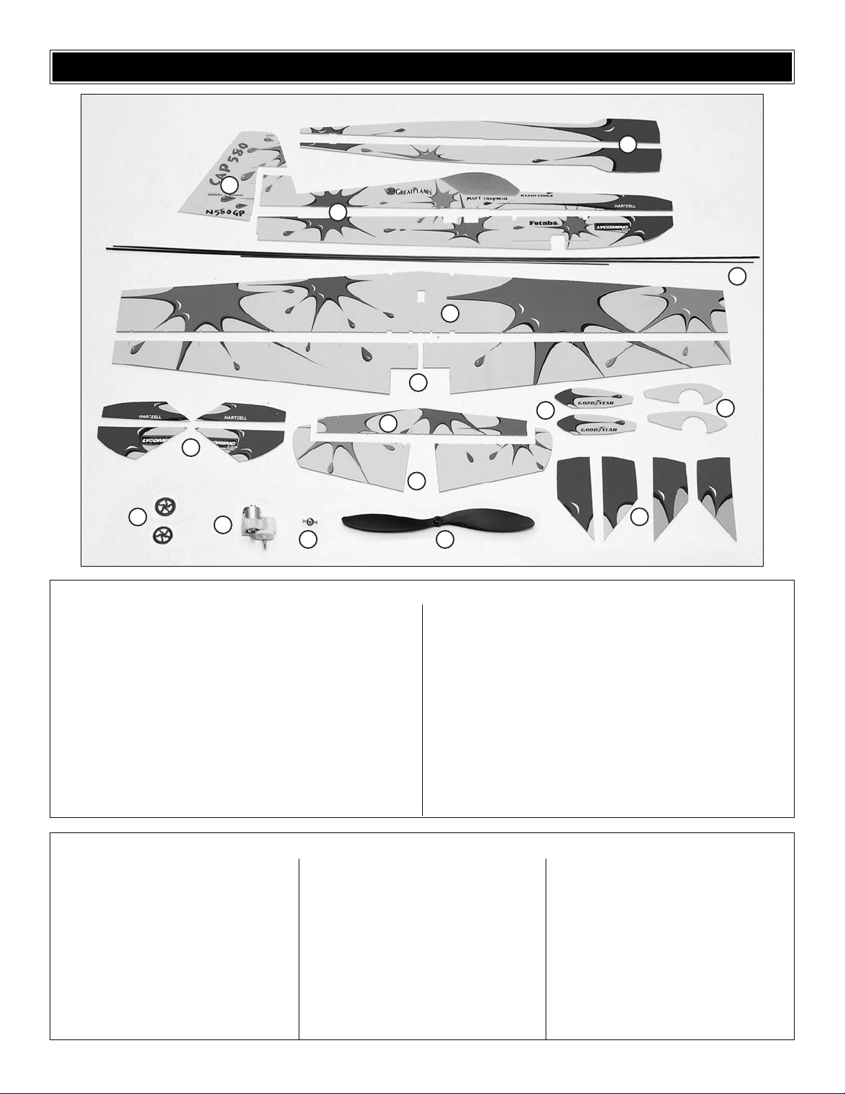
5
1 Horizontal Fuselage Halves (2)
2 Vertical Fuselage Halves (2)
3 Rudder
4 Wing
5 Ailerons (2)
6 Horizontal Stabilizer
7 Elevator Halves (2)
8 Outer Wheel Pants (2)
9 Inner Wheel Pants (2)
10 (Brushless Only) Vertical Fuselage Doublers (4)
11 (Brushless Only) Horizontal Fuselage Doublers (4)
12 Propeller
13 Prop Saver
14 Motor/Gearbox Assembly
15 Main Wheels (2)
16 Carbon Rods and Tubes:
Fuse Doubler Tube 5.5x250mm [7/32" x 9-7/8"]
Elevator Joiner Tube 3x305mm [1/8" x 12"]
Rudder Post Tube 3x108mm [1/8" x 4-1/4"]
Fuselage Tube 3x649mm [1/8" x 25-1/2"]
Leading Edge Tube 3x458mm [1/8" x 18"] (2)
Trailing Edge Tube 3x914mm [1/8" x 36"]
Landing Gear Legs 2x190mm [5/64" x 7-1/2"] (2)
Rear Wing Braces 2x71mm [5/64" x 2-3/4"] (2)
Wheel Axles 2x17mm [5/64" x 5/8"] (2)
Rudder Pushrod 1x325mm [.040" x 12-3/4"]
Elevator Pushrod 1x290mm [.040" x 11-1/2"]
Aileron Pushrods 1x80mm [.040" x 3-1/8"] (2)
Kit Contents (Photographed)
3mm Plywood Firewall
Hook & Loop Mounting Material
O-Rings (2)
Gearbox Motor Block
Plastic Tree Parts:
A1 Z-Bend Clevis (10)
A2 Offset Z-Bend Clevis (4)
B1 Stand-Alone Control Horn (5)
B2 Stand-Alone Control Horn Retainer (5)
C1 Clip Hinge Control Horn (5)
C2 Clip Hinge (26)
C3 Hinge Retainer Ring (10)
C4 Aileron Link Horn (4)
D1 Axle Support (2)
D2 Rod Support (12)
D4 Tailwheel Bracket (1)
D5 Tailwheel (1)
D6 Wheel Collar (2)
E1 Control Surface Brace (4)
E2 Fuselage Joiner (3)
E3 Pushrod Guides (4)
F1 Wire Clip (4)
F2 Wing Servo Mount (1)
F3 Fuselage Servo Mount (2)
F4 Fuselage Aileron Servo Mount (1)
G1 Double-Sided Offset Arm, Size B (2)
G2 Double-Sided Arm, Size B (2)
G3 Single-Sided Arm, Size B (4)
G4 Double-Sided Arm, Size A (2)
G5 Double-Sided Offset Arm, Size A (2)
G6 Single-Sided Arm, Size A (4)
G7 Double-Sided Arm, Size C (2)
G8 Double-Sided Offset Arm, Size C (2)
G9 Single-Sided Arm, Size C (4)
Kit Contents (Not Photographed)
KIT CONTENTS
1
3
2
16
4
5
10
15
14
6
7
1213
8
11
9

6
Replacement Parts List
Or
der Number Description How to Purchase
Missing pieces ................................................Contact Product Support
Instruction manual...........................................Contact Product Support
Full-size plans .................................................Not available
Kit parts listed below.......................................Hobby Supplier
GPMP0217............Gear Drive Body
GPMG0860 ...........Prop Shaft and Spur Gear
GPMG0239 ...........Pinion Gear
GPMG0312 ...........Replacement Motor
APCQ5016 ............10 x 3.8” Propeller
GPMQ4620 ...........Prop Saver
GPMA2794............Hardware Set
GPMG0215 ...........Motor/Gear Drive Assembly
GPMQ4618 ...........Prop Saver O-Ring
ORDERING REPLACEMENT PARTS
Replacement parts for the Great Planes FlatOut CAP 580
ARF are available using the order numbers in the
Replacement Parts List that follows. The fastest, most
economical service can be provided by your hobby dealer or
mail-order company.
To locate a hobby dealer, visit the Hobbico web site at
www.hobbico.com. Choose “Where to Buy” at the bottom
of the menu on the left side of the page. Follow the
instructions provided on the page to locate a U.S., Canadian
or International dealer. If a hobby shop is not available,
replacement parts may also be ordered from Tower
Hobbies®at www.towerhobbies.com, or by calling toll free
(800) 637-6050.
Parts may also be ordered directly from Hobby Services by
calling (217) 398-0007, or via facsimile at (217) 398-7721,
but full retail prices and shipping and handling charges will
apply. Illinois and Nevada residents will also be charged
sales tax. If ordering via fax, include a Visa®or MasterCard
®
number and expiration date for payment.
Mail parts orders and payments by personal check to:
Hobby Services
3002 N Apollo Drive, Suite 1
Champaign IL 61822
Be certain to specify the order number exactly as listed in
the Replacement Parts List. Payment by credit card or
personal check only; no C.O.D.
If additional assistance is required, contact Product Support by
e-mail at productsupport@greatplanes.com, or by telephone
at (217) 398-8970.
Before starting to build, take an inventory of this kit to make sure it is complete, and inspect the parts to make sure they
are of acceptable quality. If any parts are missing or are not of acceptable quality, or if you need assistance with assembly,
contact Product Support. When reporting defective or missing parts, use the part names exactly as they are written in
the Kit Contents list.
Great Planes Product Support:
3002 N Apollo Drive, Suite 1
Champaign, IL 61822
Telephone: (217) 398-8970, ext. 5
Fax: (217) 398-7721
E-mail:
airsupport@greatplanes.com
KIT INSPECTION
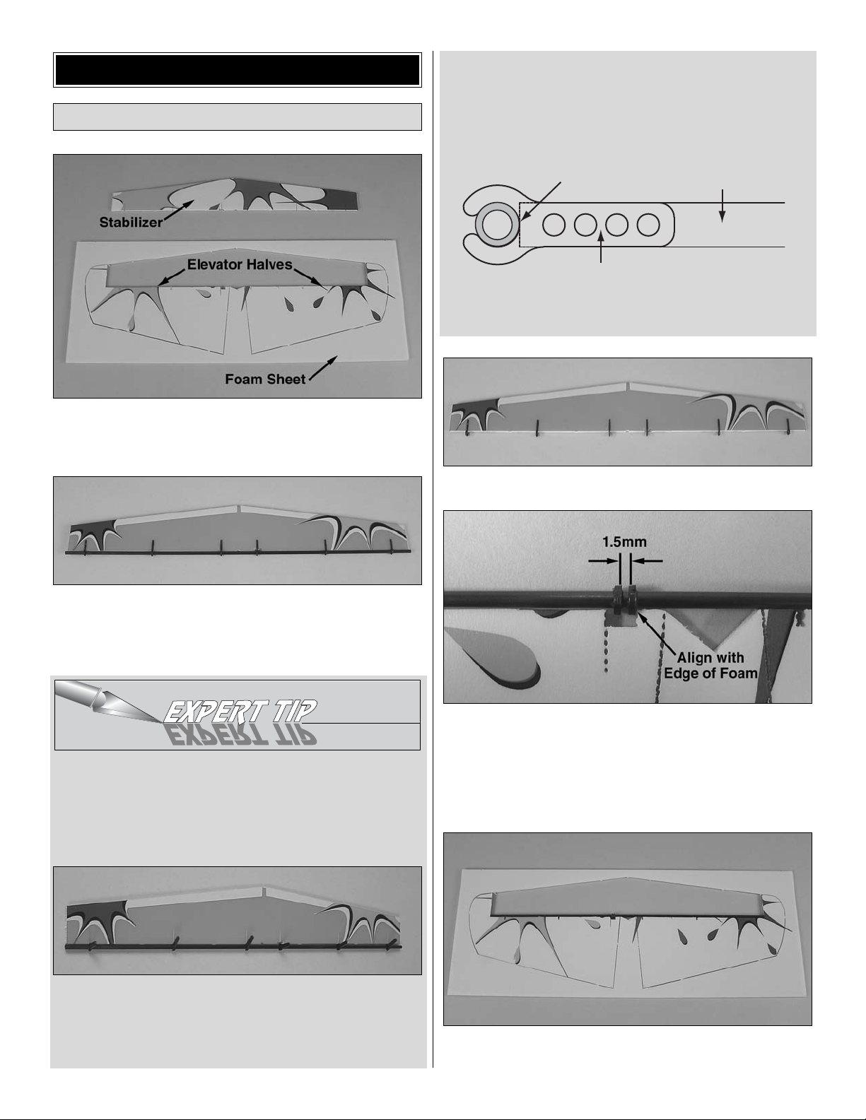
❏ 1. Cut the stabilizer free from the foam sheet with a
sharp
#11 hobby knife.
DO NOT
cut the elevator halves
free at this time.
❏ 2. Following the Expert Tip below, use foam-safe CA and
accelerator to glue six C2 clip hinges into the stabilizer, using
the 3 x 305mm [1/8" x 12"] elevator joiner tube as a guide.
HOW TO INSTALL CLIP HINGES
The clip-hinge system provides a precise, free-moving
hinge. Install all of the clip hinges on this model following the
instructions below.
A. Snap all of the hinges onto the carbon rod. Align the
hinges with the slots.
B. Coat both sides of one hinge with foam-safe CA where it
contacts the sides of the hinge slot. Rotate the hinge down into
the slot. Be certain the top and bottom of the hinge remains
flush with the top and bottom of the control surface you are
hinging. IMPORTANT: Avoid getting any CA on the tube or the
arms of the clips. The clips must rotate freely on the tube.
C. One at a time, coat the sides of each hinge and glue them
into the slots.
❏ 3. Remove the elevator joiner tube from the hinges.
❏ 4. Without removing the elevator halves from the foam
sheet, slide two C3 hinge retainer rings onto the elevator
joiner tube. Align the rings with the cutout in the left elevator
half. There should be a 1.5mm gap between the two rings.
Secure each ring with a drop of glue on the outside of the
gap. Avoid getting glue between the rings.
❏ 5. Following the Expert Tip below, permanently join the
elevator halves by gluing in the elevator joiner tube.
Assemble the Horizontal Tail
BUILD THE AIRPLANE
7
Carbon Tube
(Snug Against
Control Surface)
Hinge Centered
in Surface
Control Surface
HOW TO GLUE THE TUBES TO THE CONTROL SURFACES
NOTE: You may want to protect your work surface from
excess glue. We recommend Great Planes Plan Protector
(GPMR6167) for this purpose.
A. Cut several 1-1/2" pieces of tape. Fold the last 1/4" over
to make a tab for easy removal.
B. Coat the edge of the foam with foam-safe CA–do not use
an excessive amount of glue. Hint: A CA applicator tip is
recommended to accurately control the bead of glue.
C. Use the tape pieces to hold the tube against the foam
edge. Weigh the parts down on a flat surface to prevent
warping and allow the glue to cure without accelerator.
D. Once the glue has cured, remove the tape.
❏ 6. Cut the elevator halves free of the sheet.
❏ 7. Join the elevators to the stab by snapping the clip
hinges to the joiner tube.
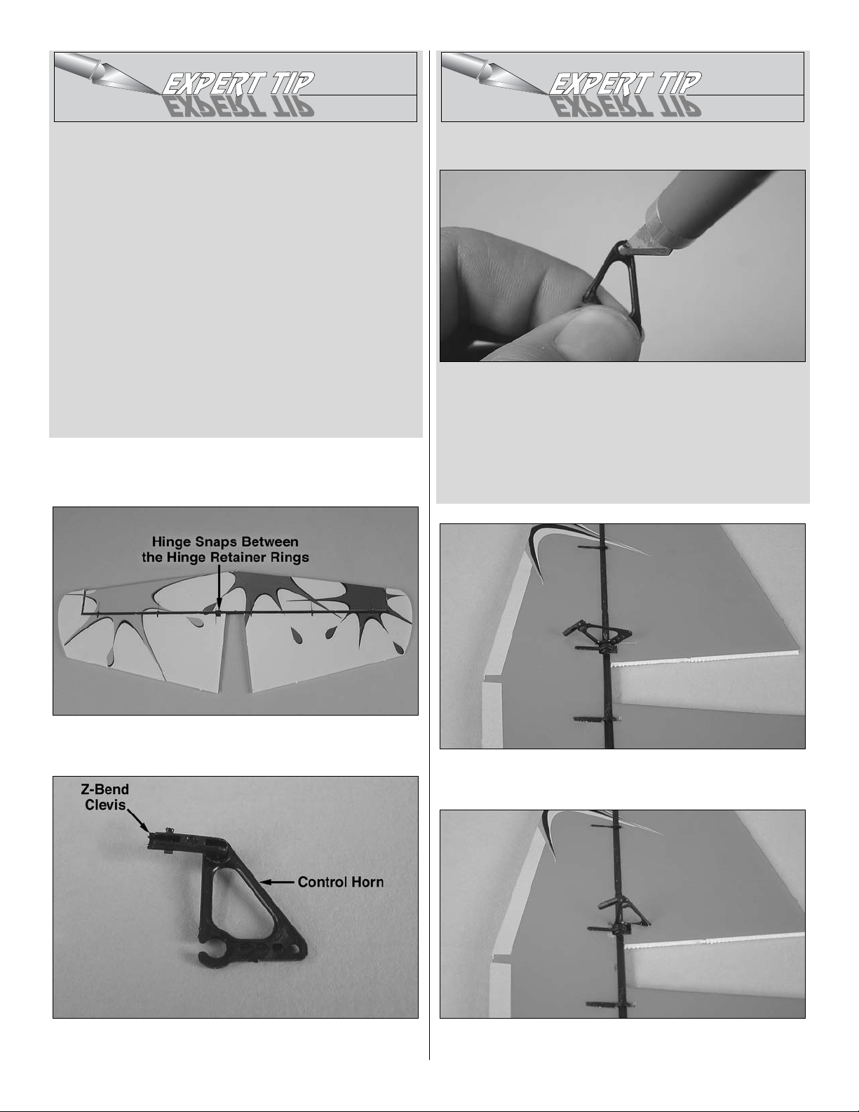
❏ 8. Insert an A1 Z-bend clevis into a C1 clip-hinge
control horn.
HOW TO MAKE INSTALLING Z-BEND CLEVISES EASIER
A. Using a sharp #11 hobby knife, remove any flashing from
the inside of the hole you are installing the Z-bend into. Do
this by rotating the blade in the hole while applying gentle
pressure. Be careful not to remove too much material–your
goal here is to remove small ridges of flashing, not to make
the hole bigger.
B. Snap the Z-bend clevis into place.
❏ 9. Clip the control horn onto the joiner tube aligned with
the precut slot.
❏ 10. Coat the gluing area on the control horn with glue and
rotate it down into the precut slot.
8
 Loading...