

Page 1
WARRANTY
Great Planes®Model Manufacturing Co. guarantees this kit to be free from defects in both material and workmanship at the date of purchase.This
warranty does not cover any component parts damaged by use or modification.In no case shall Great Planes’ liability exceed the original cost of
the purchased kit. Further, Great Planes reserves the right to change or modify this warranty without notice.
In that Great Planes has no control over the final assembly or material used for final assembly, no liability shall be assumed nor accepted for any
damage resulting from the use by the user of the final user-assembled product. By the act of using the user-assembled product, the user accepts all
resulting liability.
If the buyer is not prepared to accept the liability associated with the use of this product, the buyer is advised to return this kit immediately
in new and unused condition to the place of purchase.
READ THROUGH THIS MANUAL BEFORE STARTING
CONSTRUCTION. IT CONTAINS IMPORTANT
INSTRUCTIONS AND WARNINGS CONCERNING THE
ASSEMBLY AND USE OF THIS MODEL.
GPMZ0208 for GPMA1110 V1.0 Entire Contents © Copyright 2003
Champaign, IL
(217) 398-8970, Ext. 5
airsupport@greatplanes.com
INSTRUCTION MANUAL
Wingspan: 31-3/8 in [795mm]
Wing Area: 312 sq in [20.1 dm
2
]
Canard Area: 64 sq in [4.1 dm
2
]
Weight: 11.6 oz [330 g]
Wing Loading: 4.5 oz/sq ft [13.7 g/dm
2
]
Length: 24.5 in [622mm]
Radio: 3-channel with 2 micro servos
ALMOST READY TO FLY ELECTRIC POWERED R/C AIRPLANE
Page 2
INTRODUCTION ..........................................................................2
SAFETY PRECAUTIONS.............................................................2
ADDITIONAL ITEMS REQUIRED................................................3
Flight Equipment....................................................................3
Building Supplies...................................................................3
IMPORTANT BUILDING NOTES.................................................3
KIT CONTENTS...........................................................................4
ORDERING REPLACEMENT PARTS .........................................5
BUILDING INSTRUCTIONS.........................................................6
Install the Bottom Wing..........................................................6
Install the Top Wing...............................................................7
Install the Servos...................................................................8
Install the Canards ..............................................................10
Install the Rudders ..............................................................11
Final Assembly....................................................................11
GET THE MODEL READY TO FLY............................................11
Check the Control Directions...............................................11
Set the Control Throws........................................................12
Balance the Model (C.G.) ....................................................12
PREFLIGHT ...............................................................................13
Identify Your Model..............................................................13
Charge the Transmitter Batteries .........................................13
Ground Inspection...............................................................13
Range Check .......................................................................13
Perf ormance Tips.................................................................13
Motor Safety Precautions....................................................14
AMA SAFETY CODE (excerpt).................................................14
FIND A SAFE PLACE TO FLY...................................................14
FLYING .......................................................................................15
Takeoff .................................................................................15
Flight....................................................................................15
Landing................................................................................15
Thank you for purchasing the Great Planes Wright Flyer
ARF.The Wright Flyer ARF is a lightweight, fun scale model
of the historic Wright Flyer, the first successful powered
aircraft.
While the original Wright Flyer first flew in 1903, it was not
until 1905 that the Wright brothers developed an improved
version of the aircraft.This improved aircr aft solved many of
the problems found on the 1903 Flyer.This model is based
on the 1905 Wright Flyer.
The Wright Flyer ARF is a slow flying model that is ideal for
park flying. It is stable and easily maneuvered.The original
Wright Flyer was not aerobatic and this model isn’t either.
For the latest technical updates or manual corrections to the
Wright Flyer visit the Great Planes web site at
www.greatplanes.com
. Open the “Airplanes” link, then
select the Wright Flyer ARF. If there is new technical
information or changes to this model a “tech notice”box will
appear in the upper left corner of the page.
Attention: The product you have purchased is powered by
a rechargeable battery. At the end of its useful life, under
various state and local laws, it may be illegal to dispose of
this battery into the municipal waste system. Check with
your local waste officials for details in y our area f or recycling
options or proper disposal.
This product contains a chemical known to the State of
California to cause cancer and birth defects or other
reproductive harm.
1. Although the Great Planes Wright Flyer is a light weight
electric powered model, just the same as any R/C plane, it
should still be flown with care.The Wright Flyer should not
be considered a toy, but rather a sophisticated, working
model that functions very much like a full-size airplane. If
not assembled and operated correctly, the Wright Flyer
could possibly cause injury to yourself or spectators and
damage property.
2. You must assemble the Wright Flyer according to the
instructions. Do not alter or modify the model, as doing so
may result in an unsafe or unflyable model. In a few cases
the instructions may differ slightly from the photos.In those
instances the written instructions should be considered as
correct.
3.You must take the time to build straight,true and
strong.
4. You must use an R/C radio system that is in first-class
condition.
5.You must correctly install all R/C and other components
so that the model operates correctly on the ground and in
the air.
6.You must check the operation of the model before every
flight to insure that all equipment is operating and that the
model has remained structurally sound. Be sure to check
clevises or other connectors often and replace them if they
show any signs of wear or fatigue.
7. If you are not already an experienced R/C pilot, you
should fly the model only with the help of a competent,
experienced R/C pilot.
PRO TECT YOUR MODEL,YOURSELF
& OTHERS...FOLLOW THESE
IMPORTANT SAFETY PRECAUTIONS
INTRODUCTION
TABLE OF CONTENTS
2
Page 3
Remember: Take your time and follow the instructions
to end up with a well-built model that is straight and
true.
If you have not flown this type of model before, we
recommend that you get the assistance of an experienced
pilot in your R/C club for your first flights. If you’re not a
member of a club, your local hobby shop has information
about clubs in your area whose membership includes
experienced pilots.
In addition to joining an R/C club, we strongly recommend
you join the AMA (Academy of Model Aeronautics). AMA
membership is required to fly at AMA sanctioned clubs.
There are over 2,500 AMA chartered clubs across the
country .Among other benefits, the AMA provides insurance
to its members who fly at sanctioned sites and events.
Additionally, training programs and instructors are available
at AMA club sites to help you get started the right way.
Contact the AMA at the address or toll-free phone number
that follows:
The Wright Flyer requires a three-channel radio with two
micro servos and a small receiver. Radio equipment
designed for park flyer models can be used. The servos
should have a minimum of 8 oz-in torque.
Suggested Servos:
(HCAM0090) CS-5, 16.7 oz-in torque
(HCAM0100) CS-15, 15 oz-in torque
(FUTM0037) S3103, 17.3 oz-in torque
(FUTM0041) S3106, 16.7 oz-in torque
(HRCM0984) HS-50J, 8.4 oz-in torque
(HRCM0981) HS-55J, 15 oz-in torque
Suggested Receivers:
(GPML0044) 4-channel FM, low band
(GPML0045) 4-channel FM, high band
(FUTL0442) 4-channel FM, low band
(FUTL0443) 4-channel FM, high band
low band - channels 11-35
high band - channels 36-60
Receiver Crystal:
(FUTL62**) for GPM low band
(FUTL63**) for GPM high band
(FUTL62**) for FUT low band
(FUTL63**) for FUT high band
**= desired channel
A 7-cell (8.4 volt) 300 mAh NiMH battery pack and speed
control are included.
For charging the battery at the flying field, the Great Planes
ElectriFly
™
Peak Charger (GPMM3000) is recommended.
The Great Planes ElectriFly Triton™Computerized Charger
(GPMM3150) is recommended for shop charging and
discharging.
In addition to common household tools and hobby tools, this
is the list of items used to build the Wright Flyer.
Great
Planes Pro™CA and Epoxy glue are recommended.
❏ 6-minute Epoxy (GPMR6042)
❏ Hobby knife (HCAR0105)
❏ #11 Blades (HCAR0211)
❏ Double-sided foam tape (GPMQ4440, for mounting
receiver)
❏ Sandpaper and sanding block
❏ Small Phillips screwdriver (#1)
• Since the Wright Flyer is made mostly of foam, and CA
adhesives commonly used to build R/C model airplanes
dissolve foam, CA should not be used when gluing foam
parts. Therefore, 6-minute epoxy, which is compatible with
foam, is used for construction.Unless otherwise specified in
the instructions, 6-minute epoxy is to be used for gluing all
parts of the model together.
• For the strongest bond apply epoxy to both parts
being joined.
• Photos and sketches are placed before the step they
refer to. Frequently you can study photos in following steps
to get another view of the same parts.
• The canard and wing incidence angles have been
factory-built into this model and cannot be changed.
IMPORTANT BUILDING NOTES
Building Supplies
Flight Equipment
ADDITIONAL ITEMS REQUIRED
Academy of Model Aeronautics
5151 East Memorial Drive
Muncie, IN 47302
Tele: (800) 435-9262
Fax (765) 741-0057
Or via the Internet at:
http://www.modelaircraft.org
Note: We, as the kit man ufacturer , provide you with a top
quality, thoroughly tested kit and instructions, but
ultimately the quality and flyability of your finished model
depends on how you build it;therefore, we cannot in any
way guarantee the performance of your completed
model, and no representations are expressed or implied
as to the performance or safety of your completed model.
3
Page 4
4
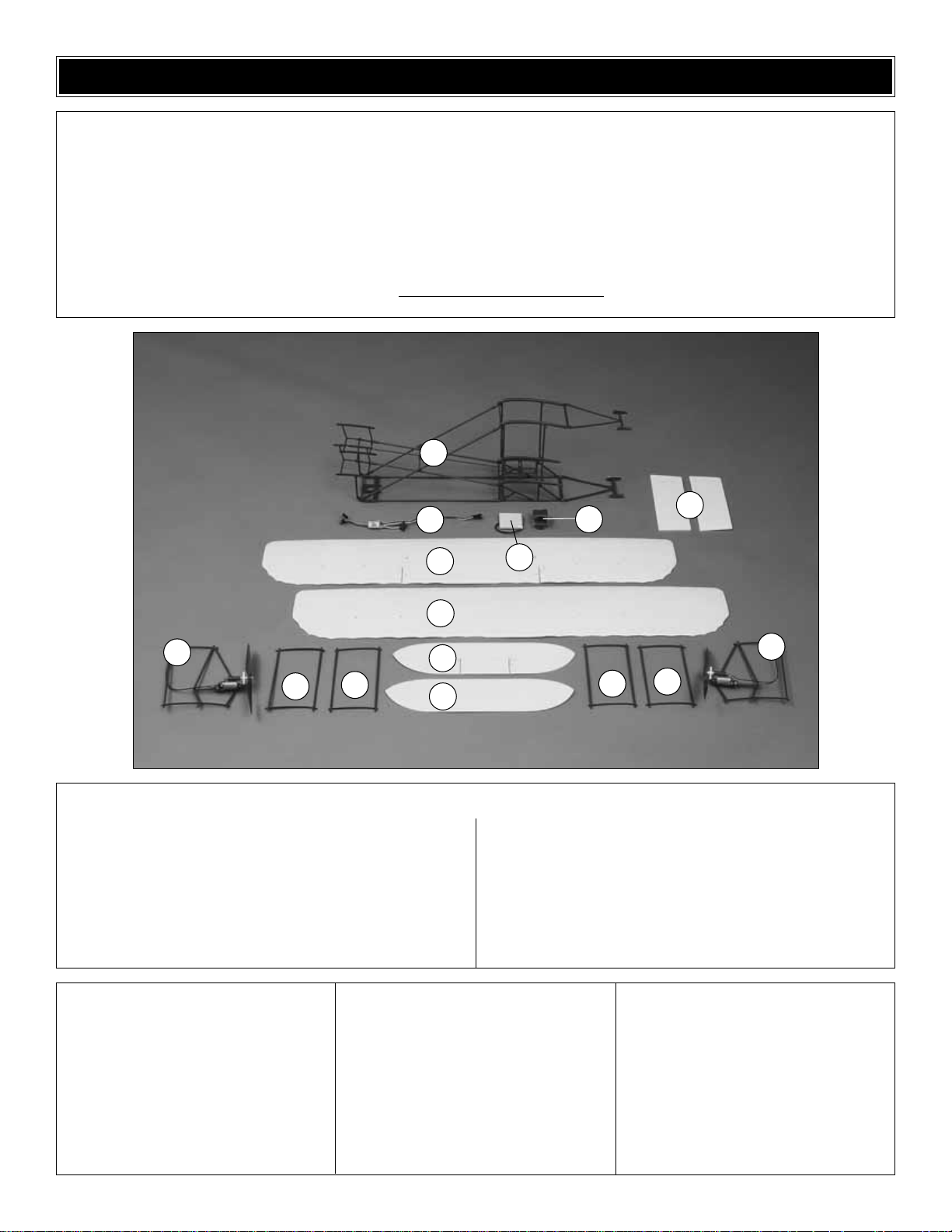
1 Fuselage
2 Bottom Wing
3 Top Wing
4 Bottom Canard
5 Top Canard
6 Rudders (2)
7 Left Motor and Wing Support
8 Right Motor and Wing Support
9 Center Struts (2)
10 Outer Str uts (2) with Notch
11 Speed Control
12 Batter y Pack 300 mAh
13 Receiver Box
Kit Contents (shown above)
Before starting to build, take an inventory of this kit to make sure it is complete, and inspect the parts to make sure they are of
acceptable quality. If any parts are missing or are not of acceptable quality, or if you need assistance with assembly, contact
Product Support.When reporting defective or missing parts, use the part names exactly as they are written in the Kit Contents
list on this page.
Great Planes Product Support:
3002 N. Apollo Drive, Suite 1
Champaign, IL 61822
Telephone: (217) 398-8970, Ext. 5
Fax: (217) 398-7721
E-mail:
airsupport@greatplanes.com
KIT CONTENTS
(2) Long String
(2) Shor t String
(4) Nylon Control Hor n
(1) Nylon Torque Rod Horn
(8) 2-56 x 3/8" [9.6mm] Screw
(1) Plastic Servo Cover
(2) #2 x 1/4" [6.4mm] Screw
(1) 2-56 Hex Nut
(1) 2-56 Clevis
(1) 4-3/8" [111mm] Elevator Horn Wire
(2) 1-3/4" [44.5mm] Plastic Spacer
(2) Shor t Pushrod
(2) Long Pushrod
(24)Plastic Strut Clips
(2) Plastic Bellcrank
(2) Plastic Bellcrank Standoff
(1) Pilot Figure
Kit Contents (not shown)
1
2
4
7
8
6
3
10
10
11
5
9
9
12
13
Page 5
5
To order replacement parts for the Great Planes Wright Flyer ARF, use the order numbers in the Replacement P arts List
that follows.Replacement par ts are available only as listed. Not all parts are available separately. Replacement parts are
not available from Product Support, but can be purchased from hobby shops or mail order/Internet order firms. Hardware
items (screws, nuts, bolts) are also a vailab le from these outlets.If you need assistance locating a dealer to purchase parts,
visit
www.greatplanes.com
and click on “Where to Buy.” If this kit is missing parts, contact Product Support.
Replacement Parts List
Order Number Description How to Pur
chase
Missing pieces Contact Product Support
Instruction manual Contact Product Support
Full-size plans Not available
GPMA2560 Wing Set (2)
GPMA2561 Fuselage
GPMA2569 Stabilizer Set (2)
GPMA2562 Rudder Support (2)
GPMA2563 Rudder Set (2)
GPMA2564 Outer & Center Wing Struts (4)
GPMA2565 Inner Wing Struts w/Motor Mounts (2)
GPMA2566 Motor Mounts (2)
GPMG0293 Motor
GPMA2567 Propeller
GPMA2568 Strut Clip (24)
GPMP1980 Speed Control
GPMP0064 Battery Pack 300 mAh (8.4 volt) NiMH
ORDERING REPLACEMENT PARTS
.............
Contact Your Hobby
Supplier to Purchase
These Items
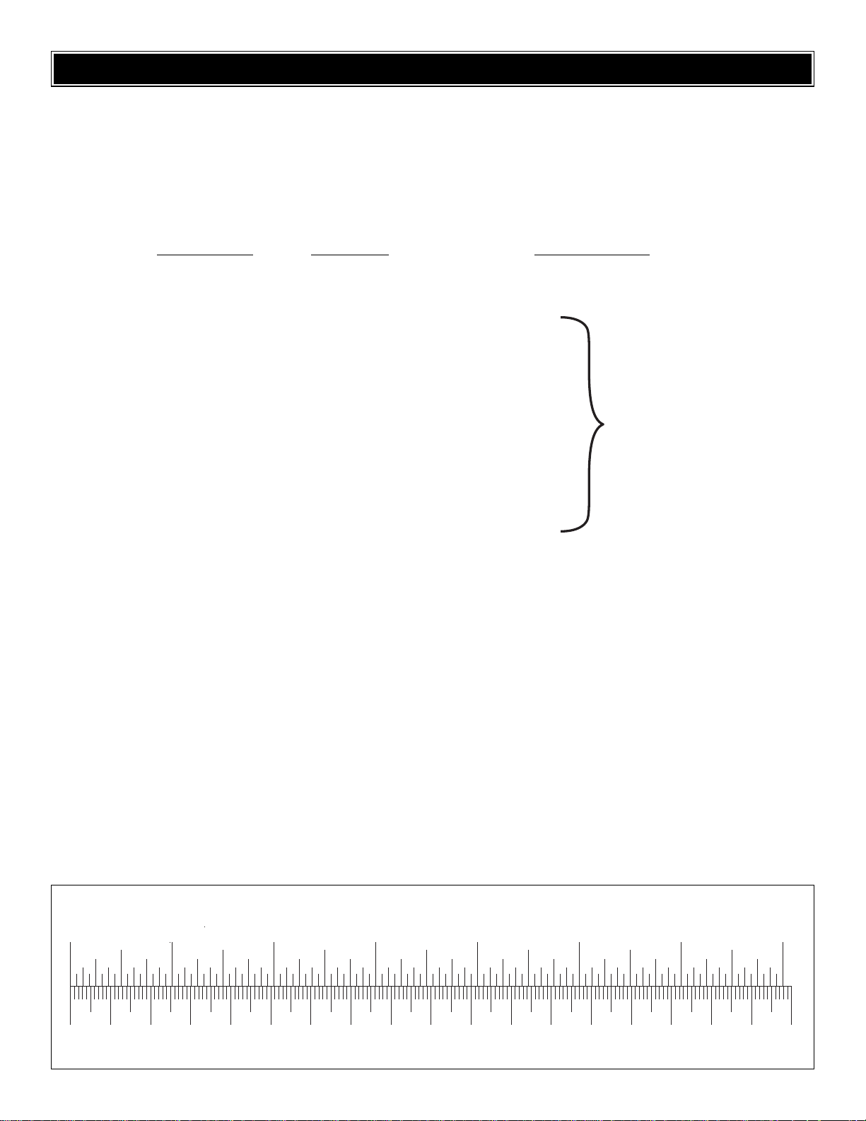
0" 1" 2" 3" 4" 5" 6" 7"
0 10 20 30 40 50 60 70 80 90 100 110 120 130 140 150 160 170 180
Inch Scale
Metric Scale
To convert inches to millimeters, multiply inches by 25.4
Page 6

❏ 1. The above photo shows the bottom of the bottom
wing.Install a nyloncontrol horn on the bottom of the right
aileron with two 2-56 x 3/8" [9.6mm] machine screws and
the nylon backplate. Do not tighten the screws too much.
The holes in the control horn for the clevis should face
forward.Do not install a control hor n on the left aileron until
instructed to do so.
❏ 2. The aileron is self-hinged to the wing. Cut the foam
material along the lines shown in the photo to allow the
ailerons to move more freely. Cut the other aileron hinge in
the same manner. Note: Only the bottom wing surface has
operating ailerons.
❏ 3. Star ting with the left tip of the bottom wing, inser t the
wing into the fuselage frame. Note that the bottom of the
fuselage structure is flat along the length of the fuselage.
Remember that this is a canard model with the ailerons
facing the rear of the model.
Caution: Be careful not to damage the foam wing as it is
inserted into the fuselage.
❏ 4. Install a control horn on the bottom of the left aileron.
❏ 5. Make sure the wing is centered in the fuselage frame.
Note in the photo that the centerline of the wing is aligned
with the center of the servo openings.
Install the Bottom Wing
BUILDING INSTRUCTIONS
6
Page 7

❏ 6. Cut the holes for the servos into the bottom wing.Use
the fuselage frame as a guide.The photos above show the
top and bottom of the wing.
❏ 7. Cut slots for mounting the receiver box, if you will be
using it. These holes can be seen to the right of the servo
holes in the top photo.(See page 11, step 1.)
Note: If your receiver is too large for the receiver box, use
double-sided tape to hold the receiver in place.
In the following steps the top wing will be installed with six
struts that hold the two wings in position. There are three
types of struts; one with a motor attached, one with notches
in the rear end and one with no notches.In addition, the top
and bottom of each strut has a curved airfoil shape. The
more curved end of this airfoil faces the front of the model.
It is important that these struts are installed correctly in the
following steps.
❏ 1. Install the str uts in the bottom wing as shown in the
photo above.Notice that the motors on the inner struts face
the inside of the model.The outer struts have a notch in the
rear edge at the top and bottom of the strut. This notch is
used to attach a string in a later step. This notch can be
seen in the photo for step 3.
❏ 2.Before completing this step refer to steps 3, 4 and 5 to
be sure that the struts are installed correctly and that the
notches in the outer struts are aligned so that the str ings
will align with the posts on the fuselage. Once you are
certain the struts are installed correctly, use a white plastic
strut clip to hold the ends of the struts to the wing.Two clips
are required for each strut.
Note:The clips can be hard to install. Hold the strut carefully
with one hand while pressing the clip onto the end of the
strut with the other hand.Use the tips of two fingers near the
center of the clip and push the clip while rocking it into
place. Do not use a tool.If you slip you could poke a hole in
the wing.
Install the Top Wing
7
Page 8

❏ ❏ 3. The above photo shows the outer strut on the left
bottom wing where it attaches to the wing at the trailing
edge. Notice the notch in the strut. Locate a short string
and slide one end under the rear edge of the strut and onto
the notch.The other end of the string will be attached in the
next step.
❏ ❏ 4.Guide the other end of the string through the motor
strut and onto the post at the top of the fuselage upright.
In the same manner, attach the other short string to the right
side of the wing.
❏ ❏ 5. Using the same technique, install a long string
from the notch at the top of each outer strut to the post at
the bottom of the fuselage uprights on the left and right
sides of the wing.
❏ 6. Install the top wing by sliding it into the slots in the top
of the fuselage uprights. Be careful to guide it along the top
of the wing struts.When the top wing is in place, check that
it is centered in the fuselage.The bottom of the wing has the
centerline marked on it.
❏ 7.Insert the tops of the wing struts in the proper holes in
the top wing.Once certain the top wing is installed correctly,
use white plastic strut clips to hold the ends of the struts to
the wing.Two clips are required for each strut.
❏ 1. Install the servos in the fuselage frame from the
bottom of the bottom wing using the grommets, brass
eyelets and screws supplied with your servos.
Note: Where the two servos meet, you will be able to use
only one grommet, brass eyelet and screw. A white plastic
cover is included to hold the grommet and servos in place
(as shown in the photo that follows).
Install the Servos
8
Page 9

❏ 2.Install a plastic bellcrank on the right motor strut post
extending below the bottom of the bottom wing, using a
plastic standoff and 2mm x 8mm wood screw. If required,
enlarge the hole in the bellcrank with a 5/64" [2mm] drill bit
so that the screw slides freely into the hole.
Install the bellcrank with the flange on the plastic standoff
against the wing.The long ar m of the bellcrank should face
forward and the short arm should face the wing tip. Do not
install the screw until the next step.
❏ 3. Install a short aileron pushrod wire connecting the
short arm of the bellcrank to the aileron control hor n. The
wire should be inserted in the outer hole on the bellcrank
and the second hole closest to the wing on the control horn.
Install the 2mm x 8mm screw on the bellcrank. Do not
overtighten the screw.
❏ 4. Install a long aileron pushrod wire connecting the
long arm of the bellcrank to the servo arm. The wire should
be inserted in the second hole from the end on the bellcrank
and the outer hole on the longest arm of the servo horn. Do
not install the screw holding the servo horn to the servo until
the next step.
❏ 5. In the same manner, install the left aileron bellcrank,
plastic standoff, 2mm x 8mm wood screw and pushrods to
the left aileron.The long arm of the bellcrank should face aft
as shown in the photo above. Install the ser vo horn on the
servo and secure it with the horn screw supplied with
the servo.
❏ 6.Insert the elev ator pushrod into the outer hole on the
longest arm of the elevator servo horn.Install the serv o horn
on the servo and secure it with the horn screw supplied with
the servo.
9
Page 10

❏ 1.Assemble the elevator horn linkage.Slide a nylon
torque
rod horn onto the 1/16" x 4-3/8" [1.6 x 111mm] unthreaded
wire. Slide a 1-3/4" [44mm] brown plastic tube onto the
wire on each side of the torque rod horn.
❏ 2. The top canard has the elevators molded into it.
Install a nylon control horn on the bottom of the right
elevator with two 2-56 x 3/8" [9.5mm] machine screws and
the nylon backplate. Do not tighten the screws too much.
The holes in the control horn for the clevis should face
forward. Do not install a control horn on the left elevator.
Note: Before mounting the horn, drill out the two middle
clevis holes in the control horn with a 5/64" [2mm] drill bit.
❏ 3.Inser t the top canard into the fuselage frame. The
photo
shown above and the following photo have been taken from
the
bottom of the model.The elev ator faces the rear of the
model.
❏ 4. Inser t one end of the elevator horn linkage into the
right elevator horn already mounted on the elevator. It
should be inserted into the second hole closest to the
elevator. Insert the other end of the elevator horn linkage
into the same hole of another nylon control horn. Install this
control horn on the left elevator with two 2-56 x 3/8" [9.5mm]
machine screws and a nylon backplate.
❏ 5.Thread a 2-56 hex nut and 2-56 metal clevis onto the
elevator pushrod already installed in the fuselage frame.
Connect the clevis to the elevator control horn. Be sure to
tighten the hex nut against the clevis after it has been
adjusted properly.
❏ 6. Insert the bottom canard into the fuselage frame.
Before installing it, check that the shape and alignment will
match the top canard. Note: Only the top stabilizer has
operating elevators.
Install the Canards
10
Page 11

❏ 1.The rudders can be attached with the included double-
sided tape or with 6-minute epoxy. Do not use CA adhesive
as it will damage the foam rudder.The double-sided tape will
allow the rudder to pop off if it hits an object. The above
photo shows only the left rudder in place.
1. Install the receiver box on the top of the bottom wing.
Install your receiver in the receiver box. The above photo
shows a Futaba®R114F receiver. For this installation it was
necessary to trim some of the plastic to clear the serv o
leads.
❏ 2.The Electronic Speed Control (ESC) can be secured
to one of the fuselage cross braces with a small nylon
tie-wrap. Plug the motor wires into the ESC. Note that the
motor wires have also been secured with tie-wraps. The
switch can be held in place with 6-minute epo xy or thic k CA.
❏ 3. Secure the battery in the battery holder under the
canards with the rubber bands provided.
❏ 4.Route the battery wire to the wire from the ESC, which
has been secured with a tie-wrap.
❏ 5.The receiver antenna can be routed along the sides of
the fuselage, around the front and secured with clear tape.
IMPORTANT: Whenever connecting the battery, always
hold onto the fuselage incase the motors accidentally
receive power and the propellers turn.
❏ 1. Turn on the transmitter, connect the battery to the
speed control and turn the receiver on. Center the trims on
the transmitter. If necessary, remove the servo horns from
the servos and reposition them so they are centered.
Reinstall the screws that hold on the servo horns.
❏ 2. With the transmitter and receiver still on, check all the
control surfaces to see if they are centered. If necessary,
adjust the clevises and pushrods to center the control
surfaces.
❏ 3. Be cer tain the ailerons, elevator and motors respond
in the correct direction as shown in the diagram that follows.
If any of the controls respond in the wrong direction, use the
reversing in the transmitter to reverse the servos connected
to those controls. Be certain the control surfaces have
remained centered. Adjust if necessary.
Check the Control Directions
GET THE MODEL READY TO FLY
Final Assembly
Install the Rudders
11
Page 12

IMPORTANT: Remember that this model is equipped with
canards.When the elevator stick is pulled back toward you,
the canard elevator will deflect downwards.
Use a ruler to accurately measure and set the control
throws of each control surface as indicated in the chart that
follows. If your radio does not have dual rates, we
recommend setting the throws at the high rate setting.
Use the ATV function in the transmitter or adjust the position
of the pushrods on the servo arms or the control horns on
the elevators and ailerons to get the control surface throws
shown in the chart that follows.The throws are measured at
the widest part of the control surface.
To increase the control surface throw, move the pushrod to
the hole that is closer-in on the control horn on the control
surface, or move the pushrod to the hole that is farther out
on the servo arm.To decrease the control surface throw, do
the opposite.
The C.G.(center of gravity) must be checked with the model
in ready-to-fly condition with all of the systems in place and
the battery installed.
❏ 1.Use a felt-tip pen or narrow strips of tape to accurately
mark the C.G.on the bottom of the lower fuselage rails.The
C.G. is located 1-1/8" [28.6mm] in front
of the bottom wing.
Remember, this is a model with lifting canards, so the
balance point will be in front of the wings.
IMPORTANT: This model is very sensitive to the proper
C.G. It must be balanced exactly as shown or the model
may not fly well. The C.G. range of this model is very
limited and only very minor changes should be made.
IMPORTANT: The C.G. (center of gravity), or balance
point has the greatest effect on how a model flies. Do not
overlook this important procedure. Modelers who do so
often find that the airplane is difficult to control, or out of
control after it is too late.Preserve your model and insure
that the first flight won’t be the last by balancing the model
according to the following instructions.
Balance the Model (C.G.)
IMPORTANT: The Wright Flyer has been extensively
flown and tested to arrive at the throws at which it flies
best. Flying your model at these throws will provide you
with the greatest chance for successful first flights.If, after
you have become accustomed to the w a y the Wright Flyer
flies, you would like to change the throws to suit your
taste, that is fine. However, too much control throw could
make the model difficult to control, so remember , “more is
not always better.”
Set up the Wright Flyer so it has the following control
surface throws:
ELEVATOR:
High Rate 5/8" [16mm] up and down
Low Rate 1/4" [6.4mm] up and down
AILERONS:
High Rate 5/8" [16mm] up and down
Low Rate 3/8" [10mm] up and down
Set the Control Throws
Note: Unless you are specifically checking the operation
of the motor, for safety remove the propellers from the
model while setting it up on your workbench.
12
Page 13

❏ 2. Lift the model, upside-down, at the balance point you
marked on fuselage rails.This is easiest to do with a piece
of wire or the edge of a ruler.
❏ 3. If the tail drops, the model is “tail heavy” and the
battery pack and/or receiver must be shifted forward or
weight must be added to the nose to balance. If the nose
drops, the model is “nose heavy” and the battery pack
and/or receiver must be shifted aft or weight must be added
to the tail to balance. If possible, relocate the battery pack
and receiver to minimize or eliminate any additional ballast
required. If additional weight is required, use Great Planes
(GPMQ4485) “stick-on”lead. If weight is required in the tail,
it
can be stuck to the bottom of the rudder support. If weight
is
required in the nose it can be attached to the battery holder.
❏ 4. IMPORTANT: If you found it necessary to add any
weight, recheck the C.G.after the weight has been added to
confirm that it is correct.
Our prototype model required 1/8 ounce [3.5 grams] on the
front of the model.
No matter if you fly at an AMA sanctioned R/C club site or if
you fly somewhere on your own, you should always have
your name, address, telephone number and AMA number
on or inside your model. It is required at all AMA R/C club
flying sites and AMA sanctioned flying events. Fill out the
identification tag on the back cover page and place it on or
inside your model.
Be certain the transmitter batteries are fully charged. Follow
the battery charging instructions that came with your radio
control system to charge the batteries. You should always
charge your batteries the night before you go flying, and at
other times as recommended by the radio manufacturer.
Before you fly y ou should perform one last ov erall inspection
to make sure the model is truly ready to fly and that you
haven’t overlooked anything. If you are not thoroughly
familiar with the operation of R/C models, ask an
experienced modeler to perform the inspection. Check to
see that you have the radio installed correctly and that all
the controls are connected properly. The motors must also
be checked by confirming that the props are rotating in the
correct direction and the motors sound like they are
reaching full power. Make certain the ailerons and elevators
are secure, the pushrods are connected, the controls
respond in the correct direction, radio components are
securely mounted, and the C.G. is correct.
Ground check the operational range of your r adio bef ore the
first flight of the day. With the transmitter antenna collapsed
and the receiver and transmitter on, you should be able to
walk at least 100 feet away from the model and still have
control. Have an assistant stand by your model and, while
you work the controls, tell you what the control surfaces are
doing. Repeat this test with the motors running at various
speeds with an assistant holding the model, using hand
signals to show you what is happening. If the control
surfaces do not respond correctly, do not fly! Find and
correct the problem first. Look for loose servo connections
or broken wires, corroded wires on old servo connectors,
poor solder joints in your battery pack or a defective cell, or
a damaged receiver crystal from a previous crash.
• Use fine sandpaper to remove imperfections along the
edges of the propeller. For the best performance, use a
Top Flite®Precision Magnetic Prop Balancer
™
(TOPQ5700) to balance the propellers (this is a necessity
on glow-powered engines, but less critical on small
electric models).
• Using multiple battery packs for successive flights may
cause the motors to become excessively hot, thus
causing damage. Allow the motors to cool for at least 10
minutes between flights.
Perf ormance Tips
Range Check
Ground Inspection
Charge the Transmitter Batteries
Identify Y our Model
PREFLIGHT
13
Page 14

Get help from an experienced pilot when learning to
operate motors.
Use safety glasses when running motors.
Do not run the motors in an area of loose gravel or sand;the
propellers may throw such material in your face or eyes.
Keep your f ace and body as well as all spectators a wa y from
the plane of rotation of the propellers as you start and run
the motors.
Keep these items away from the props: loose clothing, shirt
sleeves, ties, scarfs, long hair or loose objects such as
pencils or screwdrivers that may fall out of shirt or jacket
pockets into the props.
The electric motors and motor battery used in the Wright
Flyer are powerful and the spinning propellers have a lot of
momentum; therefore, if you touch a propeller while it is
spinning it may inflict severe injury. Respect the motors and
propellers for the damage they are capable of and take
whatever precautions are necessary to avoid injury.Always
disconnect and remove the motor battery until you are ready
to fly again and always make sure the switches are turned
off before connecting the battery.
Read and abide by the following Academy of Model
Aeronautics Official Safety Code:
GENERAL
1. I will not fly my model aircraft in sanctioned events, air
shows, or model flying demonstrations until it has been
proven to be airworthy by having been previously
successfully flight tested.
2. I will not fly my model aircraft higher than approximately
400 feet within 3 miles of an airport without notifying the
airport operator.I will give right of way to, and avoid flying in
the proximity of full-scale aircraft. Where necessary an
observer shall be used to supervise flying to avoid having
models fly in the proximity of full-scale aircraft.
3.Where established, I will abide by the safety rules for the
flying site I use, and I will not willfully and deliberately fly my
models in a careless, reckless and/or dangerous manner.
7. I will not fly my model unless it is identified with my name
and address or AMA number, on or in the model.
9. I will not operate models with pyrotechnics (any device
that explodes, burns, or propels a projectile of any kind).
RADIO CONTROL
1.I will have completed a successful radio equipment
ground
check before the first flight of a new or repaired model.
2. I will not fly my model aircraft in the presence of
spectators until I become a qualified flyer, unless assisted
by an experienced helper.
3. I will perform my initial turn after takeoff away from the pit
or spectator areas, and I will not thereafter fly over pit or
spectator areas, unless beyond my control.
4. I will operate my model using only radio control
frequencies currently allowed by the F ederal Communications
Commission.
Though the Wright Flyer is a “Park Flyer,” the best place to
fly any model is at an AMA chartered club field. Club fields
are set up for R/C flying, making your outing safer and more
enjoyab le.We recommend that you join the AMA and a local
club so you can have a safe place to fly and have insurance
to cover you in case of a flying accident.The AMA address
and telephone number are in the front of this manual.
If there is no club or R/C flying field in your area, find a
suitable site that is clear of trees, telephone poles, b uildings,
towers, busy streets and other obstacles. Since you are not
flying at a sanctioned AMA site, be aware that there may be
others like yourself who could be flying nearby. If both of
your models happen to be on the same frequency,
interference will likely cause one or both of the models to
crash. An acceptable minimum distance between flying
models is five miles, so keep this in mind when searching f or
a flying site.
In addition to obstacles, it is important to be aware of people
who may wander into the area once you begin flying. At
AMA club flying sites it is a severe rule infraction to fly over
others, and this is a good practice if flying elsewhere. R/C
models tend to attract onlookers whose numbers can soon
multiply, forming small, uncontrolled crowds. Onlookers
pose two main problems. First is the danger of actually
crashing your model into a person, causing injury.Second is
the distraction from those who ask you questions while you
are trying to concentrate on flying.To minimize or avoid this
problem, have an assistant standing by who can spot
people who wander into your flying site (so you can avoid
flying over them) and who can perform “crowd control” if
people start to gather.
FIND A SAFE PLACE TO FLY
AMA SAFETY CODE (excerpt)
Failure to follow these safety precautions may result
in severe injury to yourself and others.
Motor Safety Precautions
14
Page 15

IMPORTANT: If you are an inexperienced modeler we
strongly urge you to seek the assistance of a competent,
experienced R/C pilot to check your model for airworthiness
AND to teach you how to fly. No matter how stable or
“forgiving” the Wright Flyer is, attempting to learn to fly on
your own is dangerous and may result in destruction of y our
model or even injury to yourself and others.Therefore, find
an instructor and fly only under his or her guidance and
supervision until you have acquired the skills necessary for
safe and fully controlled operation of your model.
We recommend flying the Wright Flyer when the wind is no
greater than ten miles per hour. Less experienced flyers
should fly the Wright Flyer only in calm (less than one mile
per hour) conditions. Frequently, winds are calmest in the
early morning and early evening. Often these are the most
enjoyable times to fly anyway!
Until you have the Wr ight Flyer properly trimmed for level
flight, we recommend having an assistant hand-launch the
model instead of launching it yourself.
Tur n on the transmitter and plug the battery into the speed
control.Turn on the receiver.
IMPORTANT: Confirm that the transmitter operates the
controls by moving the sticks and watching the surfaces
respond. Occasionally, electr ic models have been launched
with the transmitter turned off or the battery disconnected
from the speed control!
When ready to launch, your assistant should hold the Wright
Flyer by the fuselage bottom rails, with the model in front of
him and pointed into the wind.With the pilot
(that would be
you!)
standing behind the plane, fully advance the throttle to
start the motors.As soon as the motors are at full power, the
hand launcher should gently push the plane into the air at a
level or slightly nose-up attitude. Be cer tain the model is
being launched into the wind and be immediately ready to
make corrections to keep the airplane flying straight, level
and into the wind.
When the model has gained adequate flying speed under its
own power, gently pull the elevator stick back until the
airplane star ts a gradual climb. Many beginners tend to pull
too hard causing the model to stall, so be gentle on the
elevator and don’t panic. If you do pull too hard and you
notice the model losing speed, release the elevator stick
and allow the model to regain airspeed.
Continue a gradual climb and establish a gentle turn (away
from yourself) until the airplane reaches an altitude of 75 to
100 feet.
The main purpose of the first few flights is to learn how the
model behaves and to adjust the trims for level flight. After
the model has climbed to a safe altitude reduce the throttle
slightly to slow the model, yet maintain altitude.The Wright
Flyer should fly well and maintain adequate airspeed at
about 3/4 throttle.
Adjust the elevator trim so the model flies le vel at the throttle
setting you are using. Adjust the aileron trim to level the
wings. It may take a few minutes to get the trims adjusted,
but this should be your first priority once at a comfortable
altitude. Continue to fly around, executing turns and making
mental notes (or having your assistant take notes for you) of
what additional adjustments or C.G. changes may be
required to fine tune the model so it flies the way you like.
This model is a sport scale model of the Wright Flyer and is
not intended to be an aerobatic model.
Begin the landing approach by flying downwind at an
altitude of approximately 20 feet [6 meters]. When the
airplane is approximately 50 to 100 feet [15 to 30 meters]
past you, gradually reduce power and make the “final” 180°
turn into the wind aligning the airplane with the r unway or
landing area. Do not dive the airplane, as it will pick up too
much speed. Instead, allow the airplane to establish a
gradual descent.Concentrate on keeping it heading into the
wind toward the runway.When the plane reaches an altitude
of about 3 feet [1 meter], gently apply a little “up elevator”to
level the plane, but be careful as too much up elevator will
cause it to stall.While holding a slight amount of up elevator
the airplane will slow and descend as it loses flying speed,
thus touching down on the runway.
This model has a considerable amount of drag and you can
expect to need some power on the model until just before
touchdown.
Until you are able to accurately judge how far the Wright
Flyer can glide, it may be helpful to reserve some battery
power to run the motor so the plane can be flown back to the
runway.
Best of luck and happy flying!
Landing
Flight
Takeoff
FLYING
15
Page 16

BUILDING NOTES
Kit Purchased Date: _______________________
Where Purchased: _________________________
Date Construction Started: __________________
Date Construction Finished: _________________
Finished Weight: __________________________
Date of First Flight: ________________________
FLIGHT LOG
 Loading...