

Page 1
]
,
mFire
)
sp
i
n
]
0
oz
]
S
™
INSTRUCTION MANUAL
SPECIFICATIONS
PECIFICATION
Wingspan:
Wi
Wing Area: 261 in
an:
35 in
[890mm]
890m
2
[16.8 dm2]
Weight:
Weight:
Wing
Loading:
7. 2 – 8 .0 o z
[205– 225 g]
5
4.0– 4.4 oz /ft
[12– 13 g /dm2]
WARRANTY
Great Planes® Model Manufacturing Co. guarantees this kit to
be free from defects in both material and workmanship at the
date of purchase. This warranty does not cover any component
parts damaged by use or modification. In no case shall Great
Planes’ liability exceed the original cost of the purchased kit.
Further, Great Planes reserves the right to change or modify this
warranty without notice.
In that Great Planes has no control over the final assembly or
material used for final assembly, no liability shall be assumed nor
accepted for any damage resulting from the use by the user of
the final user-assembled product. By the act of using the
user-assembled product, the user accepts all resulting liability.
If the buyer is not prepared to accept the liability associated
with the use of this product, the buyer is advised to return
Length: 29.5 in [750mm]
ength:9.5 in [750mm
Radio: 3-Channel, two ES40
Radio:3-Channel, two ES40
Pico Servos, micro Rx
g
Motor,
2
otor
Battery
and ESC
this kit immediately in new and unused condition to the
place of purchase.
To make a warranty claim send the defective part or item to
Hobby Services at the address below:
Hobby Services
3002 N. Apollo Dr. Suite 1
Champaign IL 61822 USA
Include a letter stating your name, return shipping address, as
much contact information as possible (daytime telephone
number, fax number, e-mail address), a detailed description of
the problem and a photocopy of the purchase receipt. Upon
receipt of the package the problem will be evaluated as quickly
as possible.
Pico Servos, micro Rx
™
250 (28-13-1750kV)
RimFire
250 (28 -13-1750kV
7.4V 300mAh LiPo and
8A brushless ESC
READ THROUGH THIS MANUAL BEFORE STARTING CONSTRUCTION. IT CONTAINS IMPORTANT
INSTRUCTIONS AND WARNINGS CONCERNING THE ASSEMBLY AND USE OF THIS MODEL.
Champaign, Illinois
(217) 398-8970, Ext 5
airsupport@greatplanes.com
Entire Contents © Copyright 2009 GPMA1107 Mnl
Page 2
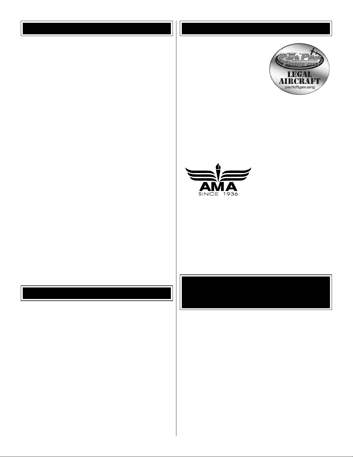
TABLE OF CONTENTS
AMA
INTRODUCTION . . . . . . . . . . . . . . . . . . . . . . . . . . . . . . . .2
AMA . . . . . . . . . . . . . . . . . . . . . . . . . . . . . . . . . . . . . . . . . .2
SAFETY PRECAUTIONS . . . . . . . . . . . . . . . . . . . . . . . . .2
ADDITIONAL ITEMS REQUIRED . . . . . . . . . . . . . . . . . . .3
Spare Prop-Saver O-Rings . . . . . . . . . . . . . . . . . . . . .3
Motor, ESC and Radio Gear . . . . . . . . . . . . . . . . . . . .3
Batteries and Charging Equipment . . . . . . . . . . . . . . .3
Assembly Tools . . . . . . . . . . . . . . . . . . . . . . . . . . . . . .4
Glue For Repairs . . . . . . . . . . . . . . . . . . . . . . . . . . . . .4
ORDERING REPLACEMENT PARTS . . . . . . . . . . . . . . . . 5
KIT INSPECTION. . . . . . . . . . . . . . . . . . . . . . . . . . . . . . . . 5
ASSEMBLY . . . . . . . . . . . . . . . . . . . . . . . . . . . . . . . . . . . .6
Prepare the Fuselage . . . . . . . . . . . . . . . . . . . . . . . . .6
Mount the Motor. . . . . . . . . . . . . . . . . . . . . . . . . . . . . .6
Mount the Servos. . . . . . . . . . . . . . . . . . . . . . . . . . . . .9
Mount the Horizontal and Vertical Stabilizer . . . . . . .10
FINAL CONTROL SET UP . . . . . . . . . . . . . . . . . . . . . . .13
Center the Control Surfaces. . . . . . . . . . . . . . . . . . . .13
Check the Control Direction . . . . . . . . . . . . . . . . . . . .13
Check the Control Throws . . . . . . . . . . . . . . . . . . . . . 14
GET THE MODEL READY TO FLY . . . . . . . . . . . . . . . . .15
Prepare the Wing . . . . . . . . . . . . . . . . . . . . . . . . . . . .15
Balance the Model (C.G.). . . . . . . . . . . . . . . . . . . . . .16
PREFLIGHT . . . . . . . . . . . . . . . . . . . . . . . . . . . . . . . . . . .18
FLYING. . . . . . . . . . . . . . . . . . . . . . . . . . . . . . . . . . . . . . . 19
Find a Suitable Flying Site . . . . . . . . . . . . . . . . . . . . .19
Get Ready to Fly . . . . . . . . . . . . . . . . . . . . . . . . . . . .19
Takeoff . . . . . . . . . . . . . . . . . . . . . . . . . . . . . . . . . . . .19
Flying . . . . . . . . . . . . . . . . . . . . . . . . . . . . . . . . . . . . .20
Landing . . . . . . . . . . . . . . . . . . . . . . . . . . . . . . . . . . .22
If you are not already a member
of the AMA, please join! The AMA
is the governing body of model
aviation and membership provides
liability insurance coverage,
protects modelers’ rights and
interests and is required to fl y at
most R/C sites. The AMA has two
classes of membership available;
open membership or their Park Pilot Program, which this
aircraft qualifi es for. The Park Pilot Program is for people
fl ying electric aircraft and gliders under two pounds and
which fl y slower than 60mph. This will enable you to enjoy
most AMA benefi ts and organize clubs and fl ying sites in
more congested areas.
ACADEMY OF MODEL AERONAUTICS
5151 East Memorial Drive
Muncie, IN 47302-9252
Tele. (800) 435-9262
Fax (765) 741-0057
Or via the Internet at:
http://www.modelaircraft.org
http://www.modelaircraft.org/parkfl yer.aspx
IMPORTANT!!!
Two of the most important things you can do to preserve the
radio controlled aircraft hobby are to avoid fl ying near fullscale aircraft and avoid fl ying near or over groups of people.
®
INTRODUCTION
Thank you for purchasing the Great Planes ElectriFly FlyLite
ARF. The original concept for the FlyLite was to develop a
slow-fl ying indoor trainer for beginners or pilots with little R/C
experience. This goal was achieved, but then we found out
how much fun it was to fl y the FlyLite outdoors too! Outdoors
in calm conditions, beginners will have all the space they need
to detect what the FlyLite is doing, process the information,
then make the necessary control inputs. Experienced pilots
will fi nd ways to challenge themselves by fl ying low, high,
close, far and fi guring out what aerobatic tricks they can get
the FlyLite to do. And if thermals are present the FlyLite can
easily achieve twenty-minute (or longer) fl ights!
For the latest technical updates or manual corrections to the
FlyLite visit the Great Planes web site at www.greatplanes.
com. Open the “Airplanes” link, then select “FlyLite ARF”. If
there is new technical information or changes to this model
a “tech notice” box will appear in the upper left corner of
the page.
PROTECT YOUR MODEL, YOURSELF
& OTHERS… FOLLOW THESE
IMPORTANT SAFETY PRECAUTIONS
1. Your FlyLite should not be considered a toy, but rather a
sophisticated, working model that functions very much like
a full-size airplane. Because of its performance capabilities,
the FlyLite, if not assembled and operated correctly, could
possibly cause injury to yourself or spectators and damage
to property.
2. You must assemble the model according to the instructions.
Do not alter or modify the model, as doing so may result in
an unsafe or unfl yable model. In a few cases the instructions
may differ slightly from the photos. In those instances the
written instructions should be considered as correct.
3. You must use an R/C radio system that is in good condition,
a correctly sized motor, and other components as specifi ed
in this instruction manual. All components must be correctly
installed so that the model operates correctly on the ground
and in the air. You must check the operation of the model and
all components before every fl ight.
2
Page 3
4. If you are not an experienced pilot or have not fl own
this type of model before, we recommend that you get the
assistance of an experienced pilot in your R/C club for
your fi rst fl ights. If you’re not a member of a club, your local
hobby shop has information about clubs in your area whose
membership includes experienced pilots.
5. While the FlyLite has been fl ight tested to exceed normal use,
if it will be used for high-stress fl ying the modeler is responsible
for taking steps to reinforce the plane as necessary.
We, as the kit manufacturer, provide you with a top quality,
thoroughly tested kit and instructions, but ultimately the
quality and fl yability of your fi nished model depends
on how you build it; therefore, we cannot in any way
guarantee the performance of your completed model,
and no representations are expressed or implied as to the
performance or safety of your completed model.
ADDITIONAL ITEMS REQUIRED
Spare Prop-Saver O-Rings
The included Great Planes 8
x 6 Power Flow™ Slow-Flyer
propeller is secured to the motor
with a rubber O-ring. In a crash,
the O-ring prevents damage by
allowing the propeller to fl ex on
the motor shaft (see page 16).
The RimFire 250 motor includes
two O-rings, but you should have
spares in case one becomes
damaged or lost, so be certain to purchase a package of
spare O-rings soon (GPMG1405).
Motor, ESC and Radio Gear
This is a list of motor-related items and radio gear required to
fi nish the FlyLite. Order numbers are provided in parentheses.
• Great Planes ElectriFly RimFire 250 electric motor
(GPMG4502)
• Great Planes Silver Series SS-8 8A brushless electronic
speed control (ESC) (GPMM1800)
• The balsa servo tray in the FlyLite is fi tted for Great Planes
ES40 Pico servos (GPMM1200). Other micro servos (such
as the Futaba® S3114, FUTM0414) are also suitable, but
the servo tray may require slight trimming to fi t them.
• Any small 3- or 4-channel receiver is suitable for the FlyLite.
Futaba R607FS and R617FS 2.4GHz receivers work
perfectly well, but for the lightest weight and best performance
the Futaba R6004FF receiver (FUTL7624) is recommended.
Note: Although the FlyLite has been fl own at great distances
outdoors with the R6004FF receiver, technically, this is an
“indoor” receiver, so if you plan to fl y your FlyLite far away or
maybe even catch thermals, a regular receiver such as the
R607FS or R617FS may be more suitable.
• If you do not already have a transmitter, the Futaba 6EX
6-channel 2.4GHz radio system (FUTK6900) is a suitable
option. This system includes the R617FS receiver, so if
the smaller R6004FF receiver is preferred it will have to be
purchased separately. The 6EX has six-model memory, so
even if it seems as though this system is more complicated
than necessary, up to six different models can be fl own with
this transmitter without having to reprogram as you evolve
in the hobby and accumulate more models. Additionally,
the R617FS receiver is perfect for other larger planes that
you will grow into.
Batteries and Charging Equipment
• The FlyLite requires one Great Planes 7.4V 300mAh BP
LiPo (Lithium Polymer) battery (GPMP0700). This battery
powers the motor, receiver and servos. But when the battery
drops below a certain voltage the ESC cuts power to the
motor, leaving reserve power for the servos and receiver so
you can maintain control for a landing. Although only one
battery is needed, most pilots bring at least three or four
charged batteries to the fl ying fi eld so they do not have to
wait for charging between fl ights.
Indoors or in absolutely calm conditions outdoors (where low
throttle settings are used), the FlyLite may fl y for as long as
fi fteen minutes. However, in breezy conditions higher throttle
settings are typically used, shortening average fl ying times
to around fi ve minutes.
• A LiPo-capable battery charger and a power source for
the battery charger is required. Virtually all suitable battery
chargers can be powered by a 12V battery, but it is more
convenient to use a charger that can be connected either
to a 12V battery (for charging at the fl ying fi eld) or to a
110V wall outlet (for charging at home). One suitable LiPo
charger is the Great Planes ElectriFly Triton™ EQ AC/DC
Charger (GPMM3155). And in addition to its LiPo capability,
the Triton EQ also features one more critical component
which is a built-in LiPo cell balancer. For the best LiPo
performance, longevity and safety, a LiPo cell balancer
must be used so each individual cell in the LiPo battery can
be charged evenly.
• Another suitable LiPo battery charger is the Great Planes
PolyCharge4™ DC LiPo charger (GPMM3015). The
advantage of the PolyCharge4 is that it can charge up to
four LiPo batteries at the same time. But unlike the Triton
EQ, the PolyCharge4 does not have an internal LiPo cell
balancer, so for each LiPo battery you wish to charge
simultaneously (up to 4), one Great Planes Equinox
LiPo Cell Balancer (GPMM3160) will be required. Finally,
the PolyCharge4 does not have AC capability, so if wallcharging from home is a priority a separate A/C 12-Volt
power source must be purchased separately. A suitable
power supply then for the PolyCharge4 is the Great Planes
12V 12A DC power supply (GPMP0901).
3
™
Page 4
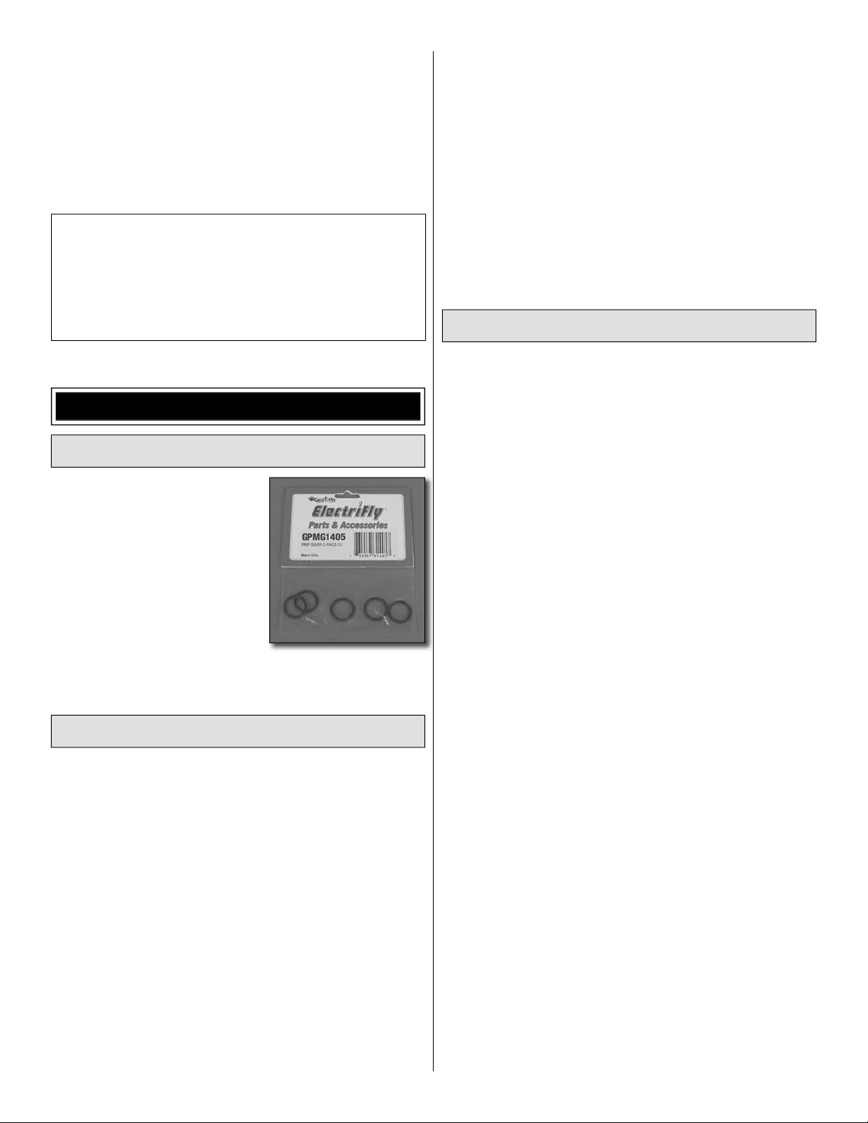
Assembly Tools
Few tools are required to assemble your FlyLite, so if you
have these on-hand before you begin you’ll be in the air in
no time.
Small needle-nose pliers (HCAR0625) or hemostats
❏
(BRUR1302)
#0 magnetized (if possible) Phillips screwdriver
❏
(DTXR0170) (A screwdriver can be magnetized by
rubbing a magnet against it.)
Hobby knife (EXLR6018) with #11 blade (XACR3121)
❏
Segmented lead weights (GPMQ4485) for beginners and
❏
outdoor fl ying (see page 18).
Glue for Repairs
If repairs to your FlyLite are ever required, note that there are
certain types of glues that should be used. Usually, foam-
safe CA (super glue) is required to repair foam models and
many modelers keep some in their fl ight box so they can
make repairs at the fi eld. While only foam-safe CA can be
used on the wing, tail surfaces and on the battery plate in
the fuselage, the fuselage may be glued with either regular
CA or foam-safe CA. Sometimes though, you accidentally
reach for the wrong bottle on your workbench or forget which
kind of CA can be used on which parts, so it’s easiest just
to forget about regular CA and use only foam-safe CA when
making repairs to any part of the model. And when making
repairs, simply gluing the parts back together with CA alone
usually doesn’t work. Without a catalyst, CA can take a long
time to harden. To speed drying time, apply CA, hold the
parts together, and then have an assistant apply a light mist
of CA accelerator causing the CA to harden within seconds.
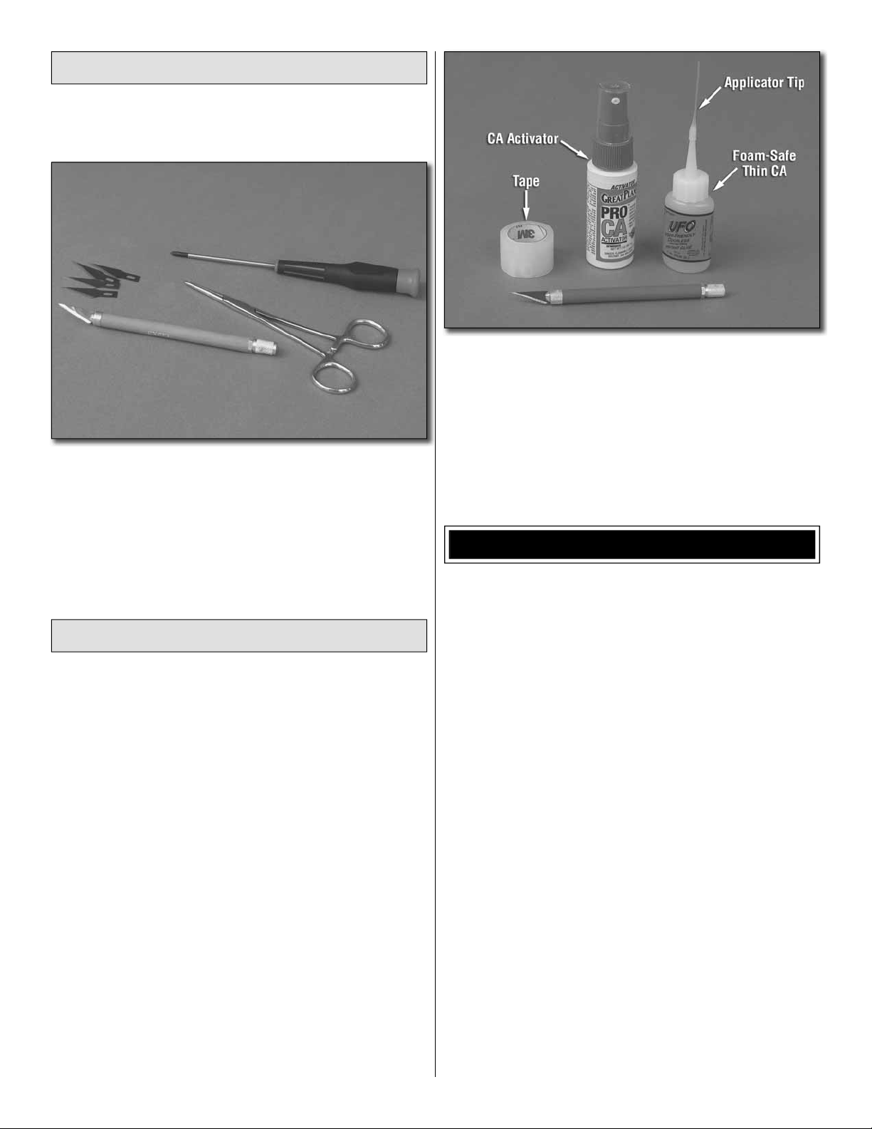
If you want to assemble a repair kit, following are some
recommended items:
UFO Thin foam-safe CA (HOTR1040)
Great Planes Pro™ CA activator (GPMR6035)
Hobbico® CA applicator tips (HCAR3780)
Du Bro® electric fl yer hinge tape (DUBQ0916)
#1 knife blade knife (EXLR6018)
#11 hobby blades (XACR3121)
ORDERING REPLACEMENT PARTS
Replacement parts for the FlyLite are available using the
order numbers in the Replacement Parts List that follows.
The fastest, most economical service can be provided by
your hobby dealer or mail-order company.
To locate a hobby dealer, visit the Great Planes web site
at www.greatplanes.com. Choose “Where to Buy” at the
bottom of the menu on the left side of the page. Follow the
instructions provided on the page to locate a U.S., Canadian
or International dealer.
Parts may also be ordered directly from Hobby Services
by calling (217) 398-0007, or fax at (217) 398-7721, but full
retail prices and shipping and handling charges will apply.
Illinois and Nevada residents will also be charged sales tax.
If ordering via fax, include a Visa® or MasterCard® number
and expiration date for payment.
Mail parts orders and payments by personal check to:
Hobby Services
3002 N. Apollo Drive, Suite 1
Champaign, IL 61822
Be certain to specify the order number exactly as listed in
the Replacement Parts List. Payment by credit card or
personal check only; no C.O.D.
If additional assistance is required for any reason, contact
Product Support by telephone at (217) 398-8970, or by
e-mail at productsupport@greatplanes.com.
4
Page 5
REPLACEMENT PARTS LIST
Order No. Description
GPMA2581
GPMA2582
GPMA2583
GPMA2584
GPMA2585
GPMA2586
GPMA2587
GPMA6610
NOTE
Wing
Fuselage Set
Tail Surface Set
Landing Gear Set
Battery Hatch
Faslink Pushrod Connector (6)
Wing Mounting Rubber Bands (6)
8x6 Power Flow Propeller (2)
Full-size plans are not available.
You can download a copy of this
manual at www.greatplanes.com.
KIT INSPECTION
Before starting to build, inspect the parts to make sure they
are of acceptable quality. If any parts are missing or are not of
acceptable quality, or if you need assistance with assembly,
contact Product Support. When reporting defective or
missing parts, use the part names exactly as they are written
in the Kit Contents list.
Great Planes Product Support
3002 N. Apollo Drive, Suite 1
Champaign, IL 61822
Telephone: (217) 398-8970, ext. 5
Fax: (217) 398-7721
E-mail: airsupport@greatplanes.com
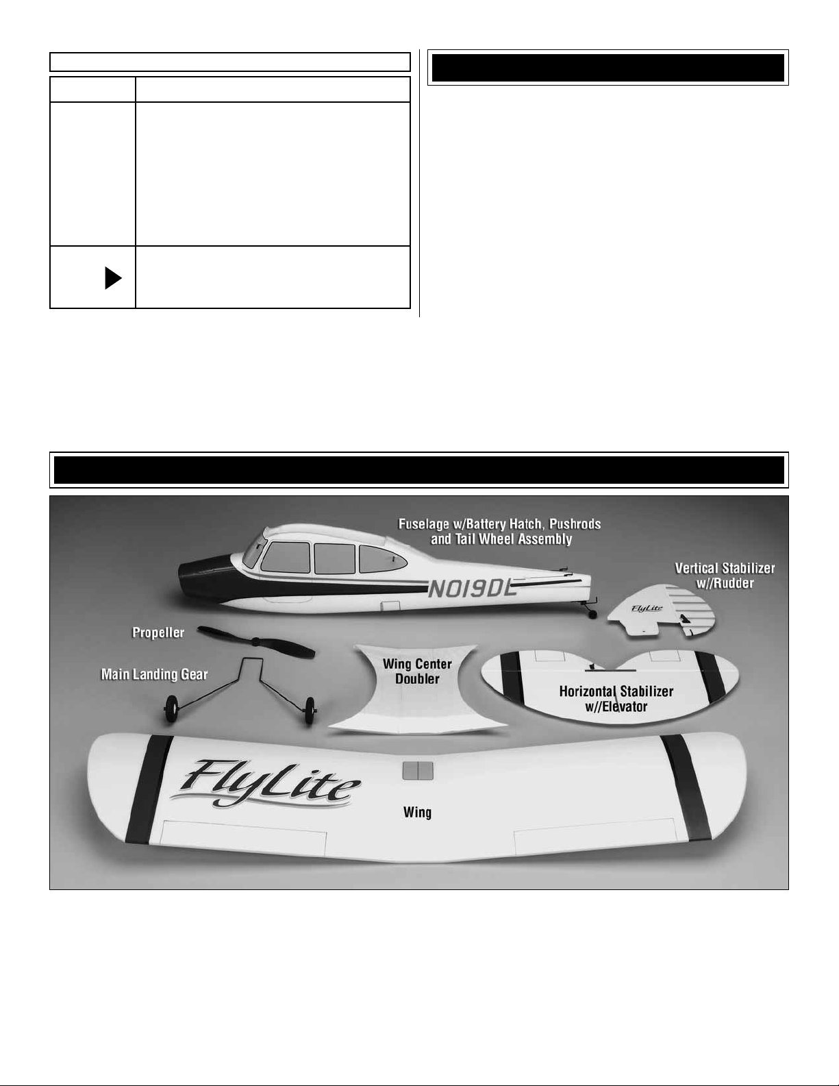
KIT CONTENTS
5
Page 6
ASSEMBLY
Prepare the Fuselage
Your transmitter and a charged battery will be required
soon for setting up the radio. If you plan to fl y your FlyLite
immediately, charge your battery now so you will not have
to wait later.
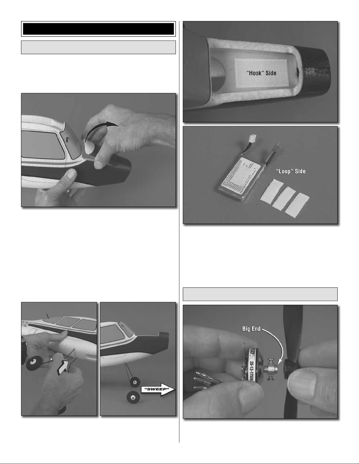
1. Lift the back of the battery hatch to remove it from the
❏
fuselage—a little more force than usual may be required for
the fi rst time as there may be some residual glue sticking the
parts together. Use care.
2. There may be a small piece of tape temporarily stuck
❏
to the magnet on the hatch or to the magnet in the fuselage.
Remove the tape and throw it away. Set the hatch aside.
4. Apply the rougher, “hook” side of the included Velcro
❏
hook-and-loop strip to the battery mounting plate in the
fuselage. Cut the softer, “loop” side of the Velcro strip into
four pieces and attach one of the strips to your battery. If you
already have more batteries you can apply the other strips to
the batteries now. If you ever need more Velcro later, it can
also be purchased separately (GPMQ4480).
Mount the Motor
3. Lightly squeeze the main landing gear wire together
❏
and fi t it all the way up into the fuselage with the bent-in
“sweep” in the wire facing forward.
1. Test fi t the included 8 x 6 Slow Flyer propeller onto the
❏
prop-saver propeller adapter on the RimFire 250 motor. If the
propeller fi ts loosely, use a #0 or #1 Phillips screwdriver to
6
Page 7
remove the adapter. Flip it over so the big end is forward, and
then reattach the adapter to the propeller shaft. Make certain
the screws settle onto the fl at spots on the motor shaft and
tighten them securely.
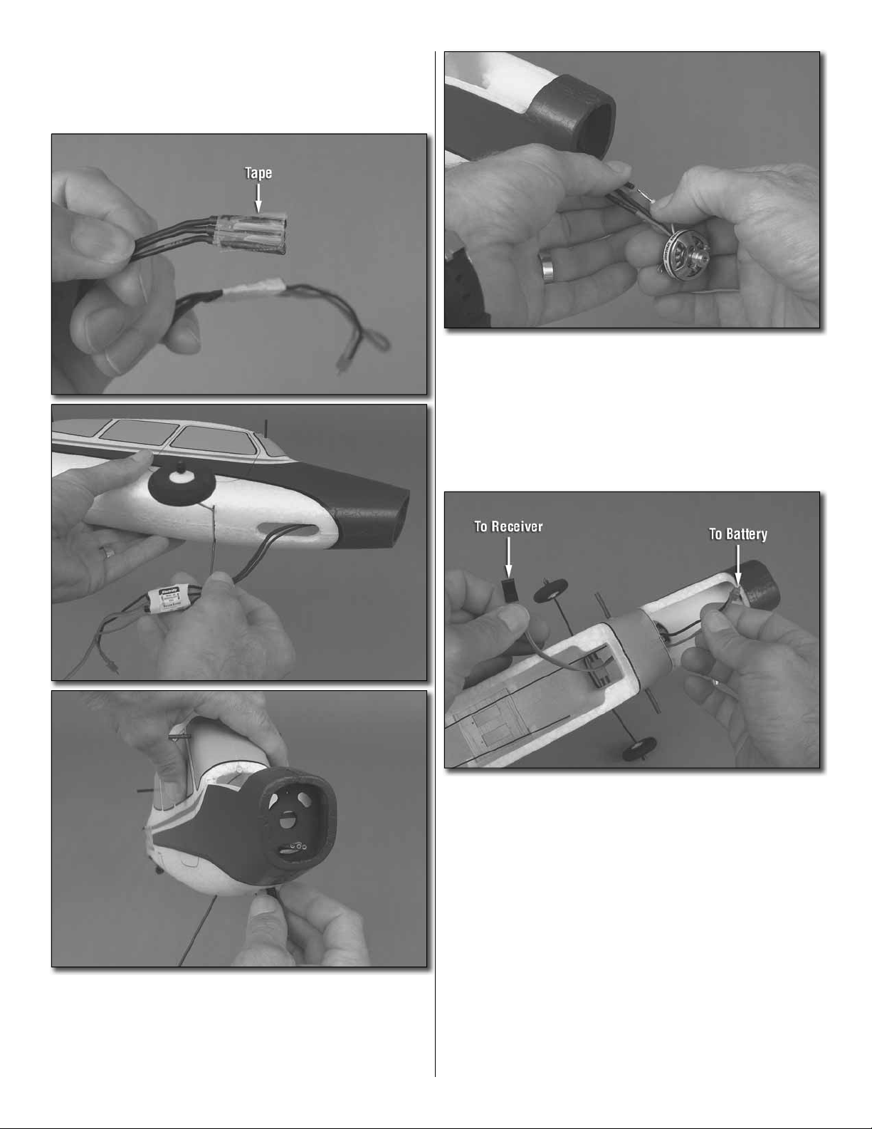
3. Remove the tape from the ESC wires and connect the
❏
motor to the ESC. It doesn’t matter which way the wires go
for now because it’s just a guess anyway—we’ll make sure
the wires are properly connected later.
2. Temporarily tape together the end of the three motor
❏
wires from the ESC (electronic speed control). Feed the wires
up through the hole in the bottom of the fuselage and out
the hole in the bottom of the fi rewall–this may require a little
fi nagling by holding the fuselage vertically or using a toothpick
or something similar to coax the wires out through the hole.
4. Place the ESC in the fuselage by guiding it up into the
❏
hole in the bottom. From the top of the fuselage, pull the ESC
wire that goes to the receiver up and over the landing gear
mount into the radio compartment and pull the battery wire
into the battery compartment.
7
Page 8
Advance Throttle Stick
Motor runs full speed
Lower Throttle Stick
Motor turns off
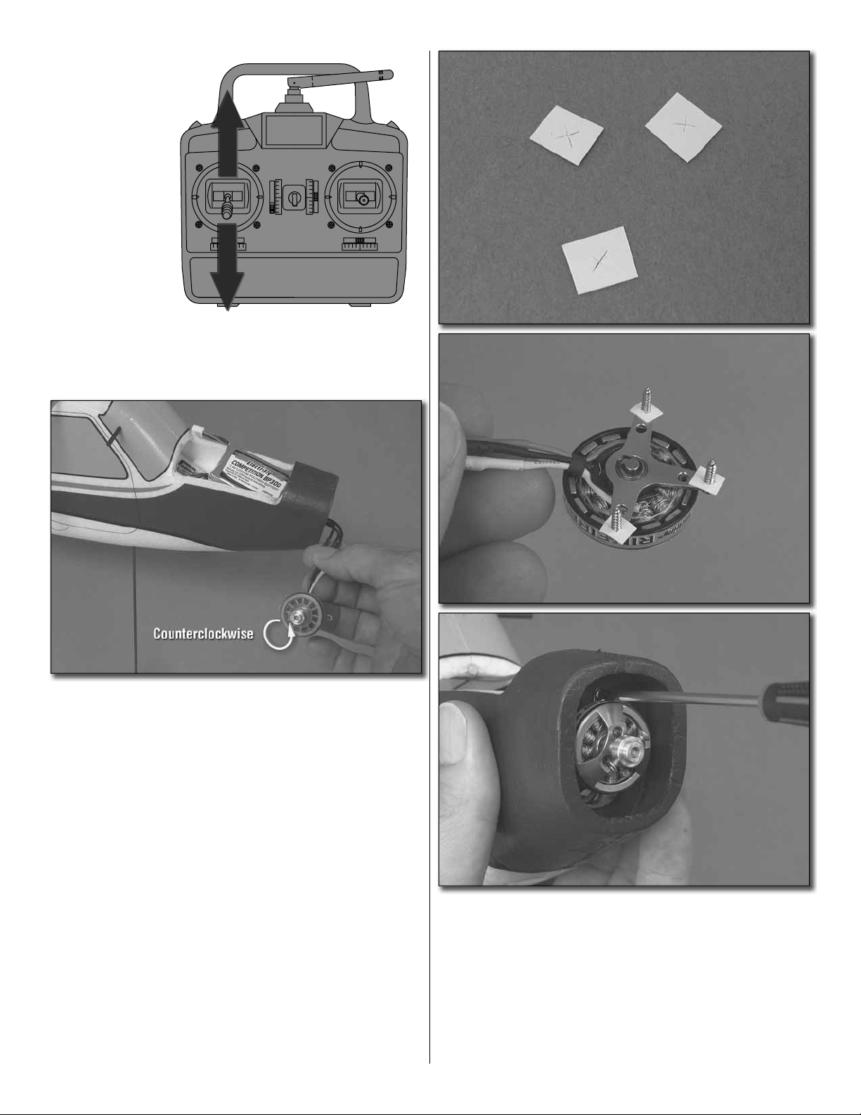
5. If using the ElectriFly SS-8 ESC and a Futaba radio,
❏
set the throttle channel in your transmitter to “reverse” so the
motor will turn when you advance the throttle.
6. Connect the ESC to channel 3 in your receiver. Turn
❏
on your transmitter. Connect the battery to the battery wire
coming from the ESC. Holding the motor in your hand,
advance the throttle stick on your transmitter to see if the
motor is turning in the correct direction—it should be turning
counter-clockwise if viewing the motor from the front. If the
motor is not turning the correct direction, swap any two
motor/ESC wires with each other. Confi rm that the motor is
now turning in the correct direction by advancing the throttle
stick again.
7. If your #0 Phillips screwdriver is not magnetic, rub a
❏
magnet against it several times to get it magnetized.
8. Hold the motor to the fi rewall, aligning the screw holes
❏
in the motor with the holes in the fi rewall. Mount the motor
with three 2mm x 8mm Phillips screws included with this
kit (six screws are included, but three are for spares). You
should be able to pick up the screws with your magnetic
screwdriver and just screw them in. If your screwdriver is
not magnetic, make small washers from thin cardstock or
construction paper to hold the screws to the motor, and then
mount the motor. DO NOT mount the propeller to the motor
at this time.
8
Page 9

Mount the Servos
It’s okay to cut out this
part to make it easier
to fit larger servos.
Servo Tray
1. If not using the recommended ES40 Pico servos, test fi t
❏
the servos you will be using in the servo tray in the fuselage.
If your servos don’t fi t, use a hobby knife to carefully trim the
tray as necessary—if it makes the trimming job easier you
can cut out the center part of the tray.
Use this photo for the next two steps:
ES40 Pico Servos
Cut off
3/8" [9.5mm]
“Other” Servo Arm
2. If you are using the recommended ElectriFly ES40 Pico
❏
servos, prepare the servo arms that came with the servos by
cutting them as illustrated. If not using Pico servos, prepare
two servo arms so the pushrod mounting holes will be 3/8"
[9.5mm] from the arm mounting screw.
Trim the corners
Make two
4. Connect the rudder and elevator servos to the
❏
receiver—the servo on the right is the rudder servo and goes
to channel 1 in the receiver and the servo on the left is the
elevator servo and goes to channel 2 in the receiver.
90°
99°
Perfect
90°
95°
Acceptable
Close enough to 90°
90°
95°
99°
Not Good
Too far from 90°
5. Turn on your transmitter and make sure the trims are
❏
centered. Connect the battery to the ESC. This will “center”
the servos. Fit the servo arms onto the servos so they will be
as close as you can get them to 90° to the pushrods—it may
not be possible to get the servo arms precisely 90°, so just
get them as close as you can. This will provide symmetrical
control surface throw (discussed on page 14).
3. Mount a screw-lock connector to each servo arm using
❏
the small, black nylon retainer—if the screw-lock connectors
don’t fi t in the servo arm holes use a #55 drill or a hobby
knife to carefully enlarge the holes just enough to fi t the
micro screw-lock connector. Thread a 2mm x 4mm Phillips
machine screw into each screw-lock connector.
NO
Pressed all the way down
6. Make sure the servo arms are fi rmly pressed all the
❏
way down onto the splined shafts and install the screws that
hold on the arms.
9
YES
Page 10

7. Unplug the elevator servo from the receiver. Guide
❏
the elevator servo wire down through the servo tray and
reconnect the servo wire to the receiver. Do the same with
the rudder servo, and then just let the servos hang by the
wires over the side of the fuselage for now.
use the longer wood screws that came with the ES40 Pico
servos)—use care not to over tighten the screws because it
is easy to strip out the balsa. If you do strip out the balsa the
glue you added will hold the screws. Hint: If the servo arm is
in the way of one of the screws, turn on your radio and use
the transmitter to rotate the servo arm to accommodate your
screwdriver.
10. Install the receiver in the fuselage. If preferred, the
❏
receiver could be mounted to the inside of the fuselage using
the included double-sided foam mounting tape. But on an
electric-powered model this small, it’s okay to just drop the
receiver down in there without mounting it to anything. The
same applies to the ESC. NOTE: If you’re using a 72mHz
receiver that has a long antenna, you can guide the antenna
out the hole in the bottom of the fuselage and tape the end
under the tail.
Mount the Horizontal and
Vertical Stabilizers
8. Add a drop of glue to the four screw holes in the servo tray
❏
(or, simply glue the servos into postition)—just about any kind
of glue is suitable as long as it will stick to wood. This will help
the servo mounting screws stay secure in the balsa. Proceed
immediately to the next step before the glue hardens.
90° Pushrod connector
1. Remove the 90° pushrod connectors from the pushrods
❏
in the fuselage and set the connectors aside.
Rudder horn
Middle hole
Elevator horn
Outer hole
9. Fit the servos in the tray and carefully screw them down
❏
with the included 1.6mm x 4mm Phillips screws (or you may
2. Slide one of the pushrods out of the fuselage and test
❏
fi t it into the middle hole in the rudder control horn and into
10
Page 11

the outer hole in the elevator control horn. If necessary, use
a hobby knife to carefully enlarge the holes in the horns just
until the pushrods will go in.
3. Carefully fl ex the elevator and rudder back and forth a
❏
few times to about a 45° angle to loosen the hinge line.
4. Fit the elevator pushrod into the outer hole in the
❏
elevator horn and snap a 90° pushrod connector over the
wire so it won’t come off. (The connectors can also be
installed/removed after the plane is together, but it’s easier
to do it now.)
5. Guide the pushrod wire up through the pushrod tube in
❏
the fuselage as you slide the horizontal stabilizer (stab) into
position. Insert the wire into the screw-lock connector on the
elevator servo and slide the stab the rest of the way in.
Center the slot in
the stab with the
slot in the fuselage.
6. Center the slot in the stab with the slot in the fuselage
❏
for the vertical stabilizer (fi n).
11
Page 12

7. Same as was done with the stab, connect the rudder
❏
pushrod to the middle hole in the rudder horn and install the
90-degree pushrod connector. Fit the rudder pushrod and
fi n into position holding the fuselage by the bottom under
the stab and holding the fi n at its base as shown. Carefully
work the fi n into position until it is almost, but not quite, all
the way in.
This is what the rudder/pushrod/tail wheel assembly looks
like when properly installed.
9. View the bottom of the FlyLite looking at the alignment
❏
between the rudder and the tail wheel—the two should be
centered (or very nearly centered) with each other so the
plane will roll straight. If necessary, use the included hex key
wrench to loosen the set screw in the collar. Center the tail
wheel with the rudder, and then tighten the screw. Use care
to tighten the screw just enough to lock the tail wire into
place. Otherwise, you may strip out the plastic.
❏ 8. Fit the tail gear wire into the tube in the bottom of the
rudder, then install the fi n the rest of the way into the fuselage
until it is snug and secure. Note: The fi n is held into position
with built-in magnets (which also lock in the stab), so no glue
is required.
12
Page 13

FINAL CONTROL SET UP
Your FlyLite is nearly complete, but fi rst there a few lastminute procedures.
Center the Control Surfaces
Centered/Neutral
Down Trim
[4.8mm]
3/16"
INDOOR SETUP
OUTDOOR SETUP
Centered/Neutral
2. Same as was done in the previous step for the elevator,
❏
center the rudder and tighten the screw in the screw-lock
connector to lock the pushrod down.
Check the Control Direction
Move control stick right
Rudder moves right
1. Turn on your transmitter and connect the battery to the
❏
ESC in the plane. Being certain the trims on your transmitter
are still centered, center the elevator. Then use needle-nose
pliers or hemostats to hold the screw-lock connector while
tightening the screw to lock the pushrod down. Note: If
fl ying your FlyLite outdoors, rather than having the elevator
centered, it should have approximately 3/16" [5mm] of down
trim. This will allow your FlyLite to fl y level when fl ying at
faster speeds typically used outdoors.
Pull control stick back
Elevator moves up
Operate the controls on the transmitter to make certain
❏
the elevator and rudder respond in the correct direction. If
necessary, reverse the servo reversing in your transmitter to
get the controls to respond the right way.
13
Page 14

CONTROL
THROW
Check the Control Throws
Up
Down
One of the most important factors in determining how a plane
fl ies—and your ability to control it—is the control throw, or how
far each control surface moves up and down or left and right.
If the throw is too much the plane will respond too quickly and
you will end up over controlling it. If the throw is too little the
plane will respond too slowly and there may not be enough to
maneuver or change direction. Follow the procedure below to
make sure the control throws are set properly.
Measure the elevator throw fi rst:
1. Use a small box or something similar to prop up the aft
❏
end of the fuselage so the stab will be level (or nearly level).
3. Use your transmitter to move the elevator up and
❏
measure the distance it moved from center. This is your “up”
control throw. Measure the down elevator control throw the
same way.
Compare the measured up and down elevator throw to the
recommended control throws below:
These are the recommended control surface throws:
HIGH RATE LOW RATE
Up
ELEVATOR
RUDDER
4. As long as your elevator throw is within 1/8" [3.2mm]
❏
of the recommended throws above, your elevator throw is
acceptable. If your elevator throw is not within 1/8" [3.2mm],
use the end point adjustments in your transmitter (if yours
has this feature) to tune the throw. If your radio does not have
end point adjustments, change the location of the pushrod in
the elevator horn or in the servo arm as illustrated below:
3/4"
[19mm]
21°
Right
1-1/4"
[32mm]
29°
Down
3/4"
[19mm]
21°
Left
1-1/4"
[32mm]
29°
Up
1/2"
[13mm]
14°
Right
3/4"
[19mm]
17°
Down
1/2"
[13mm]
14°
Left
3/4"
[19mm]
17°
2. Still without the propeller mounted to the motor,
❏
turn on your transmitter and connect the battery. Place a
ruler to the trailing edge of the elevator at the widest part
(from front-to-back).
14
Page 15

Move the pushrod out on
the control surface to
reduce control throw.
Less throw
On the servo end, move the
pushrod out to increase throw
or in to decrease throw.
More throw
Move the pushrod in on
the control surface to
increase control throw.
More throw
Less throw
Optional: Add the Wing Center Doubler. If fl ying the
FlyLite outdoors, or if fl ying more aggressively in large
indoor sites where higher throttle settings may be used
more often, do not use the rubber band protectors. Instead,
the formed wing center doubler and fi ber-reinforced tape
must be added to the wing as they increase strength.
The center doubler is adhered to the top of the wing with
aggressive double-sided adhesive tape, so once installed
it is permanent. Follow these instructions to apply the
center wing doubler and fi ber-reinforced tape.
5. Check and if necessary, adjust the rudder throw the
❏
same way so it is within 1/8" [3.2mm] of the specifi ed throw.
GET THE MODEL READY TO FLY
Prepare the Wing
1. If fl ying the FlyLite indoors, remove the protective
❏
backing from the adhesive on the rubber band protectors
and apply them to the top of the wing centered over the
leading and trailing edges. Proceed to “Balance the Model
(C.G.)” on the next page.
2. Before removing the protective backing over the double-
❏
sided tape on the bottom of the center doubler, test fi t it onto
the wing. Use a fi ne-point felt-tip pen to mark the center of
the doubler and the wing at the trailing edge. This will be a
reference mark for aligning the doubler in the next step.
3. Peel off the protective covering from the tape on the
❏
back of the center doubler. Then join only the back edge
of the doubler to the top of the wing by holding them upside
down and aligning the marks.
15
Page 16

4. Keeping the rest of the center doubler from contacting
❏
the wing by holding the two apart, fl ip the assembly over.
Then starting at the back and working forward, press the
doubler all the way into position.
5. Supporting the bottom of the wing under the doubler,
❏
make certain the doubler is securely bonded to the top of the
wing by carefully but thoroughly pressing it down.
Balance the Model (C.G.)
Another critical factor in determining how a plane fl ies
(and again your ability to control it) is the center of gravity
(C.G.), or the balance point. If the balance point is too
far aft the plane will be unstable and react too quickly to
your control inputs. If the balance point is too far forward
the plane will be too stable and not react enough to your
control inputs. Beginners should never fl y the FlyLite if it
is balanced outside of the balance range specifi ed on the
next page.
6. If necessary, use a single-edge razor blade or a hobby
❏
knife to trim a thin fi lm of material (1/32" [.8mm]) from where
the trailing edge of the wing contacts the fuselage. This
will allow the wing to fi t properly with the center doubler
installed.
The fi ber-reinforced tape must also be added to the
bottom of the wing, but this will be done after marking
the C.G. lines in following steps.
1. To balance the model, all components must be installed
❏
including the propeller. Mount the propeller to the motor using
the rubber prop-saver O-ring that came with the motor. The
best way is to hook the O-ring around one of the screws, and
then fi t the propeller and use a small Phillips screwdriver or
something similar to hook the other end of the O-ring up and
around the other screw.
16
Page 17

BOTTOM OF WING
Align with wing leading edge Align with wing leading edge
2-1/8" [54mm] from wing leading edge
BALANCE RANGE
2-7/8" [73mm] from wing leading edge
2. Cut the C.G. Marking Guide from the back of the
❏
2-1/8" [54mm] from wing leading edge
BALANCE RANGE
2-7/8" [73mm] from wing leading edge
manual along the dashed lines. Then fold the guide along
the solid line at the front where shown. Place the guide on
the bottom of one half of the wing next to the bend over the
fuselage. Align the front of the template with the leading edge
of the wing. Use a fi ne-point ballpoint pen or a pin to poke
small dimples through the four cross marks into the wing.
Note: The C.G. range is 2-1/8" [54mm] to 2-7/8" [73mm]
from the leading edge of the wing and can also be marked
with a ruler if the templates get misplaced.
5. If you still need to add the fi ber-reinforced tape to the
❏
bottom of the wing for outdoor fl ying or aggressive indoor
fl ying, cut a 24" [610mm] strip of the included fi ber-reinforced
tape and add it to the bottom of the wing centered between
the lines marked in the previous step. If not adding the fi berreinforced tape, instead apply narrow strips of pin striping
tape or masking tape over the lines so you will be able to feel
them with your fi ngers when balancing the plane later. Note:
If you are an experienced pilot and will be intentionally
abusing your FlyLite by fl ying it as aggressively as you can,
cut the remaining piece of reinforced tape in half. Apply these
strips to the bottom of the wing 1" [25mm] ahead of and 1"
[25mm] behind the fi rst strip.
Now your FlyLite should be ready-to-fl y with everything
in place including the servos, pushrods, receiver, ESC
and propeller.
3. Move the marking guide to the other half of the wing
❏
and make another set of marks.
4. Use a straightedge and a fi ne-point felt-tip pen to draw
❏
the C.G. range lines on the bottom of the wing connecting
the sets of marks.
6. Install the battery (no need to connect it to the ESC) and
❏
the battery hatch. Mount the wing with two rubber bands.
17
Page 18

7. Lift the plane with one fi nger of each hand between the
❏
C.G. range lines on both sides of the wing—you should be
able to feel the forward and aft limits because of the tape.
Position your fi ngers between the lines as necessary to get
the plane to sit level. As long as you can get the plane level
with your fi ngers anywhere between the lines, the FlyLite
is balanced within the recommended range. Note that the
farther back the FlyLite balances the more maneuverable
it will be and the slower you should be able to get it to fl y.
But this may be too maneuverable for beginners. The farther
forward your FlyLite balances, the more stable it will be
which is better for beginners and fl ying outdoors. Note that
a forward C.G. (nose weight) is strongly recommended for
beginners. If you want to change the balance point perform
the following steps.
9. Attach the lead where required—in the nose, segments
❏
can be attached to the back of the fi rewall or to the hatch. If
using tail weight, it can be attached to the side of the fuselage
under the stab.
If you added any weight, double-check the balance point to
make sure it is still within the specifi ed range.
PREFLIGHT
1. It is a good idea to write your name, address and
❏
telephone number on or in the model. This can be done with
a fi ne-point felt-tip pen. If you fl y your FlyLite at an AMA R/C
club fl ying site this is required.
8. To shift the balance point forward, nose weight will
❏
be required. To shift the balance point aft tail weight will
be required. Add segments of Great Planes Stick-on lead
weight (GPMQ4485) where necessary. To fi nd out how much
lead is required before attaching it to the plane, simply place
segments of weight over the nose or on the tail to see how
much is required. Typically, 1/4 oz. to 1/2 oz. [7g to 14g] may
be required on the nose while much less (if any) weight will
be required on the tail.
2. If you haven’t yet done so, charge all of your motor
❏
batteries and make sure your transmitter battery is fully
charged as well.
FINAL CHECK LIST:
A. Check to see that the controls respond in the correct
❏
direction according to your inputs from the transmitter.
B. Set the control throws according to the
❏
recommendations on page 14.
C. Check to make sure the plane balances within the
❏
recommended range.
D. Make sure the propeller is secure and that the prop-
❏
saver O-ring is in good condition.
E. Make sure the servos are securely mounted and the
❏
pushrods are connected.
18
Page 19

FLYING
Find a Suitable Flying Site
Experienced fl yers already know their capabilities and the
precautions that should be used with fl ying even the lightest,
smallest R/C models, so they will be able to identify a suitable
fl ying site. But beginners often underestimate the skill and
space required, so they should err on the side of caution
by making sure they fi nd the ideal fl ying site—especially
for the very fi rst time. The FlyLite is designed to fl y indoors
even in a regular-size gymnasium. But for beginners a large
gymnasium or a sports fi eld house would be better until you
know your and your FlyLite’s capabilities. If fl ying outdoors,
beginners should fi nd a large, open area at least the size
of a football fi eld that is clear of obstructions such as light
poles, buildings, antennas, trees, roads and people. Finding
a suitable fi rst-time fl ying site will be well worth it even if you
have to travel far out of your way.
Later, when you become a pro with your FlyLite, you should be
able to turn it within approximately 20’ [6m] diameter circles.
Finally, if fl ying outdoors beginners MUST wait for calm
weather. Experienced pilots can have a blast fl ying the
FlyLite in winds up to around 10mph, but even a light breeze
(more than 2 or 3mph) can present too many problems for
an inexperienced pilot.
Takeoff
WIND
Pilot
The FlyLite may takeoff from smooth surfaces on the ground
or be hand-launched if a suitable runway is not available.
If taking off from the ground, set the FlyLite down pointing
directly into any prevailing breeze. If hand-launching, hold
the plane by the bottom of the fuselage under the wing.
“Arm” the motor by advancing the throttle stick all the way.
Listen for the beeps coming from the motor. Then, return
the throttle stick to idle. Advance the throttle—no more than
approximately half-power is all that will be required. In fact, it
is usually not a good idea to use any more than half-throttle
for takeoff. Otherwise the FlyLite may “jump” into the air too
quickly and establish too much of a climb—this applies both
to hand-launching and taking off from the ground. If handlaunching, simply release the FlyLite or give it a gentle toss
into the air.
Get Ready to Fly
Mount the wing to the fuselage with two rubber bands.
(Experienced pilots who will be fl ying the FlyLite aggressively,
or intermediate pilots fl ying in breezy conditions, may use
four rubber bands.) Always turn on the transmitter fi rst, then
connect the battery and install the hatch. Do not arm the
motor until you are actually ready to takeoff.
Always, always, always before each and every fl ight
operate the controls on the transmitter to make sure the
control surfaces (rudder and elevator) are responding in the
correct direction.
Perform an operational ground range test as specifi ed in the
instructions that come with your radio control system.
Beginners should set the dual rates to the low-rate position
(consult the instruction manual that came with your radio
system to set up your dual rates).
YES!
20°
NO!
Too steep! Good climb angle –
approximately 20° or less
Allow the FlyLite to establish a shallow climb. Resist the urge
to angle too steeply or turn too early.
19
Page 20

Flying
Once the FlyLite is in the air think gentle. Remember, the FlyLite is primarily an indoor fl yer designed to fl y slowly and
gracefully. Make your turns wide (or as wide as your fl ying area will permit) and slow with control inputs early and gentle—the
earlier you make corrections the less drastic they will have to be. Refrain from “racing” your FlyLite around the air like a
regular sport model—most of the time it will probably be “happiest” (easiest to fl y) at approximately 1/8 or 1/4-throttle.
Once you have the FlyLite under control adjust the trims to get it to fl y straight-and-level. You should be able to fi nd equilibrium
with your FlyLite where it cruises slowly without climbing or descending.
Crossover
If you’re a beginner, it might be best to start with a crossover pattern to avoid turning the plane toward yourself and having
to look at it directly “head-on.” This is because when the plane is coming at you, you will have to move the rudder stick to
the right to make the plane to turn to your left. This seeming “control reversal” is one of the primary situations that cause
beginners to crash.
One way to avoid having to look at the model head-on is
to turn away from it while looking over your shoulder. Then,
your FlyLite will be traveling the same general direction you
are holding the transmitter.
When the FlyLIte is coming
at you, you can turn away
from the plane looking over
your shoulder.
20
Page 21

Typical “racetrack” pattern
Figure 8
Later, when you have more experience, you can fl y the standard racetrack pattern and even fl y fi gure 8’s. In both of these
patterns there will be instances when the plane is heading directly toward you.
Having the ability to fl y these different patterns and control the model in all orientations requires a little practice and
dedication–it’s almost like homework! But the rewards are that you will be able to fl y the model in more places (with less
space and more obstacles) and have better control to avoid crashes and in the end, have more fun!
21
Page 22

Landing
Always be ready to land your FlyLite at any time. After a few fl ights you will be able to predict when the motor is going to quit
(within a minute or so), but even then one can never be precisely certain when this will happen. Run time depends on many
variables such as battery condition, the type of fl ying being done and how much throttle is being used. When you notice that
motor power just doesn’t seem to be what it was before, this is usually an indication that the battery is getting low. If you
can predict when this is going to happen, you can give yourself extra time to try more than one landing pass if the fi rst one
doesn’t work out. Most of the time though, when the motor does quit unexpectedly it is no problem because the FlyLite glides
extremely well and all you have to do is glide it in for a landing.
LANDING PROCEDURE
1. Cut power on the
downwind leg.
WIND
5. Continue to apply “up” elevator as
the model slows, finally ending up
with full “up” elevator the moment
the plane has lost all flying speed at
the same time it touches down.
2. The nose should drop automatically. Allow
the plane to establish a nose-down, 180°
banked turn by applying rudder.
3. Continue the ascending
banked turn working the
elevator to maintain airspeed
and the nose-down attitude.
4. Level the wings, applying elevator as necessary
to control the descent. If necessary, apply throttle
to stretch the approach to reach the landing zone.
Or, apply throttle and go around again if the plane
is too high.
Always land into the wind if you can—sometimes this is not possible if the motor quits unexpectedly. Landing into the wind
will reduce the FlyLite’s ground speed for the slowest, softest possible touchdown. All you have to do is cut the power and
circle around to the landing zone. While the plane is descending use the elevator to control the rate of descent. In general, the
lower and slower the plane becomes the more “up” elevator you should be holding until you “run out” of elevator the moment
the plane cannot remain airborne and touches down. Of course, if the motor has quit you will have only one chance and will
have to land the plane wherever it is. But if you still have battery power and the plane is too far away, just apply throttle to fl y
it closer or even fl y past and try another landing. Eventually you will be able to land your FlyLite right at your feet!
22
Page 23

ALSO AVAILABLE FROM GREAT PLANES
®
Great Planes® PT-19 Parkfl ier EP ARF 41.5"
GPMA1149
Wingspan: 41.5 in (1055mm)
Wing Area: 270 in² (17.4dm²)
Weight: 23 – 29 oz (650 – 820g)
Wing Loading: 12.3 - 15.5 oz/ft² (38 – 47 g/dm²)
Length: 31.5 in (800mm)
The reason the PT-19 stands out is because ElectriFly put so much into it. It’s compact for easier carrying. There’s a steerable
tail wheel for smooth, superior ground handling. The all-wood airframe is strong, lightweight and already assembled. The
motor box is prebuilt, too, and magnets in the battery make the hatch and cowl easy to remove…and reattach…in seconds.
Scale details — including instrument panels and formed windscreens for the dual cockpits, a rollover pylon, and formed wire
gear and strut covers — offer noteworthy detail with minimal effort. An authentic trim scheme done in genuine MonoKote®
fi lm make it as easy to look at as it is to fl y.
Requires: • 4-channel radio w/3 micro servos
• 28-30-950 outrunner brushless motor
• 25A brushless ESC (min.)
• 11.1V, 1600mAh LiPo battery
Great Planes® Escapade™ .40-.70 GP/EP ARF
GPMA1200
Wingspan: 52.5 in (1,340 mm)
Wing Area: 483 in² (31.2 dm²)
Weight: 5.0-5.5 lb (2,270 – 2,495 g)
Wing Loading: 24 - 26 oz/ft² (73 - 80 g/dm²)
Length: 46 in (1,160 mm)
Requires: • 4-channel radio w/3-5 servos
The Escapade is destined to become the plane you can’t put down, the model that stands out as your all-time favorite.
Easy handling and aerobatic performance are just two of the reasons you’ll want to fl y this ARF again and again. It fl ies
great with either glow or electric power. With its built-up airframe, bolt-together construction, pre-hinged control surfaces
and striking MonoKote® trim scheme already applied, assembling the Escapade requires just 4-6 hours. And ailerons can
be set up for single-servo simplicity or dual-servo authority with no modifi cation.
• 2-stroke .40-.55 engine or
• 4-stroke .52-.70 engine or
• 800kV outrunner brushless motor,
60A brushless ESC (min) &
a 14.8V, 3200mAh LiPo battery pack
23
Page 24

C.G. MARKING GUIDE SPARE C.G. MARKING GUIDE
Fold along this line
Align with wing leading edge
2-1/8" [54mm] from wing leading edge
BALANCE RANGE
2-7/8" [73mm] from wing leading edge
Fold along this line
Align with wing leading edge
2-1/8" [54mm] from wing leading edge
BALANCE RANGE
2-7/8" [73mm] from wing leading edge
 Loading...