

Page 1
WARRANTY
Great Planes
®
Model Manufacturing Co. box guarantees this kit to be free from defects in both material and workmanship at the date of
purchase.This warranty does not cover an y component parts damaged by use or modification.In no case shall Great Planes’ liability exceed
the original cost of the purchased kit. Further, Great Planes reserves the right to change or modify this warranty without notice.
In that Great Planes has no control over the final assembly or material used for final assembly, no liability shall be assumed nor accepted for
any damage resulting from the use by the user of the final user-assembled product.By the act of using the user-assembled product, the user
accepts all resulting liability.
If the buyer is not prepared to accept the liability associated with the use of this product, the buyer is advised to return this kit
immediately in new and unused condition to the place of purchase.
READ THROUGH THIS MANUAL BEFORE STARTING
CONSTRUCTION. IT CONTAINS IMPORTANT
INSTRUCTIONS AND WARNINGS CONCERNING THE
ASSEMBLY AND USE OF THIS MODEL.
GPMZ0224 for GPMA1102 V1.0 Entire Contents © Copyright 2003 Printed in Thailand
Champaign, IL
(217) 398-8970, Ext. 5
airsupport@greatplanes.com
INSTRUCTION MANUAL
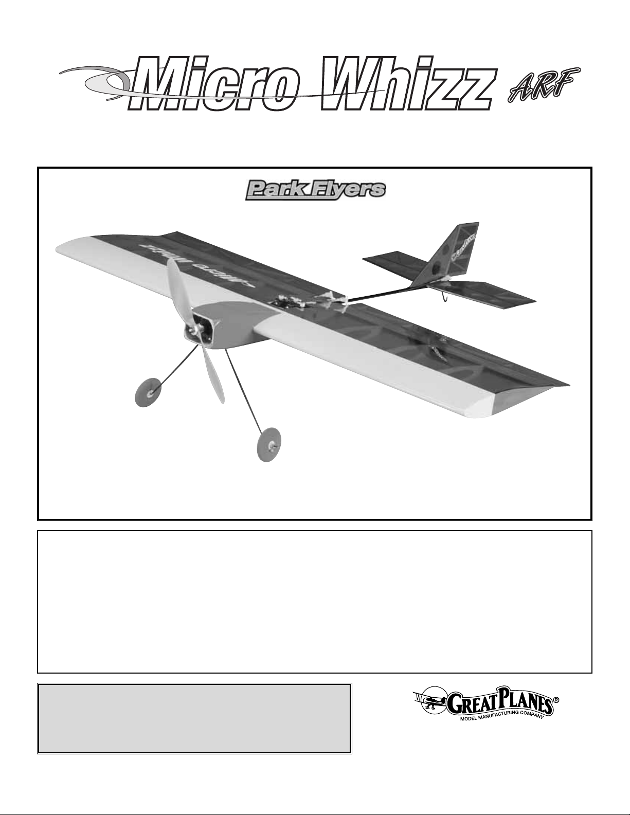
Wingspan: 32 in [813mm]
Wing Area: 352 sq in [23 dm
2
]
Weight: 18 oz [510 g]
Wing Loading: 7.4 oz/sq ft [22 g/dm
2
]
Length: 25-3/4 in [654mm]
Radio: 4-Channels
Motor: ElectriFly
™
S-280 5:1 Ratio STD Gearbox,
ElectriFly Ferrite BB Motor
™
Page 2
INTRODUCTION ..........................................................................2
SAFETY PRECAUTIONS.............................................................2
TOOLS & SUPPLIES REQUIRED ...............................................3
Hardware & Accessories.......................................................3
IMPORTANT BUILDING NOTES.................................................3
COMMON ABBREVIATIONS.......................................................4
ORDERING REPLACEMENT PARTS .........................................4
METRIC/INCH RULER .................................................................4
KIT CONTENTS...........................................................................5
ASSEMBLY OF THE MODEL......................................................6
Installing the Tail Surfaces .....................................................6
Assembly of the Fuselage/Wing ............................................8
Installing the Motor................................................................9
Installing the Servos..............................................................9
Installing the Receiver & Speed Control .............................11
Apply the Decals .................................................................11
GET THE MODEL READY TO FLY............................................11
Check the Control Directions...............................................11
Set the Control Throws........................................................12
Balance the Model (C.G.) ....................................................12
Balance the Model Laterally................................................13
PREFLIGHT ...............................................................................13
Identify Your Model ..............................................................13
Charge the Batteries ...........................................................13
Balance the Propellers ........................................................13
Ground Check .....................................................................13
Range Check .......................................................................14
MOTOR SAFETY PRECAUTIONS............................................14
AMA SAFETY CODE.................................................................14
CHECK LIST..............................................................................14
FLYING .......................................................................................15
Takeoff .................................................................................15
Flight....................................................................................15
Landing................................................................................15
The Great Planes Micro Whizz™ARF is a high quality, fun
flying electric ARF R/C park flyer. If you are able to
successfully fly an advanced trainer-type R/C airplane on
your own, you should feel confident flying your electric
Micro Whizz. Do bear in mind that this airplane is capable
of all aerobatic maneuvers.Therefore, you must realize that
it may be a bit quicker on its responses than some trainer
type airplanes you might be accustomed to. Smaller,
lightweight park flyers like the Micro Whizz fly best in no
wind or very light wind conditions.
If you are a first time R/C pilot, seek the guidance of an
experienced R/C pilot before flying your Micro Whizz.
We hope your Great Planes Micro Whizz ARF will bring you
many hours of R/C flying enjoyment.
For the latest technical updates or manual corrections to the
Great Planes Micro Whizz ARF, visit the web site listed
below and select the Great Planes Micro Whizz ARF.If
there
is new technical information or changes to this model a
“tech
notice” box will appear in the upper left corner of the page.
http://www.greatplanes.com/airplanes/index.html
1. Your Great Planes Micro Whizz ARF should not be
considered a toy, but rather a sophisticated, working model
that functions very much like a full-size airplane.Because of
its performance capabilities, the Great Planes Micro Whizz
ARF, if not assembled and operated correctly, could
possibly cause injury to yourself or spectators and damage
to property.
2. You must assemble the model according to the
instructions. Do not alter or modify the model, as doing so
may result in an unsafe or unflyable model. In a few cases
the instructions may differ slightly from the photos.In those
instances the written instructions should be considered
as correct.
3.You must take time to build straight, true and strong.
4. You must use an R/C radio system that is in first-class
condition and a correctly sized motor and components
(batteries, wheels, etc.) throughout the assembly process.
5.You must correctly install all R/C and other components
so that the model operates correctly on the ground and in
the air.
6.You must check the operation of the model before every
flight to insure that all equipment is operating and that the
model has remained structurally sound. Be sure to check
clevises or other connectors often and replace them if they
show any signs of wear or fatigue.
7. If you are not already an experienced R/C pilot, you
should fly the model only with the help of a competent,
experienced R/C pilot.
Remember: Take your time and follow the instructions
to end up with a well-built model that is straight and
true.
We, as the manufacturer, provide you with a top quality
product and instructions, but ultimately the quality and
flyability of your finished model depends on how y ou build
it; therefore, we cannot in any way guarantee the
performance of your completed model, and no
representations are expressed or implied as to the
performance or safety of your completed model.
PRO TECT YOUR MODEL,YOURSELF
& OTHERS...FOLLOW THESE
IMPORTANT SAFETY PRECAUTIONS
INTRODUCTION
TABLE OF CONTENTS
2
Page 3
If you have not flown this type of model before, we
recommend that you get the assistance of an experienced
pilot in your R/C club for your first flights. If you’re not a
member of a club, your local hobby shop has information
about clubs in your area whose membership includes
experienced pilots.
In addition to joining an R/C club, we strongly recommend y ou
join the AMA (Academy of Model Aeronautics). AMA
membership is required to fly at AMA sanctioned clubs.There
are over 2,500 AMA chartered clubs across the country.
Among other benefits, the AMA provides insurance to its
members who fly at sanctioned sites and events. Additionally,
training programs and instructors are available at AMA club
sites to help you get started the right way. Contact the AMA at
the address or toll-free phone number below:
❏ Hobby knife (HCAR0105)
❏ #11 blades (HCAR0211)
❏ Needle-nose pliers
❏ Pliers with wire cutters (HCAR0630)
❏ Small Phillips head screwdriver
❏ Medium-sized flat-head screwdriver
❏ Small piece of medium grade sandpaper
❏ Ruler
❏ Electric drill and 1mm drill bit
❏ 6-minute Epoxy (GPMR6045)
❏ Denatured alcohol (for epoxy clean up)
❏ 1/2 oz. Medium Pro
™
CA (GPMR6007)
❏ CA debonder
❏ Pro Wood Glue (GPMR6160)
❏ Great Planes 1" x 6" Velcro
®
(GPMQ4480)
❏ Top Flite
®
Panel Line Pen (TOPQ2510)
❏ Great Planes Silver Solder Kit (GPMR8070)
❏ Hobbico
®
Soldering Iron (HCAR0776)
❏ 1/16" [1.6mm] x 3/4" [19mm] x 4" [102mm] scrap balsa
❏ 3/32" [2.4mm] x 1" [25mm] x 4" [102mm] scrap balsa
This is the list of hardware and accessories required to
finish the Great Planes Micro Whizz ARF. Order numbers
are provided in parentheses.
• When you see the term
test fit
in the instructions, it
means that you should first position the part on the
assembly without using any glue, then slightly modify or
custom fit
the part as necessar y for the best fit.
• Whenever the term
glue
is written you should rely upon
your experience to decide what type of glue to use.When a
specific type of adhesive works best for that step, the
instructions will make a recommendation.
IMPORTANT BUILDING NOTES
Motor/Gearbox/Prop
The Micro Whizz ARF was flown extensively with an
ElectriFly™S-280 5:1 Ratio STD Gearbox unit
(GPMG0200).The ElectriFly Ferrite BB Motor
(GPMG0305)
was used for power along with an APC 9 x 6 SloFly
Propeller (APCQ5013). This set-up also requires a 3mm
Shaft Adapter (GPMQ4600). This is an excellent power
unit for this airplane.
Battery Recommendations
The Micro Whizz operates best using the 8-cell NiMH
from ElectriFly (GPMP0072)
Radio Equipment
The Micro Whizz requires a mini receiver such as the
ElectriFly 4 channel FM Mini Receiver (GPML0045) and
3 Futaba®S-3103 Micro Mini Servos (FUTM0037).
Speed Control
An electronic speed control with BEC (Battery Eliminator
Circuitry) is required.The BEC allows both the motor and
the radio system to be powered by the same battery and
eliminates the additional battery required to power the
radio gear. The ElectriFly C-10 Mini Electronic Speed
Control (GPMM2010) is recommended for the Micro
Whizz.
Chargers
The best type of charger to use is a peak charger,
because it charges the batteries until they are fully
charged, then automatically switches to a trickle charge
mode. The Great Planes ElectriFly Peak Charger
(GPMM3000) is suitable for nickel-metal hydride
batteries, NiCds and transmitter battery packs.
You may want to consider the ElectriFly Triton
™
computerized charger, discharger, and cycler
(GPMM3150). This unit will pay great dividends by
extending battery life and is capable of charging virtually
every hobby battery on the market today.
Hardware & Accessories
TOOLS & SUPPLIES REQUIRED
Academy of Model Aeronautics
5151 East Memorial Drive
Muncie, IN 47302
Tele: (800) 435-9262
Fax (765) 741-0057
Or via the Internet at:
http://www.modelaircraft.org
3
Page 4
• Whenever just
epoxy
is specified you may use either
30-minute (or 45-minute) epoxy or 6-minute epoxy. When
30-minute epoxy is specified it is highly recommended that
you use only 30-minute (or 45-minute) epoxy, because you
will need the working time and/or the additional strength.
•
Photos and sketches
are placed before the step they
refer to. Frequently you can study photos in following steps
to get another view of the same parts.
Fuse = Fuselage
Stab = Horizontal Stabilizer
Fin = Ver tical Fin
LE = Leading Edge
TE = Trailing Edge
LG = Landing Gear
" = Inches
mm = millimeters
COMMON ABBREVIATIONS
4
To order replacement parts for the Great Planes Micro Whizz ARF, use the order numbers in the Replacement Parts List
that follows. Replacement par ts are available only as listed. Not all parts are available separately (an aileron cannot be
purchased separately, but is only available with the wing kit).Replacement par ts are not available from Product Support,
but can be purchased from hobby shops or mail order/Internet order firms. Hardware items (screws, nuts, bolts) are also
available from these outlets. If you need assistance locating a dealer to purchase parts, visit www.greatplanes.com and
click on “Where to Buy.” If this kit is missing parts, contact Great Planes Product Support.
Replacement Parts List
Order Number
Description How to Pur
chase
Missing pieces.....................Contact Product Suppor t
Instruction manual...............Contact Product Support
Full-size plans.....................Not available
GPMA2600 Wing Kit
GPMA2601 Fuse (Nose Section)
GPMA2602 Tail Rod
GPMA2603 Tail Set
GPMA2604 Landing Gear Set
GPMA2605 Hardware Set
ORDERING REPLACEMENT PARTS
................
Contact Your Hobby
Supplier to Purchase
These Items
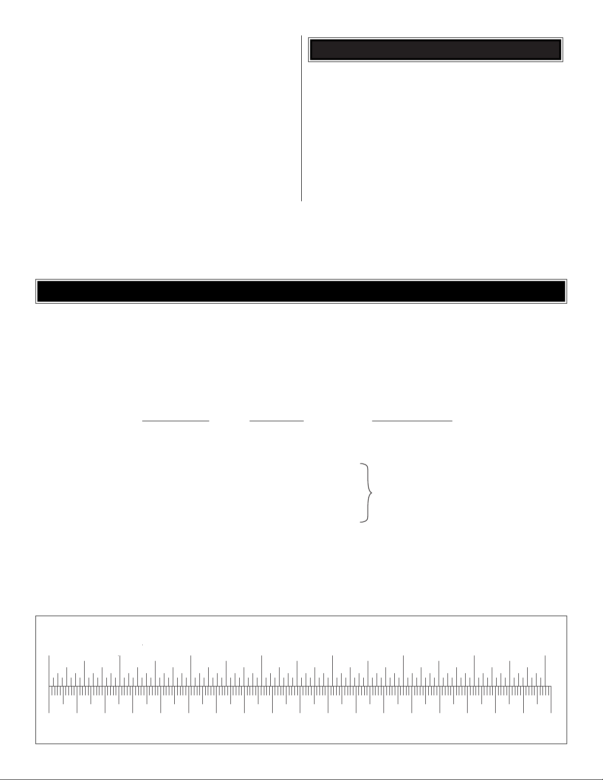
0" 1" 2" 3" 4" 5" 6" 7"
0 10 20 30 40 50 60 70 80 90 100 110 120 130 140 150 160 170 180
Inch Scale
Metric Scale
To convert inches to millimeters, multiply inches by 25.4
Page 5
5
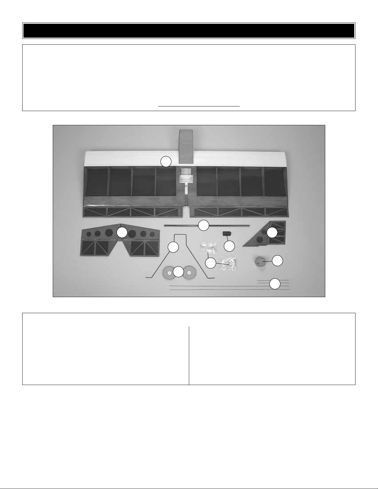
1. Fuselage/Wing w/Ailerons
2. Horizontal Stabilizer w/Elevators
3. Fin w/Rudder
4. Carbon Fiber Tail Boom
5. Tail Bracket
6. Landing Gear
7. Wheels
8. Pushrods (4)
9. Spinner
10. Small Parts Bags (2)
Kit Contents
Before starting to build, use the Kit Contents list to take an inventory of this kit to make sure it is complete, and inspect the
parts to make sure they are of acceptable quality. If any parts are missing or are not of acceptable quality, or if you need
assistance with assembly, contact Great Planes Product Support. When reporting defective or missing parts, use the part
names exactly as they are written in the Kit Contents list on this page.
Great Planes Product Support:
Telephone: (217) 398-8970
Fax: (217) 398-7721
E-mail: air
support@greatplanes.com
KIT CONTENTS
1
2
4
7
8
6
3
10
5
9
Page 6

❏ 1. Locate the carbon fiber tail boom and note the pre-cut
slot for the pushrods to exit. Cut a piece of 1/16" [1.6mm]
balsa 3/4" [19mm] x 4" [102mm].Also cut 2 squares of 3/32"
[2.4mm] balsa 1" [25mm] x 1" [25mm]. Note: Wood not
supplied with kit.
❏ 2. Slide the 1/16" balsa strip into the pre-cut slot. Place
this onto a flat surface and slide the 3/32" balsa squares
under the strip as shown in the above photograph. Locate
the tail bracket and test fit it into place on the end of the tail
boom making sure that both sides of the bracket touch the
flat surface.Make sure that the bracket is flush with the rear
of the tail boom and the pre-cut slot in the bracket is facing
toward the rear.When satisfied with the fit, glue the bracket
into place using medium CA.
❏ 3.With a 3/64" [1mm] bit, drill a hole in the tail boom at
the forward end of the pre-cut slot in the bracket.
❏ 4.Use a sharp hobby knife to cut the cov ering awa y from the
slot in the center of the leading edge of the horizontal stabilizer.
❏ 5. Measure the width of the horizontal stabilizer and
mark a centerline on the bottom of the stabilizer with a felttipped pen as shown above.
❏ 6.Measure 3/16" [5mm] forward from the trailing edge of the
horizontal stabilizer at the centerline and mark this location.
Installing the Tail Surfaces
ASSEMBLY OF THE MODEL
6
Page 7

❏ 7.With the horizontal stabilizer placed bottom up on a flat
surface, place the tail boom (with the bracket attached) on
top of the stabilizer as shown in the abov e photog raphs with
the rear of the assembled tail boom positioned on the
centerline and the 3/16" [5mm] mark. Make the correct
alignment by measuring the distance from the tip of the tail
boom to both forward corners of the horizontal stab. Make
the necessary
adjustments until both measurements are
equal on both
sides.
❏ 8. When you are satisfied with the correct position of the tail
boom, mark the position of the bracket onto the stabilizer.
❏ 9. Using a shar p hobby knife cut away the covering just
inside the lines you drew on the cov ering.Do not cut into the
balsa as this will weaken the structure. Glue the tail boom
into place with CA. While the glue cures check the
positioning with a ruler in the same way as when you
marked the location.
❏ 10. Cut a slot into the right elevator at a point 3/16"
[5mm] toward the outer end of the elevator from the inside
edge of the elevator. Place the control horn into the slot in a
manner that allows the holes in the horn to align with the
hinge line as shown in the above photograph. Make sure
that the horn is placed on top of the elevator.When you are
satisfied with the placement, glue it into place with CA.
❏ 11.Place the fin/rudder into the slot on top of the
horizontal
stabilizer.Use a felt-tipped pen and mark the position on
both
the fin and the stabilizer as shown in the photograph above.
❏ 12. Using the same procedure as before, cut the covering
away from the top of the stabilizer as shown in the
photograph above. Do the same with the base of the fin
where you made the marks.Before gluing the fin/rudder into
place in the next step, position the control horn for the
rudder into the left side of the rudder and glue the control
horn into place with CA.
7
Page 8

❏ 13.Apply CA to the areas where you removed the
covering
and into the slot in the stabilizer. Slide the fin/rudder into
position and place a 90° tool onto the top of the stabilizer
holding the fin in place until the glue sets as shown in the
above photograph.
❏ 14.Test fit the tail boom into the hole on the wing trailing
edge. Place the assembly onto a flat surface and move the
assembled tail section forward and aft until the
measurement from the hinge line of the elevators to the
hinge line of the ailerons is 11-1/2" [292mm]. Measure the
distance from both sides of the horizontal stabilizer to the
table
surface. Adjust the tail boom until these measurements are
equal.Carefully mark the location of the tail boom in the
wing.
❏ 15. When satisfied with the fit and position of the tail
assembly, remove it and apply CA inside the hole. Then
return the tail assembly to the correct position. Make sure
that the position is right before the CA has cured.
❏ 1. As shown in the photograph above, install the two
control horns in the ailerons by cutting a small portion of the
aileron away with a sharp hobby knife. Use sandpaper to
rough up the areas where the control horns will be glued.
Make sure the holes line up with the hinge line. When you
are satisfied with the position, glue it into place with CA.
❏ 2. To install the landing gear, first fit the wheels onto the
axle portion of the gear.Slip the wheel collars onto the axle.
Insert the Phillips head screws into the wheel collar and
tighten them securely. Use the photograph above as a
guide.
❏ 3. Place the airplane on your work surface upside-down.
Using a sharp hobby knife, remove the covering over the
opening in the wood where the gear is placed. As shown in
the photograph above , place the landing gear into the slot in
the bottom of the fuselage.
Assembly of the Fuselage/Wing
8
Page 9

❏ 4. Locate and test fit the tail skid into the hole you drilled
earlier at the forward end of the slot in the bracket under the
horizontal stabilizer. When satisfied with the fit glue it into
place with CA.
❏ 1. Locate the brass gear and the small tube of green
adhesive.Test fit the gear onto the motor shaft. If you are finding
no problems with the fit, place a drop of the adhesive from the
small tube into the hole in the center of the gear.Before the glue
sets, position the gear on the shaft at a location where the end
of the motor shaft is flush with the end of the gear. Let the
adhesive cure for an hour before proceeding.
❏ 2. When the adhesive has cured completely, inser t the
motor all the way into the gear drive unit.This is a tight fit
and you will also have to move the gear box back and forth
to allow the pinion gear to slide all the way into alignment.
❏ 3. Slide the motor/gear drive assembly into the nose of
the airplane. Mark the location of the mounting holes onto
the firewall.Remove the unit and drill 1/16" [1.5mm] holes at
the marked locations. Mount the assembly as shown above
with #2 x 3/8" [13mm] screws.
❏ 4. Install the collet, propeller adapter, and the propeller
as shown in the photograph above.
❏ 1. Install the three servos in the position shown in the
above photograph. Follow the directions included with your
particular ser vos for the proper mounting.
Installing the Servos
Installing the Motor
9
Page 10

❏ 2.Gather the four pushrods, threaded couplers, clevises,
and clevis retainers as shown in the above photograph.
❏ 3.Prepare the pushrods for assembly by sanding or filing
one end of each pushrod. Use silver solder to attach the
threaded couplers to the end you have sanded on each of
the four pushrods. Follow the instructions with the silver
solder carefully.
❏ 4.Place a clevis and clevis retainer on each of the
pushrods
as shown.
❏ 5.Insert the rudder and elevator pushrods into the slot in
the tail boom. Snap the clevis onto the elevator and rudder
control horns as shown in the photograph above.
❏ 6.Position the rudder so that it is directly aligned with the
fin. As indicated in the photograph above, place a bend in
the pushrod in the location shown. Again, make sure that
the fin is in exact alignment and make a “Z” bend in the
pushrod where the pushrod meets the holes in the centered
servo arm. Repeat this process for the elevator pushrod.
❏ 7.Use the same procedure to connect the aileron
pushrods.
Your completed assembly should look the same as shown in
the preceding photographs.
10
Page 11

❏ 1. The areas where you will be mounting your receiver,
speed control, and battery must have a thin coating of glue
to allow the Velcro to attach.You can use CA or any type of
wood glue for this purpose. Allow the glue to dry or cure
completely before attaching the Velcro. Note the location of
the mounted speed control in the above photograph.
❏ 2. The photograph illustrates the placement of the
receiver. Place a 1/16" [1.6mm] hole close to the receiver in
the bottom of the fuselage. Feed the antenna through this
hole and tape it into place on the wing.
❏ 3. Note the installation and position of the battery pack.
❏ 4. Install the hatch.
1.Use scissors or a sharp hobby knife to cut the decals from
the sheet.
2. Be certain the model is clean and free from oily
fingerprints and dust. Prepare a dishpan or small bucket
with a mixture of liquid dish soap and warm water–about
one teaspoon of soap per gallon of water. Submerse the
decal in the soap and water and peel off the paper backing
while the decal is in the soapy water. Note: Even though the
decals have a “sticky-back” and are not the water transfer
type, submersing them in soap & water allows accurate
positioning and reduces air bubbles underneath.
3. Position decal on the model where desired. Hold the
decal down and use a paper towel to wipe most of the
water away.
4. Use a piece of soft balsa or something similar to
squeegee remaining water from under the decal. Apply the
rest of the decals the same way.
Note: For safety reasons, remove the propeller from the
airplane before proceeding.
❏ 1. Tur n on the transmitter and receiver and center the
trims. If necessary, remove the servo arms from the servos
and reposition them so they are centered. Reinstall the
screws that hold on the servo arms.
❏ 2.While the transmitter and receiver are still on, check all the
control surfaces to see if they are centered.If necessary, adjust
the clevises on the pushrods to center the control surfaces.
❏ 3. Make cer tain that the control surfaces respond in the
correct direction as shown in the diagram. If any of the
controls respond in the wrong direction, use the servo
Check the Control Directions
GET THE MODEL READY TO FLY
Apply the Decals
Installing the Receiver
& Speed Control
11
4-CHANNEL
TRANSMITTER
4-CHANNEL
TRANSMITTER
4-CHANNEL
TRANSMITTER
4-CHANNEL
TRANSMITTER
Page 12

reversing in the transmitter to reverse the servos connected
to those controls. Be certain the control surfaces have
remained centered. Adjust if necessary.
Use a Great Planes AccuThrow™(or a ruler) to accurately
measure and set the control throw of each control surface
as indicated in the chart that follows. If your radio does not
have dual rates, we recommend setting the throws at the
low rate setting.
Note:The throws are measured at the widest part of the
elevators, rudder and ailerons.
When you have completed this section, replace the
propeller onto the airplane.
At this stage the model should be in ready-to-fly condition
with all of the systems in place including the motor, landing
gear, battery, and the radio system.
❏ 1. Use a felt-tip pen or 1/8"-wide tape to accurately mark
the C.G. on the bottom of the wing on both sides of the
fuselage. The C.G. is located 2-1/2" [64mm] back from the
leading edge of the wing.
This is where your model should balance for the first
flights. Later, you may wish to experiment by shifting the
C.G. up to 2-3/8" [67mm] forward or 3" [76mm] back to
change the flying characteristics.Moving the C.G.forward
may improve the smoothness and stability, but the model
may then require more speed for takeoff and make it
more difficult to slow for landing. Moving the C.G. aft
makes the model more maneuverable, but could also
cause it to become too difficult to control. In any case,
start at the recommended balance point and do not at
any time balance the model outside the specified range.
More than any other factor, the C.G. (balance point) can
have the greatest effect on how a model flies, and may
determine whether or not your first flight will be
successful. If you value this model and wish to enjoy it for
many flights, DO NOT OVERLOOK THIS IMPORTANT
PROCEDURE. A model that is not properly balanced will
be unstable and possibly unflyable.
Balance the Model (C.G.)
IMPORTANT: The Great Planes Micro Whizz ARF has
been extensively flown and tested to arrive at the throws
at which it flies best. Flying your model at these throws
will provide you with the greatest chance for successful
first flights. If, after you have become accustomed to the
way the Great Planes Micro Whizz ARF flies, you would
like to change the throws to suit your taste, that’s fine.
However, too much control throw could make the model
difficult to control, so remember, “More is not always
better.”
These are the recommended control surface throws:
High Rate Low Rate
ELEVATOR: 1" [25mm] up 5/8" [16mm] up
1" [25mm] down 5/8" [16mm] down
RUDDER: 13/16" [20mm] right 5/8" [16mm] right
13/16" [20mm] left 5/8" [16mm] left
AILERONS: 1" [25mm] up 5/8" [16mm] up
1" [25mm] down 5/8" [16mm] down
Set the Control Throws
12
Page 13

❏ 2.With all parts of the model installed (ready to fly), place
the model on a Great Planes CG Machine, or lift it at the
balance point you marked.
❏ 3.If the tail drops, the model is “tail hea vy”and the
battery
pack and/or receiver must be shifted forward or weight must
be added to the nose to balance. If the nose drops, the
model is “nose heavy” and the batter y pack and/or receiver
must be shifted aft or weight must be added to the tail to
balance. If possible, relocate the battery pack and receiver
to minimize or eliminate any additional ballast required.
Begin by placing incrementally increasing amounts of
weight on the airplane until the model balances. Once you
have determined the amount of weight required, it can be
permanently attached.
Note: Do not rely upon the adhesive on the back of the lead
weight to permanently hold it in place. Use #2 sheet metal
screws, RTV silicone or epoxy to permanently hold the
weight in place.
❏ 4. IMPORTANT: If you found it necessary to add any
weight, recheck the C.G.after the weight has been installed.
❏ 1. With the wing level, have an assistant help you lift the
model by the motor propeller shaft and the bottom of the
fuse under the TE of the fin.Do this several times.
❏ 2.If one wing always drops when you lift the model, it means
that side is heavy. Balance the airplane by adding weight to the
other wing tip.An air plane that has been laterally balanced will
track better in loops and other maneuvers.
No matter if you fly at an AMA sanctioned R/C club site or if
you fly somewhere on your own, you should always have
your name, address, telephone number and AMA number
on
or inside your model.It is required at all AMA R/C club flying
sites and AMA sanctioned flying events .Fill out the
identification
tag on the back cover page and place it on or inside y our
model.
Follow the battery charging instructions that came with your
radio control equipment to charge the transmitter battery.
You should always charge your transmitter batteries the
night before you go flying, and at other times as
recommended by the radio manufacturer.
Carefully balance your propeller and spare propellers before
you fly. An unbalanced prop can be the single most
significant cause of vibration that can damage your model.
Not only will motor mounting screws and bolts loosen,
possibly with disastrous effect, but vibration may also
damage your radio receiver and battery.
We use a Top Flite Precision Magnetic Prop Balancer
™
(TOPQ5700) in the workshop and keep a Great Planes
Fingertip Prop Balancer (GPMQ5000) in our flight box.
If the motor is new, follow the motor manufacturer’s
instructions to break-in the motor. After break-in, confirm
that the motor transitions smoothly and rapidly to full power
and maintains full power-indefinitely. After you run the motor
on the model, inspect the model closely to make sure the
prop is secure and all pushrods and connectors are secure.
Ground Check
Balance the Propellers
Charge the Batteries
Identify Y our Model
PREFLIGHT
Balance the Model Laterally
13
Page 14

Ground check the operational range of your r adio bef ore the
first flight of the day. With the transmitter antenna collapsed
and the receiver and transmitter on, you should be able to
walk at least 100 feet away from the model and still have
control. Have an assistant stand by your model and, while
you work the controls, tell you what the control surfaces are
doing. Repeat this test with the motor running at various
speeds with an assistant holding the model, using hand
signals to show you what is happening. If the control
surfaces do not respond correctly, do not fly! Find and
correct the problem first. Look for loose servo connections
or broken wires, corroded wires on old servo connectors,
poor solder joints in your battery pack or a defective cell, or
a damaged receiver crystal from a previous crash.
Get help from an experienced pilot when learning to
operate motors.
Use safety glasses when running motors.
Do not run the motor in an area of loose gravel or sand;the
propeller may throw such material in your face or eyes.
Keep your f ace and body as well as all spectators a wa y from
the plane of rotation of the propeller as you run the motor.
Keep these items away from the prop: loose clothing, shir t
sleeves, ties, scarfs, long hair or loose objects such as
pencils or screwdrivers that may fall out of shirt or jacket
pockets into the prop.
The motor gets hot! Do not touch it during or right after
operation.
Read and abide by the following Academy of Model
Aeronautics Official Safety Code:
GENERAL
1. I will not fly my model aircraft in sanctioned events, air
shows, or model flying demonstrations until it has been
proven to be airworthy by having been previously
successfully flight tested.
2. I will not fly my model aircraft higher than approximately
400 feet within 3 miles of an airport without notifying the
airport operator.I will give right of way to, and avoid flying in
the proximity of full-scale aircraft. Where necessary an
observer shall be used to supervise flying to avoid having
models fly in the proximity of full-scale aircraft.
3.Where established, I will abide by the safety rules for the
flying site I use, and I will not willfully and deliberately fly my
models in a careless, reckless and/or dangerous manner.
4. I will not fly my model unless it is identified with my name
and address or AMA number, on or in the model.
5. I will not operate models with pyrotechnics (any device
that explodes, burns, or propels a projectile of any kind).
RADIO CONTROL
1.I will have completed a successful radio equipment
ground
check before the first flight of a new or repaired model.
2. I will not fly my model aircraft in the presence of
spectators until I become a qualified flier, unless assisted b y
an experienced helper.
3. I will perform my initial turn after takeoff away from the pit
or spectator areas, and I will not thereafter fly over pit or
spectator areas, unless beyond my control.
4. I will operate my model using only radio control
frequencies
currently allowed by the Federal
Communications Commission.
❏ 1. Check the C.G. according to the measurements
provided in the manual.
❏ 2. Be cer tain the battery, speed control, and receiver
are securely mounted in the fuse. Simply stuffing
them into place with foam rubber is not sufficient.
❏ 3. Extend your receiver antenna and make sure it has
been properly attached to the airplane.
❏ 4. Balance your model laterally as explained in the
instructions.
❏ 5. Use thread locking compound to secure critical
fasteners such as the set screws that hold the wheel
collars.
❏ 6. Add a drop of oil to the axles so the wheels will
turn freely.
During the last few moments of preparation your mind
may be elsewhere anticipating the excitement of the first
flight. Because of this, you may be more likely to overlook
certain checks and procedures that should be performed
before the model is flown.To help avoid this, a check list
is provided to make sure these important areas are not
overlooked. Many are covered in the instruction manual,
so where appropriate, refer to the manual for complete
instructions.
CHECK LIST
AMA SAFETY CODE (excerpt)
Failure to follow these safety precautions may result
in severe injury to yourself and others.
MOTOR SAFETY PRECAUTIONS
Range Check
14
Page 15

❏ 7.Reinforce holes for wood screws with thin CA where
appropriate, such as servo mounting screws.
❏ 8.Confirm that all controls operate in the correct direction
and the throws are set up according to the manual.
❏ 9. Make sure there are silicone retainers on all the
clevises and that all servo arms are secured to the
servos with the screws included with your radio.
❏ 10.Balance your propeller (and spare propellers).
❏ 11.Tighten the propeller nut and spinner.
❏ 12.Place your name, address, AMA number and
telephone number on or inside your model.
❏ 13. If you wish to photograph your model, do so before
your first flight.
❏
14. Range check your radio when you get to the flying
field.
The Great Planes Micro Whizz ARF is a great-flying model
that flies smoothly and predictably. The Great Planes Micro
Whizz ARF does not, however, possess the self-recovery
characteristics of a primary R/C trainer and should be flown
only by experienced R/C pilots.
Before you get ready to takeoff, see how the model handles
on the ground by doing a fe w practice runs at low speeds on
the runway. Check all fasteners and control linkages for
peace of mind.
Remember to takeoff into the wind.When you’re ready, point
the model straight down the runway, hold a bit of up elevator
and then gradually advance the throttle.As the model gains
speed decrease up elevator allowing the tail to come off the
ground. One of the most important things to remember with
a tail dragger is to always be ready to apply right rudder to
counteract motor torque. Gain as much speed as your
runway and flying site will practically allow before gently
applying up elevator, lifting the model into the air. At this
moment it is likely that you will need to apply more right
rudder to counteract motor torque. Be smooth on the
elevator stick, allowing the model to establish a gentle climb
to a safe altitude before turning into the traffic pattern.
For reassurance and to keep an eye on other traffic, it is a
good idea to have an assistant on the flight line with you.Tell
him to remind you to throttle back once the plane gets to a
comfortable altitude.While full throttle is usually desirable
for
takeoff, most models fly more smoothly at reduced
speeds.
Take it easy with the Great Planes Micro Whizz ARF for the
first few flights, gradually getting acquainted with it as you
gain confidence. Adjust the trims to maintain straight and
level flight.After flying around for a while, and while still at a
safe altitude, practice slow flight and execute practice
landing approaches by reducing the throttle to see how the
model handles at slower speeds.Add power to see how she
climbs as well. Continue to fly around, executing various
maneuvers and making mental notes (or having your
assistant write them down) of what trim or C.G. changes
may be required to fine tune the model so it flies the wa y you
like.Monitor your battery charge level, but use this first flight
to become familiar with your model before landing.
To initiate a landing approach, lower the throttle while on the
downwind leg. Allow the nose of the model to pitch
downward to gradually bleed off altitude. Continue to lose
altitude, but maintain airspeed by k eeping the nose do wn as
you turn onto the crosswind leg.Make your final turn toward
the runway (into the wind) keeping the nose down to
maintain
airspeed and control. Level the attitude when the model
reaches the runway threshold, adjusting the throttle as
necessary to maintain your glide path and airspeed. If you
are going to overshoot, smoothly advance the throttle
(always
ready on the right rudder to counteract torque) and climb out
to make another attempt. When you’re ready to make your
landing flare and the model is a foot or so off the deck,
smoothly increase up elevator until it gently touches down.
One final note about flying your model: Have a goal or flight
plan in mind for every flight. This can be learning a new
maneuver(s), improving a maneuver(s) y ou already know, or
learning how the model behaves in certain conditions (such
as on high or low rates).This is not necessarily to improve
your skills
(though it is never a bad idea!)
, but more
importantly so you do not surprise yourself by impulsively
attempting a maneuver and suddenly finding that you’ve run
out of time, altitude or airspeed. Every maneuver should be
deliberate, not impulsive.For example, if you’re going to do
a loop, check your altitude, mind the wind direction
Landing
Flight
Takeoff
CAUTION (THIS APPLIES TO ALL R/C AIRPLANES): If,
while flying, you notice any unusual sounds, such as a
low-pitched “buzz,” this may indicate control surface
flutter.Because flutter can quickly destroy components of
your airplane, any time you detect flutter you must
immediately cut the throttle and land the airplane! Check
all servo grommets for deterioration (this may indicate
which surface fluttered), and make sure all pushrod
linkages are secure and free of play. If the control surface
fluttered once, it probably will flutter again under similar
circumstances unless you can eliminate the free-play or
flexing in the linkages. Here are some things which can
cause flutter: Excessive hinge gap; Not mounting control
horns solidly; Poor fit of clevis pin in horn; Side-play of
pushrod in guide tube caused by tight bends; Poor fit of
Z-bend in servo arm; excessive play or backlash in servo
gears; and insecure servo mounting.
FLYING
15
Page 16

(anticipating rudder corrections that will be required to
maintain heading), remember to throttle back at the top, and
make certain you are on the desired rates (high/low rates).
A flight plan greatly reduces the chances of crashing your
model just because of poor planning and impulsive moves.
Remember to think.
Have a ball! But always stay in control and fly in a
safe manner.
GOOD LUCK AND GREAT FLYING!
Great Planes ElectriFly S-280 Ferrite BB Motor
Compact electric park flyer models demand high power in
an efficient package – and it’s supplied by this 7.2 – 8.4V,
speed 280-size motor from ElectriFly. Among its features
are ball bearings, a single-wind armature, factory-installed
capacitors, and a factory-installed 2-pin connector designed
to plug into Great Planes ElectriFly C-5 or C-10 electronic
speed controls. GPMG0305
Great Planes ElectriFly S-280 Gearbox
Developed for low noise and low maintenance, this Great
Planes ElectriFly gearbox features a 5:1 gear ratio and uses
standard bronze bushings for long-lasting sport use. A
lightweight, fiber-reinforced, sealed gear case resists
damage
and keeps out dust and debris.Paired with a 280-size motor,
it helps draw the maximum climbing power and flight times
from every battery mAh. It uses a brass pinion gear for
strength and a nylon main gear for quiet, low-friction
operation. GPMG0200
Great Planes ElectriFly Peak Charger
Designed for small, lightweight electrics and transmitter
batteries, this charger can also be used with any 6 – 8-cell
NiCd or NiMH pack.It plugs into a power supply or cigarette
lighter for fast charges. Pulsed current charging protects
small packs from overheating. Charge rate adjusts to 200
mAh or 600mAh. A 15mA trickle charge keeps packs
topped off for use anytime. Includes 2-pin connector for
ElectriFly packs; adapters available separately. 1-year
warranty. GPMM3000
OTHER ITEMS AVAILABLE FROM
GREAT PLANES
 Loading...