

Page 1
WARRANTY
Great Planes
®
Model Manufacturing Co. guarantees this kit to be free from defects in both material and workmanship at the date of
purchase.This warranty does not cover any component parts damaged by use or modification. In no case shall Great Planes' liability
exceed the original cost of the purchased kit. Further, Great Planes reserves the right to change or modify this warranty without notice.
In that Great Planes has no control over the final assembly or material used for final assembly, no liability shall be assumed nor
accepted for any damage resulting from the use by the user of the final user-assemb led product.By the act of using the user-assembled
product, the user accepts all resulting liability.
If the buyer is not prepared to accept the liability associated with the use of this product, the buyer is advised to return this
kit immediately in new and unused condition to the place of purchase.
READ THROUGH THIS MANUAL BEFORE
STARTING CONSTRUCTION. IT CONTAINS
IMPORTANT WARNINGS AND INSTRUCTIONS
CONCERNING THE ASSEMBLY AND USE OF
THIS MODEL.
GPMZ0218 for GPMA1101 V1.0© Copyright 2003, Printed in Thailand
Champaign, Illinois
(217) 398-8970, Ext 5
airsupport@greatplanes.com
INSTRUCTION MANUAL
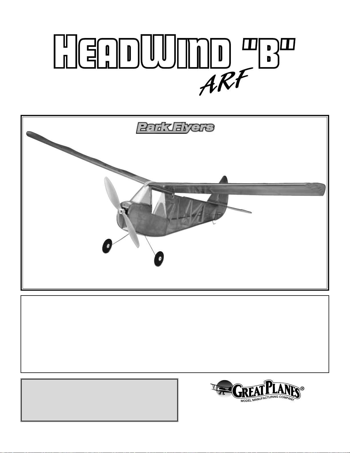
Wingspan: 47 in [1195mm]
Wing Area: 264 sq in [17 dm²]
Weight: .75 lbs [340 g]
Wing Loading: 7 oz/sq ft [22 g/dm²]
Length: 26 in [660mm]
Radio: 3-channel with 8-cell 2/3AA NiCD airborne pack, 2 micro servos
Motor: 280 with Gear Drive and Electronic Speed Control (ESC)
CG: 1-3/4" [45mm] back from leading edge with a range of
1-1/2" [38mm] to 2" [51mm]
Throws: Elevator 1/2" up 1/2" down
Rudder 1" up 1" down
Page 2
INTRODUCTION................................................................2
SAFETY PRECAUTIONS..................................................2
ADDITIONAL ITEMS REQUIRED.....................................3
Radio Equipment ................................................................3
Speed Control ....................................................................3
Motor System.....................................................................3
Battery Recommendations.................................................3
Chargers.............................................................................3
Adhesives and Building Supplies.......................................4
Covering Accessories.........................................................4
Optional Supplies and Tools...............................................4
IMPORTANT BUILDING NOTES.......................................4
KIT INSPECTION...............................................................5
ORDERING REPLACEMENT PARTS ...............................5
BUILDING INSTRUCTIONS..............................................6
Assemble the Wing............................................................6
Assemble the Tail ...............................................................6
Install the Canopy and Main Gear .....................................9
Install the Servos and Pushrods........................................9
Install the Motor................................................................10
Complete Final Radio Installation ....................................11
GET THE MODEL READY TO FLY..................................11
Check the Control Directions ...........................................11
Set the Control Throws.....................................................11
Balance the Model (C.G.).................................................12
Balance the Model Laterally.............................................12
PREFLIGHT.....................................................................12
Identify Your Model...........................................................12
Charge the Batteries........................................................12
Balance Propellers...........................................................13
Ground Check..................................................................13
Range Check....................................................................13
MOTOR SAFETY PRECAUTIONS..................................13
AMA SAFETY CODE ......................................................13
CHECK LIST ....................................................................14
FLYING.............................................................................14
Takeoff..............................................................................15
Flight.................................................................................15
Landing.............................................................................15
The Headwind B is a true park flyer trainer, able to fly in
small areas (but not intended for indoor settings).It is a great
first airplane, with 4-5 minute flight times on the stock motor
package recommended, and climbs mildly with power for
safety. However, please note that no R/C model is intended
to be flown by a brand-new beginner without some
assistance from an experienced pilot.
For the latest technical updates or manual corrections for
the Headwind B, visit the web site listed below and select
the Great Planes Headwind B. If there is new technical
information or changes to this kit, a “tech notice” box will
appear in the upper left corner of the page.
http://www.greatplanes.com/airplanes/index.html
1. Your Headwind B should not be considered a toy, but
rather a sophisticated, working model that functions very
much like a full-size airplane. Because of its performance
capabilities, the Headwind B, if not assembled and operated
correctly, could possibly cause injury to yourself or
spectators and damage to property.
2. You must assemble the model according to the
instructions. Do not alter or modify the model, as doing so
may result in an unsafe or unflyable model. In a few cases
the instructions may differ slightly from the photos.In those
instances the written instructions should be considered
as correct.
3.You must take time to build straight, true and strong.
4. You must use an R/C radio system that is in first-class
condition and a correctly sized motor and components (fuel
tank, wheels, etc.) throughout the building process.
5.You must correctly install all R/C and other components so
that the model operates correctly on the ground and in the air .
6.You must check the operation of the model before every
flight to insure that all equipment is operating and that the
model has remained structurally sound. Be sure to check
clevises or other connectors often and replace them if they
show any signs of wear or fatigue.
7. If you are not already an experienced R/C pilot, you
should fly the model only with the help of a competent,
experienced R/C pilot.
Remember:Take y our time and follow the instructions to
end up with a well-built model that is straight and true.
If you have not flown R/C before, we recommend that you
get the assistance of an experienced pilot in your R/C club
for your first flights. If you're not a member of a club, your
local hobby shop has information about clubs in your area
whose membership includes experienced pilots.
In addition to joining an R/C club, we strongly recommend y ou
join the AMA (Academy of Model Aeronautics). AMA
membership is required to fly at AMA sanctioned clubs.There
We, as the kit manufacturer, provide you with a top quality
kit and instructions, but ultimately the quality and flyability
of your finished model depends on how you build it;
therefore, we cannot in any way guarantee the
performance of your completed model and no
representations are expressed or implied as to the
performance or safety of your completed model.
PRO TECT YOUR MODEL,YOURSELF
& OTHERS...FOLLOW THESE
IMPORTANT SAFETY PRECAUTIONS
INTRODUCTION
TABLE OF CONTENTS
2
Page 3
are over 2,500 AMA chartered clubs across the country.
Among other benefits, the AMA provides insurance to its
members who fly at sanctioned sites and events .Additionally,
training programs and instructors are available at AMA club
sites to help you get started the right way. Contact the AMA at
the address or toll-free phone number below:
Academy of Model Aeronautics
5151 East Memorial Drive
Muncie, IN 47302-9252
Tele. (800) 435-9262
Fax (765) 741-0057
Or via the Internet at:
http://www.modelaircraft.org
This is the list of hardware and accessories required to finish
the Headwind B.Order numbers are provided in parentheses.
The Headwind B requires a micro receiver and two micro
servos. Futaba®S3103 (FUTM0037) or Hobbico®CS-5
(HCAM0090) micro servos are suitable.
An electronic speed control with BEC (Battery Eliminator
Circuitry) is required. The BEC allows both the motor and
the radio system to be powered by the same battery (thus
eliminating an additional battery typically required to power
the radio). The Great Planes ElectriFly™C-5
Nano
™
High
Frequency Electronic Speed Control (GPMM2000) is
recommended for the Headwind B. If you purchase the
complete motor and gear drive system, the speed control is
included (refer to the “Motor System” section that follows).
The Headwind B is designed to use the Great Planes
ElectriFly T-280GD ESC motor system and gear drive for
electric flight (GPMG0430). This system includes a T-280
Ferrite Motor, S-280 4.1:1 ratio gearbox, 3mm prop adapter,
APC 10 x 4.7 propeller and the ElectriFly C-5
Nano
High
Frequency Electronic Speed Control w/BEC. The same
components are also available without the speed control by
ordering number GPMG0445.
There are mainly two kinds of battery packs used for electric
R/C models; nickel-metal hydride (NiMh) packs and nickel-
cadmium (NiCd, pronounced ny-cad) packs. NiMh batteries
are recommended for the Headwind B because they provide
nearly twice the capacity of a NiCd for their size.However, it
should be noted that nickel-metal hydrides cannot be
charged as fast as NiCds.
Each individual cell that makes up a battery is 1.2 volts.
Simply stated, a volt is the amount of
power
a battery pack
can deliver (a 6-cell battery pack is 7.2 volts). Batteries are
also rated by their capacity in mAh (milli-Amp-hours), or how
much energy they store. A 550 mAh battery can supply 1
Ampere
for .55 hours (about 30 minutes).A 1200 mAh battery
pack is about twice the size of a 550 mAh battery pack.
These are the battery packs recommended
for the Headwind B:
• Panasonic 6-cell 550 mAh NiMh pack (GPMP0100) for
beginners due to its light weight.
• Panasonic 7-cell 550 mAh NiMh pack (GPMP0101) for
advanced pilots who are capable of flying in slightly
windier conditions.
• Panasonic 7-cell 1200 mAh NiMh (GPMP0300) for
advanced pilots requiring the longest duration (not
recommended for beginners due to the fact that it is heavier
than the 550 mAh batteries).
Note: If flying the Headwind B at altitudes of 3,000 feet
above sea level or higher, beginners should select the 7-cell
550 mAh battery pack, as the 6-cell pack may not provide
adequate power.
The best type of charger to use is a
peak
charger, because
it charges the batteries until they are fully charged, then
automatically switches to a trickle charge mode.The Great
Planes ElectriFly Peak Charger (GPMM3000) is suitable
for nickel-metal hydride batteries, NiCds and transmitter
battery packs.
If you have another type of charger that is not a peak charger,
you will have to calculate the length of time it takes to charge
the batteries yourself, then turn the charger off when the
batteries are fully charged. Overcharging the batteries may
damage them. Before you can calculate the time it takes to
charge a battery pack, you first have to kno w the charge r ate
you are going to use.Nickel-metal hydrides must be charged
at a rate of no more than 1/10 of their capacity. For the 550
mAh batteries recommended for the Headwind B this would
be a charge rate of approximately 50 mAh. Divide the
capacity of the battery pack by the charge rate to calculate
the charge time. A discharged 550 mAh battery pack
charged at 50 mAh will take 11 hours to charge.
Chargers
Battery Recommendations
Motor System
Speed Control
Radio Equipment
ADDITIONAL ITEMS REQUIRED
3
Page 4
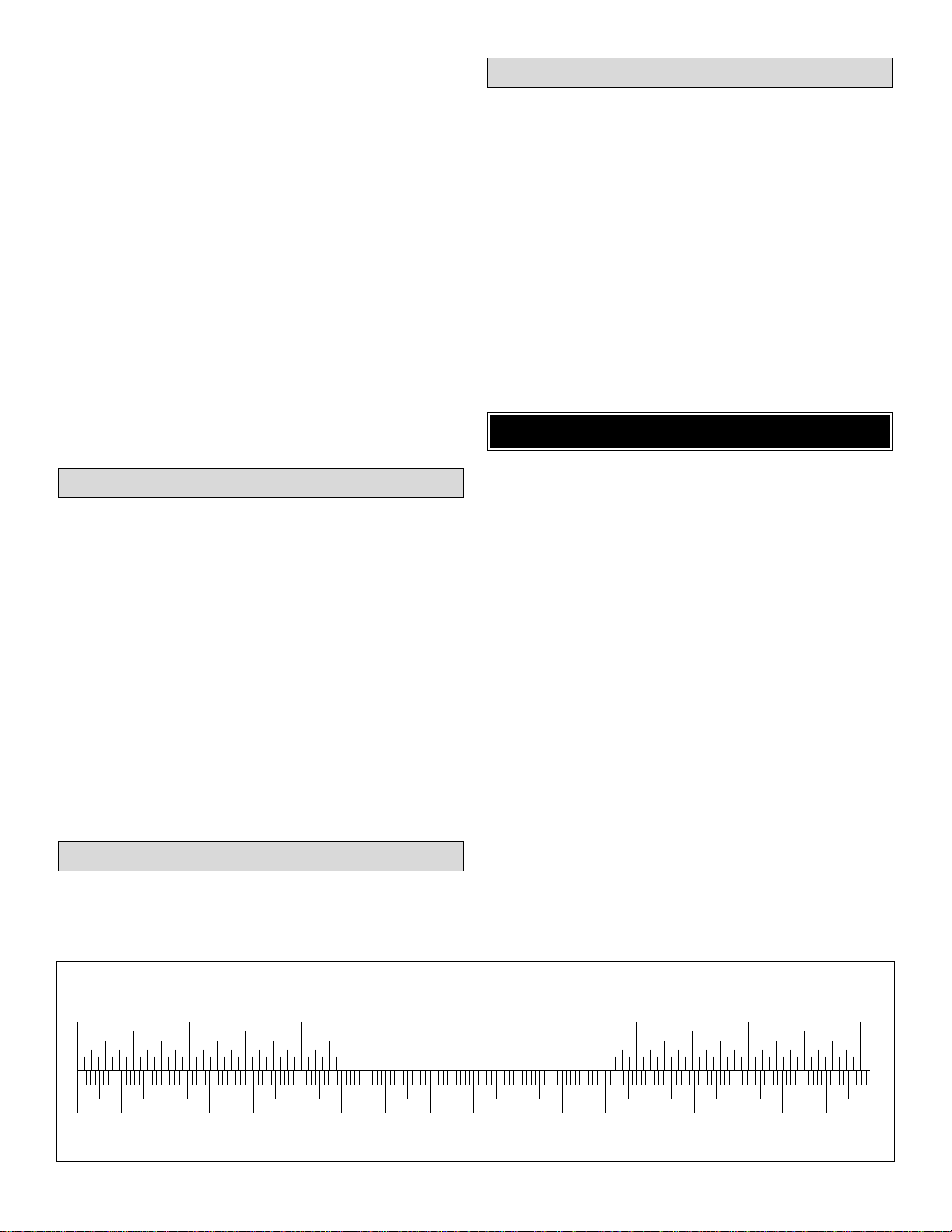
0" 1" 2" 3" 4" 5" 6" 7"
0 10 20 30 40 50 60 70 80 90 100 110 120 130 140 150 160 170 180
Inch Scale
Metric Scale
To convert inches to millimeters, multiply inches by 25.4
Charge Rate/Time Recommendations:
• Charge the 6-cell 550 mAh battery pack at 50 mAh for
11 hours.
• Charge the 7-cell 550 mAh battery pack at 50 mAh for
11 hours.
• Charge the 7-cell 1200 mAh battery pack at 100 mAh for
12 hours.
IMPORTANT: Monitor the temperature of the battery frequently.
If the battery becomes warm, disconnect it from the charger.
A Hobbico R/C Multi-Charger (HCAP0100) is suitable for
charging the battery packs used in the Park Flyers.
Note: The period required to charge the batteries in the
examples above is for discharged batteries. If the battery
you are going to charge is not discharged (and you are not
using a peak-charger), connect it to the motor on your
model. Run the motor until the propeller is turning slowly,
thus discharging the battery.
In addition to common household tools and hobby tools, this
is the “short list”of the most important items required to build
the Headwind B.Great Planes Pro™ CA and Epoxy glue are
recommended.
❏ Hook & Loop Velcro
®
(GPMQ4480)
❏ Hobby knife (HCAR0105)
❏ #11 blades (HCAR0211)
❏ Small T-pins (HCAR5100)
❏ Top Flite
®
Panel Line Pen (TOPQ2510)
❏ Electric dr ill and 1/16" [1.6mm] drill bit
❏ Small Phillips and flat blade screwdrivers
❏ Pliers with wire cutter (HCAR0630)
❏ 1/2 oz. Thin Pro
™
CA (GPMR6001)
❏ 1/2 oz. Medium Pro CA+ (GPMR6007)
❏ 6-Minute Epoxy (GPMR6045)
❏ Top Flite MonoKote
®
sealing iron (TOPR2100)
❏ Top Flite MonoKote trim seal iron (TOPR2200)
Here is a list of optional tools mentioned in the manual that
will help you build the Headwind B.
❏ Great Planes CG Machine
™
(GPMR2400)
❏ Straightedge with scale (HCAR0475)
❏ Masking T ape (TOPR8018)
❏ CA accelerator (GPMR6034)
❏ R/C-56 Canopy Glue (JOZR5007)
❏ Epoxy Brushes (GPMR8060)
❏ Mixing Sticks (GPMR8055)
❏ Denatured Alcohol (for epoxy clean up)
❏ Non-elastic monofilament or Kevlar fishing line (for
stab alignment)
❏ Builders Triangle Set (HCAR0480) (for fin alignment)
• When you see the term
test fit
in the instructions, it
means that you should first position the part on the
assembly without using any glue, then slightly modify or
custom fit
the part as necessar y for the best fit.
• Whenever the term
glue
is written you should rely upon
your experience to decide what type of glue to use.When a
specific type of adhesive works best for that step, the
instructions will make a recommendation.
• Photos and sketches are placed before the step they
refer to. Frequently you can study photos in following steps
to get another view of the same parts.
• The Headwind B is factory-covered with Top Flite
MonoKote film. Should repairs ever be required, MonoKote
can be patched with additional MonoKote purchased
separately. MonoKote is packaged in six-foot rolls, but some
hobby shops also sell it by the foot. If only a small piece of
MonoKote is needed for a minor patch, perhaps a fellow
modeler would give you some. MonoKote is applied with a
model airplane covering iron, but in an emergency a regular
iron could be used. A roll of MonoKote includes full
instructions for application. The Headwind B is covered in
Transparent Green Monokote (TOPQ0306).
IMPORTANT BUILDING NOTES
Optional Supplies and Tools
Covering Accessories
Adhesives and Building Supplies
4
Page 5
5
To order replacement parts for the Great Planes Headwind B, use the order numbers in the Replacement Parts List that
follows. Replacement parts are available only as listed. Not all parts are available separately (an aileron cannot be
purchased separately, but is only available with the wing kit).Replacement par ts are not available from Product Support,
but can be purchased from hobby shops or mail order/Internet order firms. Hardware items (screws, nuts, bolts) are also
available from these outlets. If you need assistance locating a dealer to purchase par ts, visit www.greatplanes.com and
click on “Where to Buy.” If this kit is missing parts, contact Great Planes Product Support.
Replacement Parts List
Order Number Description How to Purchase
Missing pieces ................................................Contact Product Support
Instruction manual...........................................Contact Product Support
Full-size plans.................................................Not available
Kit parts listed below .......................................Hobby Supplier
GPMA2570 ...........Fuselage Set
GPMA2572 ...........Wing Set
GPMA2574 ...........Tail Set
GPMA2576 ...........Landing Gear Set
GPMA2578 ...........Windshield
GPMA2580 ...........Hardware Pack
ORDERING REPLACEMENT PARTS
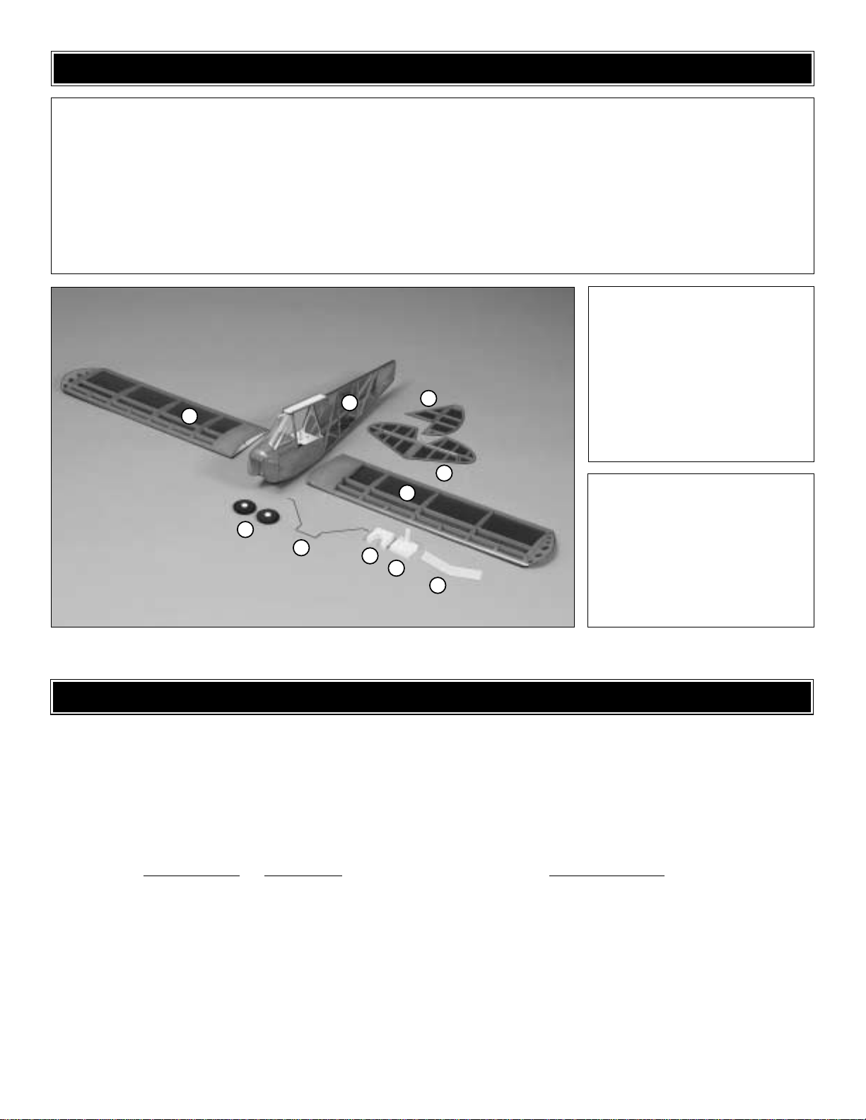
1 Fuselage (w/windshield
and outer pushrods)
2 Horizontal tail
3 Vertical tail
4 Left wing
5 Right wing
6 Wing joiner
7 GP motor mount
8 GWS motor mount
9 Main gear wire
10 Main wheels
(2) Control horns
(2) Clevises
(4) Wheel retainers
(1) Tail skid wire
(1) Balsa main gear block
(1) Plastic wing TE support
(1) Bag small rubber bands (battery)
(1) Bag large rubber bands (wing)
(2) Pushrod wires
Kit Contents (Photographed)
Kit Contents (Not Photographed)
Before starting to build, use the Kit Contents list to take an inventory of this kit to make sure it is complete and inspect
the parts to make sure they are of acceptable quality. If any parts are missing or are not of acceptable quality, or if you
need assistance with assembly, contact Great Planes Product Support. When reporting defective or missing parts, use
the part names exactly as they are written in the Kit Contents list on this page.
3002 N. Apollo Drive, Suite 1
Champaign, IL 61822
Telephone: (217) 398-8970
Fax: (217) 398-7721
E-mail: airsupport@greatplanes.com
KIT INSPECTION
5
10
9
1
7
3
2
4
8
6
Page 6

❏ 1.Test fit the wing joiner into the slots in the wing halves.
Sand the joiners as required to get a tight, secure fit that
allows the wing panels to mate as nicely as possible.NOTE:
If the root ribs’ angles aren’t exactly the same, that’s ok.The
difference can be filled with epoxy when the wings are joined.
The proper dihedral angle and the gluing of the wing joiner is
far more important than the mating of the two wing panels.
❏ 2. Cover your workbench with wax paper.
❏ 3. With the left wing flat on your workbench and the
center joint on the wax paper, raise the right wing 6-1/4"
[160mm] to properly set the dihedral. Block the raised right
wing at the desired height and make a mental note of the
position needed for it to maintain that dihedral.Slide the left
wing and joiner off the right wing.
❏ 4. Remove the joiner from the left wing. Cover the joiner,
left and right wing ribs and pockets in the wing panels with
a moderate but not excessive amount of 30-minute epoxy.
Join the wing halves together. Ensure that the left wing
remains flat and the right wing tip is 6-1/4" [160mm] from
your work bench and can remain that way undisturbed for at
least 4 hours, preferably overnight.HINT: Use masking tape
to hold the wing together while the epoxy hardens.Remove
any excess epo xy with a paper tow el and denatured alcohol,
being careful not to disturb the joint.
❏ 5. Glue the plastic TE support centered on the wing.
❏ 1. Place the fuselage upside-down on the workbench.
Drill a 1/16" [1.6mm] hole centered on and 1" [25mm] from
the end of the bottom of the fuselage.
❏ 2. Sand the area of the tail skid that contacts the fuse
with coarse sandpaper.
❏ 3. Cover the sanded area of the tail skid with epoxy and
glue the tail skid in place.
Assemble the Tail
Note: Accurate assembly of the wing is critical.In addition
to your first cursory reading, please read all steps in this
section carefully prior to beginning wing assembly.
Assemble the Wing
BUILDING INSTRUCTIONS
6
Page 7

❏ 4. Remove the covering from the control horn slot on the
left side of the rudder.
❏ 5. Glue the rudder control into the slot with medium CA.
❏ 6.The bottom of the horizontal stab has the large gap f or
the elevator hinge .Place the stab upside-down on your work
bench. Mark the inside end of the right elevator 1/4" [5mm]
that is perpendicular to the elevator’s leading edge, and that
runs from behind the leading edge to the trailing of the stab.
Carefully trim the inner edge off the elevator as shown.
❏ 7. Glue the elevator control horn in place with medium
CA. Note: The removed piece can be shaped and glued to
the other side of the control horn for appearance if you
desire, but it is not necessary.
❏ 8. Center and align the TE of the stab with the TE of the
fuse.Pin the front center of the stab to the center of the fuse.
Note: Folding the elevator up makes aligning the TEs with
each other easier.
❏ 9. Attach a string to the wing dowel and pull it back to the
left corner of the stab. Mark the string at that location on a
piece of tape.Move the end of the string to the other side of
the stab.Rotate the stab until both lengths are the same. Pin
the TE of the stab to the fuse.
7
Page 8

❏ 10. Using a felt-tip pen, mark the covering on the bottom
of the stab where it contacts the fuse. Also mark the top of
the fuse along the LE of the stab.Note: Be careful not to cut
into the balsa stab when removing the covering.
❏ 11. Remove the stab. Cut the covering from the marked
area of the stab and from the mark on the top of the fuse to
the rear of the stab saddle.
❏ 12. Mount the wing to the fuse with two long rubber
bands.Pin the stab to the fuse. Lift the stab off, and coat the
stab and fuse with epoxy. Reinstall the stab with the pin for
guidance. Checking from behind the aircraft to make sure
the stab is parallel with the wing, epoxy the stab in place.
❏ 13. Center the fin on the stab and align it with the center
of the fuse. Mark the stab on both sides of the base of the
fin. Remove the covering from the marked area of the top of
the stab and the bottom of the fin.Note: Be careful not to cut
into the balsa stab when removing the covering.
❏ 14.Glue the fin to the stab, making sure to keep it aligned
with the centerline of the fuse and perpendicular to the stab.
8
Page 9

❏ 1. Remove the tape holding the canopy to the fuse.
Cutting small amounts at a time with sharp scissors, fit the
canopy. When satisfied with the fit, glue the canopy in place
with canopy glue.
❏ 2. Push one plastic wheel collar on each axle.
❏ 3. Slide the wheels on the axles and hold them in place
with the 2 remaining wheel collars.
❏ 4. Remove the covering from the landing gear slot in the
bottom of the fuse.
❏ 5. Fit the landing gear in the fuse. Lock the gear in place
by gluing the 1/16" x 7/8" x 2" [1.6x22x50mm] balsa sheet in
the landing gear slot.
❏ 1. Bend one end of both wire pushrods to the shape
shown in the sketch.
❏ 2. Slide the straight end of the pushrods into the fuselage
through the front of the pushrod tubes.
❏ 3. Fit two servos in the fuse. Plug the ser vos into your
receiver. Tur n on the transmitter and receiver to center the
servos. Attach the pushrods to the servo arms.Making sure
not to preload the pushrods, mount the servos to the servo
tray with the hardware provided with your radio. Turn the
transmitter and receiver off.
❏ 4. Being careful not to push the pushrod tubes, glue the
balsa servo pushrod support to the former behind the servos.
Install the Servos and Pushrods
Install the Canopy and Main Gear
9
Page 10

❏ 5.Turn on the transmitter and receiver. Double-check that
the elevator trim is centered and that the ele vator is centered
to the stab.Mark the pushrod at the location that the elevator
pushrod crosses the hole in the control horn.
❏ 6. Cut the pushrod 1/2" [13mm] behind the mark on the
pushrod. Bend the pushrod 90 degrees away from the fuse.
Attach the pushrod to the middle hole of the control horn
as shown.
❏ 7. Double-check that the rudder trim is centered and that
the rudder is centered on the fin. Mark the rudder pushrod
where it crosses the control horn.
❏ 8. Cut the pushrod 1/2" [13mm] behind the mark on the
pushrod. Bend the pushrod 90 degrees towards the top of
the fuse. Attach the pushrod to the control hor n as shown.
❏ 1. Following the motor manufacturer’s instructions,
assemble your motor and gear box.
❏ 2. The front of the motor mount is plywood. Temporarily
mount the gear box to the front of the motor mount with
three #2-3/8" [10mm] screws (included with the T280GD
ESC system). Remove the gear box from the motor mount.
❏ 3. Align the top, round shape of the motor mount to the
same shape in the former at the front of the fuse.Glue in place.
❏ 4. Using the mount’s top screw hole as a guide, drill a
3/16" [4.6mm] hole through the front of the fuse.
Note: The Headwind B is easily fitted with a variety of
powerplants. We tested the model most extensively with
the Great Planes T280GD ESC system with the 4.1:1 gear
ratio, and these instructions are written to install that
power system. We found that the GWS IPS IPS-DX2BB
motor system was also a good choice, and a motor mount
for the GWS system is included. Whatever motor you
decide to use, make sure to use one of the supplied motor
mounts so that the designed 2° of right thrust is built in.
Install the Motor
10
Page 11

❏ 5. Re-mount the gear box and motor to the mount.
The battery and receiver mounting are used to adjust the
center of gravity (CG).We recommend using the Great Planes
Sanyo®8 Cell 350 2/3AA NiCd to power your Headwind B.For
now, temporarily position the battery and receiver in the radio
compartment as shown, but do not secure in place. When
setting the CG (below), adjust positioning as needed,
remembering to also reposition the Velcro®and rubber band
mounting to properly hold them in place.
❏ 1. Turn on the transmitter and receiver and center the
trims. If necessary, remove the servo arms from the servos
and reposition them so they are centered. Reinstall the
screws that hold on the servo arms.
❏ 2. With the transmitter and receiver still on, check all the
control surfaces to see if they are centered. If necessary,
adjust the pushrods to center the control surfaces.
❏ 3. Make certain that the control surfaces respond in the
correct direction as shown in the diagram. If any of the
controls respond in the wrong direction, use the servo
reversing in the transmitter to reverse the ser vos connected
to those controls. Be certain the control surfaces have
remained centered. Adjust if necessary.
Use a Great Planes AccuThrow™(or a ruler) to accurately
measure and set the control throw of each control surface as
indicated in the chart that follows. NOTE: The throws are
measured at the widest part of the elevator and rudder.
These are the recommended control surface throws:
ELEVATOR: 1/2" [13mm] up
1/2" [13mm] down
RUDDER: 1" [25mm] right
1" [25mm] left
IMPORTANT: The Headwind B has been extensively
flown and tested to arrive at the throws at which it flies
best. Flying your model at these throws will provide you
with the greatest chance for successful first flights.If, after
you have become accustomed to the w ay the Headwind B
flies, you would like to change the throws to suit your
taste, that is fine. However, too much control throw could
make the model difficult to control, so remember, “more is
not always better.”
Set the Control Throws
4-CHANNEL
TRANSMITTER
TRANSMITTER
4-CHANNEL
TRANSMITTER
4-CHANNEL
ELEVATOR MOVES UP
RUDDER MOVES RIGHT
MOTOR TURNS
3-CHANNEL RADIO SETUP
(STANDARD MODE 2)
Check the Control Directions
GET THE MODEL READY TO FLY
Complete Final Radio Installation
11
Page 12

At this stage the model should be in ready-to-fly condition
with all of the systems in place including the motor, landing
gear, and the radio system.
❏ 1.Use a felt-tip pen or 1/8"-wide [3mm] tape to accurately
mark the C.G.on the bottom of the wing on both sides of the
fuselage. The C.G. is located 1-3/4" [45mm] back from
the leading edge of the wing.
❏ 2. With the wing attached to the fuselage, and all parts of
the model installed (ready to fly), place the model right-sideup on a Great Planes CG Machine, or lift it right-side-up at
the balance point you marked.
❏ 3. If the tail drops, the model is “tail heavy”and the battery
pack and/or receiver must be shifted forward or weight must
be added to the nose to balance.If the nose drops, the model
is “nose heavy”and the battery pack and/or receiver must be
shifted aft or weight must be added to the tail to balance. If
possible, relocate the battery pack and receiver to minimize
or eliminate any additional ballast required. If additional
weight is required, use Great Planes (GPMQ4485) “stick on”
lead. A good place to add stick-on nose weight is to the
firewall. Begin by placing incrementally increasing amounts
of weight on the bottom of the fuse over the firewall until the
model balances. Once you have determined the amount of
weight required, it can be permanently attached. If required,
tail weight may be added by cutting open the bottom of the
fuse and gluing it permanently inside.
Note: Do not rely upon the adhesive on the back of the lead
weight to permanently hold it in place. Over time, various
factors could cause the weight to f all off.Use #2 sheet metal
screws, RTV silicone or epoxy to permanently hold the
weight in place.
❏ 4. IMPORTANT: If you found it necessary to add any
weight, recheck the C.G.after the weight has been installed.
❏ 1. With the wing level, have an assistant help you lift the
model by the motor propeller shaft and the bottom of the
fuse under the TE of the fin.Do this several times.
❏2.If one wing always drops when you lift the model, it means
that side is heavy. Balance the airplane by adding weight to the
other wing tip. An airplane that has been laterally balanced
will track better in loops and other maneuvers.
No matter if you fly at an AMA sanctioned R/C club site or if
you fly somewhere on your own, you should always have
your name, address, telephone number and AMA number
on or inside your model. It is required at all AMA R/C club
flying sites and AMA sanctioned flying events.
Follow the battery charging instructions that came with your
radio control system to charge the batteries.You should always
charge your transmitter batteries the night before you go flying,
and at other times as recommended by the radio manuf acturer .
Charge the Batteries
Identify Y our Model
PREFLIGHT
Balance the Model Laterally
This is where your model should balance for your first
flights. Later, you may wish to experiment by shifting the
C.G. through a range of 1-1/2" [38mm] to 2" [51mm] to
change the flying characteristics. Moving the C.G. forward
may improve the smoothness and stability, but it may then
require more speed for takeoff and mak e it more difficult to
slow for landing. Moving the C.G. aft makes the model
more maneuverable , b ut could also cause it to become too
difficult for you to control.In any case. start at the location
we recommend and do not at any time balance your model
outside the recommended range.
More than any other factor, the C.G. (balance point) can
have the greatest effect on how a model flies, and may
determine whether or not your first flight will be
successful. If you value this model and wish to enjoy it for
many flights, DO NOT OVERLOOK THIS IMPORTANT
PROCEDURE. A model that is not proper ly balanced will
be unstable and possibly unflyable.
Balance the Model (C.G)
12
1-3/4" 1-3/4"
Page 13

NOTE: Checking the condition of the battery pack before
EVERY flight, even if just off the charger, is highly
recommended. All battery packs, whether it’s a trusty pack
you’ve just taken out of another model, or a new battery
pack you just purchased, should be cycled, noting the
discharge capacity. Oftentimes, a weak battery pack can be
identified (and a valuable model saved!) by comparing its
actual capacity to its rated capacity. Refer to the instructions
and recommendations that come with your cycler. If you
don’t own a battery cycler, perhaps you can have a friend
cycle your pack and note the capacity for you.
Carefully balance your propeller and spare propellers before
you fly. An unbalanced prop can be the single most
significant cause of vibration that can damage your model.
For electric motors, proper balance is even more critical than
glow motors. Not only will motor mounting screws and bolts
loosen, possibly with disastrous effect, b ut vibration ma y also
damage your radio receiver.
We use a Top Flite Precision Magnetic Prop Balancer
™
(TOPQ5700) in the workshop and keep a Great Planes
Fingertip Prop Balancer (GPMQ5000) in our flight box.
If the motor is new, follow the motor manufacturer’s
instructions to break-in the motor.After you run the motor
on the model, inspect the model closely to make sure all
screws remained tight, the prop is secure and all pushrods
are secure.
Ground check the operational range of your r adio before the
first flight of the day. With the transmitter antenna collapsed
and the receiver and transmitter on, you should be able to
walk at least 100 feet away from the model and still have
control. Have an assistant stand by your model and, while
you work the controls, tell you what the control surfaces are
doing. Repeat this test with the motor running at various
speeds with an assistant holding the model, using hand
signals to show you what is happening. If the control
surfaces do not respond correctly, do not fly! Find and
correct the problem first.Look for loose servo connections or
broken wires, corroded wires on old servo connectors, poor
solder joints in your battery pack or a defective cell, or a
damaged receiver crystal from a previous crash.
• Get help from an experienced pilot when learning to
operate motors.
• Use safety glasses when starting or running motors.
• Do not run the motor in an area of loose gravel or sand;
the propeller may throw such material in your f ace or ey es.
• Keep your face and body as well as all spectators away
from the plane of rotation of the propeller at all times that
the motor is armed.
• Keep these items away from the prop: loose clothing,
shirt sleeves, ties, scarfs, long hair or loose objects such
as pencils or screwdrivers that may fall out of shirt or
jacket pockets into the prop.
• REMEMBER! This is an electric motor. Unlike a glow
motor,it can start at any time without any mo vement
of the prop by the user. ALWAYS take extreme care
around your electric motor.
• Make all motor adjustments from behind the rotating
propeller.
• The motor gets hot! So does the battery pack and ESC.
Do not touch it during or right after operation.
• Do not use hands, fingers or any other body part to try to
stop the motor. Do not throw anything into the propeller
of a running motor.
Read and abide by the following Academy of Model
Aeronautics Official Safety Code:
1. I will not fly my model aircraft in sanctioned events, air
shows, or model flying demonstrations until it has been
proven to be airworthy by having been previously
successfully flight tested.
General
AMA SAFETY CODE (
EXCERPT
)
Failure to follow these safety precautions may result
in severe injury to yourself and others.
MOTOR SAFETY PRECAUTIONS
Range Check
Ground Check
Balance Propellers
13
Page 14

2. I will not fly my model aircraft higher than approximately
400 feet within 3 miles of an airport without notifying the
airpor t operator. I will give right of way to, and avoid flying in
the proximity of full scale aircraft. Where necessary an
observer shall be used to supervise flying to avoid having
models fly in the proximity of full scale aircraft.
3. Where established, I will abide by the safety rules for the
flying site I use, and I will not willfully and deliberately fly my
models in a careless, reckless and/or dangerous manner.
7. I will not fly my model unless it is identified with my
name and address or AMA number, on or in the model.
9. I will not operate models with pyrotechnics (any device
that explodes, burns, or propels a projectile of any kind).
1. I will have completed a successful radio equipment
ground check before the first flight of a new or repaired
model.
2. I will not fly my model aircraft in the presence of
spectators until I become a qualified flier, unless assisted b y
an experienced helper.
3. I will perform my initial turn after takeoff away from the
pit or spectator areas, and I will not thereafter fly over pit or
spectator areas, unless beyond my control.
4. I will operate my model using only radio control frequencies
currently allowed by the F ederal Communications Commission.
❏ 1. Check for proper saf ety operation of y our speed control.
❏ 2. Check the C.G. according to the measurements
provided in the manual.
❏ 3. Be certain the battery and receiver are securely
mounted in the fuse. Simply stuffing them into place with
foam rubber is not sufficient.
❏ 4. Extend your receiver antenna and make sure it has a
strain relief inside the fuselage to keep tension off the solder
joint inside the receiver.
❏ 5. Balance your model laterally as explained in
the instructions.
❏ 6. Use threadlocking compound to secure critical
fasteners such as the screws that hold the motor, etc.
❏ 7. Add a drop of oil to the axles so the wheels will turn freely.
❏ 8. Make sure all surfaces are held securely in place.
❏ 9. Reinforce holes for wood screws with thin CA
where appropriate (servo mounting screws, cowl mounting
screws, etc.).
❏ 10. Confirm that all controls operate in the correct
direction and the throws are set up according to the manual.
❏ 11. Make sure that all servo arms are secured to the
servos with the screws included with your radio.
❏ 12. Secure the connection between your battery pack
and the on/off switch with vinyl tape, heat shrink tubing or
special clips suitable for that purpose.
❏ 13. Make sure any servo extension cords you may have
used do not interfere with other systems (servo arms,
pushrods, etc.).
❏ 14. Use an incidence meter to check the wing for twists
and attempt to correct before flying.
❏ 15. Balance your propeller (and spare propellers).
❏ 16. Tighten the propeller nut.
❏ 17. Place your name, address, AMA number and
telephone number on or inside your model.
❏ 18. If you wish to photograph your model, do so before
your first flight.
❏ 19. Range check your radio when you get to the flying field.
The Headwind B is a great-flying model that flies smoothly
and predictably. It possesses most of the self-recovery
characteristics of a primary R/C trainer, but still should be
flown only with the assistance of experienced R/C pilots.
FLYING
During the last few moments of preparation your mind
may be elsewhere anticipating the excitement of the first
flight. Because of this, you may be more likely to overlook
certain checks and procedures that should be performed
before the model is flown.To help avoid this, a checklist is
provided to make sure these important areas are not
overlooked. Many are covered in the instruction manual,
so where appropriate, refer to the manual for complete
instructions. Be sure to check the items as off they are
completed (that’s why it’s called a
check list
!).
CHECKLIST
Radio Control
14
Page 15

Before you get ready to takeoff, see how the model handles
on the ground by doing a few practice runs at low speeds on
the runway.If you need to calm your nerves before the maiden
flight, shut the motor down and bring the model back into the
pits.Top off the batter y with a quick peak charge, then check
all fasteners and control linkages for peace of mind.
For your first few flights, it is a good idea to hand launch the
model to retain as much power as possible for flight.
ALWAYS have an experienced modeler who knows how to
propel a model straight ahead complete the first tosses.
If you decide to do rolling take offs, then remember to tak eoff
into the wind. When you’re ready, point the model straight
down the runway, then gradually advance the throttle. Gain
as much speed as your runway and flying site will practically
allow before gently applying up ele v ator, lifting the model into
the air. At this moment it is likely that you will need to apply
more right rudder to counteract motor torque. Be smooth on
the elevator stick, allowing the model to establish a gentle
climb to a safe altitude before turning into the traffic pattern.
For reassurance and to keep an eye on other traffic, it is a
good idea to have an assistant on the flight line with you.Tell
him to remind you to throttle back once the plane gets to a
comfortable altitude.While full throttle is usually desirable for
takeoff, most models fly more smoothly at reduced speeds.
Take it easy with the Headwind B for the first few flights,
gradually getting acquainted with it as you gain confidence.
Adjust the trims to maintain straight and level flight. After
flying around for a while, and while still at a saf e altitude with
plenty of battery power still left, practice slow flight and
execute pr actice landing approaches by reducing the throttle
to see how the model handles at slower speeds.Add power
to see how she climbs as well. Continue to fly around,
executing various maneuvers and making mental notes (or
having your assistant write them down) of what trim or C.G.
changes may be required to fine tune the model so it flies
the way you lik e.Mind your power response, but use this first
flight to become familiar with your model before landing.
To initiate a landing approach, lower the throttle while on the
downwind leg. Allow the nose of the model to pitch downward
to gradually bleed off altitude. Continue to lose altitude, but
maintain airspeed by keeping the nose down as you turn onto
the crosswind leg.Make your final turn toward the runway (into
the wind) keeping the nose down to maintain airspeed and
control.Level the attitude when the model reaches the runway
threshold, modulating the throttle as necessary to maintain
your glide path and airspeed. If you are going to overshoot,
smoothly advance the throttle (always ready on the right
rudder to counteract torque) and climb out to make another
attempt.When you’re ready to make y our landing flare and the
model is a foot or so off the deck, smoothly increase up
elevator until it gently touches do wn.Once the model is on the
runway and has lost flying speed, hold up elev ator to place the
tail on the ground, regaining tail wheel control.
One final note about flying your model. Have a goal or flight
plan in mind for every flight. This can be learning a new
maneuver(s), improving a maneuver(s) you already know, or
learning how the model behaves in certain conditions (such as
on high or low rates). This is not necessarily to improve your
skills (
though it is never a bad idea!
), but more importantly so
you do not surprise yourself by impulsively attempting a
maneuver and suddenly finding that you’ve run out of time,
altitude or airspeed.Every maneuver should be deliberate, not
impulsive.For example, if you’re going to do a loop, check your
altitude, mind the wind direction (anticipating rudder
corrections that will be required to maintain heading),
remember to throttle back at the top, and mak e certain you are
on the desired rates (high/low rates). A flight plan greatly
reduces the chances of crashing your model just because of
poor planning and impulsive moves. Remember to think.
Have a ball! But always stay in control
and fly in a safe manner.
GOOD LUCK AND GREAT FLYING!
Landing
Flight
Takeoff
CAUTION (THIS APPLIES TO ALL R/C AIRPLANES): If,
while flying, you notice any unusual sounds, such as a
low-pitched “buzz,” this may indicate control surface
flutter
. Because flutter can quickly destroy components of
your airplane, any time you detect flutter you must
immediately cut the throttle and land the airplane! Check
all servo grommets for deterioration (this may indicate
which surface fluttered), and make sure all pushrod
linkages are secure and free of play. If the control surface
fluttered once, it probably will flutter again under similar
circumstances unless you can eliminate the free-play or
flexing in the linkages. Here are some things which can
cause flutter: Excessive hinge gap; Not mounting control
horns solidly; Poor fit of clevis pin in horn; Side-play of
pushrod in guide tube caused by tight bends;Poor fit of Zbend in servo arm; Insufficient glue used when gluing in
the elevator joiner wire; Excessive
play
or
backlash
in
servo gears; and Insecure servo mounting.
15
Page 16

Great Planes®ElectriFly™Peak Charger
Peak charging convenience
for Park Flyers!
Great for economy, ease and efficiency, the 3FR offers a
whole new angle on park flyer systems. Elevator and aileron
(or rudder) control is centered on a single stick, the same way
it is on 4-channel systems.Learn on the 3FR today and you’re
acquiring skills for future flights, too. Case design supports
correct thumb placement with an “S”curve on the right, while
a thumb recess on the left provides a better grip.A slide switch
offers easy, proportional control of throttle, flap or spoiler.The
on-board package includes an R114F receiver, two S3106
micro servos and a 250mAh NiCd for the receiver. There’s
also a 600mAh NiCd for the transmitter and an AC charger
that can recharge both at once! 1-year warranty.Note: Should
not be used on low-band channels 11-15. (FUTJ52**)
Futaba
®
3FR FM Radio
ACCESSORIES AVAILABLE FROM GREAT PLANES
Single-stick simplicity,
FM clarity and NiCd
convenience, all in one!
Receiver:
R114F
Servos:
S3106 (2)
Tx NiCd:
600mAh
Rx NiCd:
250mAh
Band:
72MHz
Worried about receiver-transmitter compatibility? Hook up
an economical ElectriFly 4-Channel Mini FM receiver and it
will automatically select the circuitry compatible with your
Futaba
®
, JR®, Hitec®, or Airtronics®“Z” radios. Innovative
circuitry makes them a match for most popular systems–
their size, weight (just 10g!) and range* make them perfect
for the Y ard Stik and other small electrics.Designed for park,
slow and indoor flyers, Mini FM Receivers feature SMT
components for maximum dependability in an ultralight,
compact unit. Available in high- and low-band versions on
72MHz. Require a short, single-conversion Futaba FM
crystal, available separately. 1-year warranty.
*Note: ElectriFly Receivers are suitable for use with Park
Flyers and other aircraft that require a ground reception
range of 900 feet (max.).
Great Planes®ElectriFly™Mini FM Receivers
Designed for small, lightweight electrics and transmitter
batteries, this charger can also be used with any 6 8 cell
NiCd or NiMH pack.It plugs into a power supply or cigarette
lighter for fast charges. Pulsed current charging protects
small packs from overheating. Charge rate adjusts to 200
mAh or 600mAh. A 15mA trickle charge keeps packs
topped off for use anytime. Includes 2-pin connector for
ElectriFly packs; adapters available separately. 1-year
warranty.
(GPMM3000)
GPML0044 Low Band
GPML0045 High Band
 Loading...