

Page 1
WARRANTY
Great Planes
®
Model Manufacturing Co. guarantees this kit to be free from defects in both material and workmanship at the date of
purchase.This warranty does not cover any component parts damaged by use or modification. In no case shall Great Planes’ liability
exceed the original cost of the purchased kit. Further, Great Planes reserves the right to change or modify this warranty without notice.
In that Great Planes has no control over the final assembly or material used for final assembly, no liability shall be assumed nor
accepted for any damage resulting from the use by the user of the final user-assemb led product.By the act of using the user-assembled
product, the user accepts all resulting liability.
If the buyer is not prepared to accept the liability associated with the use of this product, the buyer is advised to return this
kit immediately in new and unused condition to the place of purchase.
READ THROUGH THIS MANUAL BEFORE
STARTING CONSTRUCTION. IT CONTAINS
IMPORTANT WARNINGS AND INSTRUCTIONS
CONCERNING THE ASSEMBLY AND USE OF
THIS MODEL.
GPMZ0209 for GPMA1100 V1.1© Copyright 2003, Printed in China
Champaign, Illinois
(217) 398-8970, Ext 5
airsupport@greatplanes.com
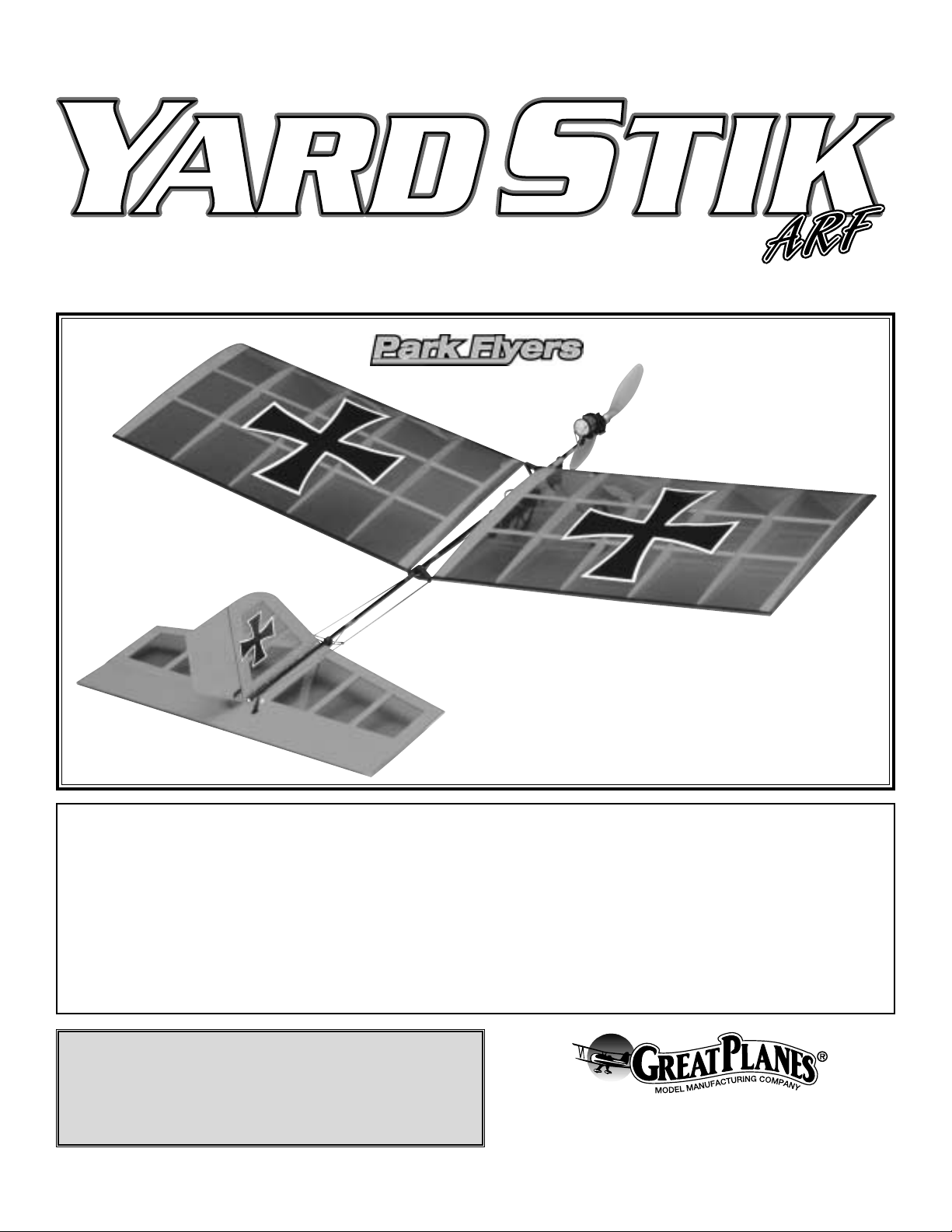
INSTRUCTION MANUAL
Wingspan: 41 in [1040mm]
Wing Area: 496 sq in [32 dm2]
Weight: 12 oz [340 g]
Wing Loading: 3 oz/sq ft [9 g/dm2]
Length: 38.5 in [980mm]
Radio: 3-channel w/2 micro servos,
micro receiver and electronic speed control
TM
Page 2
INTRODUCTION ...............................................................2
SAFETY PRECAUTIONS..................................................2
DECISIONS YOU MUST MAKE........................................3
Radio Equipment ...............................................................3
Speed Controller................................................................3
Battery ...............................................................................4
Charger..............................................................................4
ADDITIONAL ITEMS REQUIRED.....................................4
Building Supplies ...............................................................4
Optional Items....................................................................4
ORDERING REPLACEMENT PARTS ..............................4
KIT CONTENTS ................................................................5
ASSEMBLY .......................................................................6
Assemble the Tail...............................................................6
Mount the Fuselage Parts .................................................7
Mount the Motor.................................................................9
FINAL SET UP................................................................10
Set Up the Radio .............................................................10
Set the Control Throws....................................................11
Apply the Decals ..............................................................12
Mount the Wings and Check the C.G..............................12
CHECKLIST ....................................................................13
PREFLIGHT.....................................................................13
Identify the Model ............................................................13
Charge the Batteries ........................................................14
Range Check...................................................................14
PERFORMANCE TIPS....................................................14
Balance the Propeller ......................................................14
Cycle the Batteries...........................................................14
MOTOR SAFETY PRECAUTIONS .................................14
AMA SAFETY CODE......................................................15
FIND A SAFE PLACE TO FLY........................................15
FLYING ............................................................................15
Congratulations and thank you for purchasing the Great
Planes Y ard Stik. Since park flyers are small and fly slowly,
little space is required. In fact, the Yard Stik can be flown
both indoors and outdoors. Park flyers are also perfect for
those evenings at the field when everybody else is packing
up their gear, the wind has died and there is still enough light
to fly a small, slow model that can be kept close-in.
The Yard Stik is a slow flying model that is about as simpleto-build as they get.However , if you ha v e ne v er flown an R/C
model before, learning to fly the Yard Stik all by yourself is
not recommended. As with any trainer airplane, you should
find an experienced modeler to help you with your first
flights. Information about R/C clubs and instructors is
provided later in this manual.
Attention: The product you have purchased is
powered by a rechargeable battery. At the end of its useful
life, under various state and local laws, it may be illegal to
dispose of this battery into the municipal waste system.
Check with your local solid waste officials for details in your
area for recycling options or proper disposal.
This product contains a chemical known to the state of
California to cause cancer and birth defects or other
reproductive harm.
1. Even though the Yard Stik is small, lightweight and
flies slowly, if it is not assembled and operated correctly it
could possibly cause injury to yourself or spectators and
damage property.
2. Build the plane according to the instructions. Do not
alter or modify the model, as doing so may result in an
unsafe or unflyable model.
3. Use an R/C radio system that is in first-class condition.
This Park Flyer requires micro servos, a micro receiver and
a micro speed control able to handle 5 amps.
4. You must properly install all R/C and other components so
that the model operates properly on the ground and in the air.
5. You must test the operation of the model before every
flight to insure that all equipment is operating and that the
model has remained structurally sound. Be sure to check
connectors often and replace them if they show signs of
wear or fatigue.
PRO TECT YOUR MODEL,YOURSELF
& OTHERS...FOLLOW THESE
IMPORTANT SAFETY PRECAUTIONS
CAUTION: Be aware that the Yard Stik is operated on the
same frequency band as larger, “regular” R/C models. If
flying your Yard Stik within five miles of an R/C site, there
is a real possibility that you could be operating your model
on the same frequency (channel) as another R/C pilot. If
this happens, a crash will result–with the person flying the
more expensive model suffering the greater loss (and
having greater potential for property damage or injury).
The best way to avoid this is to join an R/C club and fly
at the site where frequency control measures will be in
effect. If you do insist on flying elsewhere, always be
aware of your proximity to R/C flying sites.
INTRODUCTION
TABLE OF CONTENTS
2
Page 3
Remember:Take your time and follow directions to end
up with a well-built model that is straight and true.
If you’re an inexperienced modeler, we recommend that you
get assistance from an experienced, knowledgeable
modeler to help you with assembly and your first flights.
You’ll learn faster and avoid risking your model bef ore y ou’re
truly ready to solo. Your local hobby shop has information
about flying clubs in your area whose membership includes
qualified instructors.
You can also contact the national Academy of Model
Aeronautics (AMA), which has more than 2,500 chartered
clubs across the country. Through any one of them,
instructor training programs and insured newcomer training
are available. Contact the AMA at the address or toll-free
phone number below:
Academy of Model Aeronautics
5151 East Memorial Drive
Muncie, IN 47302-9252
Tele. (800) 435-9262
Fax (765) 741-0057
Or via the Internet at:
http://www.modelaircraft.org
Please inspect all parts carefully before starting to
build. If any parts are missing, broken or defective, or if
you have any questions about building or flying this
airplane, please give us a call at (217) 398-8970 or e-mail
us at productsupport@greatplanes.com and we’ll be
glad to help. If you are calling for replacement parts,
please reference the part numbers and have them ready
when calling.
Following is a list of items required to finish the Yard Stik that
must be purchased separately. For some of these items
there is more than one option which will require a bit of
decision making ahead of time. Order numbers (in
parentheses) are provided for your convenience.
The Yard Stik requires a micro receiver and two micro
servos. If you already have a transmitter you are going to
use to fly the Yard Stik, you can get the receiver and servos
separately. Or, you can purchase a complete system
(including transmitter) specially packaged for park flyers. If
purchasing a complete system, the Futaba®3FR
Skysport
single-stick radio is suitable. It comes with a micro receiver
and two Futaba S-3106 micro servos. The transmitter also
has NiCd’s.Following are descriptions and part numbers for
suitable radio equipment.
• Futaba 3FR Skysport single-stick radio system including
transmitter, receiver and servos (FUTJ52**)
– OR –
• Futaba R114F 4-channel low band FM micro receiver
w/o crystal (FUTL0442)
• Futaba low band receiver crystal for R114F receiver
(FUTL62**)
– OR –
• Futaba R114F 4-channel high band FM micro receiver
w/o crystal (FUTL0443)
• Futaba high band receiver crystal R114F receiver
(FUTL63**)
– OR –
• Great Planes ElectriFly™4-channel FM low band mini
receiver w/o crystal (shown in this manual) (GPML0044)
• Great Planes ElectriFly 4-channel FM high band mini
receiver w/o crystal (shown in this manual) (GPML0045)
– AND –
• Futaba S3103 Micro-Mini servo (FUTM0037)
• Futaba S3106 Micro-Mini servo (FUTM0041)
• Hobbico®CS-5 Nano™servo (HCAM0090)
Note: When purchasing radio sets or receiver crystals,
replace the “**” at the end of the par t number (FUTL62**)
with the desired channel number. Low band receivers must
use low band crystals and high band receivers must use
high band receivers. Channels 11 through 35 are in the low
band and channels 36 through 60 are in the high band.The
Great Planes ElectriFly 4-channel receivers use the same
crystals listed for the Futaba receivers. Be certain to select
a high band or low band crystal to match the receiver.
An electronic speed control with BEC (Battery Eliminator
Circuitry) is required. The BEC allows both the motor and
the radio system to be powered by the same battery (thus
eliminating the on-board receiver battery).The Great Planes
ElectriFly C-5
Nano
High Frequency Electronic Speed
Control (GPMM2000) is recommended.
Speed Control
Radio Equipment
DECISIONS YOU MUST MAKE
Note: We, as the kit manufacturer, provide you with a top
quality kit and great instructions, but ultimately the quality
and flyability of your finished model depends on how you
build it; therefore, we cannot in any way guarantee the
performance of your completed model and no
representations are expressed or implied as to the
performance or safety of your completed model.
3
Page 4
The Great Planes 7.2v 650 mAh NiMH (nickel-metal h ydride)
battery (GPMP0068) is recommended. It is the correct size
and shape to fit in the battery holder on the Yard Stik.
The best type of charger to use is a peak charger, because
it charges the batteries until they are fully charged, then
automatically switches to a trickle charge mode.The Great
Planes ElectriFly Peak Charger (GPMM3000) is suitable for
charging the nickel-metal hydride battery recommended for
the Yard Stik.
To figure out how long it will take to charge the battery , divide
its capacity (in mAh) by the charge rate being used. If fully
discharged, the 650 mAh battery recommended for the Yard
Stik, charged at a rate of 600 mAh (by the ElectriFly Peak
Charger), will take about 65 minutes to charge (650 divided
by 600 times 60 minutes = 65).Note: It is not recommended
to charge the battery at a rate any higher than two times its
rated capacity.
IMPORTANT: Monitor the temperature of the battery frequently.
If the battery becomes warm, disconnect it from the charger.
In addition to the items previously discussed and common
building supplies and hobby tools, following is a list of the
items required to assemble the Yard Stik.
Great Planes
Pro™CA is recommended.
❏ 1/2" [13mm] double-sided foam tape (GPMQ4440)
❏ 1/2 oz. [15g] Thin Pro CA (GPMR6001)
❏ 1/2 oz. [15g] Medium Pro CA+ (GPMR6007)
❏ #1 Hobby knife (HCAR0105)
❏ #11 blades (5-pack, HCAR0211)
❏ medium-grit sandpaper
❏ Propeller balancer (TOPQ5700) (Balancing propellers
on Park Flyers is important as it will increase efficiency
and improve performance and extend run time.)
❏ CA applicator tips (HCAR3780)
❏ Single-edge razor blade
❏ 2 oz. [57g] spray CA activator (GPMR6035)
❏ APC 11 x 4.7 Slo-Flyer propeller for more performance
outdoors (APCQ5020)
❏ APC 9 x 4.7 Slo-Flyer propeller for better indoor flying
(APCQ5010)
Optional Items
Building Supplies
ADDITIONAL ITEMS REQUIRED
Charger
Battery
4
To order replacement parts for the Yard Stik, use the order numbers in the Replacement Parts List that follows.
Replacement parts are available only as listed.Not all parts are available separately. Replacement parts are not available
from Product Support, but can be purchased from hobby shops or mail order/Internet order firms. If you need assistance
locating a dealer to purchase parts, visit www.greatplanes.com and click on “Where to Buy.” If this kit is missing par ts,
contact Great Planes Product Support.
Replacement Parts List
Order Number Description How to Purchase
Missing pieces ................................................Contact Product Support
Instruction manual...........................................Contact Product Support
Full-size plans.................................................Not available
Kit parts listed below .......................................Hobby Supplier
GPMA2434 ...........Wing Set
GPMA2435 ...........Fuselage Boom
GPMA2436 ...........Tail Set
GPMA2437 ...........Plastic Set
GPMA2438 ...........Landing Gear
GPMA2439 ...........Decal
GPMQ1650 ...........10 x 4.7 Propeller
ORDERING REPLACEMENT PARTS
Page 5
5
0" 1" 2" 3" 4" 5" 6" 7"
0 10 20 30 40 50 60 70 80 90 100 110 120 130 140 150 160 170 180
Inch Scale
Metric Scale
To convert inches to millimeters, multiply inches by 25.4
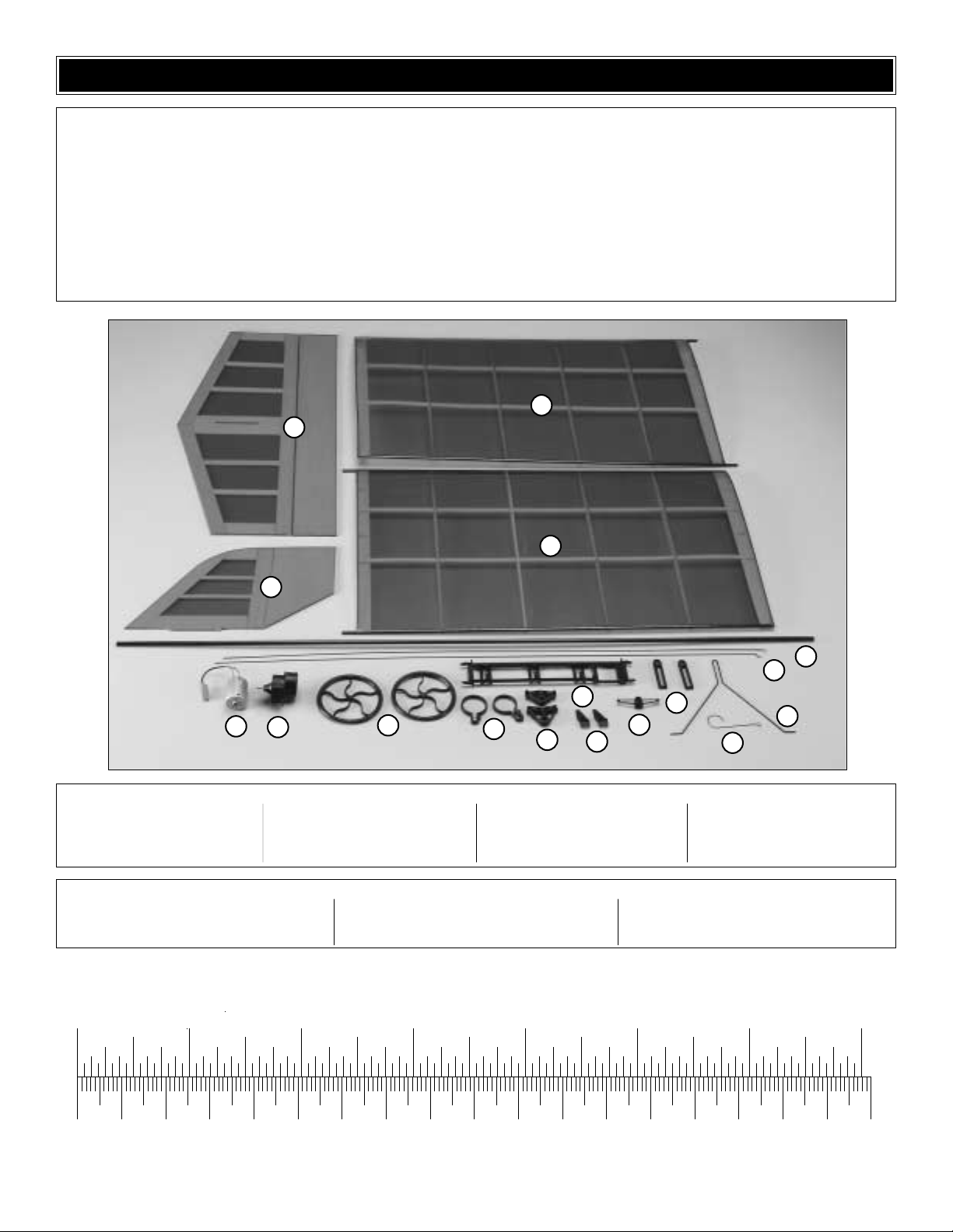
1 Wings
2 Stabilizer w/Elevator
3 Fin w/Rudder
4 Motor
5 Gearbox
6 Wheels
7 Motor Mounting Straps (F & R)
8 Wing Mounts
9 Control Horns
10 Tail Wire Mount
11 Main Landing Gear Wire
12 Tail Wire
13 Battery Holder Mounts
14 Battery Holder
15 Pushrod Wires
16 Fuselage Boom
Pinion Gear
Gear Cement
Prop Adapter
Propeller
(2) Control Horn Retainers
(2) Pushrod Retainers
(2) #2 x 1/2" Screws
(2) Wheel Retainers
Decal Sheet
Kit Contents (Photographed)
Kit Contents (Not Photographed)
Before starting to build, use the Kit Contents list to take an inventory of this kit to make sure it is complete and inspect
the parts to make sure they are of acceptable quality. If any parts are missing or are not of acceptable quality, or if you
need assistance with assembly, contact Great Planes Product Support. When reporting defective or missing parts, use
the part names exactly as they are written in the Kit Contents list on this page.
3002 N. Apollo Drive, Suite 1
Champaign, IL 61822
Telephone: (217) 398-8970
Fax: (217) 398-7721
E-mail: airsupport@greatplanes.com
KIT INSPECTION
1
2
1
3
14
4
5
6
7
8
9
13
10
12
16
15
11
Page 6

❏ 1. Use a straightedge and a single-edge razor blade or a
#11 hobby blade to cut the covering from the left side of the
fin across the top of the tab as shown in the photo.Use a light
touch to cut only into the covering and not into the wood.
Also be sure to use a new blade–if the blade is dull it will
cause you to apply more pressure, thus cutting into the wood.
❏ 2. Use the same technique to cut the covering from the
right side of the fin as shown.
❏ 3.Cut the covering from the top of the stabilizer the same
way. Note: The top of the stabilizer has the slot for the fin
offset to the left.
❏ 4. Cut a narrow slot in the elev ator to accommodate one of
the control horns 15/16" [24mm] from the edge of the slot in
the stab and 3/16" [5mm] from the leading edge of the elevator .
❏ 5. Fit the control horn into the slot in the top of the
elevator. Add a few drops of thin CA to the bottom of the
elevator where the tab comes out of the slot. Install the
retainer, followed by another drop or two of thin CA.
❏ 6. Cut a slot and mount the control horn to the left side
of the rudder the same way.The slot should be 3/4" [19mm]
from the bottom of the rudder and 3/16" [5mm] from the
leading edge of the rudder.
Assemble the Tail
ASSEMBLY
6
Page 7

❏ 7. Use medium CA to glue the rudder to the stab. Use a
small builder’ s square to make certain the fin is perpendicular
to the stabilizer.
❏ 1. Identify the molded plastic mounting parts and lay
them out on your workbench as shown in the photo. The
front of all the par ts is facing upward.
❏ 2. Note that the front of the boom is the end with the wood
plug. Slip the fuselage parts onto the boom in the order that
they are laid out in the photo.Arrange the par ts so the front
battery holder mount is 3-1/2" [90mm] from the front of the
boom (as shown in the photo at step 5) and the front wing
mount is approximately 7" [180mm] from the front of the
boom. The rear wing mount should be approximately 19"
[480mm] from the front of the boom.The exact location of the
wing mounts will be determined later when balancing the
model and the tail wire mount will be positioned when the
pushrod wires are installed.
❏ 3. Use medium CA to glue the fuselage boom to the
stabilizer and fin.
❏ 4. Fit the main landing gear wire onto the front of the
battery holder. Then, mount the battery holder to the
battery holder mounts previously installed on the fuselage.
❏ 5. Position the battery holder and battery holder mounts
so the front battery holder is 3-1/2" [90mm] from the front of
the fuselage boom.Make sure the battery holder and battery
holder mounts are vertical.Then, use a few drops of thin CA
to permanently glue the mounts to the fuselage boom.
Mount the Fuselage Parts
7
Page 8

❏ 6.Mount the servos to the battery holder as shown using
the screws and rubber grommets that came with the servos.
❏ 7. Make an approximately 1/2" [13mm] deep V-bend in
both pushrod wires as shown (the precise location and
depth of the bends isn’t critical).Guide the pushrods through
the tail wire mount and the aft wing mount. Then, if
necessary, slightly enlarge the holes in the servo arms to
accommodate the wires and mount the wires to the servo
arms. Note: The elevator pushrod (on the right side of the
model–not visible in the photograph) goes in the servo arm
on the top of the ser vo.
❏ 8.Center the servo arms on the servos.Make an L-bend
in the end of both wires where they fit into the control horns
so the rudder and elevator will be centered. Cut off any
excess wire so approximately 1/4" [6mm] of the “L” remains.
Connect the pushrods to the second-from-the-outer holes in
the control horns. Later, after the elevator and rudder have
been centered and the control throws have been set,
retainers will be installed on the wires so they cannot come
out of the control horns.
❏ 9. Fit the tail wire into the slot in the bottom of the tail
wire mount. Use a few drops of thin CA followed by a few
drops of medium CA to glue the tail wire into the mount and
to glue the mount onto the fuselage boom.
❏ 10. Use medium-grit sandpaper to roughen the ends of the
landing gear wire where the retainers go.Slip on the wheels,
and then glue on the retainers with a drop of medium CA. Be
careful not to inadvertently get any glue on the wheels.
❏ 11. Bend the tail wire as necessary to raise the elevator
approximately 1/2" [13mm] from the ground when it is level.
8
Page 9

❏ 1. Without using any tools, use your fingers to press the
motor all the way into the gearbox. Spin the shaft on the
gearbox.If the shaft does not spin freely, back the motor out
just enough to allow the shaft to spin freely. Use a fine-point
felt-tip pen to mark the end of the gearbox onto the motor so
you will know how far to reinstall the motor after the pinion
gear has been fitted.
❏ 2. Remove the motor from the gearbox.
❏ 3. Use denatured alcohol or other solvent to clean the
motor shaft. Roughen the shaft with medium-gr it sandpaper
so the included gear cement will adhere.
❏ 4. Test fit the pinion gear onto the motor shaft to see
which way it goes on easiest.The hole in the pinion gear is
tapered slightly and the “easy way” is the way the gear is to
be permanently installed.
❏ 5. Remove the pinion gear from the motor. Add a small
drop of gear cement to the hole in the end of the gear that
goes on the shaft.Install the gear until the end is even with the
end of the shaft.Allow the cement to harden for a f ew minutes .
❏ 6. Use a toothpick to apply a small dab of lubricating oil
to both ends of the motor shaft where it exits the motor. Do
not apply oil directly from the container because you may
apply too much.
❏ 7. Reinstall the motor into the gearbox up to the line.Fit the
prop adapter to the gearbox. Mount the prop to the adapter
using the appropriate spacer ring and the prop washer and
prop nut. Tighten the prop nut with an 8mm wrench. If
necessary , protecting the drive w asher with a cloth, use pliers
to hold the drive washer while tightening the nut.
❏ 8. Spin the propeller by hand.The magnets in the motor
should provide slight resistance. If more resistance can be
felt than just the motor, back the motor out of the gearbox
slightly until the propeller turns as it should.
Mount the Motor
9
Page 10

❏ 9. Mount the motor to the fuselage with the front and
rear mounting straps and two #2 x 1/2" [13mm] screws
(the larger strap goes in front). The straps should also be
arranged so the screws go in from the left side. Tighten the
screws enough to secure the motor, but do not strip out the
plastic. When viewing the motor from above, the motor
should be centered on the fuselage.
It will be a little easier to set up the radio
before mounting the wings.
❏ 1. Determine how the receiver and speed controller will
be positioned. Make sure all the wires will reach their
connections. Mount the speed controller to the receiver and
mount the receiver to the battery holder using double-sided
foam mounting tape. Connect all the wires. Use the black
strips provided on the decal sheet to tape the receiver
antenna to a few locations along the fuselage boom. Hint:
Use small pieces of fuel tubing (not supplied) to neatly hold
the servo wires together.
❏ 2. For safety, remove the propeller from the motor.This
will prevent potential injury in case the motor unexpectedly
turns on while setting up the radio.
Caution: Do not connect the motor wire to the speed
controller unless flying the model or setting up the radio on
the workbench. Otherwise, the motor could unintentionally
and unexpectedly turn on.
Set Up the Radio
FINAL SET UP
10
Page 11

❏ 3.If you haven’t already done so , plug the receiver crystal
into the receiver. Be cer tain the crystal matches the band
(high or low) for the receiver you are using.
❏ 4. Make certain the throttle control on the transmitter is all
the way down.Connect the servos and speed controller to the
receiver .Turn on the transmitter, and then connect the battery
to the receiver .Center the trims on the transmitter.If the servo
arms aren’t already centered, take the arms off the servos
and center the arms. Remount the arms with the screws.
❏ 5. If necessary, use pliers to open or close the V-bends
in the pushrods to get the rudder and elevator centered.
❏ 6. Use the control sticks on the transmitter to operate the
elevator and rudder. Make certain they respond in the
correct direction. If they do not, use the servo reversing
switches in the transmitter to change the direction.
❏ 7. Reminder: The propeller should be removed from the
motor while performing setup operations in the shop.Follow
the instructions included with whatever speed controller you
have selected to turn on the motor .If necessary, reverse the
throttle servo reversing switch to get the motor to turn on
when the throttle is advanced.
❏ 1. Use the transmitter to move the elev ator all the way up
and down and measure the distance the trailing edge moves
(throw). The distance should be 3/4" [19mm] up and 3/4"
[19mm] down. If necessary, move the elevator pushrod to
another hole in the control horn to change the throw.Moving
IMPORTANT: Do not overlook this important procedure.
The control throws have a great effect on how a model
flies and may determine whether or not your first flight is
a success.
Set the Control Throws
4-CHANNEL
TRANSMITTER
TRANSMITTER
4-CHANNEL
TRANSMITTER
4-CHANNEL
ELEVATOR MOVES UP
RUDDER MOVES RIGHT
MOTOR TURNS
3-CHANNEL RADIO SETUP
(STANDARD MODE 2)
11
Page 12

the pushrod to a hole closer in (to the elevator) will increase
the throw. Moving the pushrod to a hole farther out will
decrease the throw. Moving the pushrod on the servo arms
has the opposite effect.
❏ 2. Set the rudder control throw the same way. Rudder
throw should be 1" [25mm] right and 1" [25mm] left.
❏ 3. After the control throws have been set, use medium-
grit sandpaper to thoroughly roughen the ends of the
pushrods where they go through the control horns. Add a
pushrod retainer to each control rod and secure with a
drop of medium CA.
Use scissors or a sharp hobby knife to cut out the decals.
You can apply the decals dry, or spray the surface where the
decal is to be applied with window cleaner.Then, apply the
decal and squeegee out the cleaner with a soft sheet of
balsa.This will remove air bubbles from under the decals for
the best appearance.
❏ 1. Use narrow strips of tape to mar k the C.G. (center of
gravity) on the bottom of both wings 3-7/8" [98mm] from the
leading edge of the wing.
❏ 2. Mount the wings to the fuselage boom by fitting them
into the wing mounts.
❏ 3. If you haven’t done so already, mount the propeller to
the motor. At this stage the model should be in ready-to-fly
condition with all of the components installed, including the
wheels, battery, receiver, speed controller, etc.
IMPORTANT: Do not overlook this important procedure.
Failure to balance the model at the specified C.G. (center
of gravity) may result in an unflyable model.
Mount the Wings and Check the C.G.
Apply the Decals
12
Page 13

❏ 4. Lift the model with your finger tips placed on the tape
lines.If the model is level as shown in the photo the wing is in
the correct position. Proceed to the next step. If the nose of
the model drops, the C.G.is too far forward and the wing will
have to be moved forward. If the tail of the model drops, the
C.G.is too far back and the wing must be moved back. Move
the wing forward or back as necessary by sliding the wing
mounts.Continue to adjust the position of the wing and lift the
model with your fingers on the tape lines until you can get it to
balance. Note: Even though the decals are not on the model
in the photo, they should be on your model at this time.
❏ 5. View the model from the rear. Using the stab as an
alignment cue, make sure both wings are at the same angle
when compared to the stab. If necessary, adjust the wing
mounts to get both wings the same.
❏ 6. Once you have achieved the correct C.G.and leveled
the wings, use a few drops of thin CA to permanently glue
the wing mounts to the fuselage boom.
Before taking your Yard Stik out to the flying field for the first
time (or to your back yard or the park), review the check list
to make sure it is truly ready to fly.
❏ 1. Make sure all the controls move in the correct direction.
❏ 2. Be sure the control throws match the measurements
provided.
❏ 3. Make sure the elevator and rudder are centered by
adjusting the V-bends in the pushrods.
❏4. Make sure the model balances at the recommended C.G.
❏ 5. Check the servo arms to make sure the servo arm
screws are installed.
❏ 6. Make sure the pushrod retainers are on the back of the
pushrods on the control horns.
No matter if you fly at an AMA sanctioned R/C club site or if
you fly somewhere on your own, you should always have
your name, address, telephone number and AMA number
on or inside your model. It is required at all AMA R/C club
flying sites and AMA sanctioned flying events. Fill out the
identification tag on the decal sheet and place it on the
bottom of the wing.
Identify Y our Model
PREFLIGHT
CHECKLIST
13
Page 14

Follow the battery charging instructions that came with your
radio control system to charge the batteries in the
transmitter.You should always charge the batteries the night
before you go flying and at other times as recommended by
the radio manufacturer.
Ground check the operational range of your radio before the
first flight of the day. With the transmitter antenna collapsed
and the receiver and transmitter on, you should be able to
walk at least 100 feet away from the model and still have
control.Have an assistant stand by y our model and, while you
work the controls, tell you what the control surfaces are doing.
IMPORTANT! Repeat this test with the motor running at
various speeds with an assistant holding the model, using
hand signals to show you what is happening. If the control
surfaces do not respond correctly, do not fly! Find and
correct the problem first. Look for loose servo connections or
broken wires, corroded wires on old servo connectors, or a
damaged receiver crystal from a previous crash.
Use fine sandpaper to remove imperf ections along the edges
of the propeller. Carefully balance the propeller and spare
propellers before flying.A balanced propeller on a lightweight
model such as this will improve efficiency and extend run
time and improve performance. A high-performance,
sensitive prop balancer such as the Top Flite®Precision
Magnetic Prop Balancer™(TOPQ5700) is recommended.
For optimum battery performance the battery should be
cycled occasionally. “Cycling” means to fully charge (“peak”
charge) the battery, then to discharge it. Many battery
chargers have peak charging and automatic discharging
capabilities. If you do not have a charger that is able to
discharge batteries, you can discharge the battery yourself
by running the motor with the propeller attached until the
propeller barely continues to turn. Be sure to allow the
battery to cool before recharging.
Note: Failure to follow these safety precautions may result
in severe injury to yourself and others.
• Get help from an experienced pilot when learning to
operate motors.
• Use safety glasses when running motors.
• Do not run the motor in an area of loose gravel or sand;
the propeller may throw such material in your f ace or ey es.
• Keep your f ace and body as well as all spectators awa y from
the path of the propeller as you start and run the motor.
• Keep items such as these away from the prop: loose
clothing, shirt sleeves, ties, scarfs, long hair or loose
objects (pencils, screw drivers) that may fall out of shirt
or jacket pockets into the prop.
• The electric motor and motor battery used in the Yard Stik
are very powerful. The spinning propeller has a lot of
momentum; therefore, if you touch the propeller while it is
spinning it may inflict sev ere injury. Respect the motor and
propeller for the damage it is capable of and tak e whatev er
precautions are necessary to avoid injury. Always
disconnect the battery until you are ready to fly again.
• Using multiple battery packs for successive flights may
cause the motor to become excessively hot, thus
causing damage. Allow the motor to cool for at least 10
minutes between flights.
MOTOR SAFETY PRECAUTIONS
Cycle the Batteries
Balance the Propeller
PERFORMANCE TIPS
Range Check
Charge the Batteries
14
Page 15

Read and abide by the following Academy of Model
Aeronautics Official Safety Code:
1. I will not fly my model aircraft in competition or in the
presence of spectators until it has been proven to be
airworthy by having been pre viously successfully flight tested.
2. I will not fly my model aircraft higher than approximately
400 feet within 3 miles of an airport without notifying the
airpor t operator. I will give right of way to and avoid flying in
the proximity of full scale aircraft. Where necessary an
observer shall be utilized to supervise flying to avoid having
models fly in the proximity of full scale aircraft.
3. Where established, I will abide by the safety rules for the
flying site I use and I will not willfully and deliberately fly my
models in a careless, reckless and/or dangerous manner.
7. I will not fly my model unless it is identified with my name
and address or AMA number, on or in the model.
1.I will have completed a successful radio equipment ground
check before the first flight of a new or repaired model.
2. I will not fly my model aircraft in the presence of
spectators until I become a qualified flyer , unless assisted by
an experienced helper.
3.I will perform my initial turn after takeoff away from the pit,
spectator and parking areas and I will not thereafter perform
maneuvers, flights of any sort or landing approaches over a
pit, spectator or parking area.
4. I will operate my model using only radio control frequencies
currently allowed by the F ederal Communications Commission.
Though the Yard Stik is a “Park Flyer,” the best place to fly
any model is at an AMA chartered club field. Club fields are
set up for R/C flying, making your outing safer and more
enjoyab le .We recommend that you join the AMA and a local
club so you can have a safe place to fly and have insurance
to cover you in case of a flying accident.The AMA address
and telephone number are in the front of this manual.
If there is no club or R/C flying field in your area, find a
suitable site that is clear of trees, telephone poles, buildings,
towers, busy streets and other obstacles. Since you are not
flying at a sanctioned AMA site, be aware that there may be
others like yourself who could be flying nearby.If both of your
models happen to be on the same frequency, interference
will likely cause one or both of the models to crash. An
acceptable minimum distance between flying models is five
miles, so keep this in mind when searching for a flying site.
In addition to obstacles, it is important to be aware of people
who may wander into the area once you begin flying.At AMA
club flying sites it is a severe rule infraction to fly over others
and this is a good practice if flying elsewhere. R/C models
tend to attract onlookers who may pose two main problems;
First is the danger of actually crashing your model into a
person, causing injury. Second is the distraction by those
who ask you questions while you are trying to concentrate on
flying. To minimize or avoid this problem, have an assistant
standing by who can spot people who wander into your flying
site (so you can avoid flying o v er them) and who can perform
“crowd control” if people start to gather.
IMPORTANT: If you are an inexperienced modeler we strongly
urge you to seek the assistance of a competent, experienced
R/C pilot to check your model for airworthiness AND to teach
you how to fly. No matter how stable or “forgiving”the Y ard Stik
is, attempting to learn to fly on your own is dangerous and may
result in destruction of your model or even injury to yourself and
others.Therefore, find an instructor and fly only under his or her
guidance and supervision until you have acquired the skills
necessary for safe and fully controlled operation of your model.
The Yard Stik may be hand launched or it can R.O.G. (rise
off ground).It is best to hand launch the Yard Stik for the first
flight and if flying over rough fields outdoors. The model
should be tossed directly into the wind in a controlled
manner with the wings level and the fuselage in a level or
slightly nose-high attitude. Apply full power, then launch the
model.Allow the Yard Stik to settle into a gentle climb as you
turn it away from the pits or spectators.
Adjust the trims to get the model to fly straight and level.
When at a comfortable altitude reduce power and see how
the model handles.This will be a reference as to how it will
land if the battery quits.
It is best to allow the model to build up speed before
performing tight turns or other aerobatic maneuvers.Continue
to fly around until you are ready to land or until there is not
enough power to keep the model airborne. Just the same as
taking off, alwa ys land into the wind.Choose your landing spot
and then make the landing flair by gently applying full up
elevator when the Yard Stik is about 6" to 1' off the ground.
Retrieve the model and make a post-flight inspection,
looking for loose connections or fasteners. Allow the batter y
and motor to cool before recharging.
Best of luck and happy flying!
FLYING
FIND A SAFE PLACE TO FLY
Radio Control
General
AMA SAFETY CODE (
EXCERPTS
)
15
Page 16

Great Planes®ElectriFly™Peak Charger
Peak charging convenience
for Park Flyers!
Great for economy, ease and efficiency, the 3FR offers a
whole new angle on park flyer systems. Elevator and aileron
(or rudder) control is centered on a single stick, the same way
it is on 4-channel systems.Learn on the 3FR today and you’re
acquiring skills for future flights, too. Case design supports
correct thumb placement with an “S”curve on the right, while
a thumb recess on the left provides a better grip.A slide switch
offers easy, proportional control of throttle, flap or spoiler.The
on-board package includes an R114F receiver, two S3106
micro servos and a 250mAh NiCd for the receiver. There’s
also a 600mAh NiCd for the transmitter and an AC charger
that can recharge both at once! 1-year warranty.Note: Should
not be used on low-band channels 11-15. (FUTJ52**)
Futaba
®
3FR FM Radio
ACCESSORIES AVAILABLE FROM GREAT PLANES
Single-stick simplicity,
FM clarity and NiCd
convenience, all in one!
Receiver:
R114F
Servos:
S3106 (2)
Tx NiCd:
600mAh
Rx NiCd:
250mAh
Band:
72MHz
Worried about receiver-transmitter compatibility? Hook up
an economical ElectriFly 4-Channel Mini FM receiver and it
will automatically select the circuitry compatible with your
Futaba
®
, JR®, Hitec®, or Airtronics®“Z” radios. Innovative
circuitry makes them a match for most popular systems–
their size, weight (just 10g!) and range* make them perfect
for the Y ard Stik and other small electrics.Designed for park,
slow and indoor flyers, Mini FM Receivers feature SMT
components for maximum dependability in an ultralight,
compact unit. Available in high- and low-band versions on
72MHz. Require a short, single-conversion Futaba FM
crystal, available separately. 1-year warranty.
*Note: ElectriFly Receivers are suitable for use with Park
Flyers and other aircraft that require a ground reception
range of 900 feet (max.).
Great Planes®ElectriFly™Mini FM Receivers
Designed for small, lightweight electrics and transmitter
batteries, this charger can also be used with any 6 8 cell
NiCd or NiMH pack.It plugs into a power supply or cigarette
lighter for fast charges. Pulsed current charging protects
small packs from overheating. Charge rate adjusts to 200
mAh or 600mAh. A 15mA trickle charge keeps packs
topped off for use anytime. Includes 2-pin connector for
ElectriFly packs; adapters available separately. 1-year
warranty.
(GPMM3000)
GPML0044 Low Band
GPML0045 High Band
Among the special
requirements of park flyers
such as the Yard Stik is an on-board
receiver/motor battery that adds little
weight and needs minimal space -- but doesn’t
skimp on power. Designed by ElectriFly specifically
for such applications, this rechargeable 6-cell, 7.2V,
nickel-metal hydride pack measures less than 5.5" long and
only 0.75" wide... but offers 650mAh of capacity to bring out
the best in your model! (GPMP0068)
Great Planes
®
ElectriFly
™
650mAh NiMH
Battery Pack
 Loading...