

Page 1
WARRANTY
Great Planes®Model Manufacturing Co.
guarantees this kit to be free from defects in both material and workmanship at the date of purchase. This
warranty does not cover any component parts damaged by use or modification. In no case shall Great Planes’ liability exceed the original cost of the
purchased kit. Further, Great Planes reserves the right to change or modify this warranty without notice.
In that Great Planes has no control over the final assembly or material used for final assembly, no liability shall be assumed nor accepted for any
damage resulting from the use by the user of the final user-assembled product. By the act of using the user-assembled product, the user accepts all
resulting liability.
If the buyer is not prepared to accept the liability associated with the use of this product, the buyer is advised to return this kit immediately
in new and unused condition to the place of purchase.
To make a warranty claim send the defective Hobby Services
part or item to Hobby Services at this address: 3002 N. Apollo Dr., Suite 1
Champaign IL 61822
USA
Include a letter stating your name, return shipping address, as much contact information as possible (da ytime telephone number, fax number, e-mail address),
a detailed description of the problem and a photocopy of the purchase receipt.Upon receipt of the package the problem will be ev aluated as quickly as possible .
READ THROUGH THIS MANUAL BEFORE STARTING
CONSTRUCTION.IT CONTAINS IMPORTANT INSTRUCTIONS
AND WARNINGS CONCERNING THE ASSEMBLY AND
USE OF THIS MODEL.
GPMZ0191 for GPMA1070 V1.0Entire Contents © Copyright 2005
Champaign, IL
(217) 398-8970, Ext. 5
airsupport@greatplanes.com
INSTRUCTION MANUAL
™
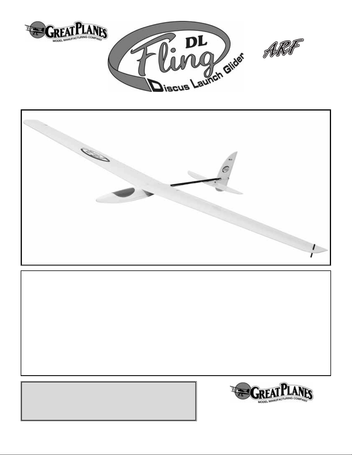
Wing Span: 60 in [1524mm]
Wing Area: 340 sq inches [22dm2]
Weight: 12 to 14 oz [340-400g]
Wing loading: 5.1-5.9 oz/sq ft [16-18g/dm2]
Fuse Length: 39-1/2 in [1000mm]
Page 2
INTRODUCTION................................................................2
AMA ...................................................................................2
SAFETY PRECAUTIONS..................................................3
DECISIONS YOU MUST MAKE ........................................3
Radio Equipment............................................................3
ADDITIONAL ITEMS REQUIRED.....................................3
Adhesives & Building Supplies.......................................3
IMPORTANT BUILDING NOTES.......................................4
ORDERING REPLACEMENT PARTS...............................4
KIT CONTENTS .................................................................5
Parts Photographed .......................................................5
Parts Not Photographed.................................................5
ASSEMBLE THE WING.....................................................6
Install the Aileron Servos ...............................................6
Join the Wing..................................................................7
ASSEMBLE THE FUSELAGE...........................................7
Canopy Removal............................................................7
Attach the Tail .................................................................8
Install Rudder and Elevator Servos................................9
FINAL INSTALLATION AND C.G. ...................................11
Install the Throwing Peg...............................................11
Set the CG ...................................................................11
Apply the Decals..........................................................11
GET THE MODEL READY TO FLY ................................11
Check the Control Directions .......................................11
Set the Control Throws.................................................12
Balance the Model Laterally.........................................12
PREFLIGHT.....................................................................12
Identify Your Model.......................................................12
Charge the Batteries....................................................12
Range Check................................................................12
AMA SAFETY CODE ......................................................13
General.........................................................................13
Radio Control ...............................................................13
CHECK LIST ....................................................................13
FLYING.............................................................................14
Launching.....................................................................14
THERMAL FLYING..........................................................15
Facts About Ther mals ..................................................15
Thermal Soaring...........................................................15
Slope Soaring...............................................................16
Slope Landings ............................................................16
The Fling DL
™
ARF is a great way to have fun and try your
hand at Discuss Launched flight. This style of launching is
easy to learn and allows launches into thermals even if the
thermal is right above you. The Fling DL has few parts
enabling easy and quick assembly and will get you to the
flying field fast. Items required for assembly are micro or
nano servos, a micro receiver and a micro Rx battery pack.
The specific recommended radio gear is listed in the
“Radio Equipment” section of the manual. Have a friend
get a Fling DL ARF too, and you can have “first up / last
down”contests or compete against each other trying to land
the Fling DL ARF closest to a certain place...a spot landing!
Have fun with your new Fling DL ARF!
For the latest technical updates or manual corrections to the
Fling DL ARF visit the Great Planes web site at
www.greatplanes.com. Open the “Airplanes” link, then
select the Fling DL ARF.If there is new technical information
or changes to this model a “tech notice” box will appear in
the upper left corner of the page.
We urge you to join the AMA (Academy of Model
Aeronautics) and a local R/C club. The AMA is the
governing body of model aviation and membership is
required to fly at AMA clubs. Though joining the AMA
provides many benefits, one of the primary reasons to join
is liability protection. Coverage is not limited to flying at
contests or on the club field. It even applies to flying at
public demonstrations and air shows.Failure to comply with
the Safety Code (excerpts printed in the back of the
manual) may endanger insurance coverage. Additionally,
training programs and instructors are available at AMA club
sites to help you get started the right way. There are over
2,500 AMA chartered clubs across the countr y.Contact the
AMA at the address or toll-free phone number below:
Academy of Model Aeronautics
5151 East Memorial Drive
Muncie, IN 47302
Tele: (800) 435-9262
Fax (765) 741-0057
Or via the Internet at:
http://www.modelaircraft.org
AMA
INTRODUCTIONTABLE OF CONTENTS
2
Page 3
IMPORTANT!!! Two of the most impor tant things you can
do to preserve the radio-controlled aircraft hobby are to
avoid flying near full-scale aircraft and avoid flying near or
over groups of people.
1. Your Fling DL ARF should not be considered a toy, but
rather a sophisticated, working model that functions very
much like a full-size airplane. Because of its performance
capabilities, the Fling DL ARF, if not assembled and
operated correctly, could possibly cause injury to yourself or
spectators and damage to property.
2. You must assemble the model according to the
instructions. Do not alter or modify the model, as doing so
may result in an unsafe or unflyable model. In a few cases
the instructions may differ slightly from the photos.In those
instances the written instructions should be considered
as correct.
3.You must take time to build straight, true and strong.
4. You must correctly install all R/C and other components
so that the model operates correctly on the ground and in
the air.
5.You must check the operation of the model before every
flight to insure that all equipment is operating and that the
model has remained structurally sound. Be sure to check
clevises or other connectors often and replace them if they
show any signs of wear or fatigue.
6. If you are not an experienced pilot or have not flown this
type of model before, we recommend that you get the
assistance of an experienced pilot in your R/C club for your
first flights.If you’re not a member of a club, y our local hobby
shop has information about clubs in your area whose
membership includes experienced pilots.
Remember:Take your time and follow the instructions to
end up with a well-built model that is straight and true.
This is a partial list of items required to finish the Fling DL ARF
that may require planning or decision making before starting to
build.Order numbers are provided in parentheses.
❏ 4 channel radio
❏ Y-harness (HCAM2500) or two 12” [300mm]
extensions (HCAM2100) utilizing a radio with
flaperon mixing
❏ Great Planes ElectriFly
™
4-channel mini receiver w/o
crystal (GPML0044 for low band, GPML0045 for
high band)
❏ Low band receiver crystal for Great Planes mini
receivers (channels 11 to 35, FUTL62**)
❏ High band receiver crystal for Great Planes mini
receivers (channels 36 to 60, FUTL63**)
❏ (4) Futaba
®
S3108 micro servos (FUTM0042)
❏ Great Planes 4.8V 350 mAh NiMH receiver battery
(GPMP0950)
In addition to common household tools and hobby tools, this
is the “short list” of the most important items required to
build the Fling DL ARF. Great Planes Pro™ CA and Epoxy
glue are recommended.
❏ 1/4” [6mm] R/C foam rubber – (HCAQ1000)
❏ 1/2 oz. [15g] Thin Pro CA (GPMR6001)
❏ Pro 30-minute epoxy (GPMR6047)
❏ Plan Protector (GPMR6167) or wax paper
❏ #1 Hobby knife (HCAR0105)
❏ #11 Blades (5-pack, HCAR0211)
❏ 2 oz. [57g] Spray CA activator (GPMR6035)
❏ Mixing cups (GPMR8056)
❏ Epoxy brushes (6, GPMR8060)
❏ Builder’s Tr iangle Set (HCAR0480)
Adhesives & Building Supplies
ADDITIONAL ITEMS REQUIRED
Radio Equipment
DECISIONS YOU MUST MAKE
We, as the kit manufacturer, provide you with a top
quality, thoroughly tested kit and instructions, but
ultimately the quality and flyability of your finished model
depends on how you build it;therefore, we cannot in any
way guarantee the performance of your completed
model, and no representations are expressed or implied
as to the performance or safety of your completed model.
PRO TECT YOUR MODEL,Y OURSELF
& OTHERS...FOLLOW THESE
IMPORTANT SAFETY PRECAUTIONS
3
Page 4
· Whenever the term
glue
is written you should rely upon your experience to decide what type of glue to use.When a
specific type of adhesive works best for that step, the instructions will make a recommendation.
· Whenever just
epoxy
is specified you may use
either
30-minute (or 45-minute) epoxy or6-minute epoxy. When
30-minute epoxy is specified it is highly recommended that you use only 30-minute (or 45-minute) epoxy, because you will
need the working time and/or the additional strength.
· Photos and sketches are placed before the step they refer to.Frequently you can study photos in follo wing steps to get
another view of the same parts.
To convert inches to millimeters, multiply inches by 25.4 (25.4mm = 1”)
IMPORTANT BUILDING NOTES
4
Replacement parts for the Great Planes Fling DL ARF are available using the order numbers in the Replacement Parts
List that follows.The fastest, most economical service can be provided by your hobby dealer or mail-order company.
To locate a hobby dealer, visit the Hobbico web site at www.hobbico.com. Choose “Where to Buy” at the bottom of the
menu on the left side of the page.Follow the instructions provided on the page to locate a U.S., Canadian or International
dealer. If a hobby shop is not available, replacement parts may also be ordered from Tower Hobbies at
www.towerhobbies.com, or by calling toll free (800) 637-6050.
Parts may also be ordered directly from Hobby Services by calling (217) 398-0007, or via facsimile at (217) 398-7721, but
full retail prices and shipping and handling charges will apply.Illinois and Nevada residents will also be charged sales tax.
If ordering via fax, include a Visa®or MasterCard®number and expiration date for payment.
Mail parts orders and payments by personal check to: Hobby Services
3002 N Apollo Drive, Suite 1
Champaign IL 61822
Be certain to specify the order number exactly as listed in the Replacement Parts List. Payment by credit card or
personal check only; no C.O.D.
If additional assistance is required for any reason contact Product Support by e-mail at productsupport@greatplanes.com,
or by telephone at (217) 398-8970.
ORDERING REPLACEMENT PARTS
Order Number Description How to purchase
GPMA2709 ....................Wing Set........................Contact your local hobby supplier
GPMA2708 ....................Fuselage ........................Contact your local hobby supplier
GPMA2710 ....................Tail Set...........................Contact your local hobby supplier
GPMA2711 ....................Hardware Set ................Contact your local hobby supplier
GPMA2712 ....................Canopy..........................Contact your local hobby supplier
GPMA2713 ....................Decal Set.......................Contact your local hobby supplier
Missing pieces...............Contact Product Suppor t
Instruction manual.........Contact Product Support
Full-size plans ...............Not available
Page 5
5
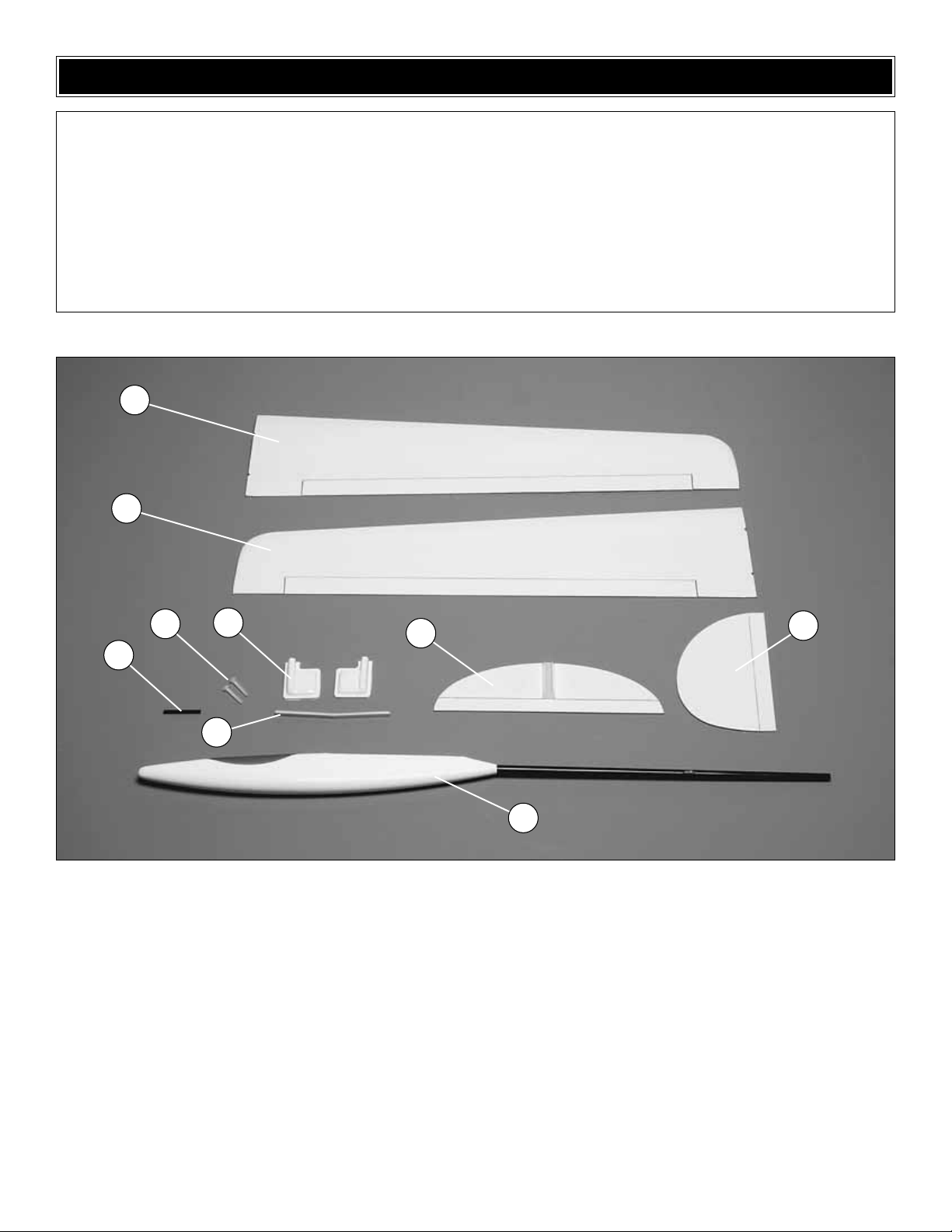
Parts Photographed
1. Right wing and aileron
2. Left wing and aileron
3. Carbon throwing peg
4. 8-32 nylon wing bolts
5. Aileron ser vo hatches
6.Wing joiner
7. Hor izontal stab and elevator
8.Vertical fin and rudder
9. Fuselage and canopy
Parts Not Photographed
1. Plywood aileron and elevator
control horns (3)
2. Plywood rudder control hor n
3. 6” [152mm] Aileron pushrods
4. Bag of steel shot
5. 39” [1meter] thin wire
6. Spool of pull/pull str ing
7.Plastic pull/pull elevator turnaround
8. Decal sheet
Before starting to build, take an inventory of this kit to make sure it is complete, and inspect the parts to make sure they
are of acceptable quality. If any parts are missing or are not of acceptable quality, or if you need assistance with assembly,
contact Product Support.When reporting defective or missing parts, use the part names exactly as they are written in the
Kit Contents list.
Great Planes Product Support
3002 N Apollo Drive, Suite 1
Champaign, IL 61822
Telephone: (217) 398-8970, ext. 5
Fax: (217) 398-7721
E-mail: airsupport@greatplanes.com
KIT CONTENTS
Kit Contents
1
2
3
4
5
6
7
8
9
Page 6

❏ ❏ 1. Cut a 3/16" x 1/2" [4.8 x 13mm] slot in the bottom
of the wing centered with the aft end of the hole in the root
rib and 3/16" [4.8mm] from the wing center.
❏ ❏ 2. Slide the aileron servo lead through the wing and
out the hole you just made.
❏ ❏ 3. Plug the servos and battery into your receiver.Turn
on the transmitter to center the servos.
❏ ❏ 4. Make a one-sided servo arm and position it on the
servo as shown in the picture. Make sure that the arm is
centered with the radio on and the trim centered.
❏ ❏ 5.Clean the side of the servo with alcohol.Lightly coat the
inside of the servo opening with medium CA.Press the servo into
the center of the servo opening. Use the pushrod and servo
cover to position the servo.
NOTE:If the CA is not spread thin enough it might wick into the
servo and cause the gears to bind. Do Not Use Thin CA!
❏ ❏ 6. From the 1/16" x 6" [1.6mm x 150mm] pushrod
make a pushrod with Z bends on each end that goes from
the servo arm to the center of the hinge line.
❏ ❏ 7. Cut the covering from the control horn slot on the
bottom of the aileron. Fit the plywood control horn to the
pushrod. Fit the control horn in the slot. Make sure that the
arm is centered with the radio on and the trim centered.
Align the aileron TE and wing TE, then glue the control horn
to the aileron with thin CA.
❏ ❏ 8.Tr im the plastic aileron ser vo cover and place over
the servo. Check that the cover does not interfere with the
movement of the servo.Tape the cover to the wing.
Install the Aileron Servos
ASSEMBLE THE WING
6
Page 7

❏ 9. Repeat steps 1-8 for the other wing half.
❏ 1. With the front half of the left wing flat on your
workbench and the center joint on wax paper, r aise the right
wing tip 3-1/8" [79mm] to properly set the dihedral.Block the
raised right wing at the desired height and make a mental
note of the position needed for it to maintain that dihedral.
❏ 2.Remove the joiner from the wings.Cover the joiner, left
and right wing ribs and pockets in the wing panels with a
moderate, but not excessive, amount of 30-minute epoxy.
Join the wing halves together. Ensure that the left wing
remains flat and that the right wing tip is 3-1/8" [79mm] from
your work bench and can remain that way undisturbed until
the epoxy has hardened. Remove any excess epoxy with a
paper towel and denatured alcohol, being careful not to
disturb the joint. Hint: Use masking tape to hold the wing
together while the epoxy hardens.
❏ 1. Slide the canopy forward.
❏ 2. Lift the rear of the canopy so the wire clears the fuse.
❏ 3. Slide the canopy aft until the front wire releases.
❏ 4. To attach the canopy, reverse the previous steps.
Canopy Removal
ASSEMBLE THE FUSELAGE
Join the Wing
7
Rear View
Top View
3-1/8" [79mm]
Page 8

❏ 1. Mark the fin 1-3/4" [44mm] from the LE and centered
on the carbon supports.
❏ 2. Drill a 1/8" [3mm] hole through the fin on the mark
you made.
❏ 3. Bolt the wing to the fuse with the two 8-32 x 1-1/4"
[30mm] nylon bolts.
❏ 4. Place the plane upside down on a flat work surface.
Align the carbon support in the fin with the carbon fuse.
Check that the fin is perpendicular to the work surface.If the
fin is not perpendicular adjust the fin slot so that it is
perpendicular.Glue the fin to the fuse with thin CA. DO NO T
remove the covering from the fin.
❏ 5.Drill four 1/16" [1.6mm] holes in the locations shown in
the sketch.
❏ 6. Slide the plastic elevator turnaround through the 1/8"
[3mm] hole in the rudder.
Attach the Tail
8
1/2" [13mm]
1/8" [3mm]
Page 9

❏ 7. Cut an 8" [200mm] piece of pushrod string. Loop it
through the forward hole and around the carbon fuse and
the elevator turnaround twice. Pull elevator turnaround to
the fuse with the string and secure with thin CA.
❏ 8.Pull the remaining string through the rear hole and loop it
around the fuse and elevator turnaround as many times as
possible.Pull the string tight and secure it with thin CA.
❏❏ 9. Glue the stab to the fuse, making sure it is aligned
with the wing and that the TE of the elevator is 1/8" [3mm]
in front of the fin.
❏ 1. Trim the covering and slide the two sided plywood
control horn through the rudder, center it and then glue it
with thin CA.
❏ 2. Slide the single sided plywood control horn into the
elevator and glue with thin CA.
❏ 3. Install the aileron extensions under the servo tray.
A. If you will be utilizing flaperon mixing install two
12" [300mm] servo leads.
OR
B. If you will be using the ailerons just as ailerons
install a Y-harness.
Install the Rudder & Elevator Servos
9
Page 10

❏ 4. Mount the servos to the servo tray. Optional: To keep
the weight low, use a drop of medium CA through each
servo screw hole instead of the servo screws.
❏ 5. Hook the 39" [1m] wire to the center of the remaining
pushrod string. Pull the strings back through the left plastic
pushrod tube around the rudder and forward through the
right pushrod tube.
❏ 6. Tie the strings to the ser vo arms and secure with a
small drop of thin CA.
❏ 7.Pull one of the strings on the left side and cut it midway
back on the fin.
❏ 8. Slide the cut string that is on the right side of the fuse
through the elevator turnaround.
❏ 9. Plug the servos and battery into your receiver.Turn on
the transmitter to center the rudder and elevator servos.
❏ 10. Tie the cut ends of the string to the elevator control
horn. The strings need to have some tension on them and
the elevator needs to be aligned with the stab. After you
have confirmed that the elevator is straight and moves full
throw of the servo secure the knots with a drop of thin CA
❏ 11. Attach the rudder str ings to the control horn, being
sure to keep the rudder straight and the strings tight.
10
Page 11

❏ 1.If you are right handed, remove the co vering from the
hole in the left wing tip. If you are left handed, remove the
covering from the hole in the right wing tip.
❏ 2. Push the 3/16" x 2" [5 x 50mm] carbon throwing peg
into the hole in the wing tip. Apply a small amount of epoxy
to the peg and twist the peg so that the epoxy goes into the
wing and the peg is centered vertically in the wing.
❏ 1.Accurately mark the balance point on the bottom of the
wing on both sides of the fuselage. The balance point is
located 2-3/8" [60mm] back from the leading edge, at the
fuselage. This is the balance point at which your model
should balance for your first flights. Later, you may wish to
experiment by shifting the balance up to 1/8" [3mm] forward
or 1/8" [3mm] back to change the flying characteristics.
Moving the C.G. forward will add some stability but it will
decrease the overall performance of the sailplane. Moving
the balance back makes the model more agile with a lighter
and snappier “feel”and improves the sailplane’s response to
air currents. In any case, please start at the location we
recommend and do not at any time balance your model
outside the recommended range.
❏ 2. Temporarily place the battery and Rx in the fuse, and
mount the wing and canopy. Add the necessary weight to
make the plane balance at 2-3/8" [60mm]. We found the
best way to do this is to mix steel shot with epoxy and then
pour the correct amount into the nose. Work in small
increments of weight, double checking the CG each time.
❏ 3. Route the antenna outside the fuselage and tape it to
the carbon fiber rod.
1. Use scissors or a sharp hobby knife to cut the decals
from the sheet.
2. Be certain the model is clean and free from oily finger pr ints
and dust. Prepare a dishpan or small bucket with a mixture of
liquid dish soap and warm water—about one teaspoon of soap
per gallon of water.Submerse the decal in the soap and water
and peel off the paper backing.
Note: Even though the decals have a “sticky-back” and are not
the water transfer type , submersing them in soap & water allows
accurate positioning and reduces air bubbles underneath.
3. Position the decal on the model where desired. Holding the
decal down, use a paper towel to wipe most of the water away.
4. Use a piece of soft balsa or something similar to squeegee
remaining water from under the decal. Apply the rest of the
decals the same way.
❏ 1. Tur n on the transmitter and receiver and center the
trims. If necessary, remove the servo arms from the ser vos
and reposition them so they are centered. Reinstall the
screws that hold on the servo arms.
❏ 2. With the transmitter and receiver still on, check all the
control surfaces to see if they are centered.If necessary, adjust
the clevises on the pushrods to center the control surfaces.
Check the Control Directions
GET THE MODEL READY TO FLY
Apply the Decals
Set the CG
Install the Throwing Peg
FINAL INSTALLATION & CG
11
CG 2-3/8" [60mm]
Page 12

❏ 3. Make certain that the
control surfaces respond in
the correct direction as
shown in the diagram. If
any of the controls respond
in the wrong direction, use
the servo reversing in the
transmitter to reverse the
servos connected to those
controls. Be certain the
control surfaces have
remained centered. Adjust
if necessary.
Use a Great Planes AccuThrow™(or a ruler) to accurately
measure and set the control throw of each control surface as
indicated in the chart that follows.If your radio does not have dual
rates, we recommend setting the throws at the high rate setting.
❏ 1. With the wing level, have an assistant help you lift the
model by the tip of the fuse and the bottom of the fin.Do this
several times.
❏ 2. If one wing always drops when you lift the model, it
means that side is heavy. Balance the airplane by adding
weight to the other wing tip. An airplane that has been
laterally balanced will track better in loops and
other maneuvers.
No matter if you fly at an AMA sanctioned R/C club site or if
you fly somewhere on your own, you should always have
your name, address, telephone number and AMA number
on or inside your model. It is required at all AMA R/C club
flying sites and AMA sanctioned flying events. Fill out the
identification tag on the back cover and place it on or inside
your model.
Follow the battery charging instructions that came with your
radio control system to charge the batteries. You should
always charge your transmitter and receiver batteries the
night before you go flying, and at other times as
recommended by the radio manufacturer.
Ground check the operational range of your r adio bef ore the
first flight of the day. With the transmitter antenna collapsed
and the receiver and transmitter on, you should be able to
walk at least 100 feet away from the model and still have
control. Have an assistant stand by your model and, while
you work the controls, tell you what the control surfaces are
doing. If the control surfaces do not respond correctly, do
not fly! Find and correct the problem first. Look for loose
servo connections or broken wires, corroded wires on old
servo connectors, poor solder joints in your battery pack or
a defective cell, or a damaged receiver crystal from a
previous crash.
Range Check
CAUTION: Unless the instructions that came with your
radio system state differently, the initial charge on new
transmitter and receiver batteries should be done for 15
hours using the slow-charger that came with the
radio system. This will “condition” the batteries so that
the next charge may be done using the fast-charger of
your choice. If the initial charge is done with a fastcharger, the batteries may not reach their full capacity
and you may be flying with batteries that are only
partially charged.
Charge the Batteries
Identify Y our Model
PREFLIGHT
Balance the Model Laterally
IMPORTANT: The Fling DL ARF has been extensively
flown and tested to arrive at the throws at which it flies
best. Flying your model at these throws will provide you
with the greatest chance for successful first flights. If,
after you have become accustomed to the way the Fling
DL ARF flies, you would like to change the thro ws to suit
your taste, that is fine.However, too much control throw
could make the model difficult to control, so remember,
“more is not always better.”
These are the recommended control surface throws
Low Rate High Rate
ELEVATOR 1/4” [6mm] up 3/8” [9.5mm] up
1/4” [6mm] down 3/8” [9.5mm] down
AILERONS 3/8” [9.5mm] up 5/8” [16mm] up
3/8” [9.5mm] down 5/8” [16mm] down
RUDDER 1/4” [6mm] right 3/8” [9.5mm] right
1/4” [6mm] left 3/8” [9.5mm] left
Set the Control Throws
4-CHANNEL
TRANSMITTER
TRANSMITTER
4-CHANNEL
TRANSMITTER
4-CHANNEL
12
Page 13

Read and abide by the following e xcerpts from the Academy
of Model Aeronautics Safety Code.For the complete Safety
Code refer to
Model Aviation
magazine, the AMA web site
or the Code that came with your AMA license.
1) I will not fly my model aircraft in sanctioned events, air
shows, or model flying demonstrations until it has been
proven to be airworthy by having been previously,
successfully flight tested.
2) I will not fly my model aircraft higher than approximately
400 feet within 3 miles of an airport without notifying the
airport operator.I will give right-of-way and avoid flying in
the proximity of full-scale aircraft. Where necessary, an
observer shall be utilized to supervise flying to avoid
having models fly in the proximity of full-scale aircraft.
3) Where established, I will abide by the safety rules for the
flying site I use, and I will not willfully and deliberately fly my
models in a careless, reckless and/or dangerous manner.
5) I will not fly my model unless it is identified with my name
and address or AMA number, on or in the model. Note:
This does not apply to models while being flown indoors.
7) I will not operate models with pyrotechnics (any device
that explodes, burns, or propels a projectile of any kind).
1) I will have completed a successful radio equipment ground
check before the first flight of a new or repaired model.
2) I will not fly my model aircraft in the presence of
spectators until I become a qualified flier, unless assisted
by an experienced helper.
3) At all flying sites a straight or curved line(s) must be
established in front of which all flying takes place with the
other side for spectators. Only personnel involved with
flying the aircraft are allowed at or in the front of the flight
line. Intentional flying behind the flight line is prohibited.
4) I will operate my model using only radio control
frequencies currently allowed by the Federal
Communications Commission.
5) I will not knowingly operate my model within three
miles of any pre-existing flying site except in
accordance with the frequency sharing agreement
listed [in the complete AMA Safety Code].
❏ 1. Check the C.G. according to the measurements
provided in the manual.
❏ 2. Extend your receiver antenna and make sure it has a
strain relief inside the fuselage to keep tension off the
solder joint inside the receiver.
❏ 3. Balance your model
laterally
as explained in
the instructions.
❏ 4. Make sure all hinges are securely glued in place.
❏ 5. Confirm that all controls operate in the correct direction
and the throws are set up according to the manual.
❏ 6. Make sure any servo extension cords you may have
used do not interfere with other systems (servo arms,
pushrods, etc.).
❏ 7. Place your name, address, AMA number and
telephone number on or inside your model.
❏ 8. Cycle your receiver battery pack (if necessary) and
make sure it is fully charged.
❏ 9. If you wish to photograph your model, do so before
your first flight.
❏10. Range check your radio when you get to the
flying field.
CCHHEECCKK LLIISSTT
During the last few moments of preparation your mind
may be elsewhere anticipating the excitement of the first
flight. Because of this, you may be more likely to
overlook certain checks and procedures that should be
performed before the model is flown.To help avoid this,
a check list is provided to make sure these important
areas are not overlooked. Many are covered in the
instruction manual, so where appropriate, refer to the
manual for complete instructions. Be sure to check the
items off as they are completed.
Radio Control
General
AMA SAFETY CODE (
EXCERPTS
)
13
Page 14

14
WIND
The launch shown in the diagram and pictures assumes a right handed launch with the wind going from right to left.This
launch style is not difficult and with just a little practice launches of over 100 feet are easily achieved.
Launching
FLYING
Grip
Your right index finger and
middle finger should be
wrapped around the peg.
Start position
Foot position 1:
Stand with your left shoulder
into the wind and the right
wing tip on the ground.
Transition
Foot position 2:
Take a long step with your left
foot pulling the plane up and
forward with your right arm.
Rotation
Foot position 3:
Start rotating to the left
keeping the plane flat and your
arm extended.
Stroke
Foot position 4:
This is the second half of the
rotation and the section that is
most responsible for a good
high launch. Do not use too
much arm in this section. Just
let the rotation of your torso
speed the plane up.
Release
Foot position 5:
By this time in the launch the
plane will be trying to climb on
its own. Just release your
fingers and let the plane fly out
of your hand. Try to release
it directly into the wind.
Recovery
Foot position 6:
This last step is just to catch
your balance and watch your
plane climb for the clouds.
The push
The plane will climb between 60 and 80 degrees after release.
When the plane has slowed almost to the point of stopping push
full down elev ator to achiev e lev el flight.When this is done at the
right moment the plane will go into horizontal flight with just
enough airspeed to maintain level flight.If it is done too early the
plane will balloon from horizontal flight. If it is done too late the
plane will tail slide.
Note:To view a movie of an actual launch go to:
http://www.greatplanes.com/airplanes/gpma1070.html
Page 15

Thermal soaring is one of the most intriguing of all aspects
of flying and the Fling DL ARF was designed to excel at
thermal soaring even in the hands of a novice.It can be hard
for the av erage person to understand ho w a plane can fly for
hours and gain altitude without a motor!
Thermals are a natural phenomenon that happen outside, by
the millions, every single day of the year. Thermals are
responsible for many things including forming several types of
clouds, creating breezes, and distributing plant seeds and
pollen. If you have ever seen a dust devil (which is nothing
more than a thermal that has picked up some dust), you have
seen a thermal in action.Their swirling action is very similar to
that of a tornado but of course much gentler. Most thermals
have updrafts rising in the 200 – 700 f eet per minute r ange but
they have been known to produce updrafts of over 5,000 feet
per minute (that’s o v er 50 miles/hour straight up!) These strong
thermals can rip a plane apar t or carry the plane out of sight
before the pilot can get out of the updraft.
Thermals are formed by the uneven heating of the earth and
buildings, etc. by the sun. The darker colored surfaces
absorb heat faster than the lighter colors, which reflect a
great deal of the sun’s energy bac k into space.These darker
areas (plowed fields, asphalt parking lots, tar roofs, etc.) get
warmer than the lighter areas (lakes, grassy fields, forests,
etc.). This causes the air above the darker areas to be
warmer than the air over the lighter areas and the more
buoyant warm air rises as the cooler, denser air forces its
way underneath the warmer air. As this warm air is forced
upward, it contacts the cooler air of the higher altitudes and
this larger temperature difference makes the thermal rise
quicker.The thermal is gradually cooled by the surrounding
cooler air and its strength diminishes. Eventually the
thermal stops rising and any moisture contained in the once
warm air condenses and forms a puffy cumulus cloud.
These clouds, which mark the tops of thermals, are usually
between 2000 and 5000 feet high.
It takes a lot of concentration to thermal soar effectively. A
sailplane can fly along the edge of a thermal and unless the
pilot is carefully watching the model he may not realize the
opportunity to gain some altitude. Because most thermals are
relatively small (a couple hundred feet in diameter or less at
400’altitude) compared to the rest of the sky, the sailplanes will
rarely fly directly into the thermal and start rising.Generally , the
sailplane will fly into the edge or near a thermal and the effects
the thermal has on the plane may be almost unnoticeable.As
the sailplane approaches a thermal, the wing tip that reaches
the rising air first will be lifted before the opposite wing tip.This
causes the plane to “bank”and turn aw ay from where we w ould
like the plane to go.
When you are thermal soaring, try to fly as smoothly and
straight as possible. Trim the plane to fly in a straight line
and only touch the controls when you have to. Watch the
sailplane carefully and it will tell you what it is encountering.
When the sailplane flies directly into a thermal it will either
start rising or stop sinking. Either case is reason enough to
start circling (especially in a contest where every second
counts). Fly straight ahead until you feel like you are in the
strongest lift, fly a couple of seconds farther (so your
circle will be centered in the strongest lift) and then start
circling in a fairly tight but smooth turn.When the sailplane
is low the turns have to be tighter to stay in the strongest lift.
As the plane gains altitude, the turns can be larger and
flatter. The flatter the turn, the more efficient the plane is
flying, but don’t be afraid to really “cr ank”it into a steep bank
when you are low.If you see the plane falling off on one side
of the turn, move your circle over into the stronger lift.
Thermals move along with the wind so as you circle you will
be swept along with it.Be careful when thermaling, that you
don’t get so far downwind you can’t make it back to the field
to land.
If the sailplane is flying along straight and all of a sudden
turns, let the plane continue to bank (you may have to give
it some rudder to keep it banking) until it has turned 270degrees (3/4 of a full circle). Straighten out the bank and fly
into whatever turned the plane.If you encounter lift, and you
won’t every time, start circling just as you did when flying
directly into a thermal.
Thermals are generated all day long, but the strongest
thermals are produced when the sun is directly overhead.
10:00 am – 2:00 pm seems to be the best time to get those
“killer” thermals. Some of these ther mals can be very large
and you may find it hard to get out of them. If you find
yourself getting too high, don’t dive the plane to get out of
the lift. Sailplanes are very efficient aircraft and they will
build up a lot of speed and could “blow up” in the rough air
of a thermal. The easiest way to lose altitude is to apply full
rudder and full up elevator.This will put the plane into a tight
spin that will not over stress the airframe but it will enable it
to lose altitude very quickly. This is especially helpful if the
sailplane gets sucked into a cloud or it gets too high to see.
The twirling action will give the sun a better chance of
flashing off of the wing and catching your attention. When
you are high enough and want to leave the thermal, add a
little down trim to pick up some speed and fly 90 degrees to
the direction of the wind.If you are not real high and want to
find another thermal, you may want to look upwind of the
last thermal. The same source that generated this thermal
is probably producing another. Just watch out for “sink”
which is often found behind and between thermals.
As you might expect, with all this air rising, there is also air
sinking. This air is the sailplane pilot’s nightmare that can
really make soaring challenging. “Sink” is usually not as
strong as the thermals in the same area, but it can be very
strong.Down drafts of many hundreds of f eet per minute are
common on a good soaring day. These down drafts can
Thermal Soaring
Facts about Thermals
THERMAL FLYING
15
Page 16

make a sailplane look like it is falling out of the air.Because
of this, it is important that you do not let the sailplane get too
far downwind.
When encountering sink, immediately turn and fly 90
degrees to the direction of the wind (towards you if
possible). Apply a little “down elevator” and pick up some
speed to get out of the sink as fast as possible. Every
second you stay in the sink is precious altitude lost.
Slope Soaring
Slope soaring is a type of flying that is very popular in hilly
regions and along the coasts. This type of soaring is
possible when the wind is blowing directly up a hill or cliff.
As the wind hits the slope it is forced up, producing lift which
can be utilized by real sailplanes, hang gliders, birds and
even model sailplanes .To be able to slope soar, you need a
slope with a smooth piece of land (or water) out in front of it
and a breeze blowing pretty close to straight up the slope.
The higher and steeper the hill or cliff the better. Also the
larger and smoother the land out in front the better.The air
flowing along hits the hill, is forced up and can generate a
very large area of lift. Behind the hill is a large area of
turbulent air that can be very dangerous to try to fly in. The
faster the wind is blowing, the stronger the lift and
turbulence will be.To fly off a slope, stand near the edge and
throw the sailplane (nose down) into the wind. As the
sailplane flies out into the “band” of lift it will begin to gain
altitude. Turn and fly parallel to the slope and make all of
your turns into the wind (especially when you are close to
the slope).You will be surprised at the altitude you can gain
just from slope lift.Thermals will often be “popped loose” by
these slopes. If you catch a thermal and follow it downwind,
be very careful to stay high enough to make it back to the
slope without flying through the turbulent air behind the
slope. If you don’t have enough altitude you may want to
land a good distance behind the slope if possible to avoid
this turbulent air.
Slope Landings
Landings can be very tricky on some slopes.On gentle slopes
you can often fly very close to the top of the slope and “slide”
into the top of the slope without encountering any turbulent air .
On steeper slopes you may ha v e to be a little more aggressive
to get the plane out of the lift. In any case it is a good idea to
plan your landing before launching your plane.
Have a ball! But always stay in control and fly in a safe manner.
GOOD LUCK AND GREAT FLYING!
This model belongs to:
Name
Address
City, State Zip
Phone number
AMA number
C
OMPLETE THE TAG BELOW AND PUT IT IN YOUR MODEL.
 Loading...