

Page 1
WARRANTY
Great Planes®Model Manufacturing Co.
guarantees this kit to be free from defects in both material and workmanship at the date of purchase.
This warranty does not cover any component parts damaged by use or modification. In no case shall Great Planes’ liability exceed the
original cost of the purchased kit. Further, Great Planes reserves the right to change or modify this warranty without notice.
In that Great Planes has no control over the final assembly or material used for final assembly, no liability shall be assumed nor accepted for
any damage resulting from the use by the user of the final user-assembled product.By the act of using the user-assembled product, the user
accepts all resulting liability.
If the buyer is not prepared to accept the liability associated with the use of this product, the buyer is advised to return this kit
immediately in new and unused condition to the place of purchase.
To make a warranty claim send the defective part or item to Hobby Services at the address below:
Hobby Services
3002 N. Apollo Dr., Suite 1
Champaign, IL 61822
USA
Include a letter stating your name, return shipping address, as much contact information as possible (daytime telephone number, fax number,
e-mail address), a detailed description of the problem and a photocopy of the purchase receipt.Upon receipt of the package the problem will
be evaluated as quickly as possible.
READ THROUGH THIS MANUAL BEFORE STARTING
CONSTRUCTION.IT CONT AINS IMPORTANT INSTRUCTIONS
AND WARNINGS CONCERNING THE ASSEMBLY AND
USE OF THIS MODEL.
GPMZ0202 for GPMA1065 V1.0 Entire Contents © Copyright 2004
Champaign, IL
(217) 398-8970, Ext. 5
airsupport@greatplanes.com
INSTRUCTION MANUAL
Wingspan: 78.5in [2000mm]
Wing Area: 493 sq in [31.8dm
2
]
Weight: 3 – 3.5 lb [1360 – 1550g]
Wing Loading: 14 – 16 oz/sq ft [42 – 48g/dm
2
]
Length: 39in [990mm]
Radio: 3 – 4 channel
Motor: 550 - 600 brushed motor
200 - 500W brushless motor (1.45in [37mm] max dia.)
™
Page 2
INTRODUCTION................................................................2
AMA ...................................................................................2
SAFETY PRECAUTIONS..................................................2
DECISIONS YOU MUST MAKE ........................................3
Motor Recommendations.............................................3
Using Lithium Batteries ................................................3
Lithium Battery Handling & Usage ..............................4
Radio Equipment.........................................................4
ADDITIONAL ITEMS REQUIRED.....................................4
Hardware & Accessories .............................................4
Adhesives & Building Supplies....................................4
Optional Supplies & Tools............................................4
IMPORTANT BUILDING NOTES.......................................5
COMMON ABBREVIATIONS............................................5
ORDERING REPLACEMENT PARTS...............................6
METRIC/INCH RULER ......................................................6
KIT CONTENTS .................................................................7
ASSEMBLE THE WING.....................................................8
Attach the Wing Tips....................................................8
Install the Aileron Servos.............................................8
ASSEMBLE THE FUSELA GE.........................................10
Mount the Stabilizer...................................................10
Install the Motor.........................................................11
Brushless Motor Installation.......................................11
Brushed Motor Installation.........................................12
Receiver & Battery Installation ..................................12
Apply the Decals ........................................................13
GET THE MODEL READY TO FLY..................................13
Check the Control Directions.....................................13
Set the Control Throws..............................................14
Balance the Model (C.G.)..........................................14
Balance the Model Laterally......................................15
PREFLIGHT.....................................................................15
Identify Your Model.....................................................15
Charge the Batteries ..................................................15
Range Check.............................................................15
MOTOR SAFETY PRECAUTIONS..................................15
AMA SAFETY CODE (excerpts)....................................15
CHECK LIST ....................................................................16
FLYING.............................................................................16
Takeoff .......................................................................17
Flight..........................................................................17
Landing......................................................................17
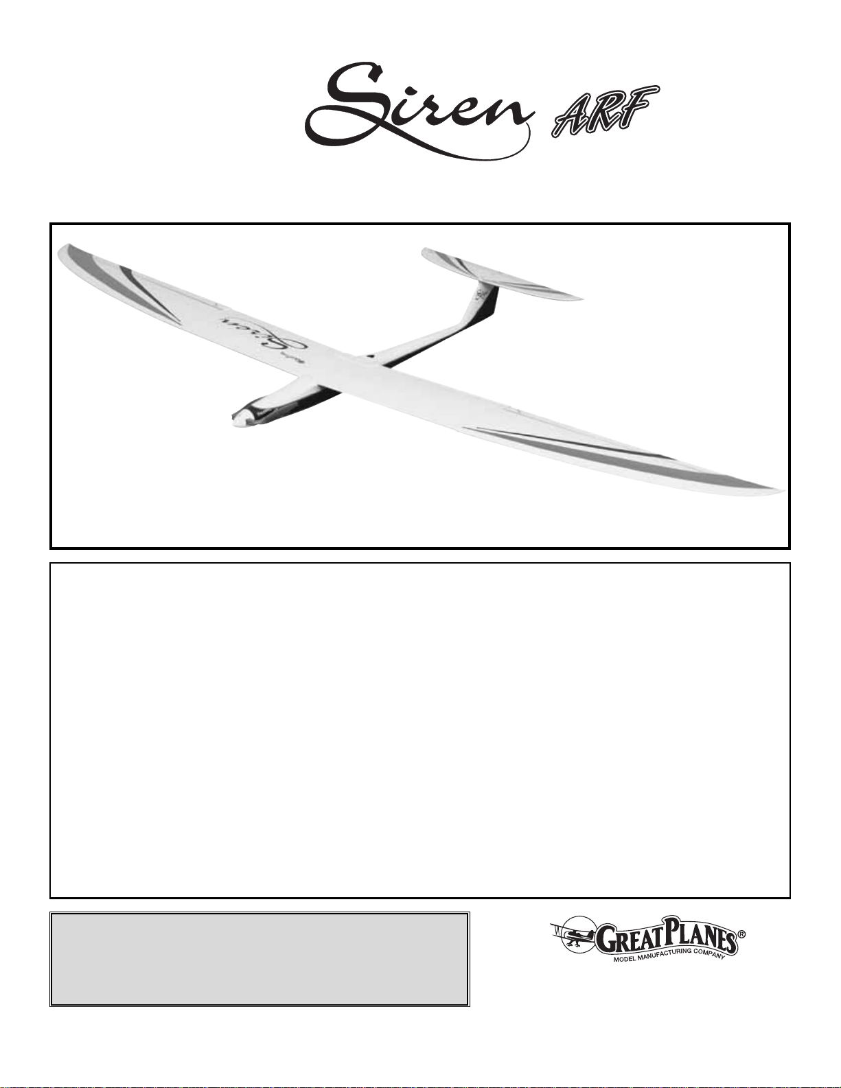
The Great Planes Siren
™
ARF is a high-performance
electric sailplane that performs well on a standard brushed
motor while delivering great performance on a brushless
motor. This is an electric powered glider that is very agile
and likes to fly fast. It is not, therefore, an airplane for the
beginner, but one for pilots with some experience. Unlike
many airplanes of this type, the Siren ARF is an honest
airplane. It will fly where you point it and has absolutely no
bad tendencies. Stalls are straight and smooth. The Siren
ARF also has good thermaling capabilities.
For the latest technical updates or manual corrections to the
Siren ARF visit the Great Planes web site at
www.g reatplanes.com
. Open the “Airplanes” link, and then
select the Siren ARF. If there is new technical information or
changes to this model a “tech notice” box will appear in the
upper left corner of the page.
We urge you to join the AMA (Academy of Model
Aeronautics) and a local R/C club. The AMA is the
governing body of model aviation and membership is
required to fly at AMA clubs. Though joining the AMA
provides many benefits, one of the primary reasons to join
is liability protection. Coverage is not limited to flying at
contests or on the club field. It even applies to flying at
public demonstrations and air shows.Failure to comply with
the Safety Code (excerpts printed in the back of the
manual) may endanger insurance coverage. Additionally,
training programs and instructors are available at AMA club
sites to help you get started the right way. There are over
2,500 AMA chartered clubs across the countr y.Contact the
AMA at the address or toll-free phone number below:
IMPORTANT!!! Two of the most important things you can
do to preserve the radio controlled aircraft hobby are to
avoid flying near full-scale aircraft and avoid flying near or
over groups of people.
1.Your Siren ARF should not be considered a toy, but rather
a sophisticated, working model that functions very much
like a full-size airplane. Because of its performance
capabilities, the Siren ARF, if not assembled and operated
correctly, could possibly cause injury to you or spectators
and damage to property.
2. You must assemble the model according to the
instructions. Do not alter or modify the model, as doing so
may result in an unsafe or unflyable model. In a few cases
the instructions may differ slightly from the photos.In those
PRO TECT YOUR MODEL,Y OURSELF
& OTHERS...FOLLOW THESE
IMPORTANT SAFETY PRECAUTIONS
Academy of Model Aeronautics
5151 East Memorial Drive
Muncie, IN 47302
Tele: (800) 435-9262
Fax (765) 741-0057
Or via the Internet at:
http://www.modelaircraft.org
AMA
INTRODUCTION
TABLE OF CONTENTS
2
Page 3

instances the written instructions should be considered
as correct.
3.You must take time to build straight, true and strong.
4. You must use an R/C radio system that is in first-class
condition and a correctly sized engine and components
(fuel tank, wheels, etc.) throughout the building process.
5.You must correctly install all R/C and other components so
that the model operates correctly on the ground and in the air.
6.You must check the operation of the model before every
flight to insure that all equipment is operating and that the
model has remained structurally sound. Be sure to check
clevises or other connectors often and replace them if they
show any signs of wear or fatigue.
7. If you are not an experienced pilot or have not flown this
type of model before, we recommend that you get the
assistance of an experienced pilot in your R/C club for your
first flights. If you’re not a member of a club, your local
hobby shop has information about clubs in your area whose
membership includes experienced pilots.
8.While this kit has been flight tested to exceed normal use, if
the plane will be used for extremely high-stress flying, such as
competition, or if a motor larger than one in the recommended
range is used, the modeler is responsible for taking steps to
reinforce the high-stress points and/or substituting hardware
more suitable for the increased stress.
9. WARNING: The fuselage included in this kit is made of
carbon fiber, the fibers of which may cause eye, skin and
respiratory tract irritation. Never blow into the fuselage to
remove dust, as the dust will blow back into your eyes.
Always wear safety goggles, a particle mask and rubber
gloves when grinding, drilling and sanding carbon fiber
parts.Vacuum the parts and the work area thoroughly after
working with carbon fiber parts.
Remember:Take your time and follow the instructions to
end up with a well-built model that is straight and true.
The Great Planes Siren ARF can be built either as a sport
electric sailplane or as an entry level hotliner.To fly the Siren
ARF as a sport sailplane you need a 600-size Great Planes
brushed motor with an 8-cell NiMH and an 8x4 folding
propeller.This setup delivers 20° climb out angles with a fullthrottle endurance of around 7 minutes.To fly the Siren ARF
as an entry level hotliner , you will need a K ontronik™Brushless
480 motor with gearbox, and a 10-cell NiMH battery turning a
13x7 APC folding propeller. With this setup the Siren ARF is
capable of three to four vertical climb outs at high speed.The
Siren ARF climbs to altitude in about 10 seconds. This is a
powerful setup that allows the airplane to deliver its full
performance potential, but it also demands more attention
from the pilot as extreme speeds are easy to achieve. Great
Planes offers both power packages as options. You must
choose a power package based on the performance you
expect out of the airplane. The motor mount installed on the
Siren ARF will fit both power packages.
Great Planes Brushed Sport Package
T-601 Ferrite Motor (GPMG0706)
Great Planes 8x4 folding propeller (GPMQ1650)
7-Cell 2000 mAh NiMH (GPMP0351)
8-Cell 2000 mAh NiHH (GPMP0352)
Great Planes Electrifly™C-30 Speed Control (GPMM2030)
Brushless Power Package
Kontronik 480 Brushless set (KONG5020) (includes motor,
gearbox, and speed controller)
APC 13x7 Folding Propeller (APCQ4357)
Great Planes Folding Propeller Spinner (GPMQ1651)
10-Cell 2000 mAh NiMH (GPMP0353)
In addition to the NiMH batteries specified above, Lithium
batteries can be used to power both power systems of the
Siren ARF. Using Lithium batteries will increase your flight
times substantially while decreasing the final weight of the
airplane slightly. the following are the recommended lithium
batteries for the Siren ARF.
Great Planes Brushed Sport Package
This power system requires two 7.4V 1500 mAh Li-Po
batteries wired in parallel for a 2S-2P configuration.
(2) Great Planes Lithium-Polymer 1500 mAh 7.4V 2-cell
pack (GPMP0830)
(2) W. S. Deans 2-Pin Ultra plug
(1) W. S. Deans Wet Noodle Flex 12-gauge red 2'/black 2'
Brushless Power Package
There are two options for this power package:
First Option:T w o 11.1 V 1500 mAh Li-Po batteries wired in
parallel for a 3S-2P configuration. This configuration will
deliver slightly less performance than the 10-cell NiMH
pack, but the run time will be increased to 5-6 minutes.
(2) Great Planes Lithium-Polymer 1500 mAh 11.1V 3-cell
Pack (GPMP0831)
Using Lithium Batteries
Motor Recommendations
DECISIONS YOU MUST MAKE
We, as the kit manufacturer, provide you with a top
quality, thoroughly tested kit and instructions, but
ultimately the quality and flyability of your finished model
depends on how you build it;therefore, we cannot in any
way guarantee the performance of your completed
model, and no representations are expressed or implied
as to the performance or safety of your completed model.
3
Page 4

(2) W. S. Deans 2-Pin Ultra Plug
(1) W. S. Deans Wet Noodle Flex 12-gauge red 2'/black 2'
Second Option: Four 7.4V 1500mAh Li-Po batteries wired
in series and parallel for a 4S-2P configuration. This
configuration will deliver the highest performance and 4-5
minutes of run time.
(4) Great Planes Lithium-Polymer 1500mAh 7.4V 2-cell
Pack (GPMP0830)
(4) W.S. Deans 2-Pin Ultra Plug
(1) W.S. Deans Wet Noodle Flex 12-gauge red 2'/black 2'
WARNING!! Read the entire instruction sheet included with
this battery. Failure to follow all instructions could cause
permanent damage to the battery and its surroundings, and
cause bodily harm!
• ONLY use a Li-Po approved charger. NEVER use a
NiCd/NiMH peak charger!
• NEVER charge in excess of 4.20V per cell.
• ONLY charge through the “charge” lead.NEVER charge
through the “discharge” lead.
• NEVER charge at currents greater than 1C.
• ALWAYS set charger’s output volts to match battery volts.
• ALWAYS charge in a fireproof location.
• NEVER trickle charge.
• NEVER allow the battery temperature to exceed 150° F
(65° C).
• NEVER disassemble or modify pack wiring in any way
or puncture cells.
• NEVER discharge below 2.5V per cell.
• NEVER place on combustible materials or leave
unattended during charge or discharge.
• ALWAYS KEEP OUT OF REACH OF CHILDREN.
The Siren ARF requires a radio with a minimum of three
channels (throttle, elevator and ailerons). The transmitter
should have a throttle stick, not a slider, especially when using
the powerful brushless power package (the stick allows for
more precise throttle control).The motor speed control should
have a BEC to pow er the radio.The servos recommended for
this airplane are good quality servos with at least 16 oz-in
[1.2kg-cm] of torque such as the Futaba®S3107 Nano servo
or the Hobbico®CS-5 Micro servo. Should you choose a
different brand of servo, make sure they use slop-free gears
and that they center well and fit in place.Lower quality servos
can cause flutter and destroy an airplane quickly.
Futaba®S3107 Nano Servo (FUTM0025)
Hobbico CS-5 Servo (HCAM0090)
In addition to the items listed in the “
Decisions You Must
Make”
section, following is the list of hardware and
accessories required to finish the Siren ARF. Order
numbers are provided in parentheses.
❏ Small Phillips screwdriver (#1)
❏ (3) 24" Servo extension (HCAM2200 for Futaba)
❏ “Y” harness (FUTM4130 for Futaba)
❏ Transparent tape
❏ Great Planes 3/8" heat shrink tubing (GPMM1060)
❏ Trinity
®
pre-cut single cell heat shrink tubing (TRIC6074)
❏ Hobbico
®
1/4" [6mm] foam (HCAQ1000)
In addition to common household tools and hobby tools, this
is the “short list” of the most important items required to
build the Siren ARF.
Great Planes Pro™CA and Epoxy glue
are recommended.
❏ Pro 6-minute epoxy (GPMR6045)
❏ Pro 30-minute epoxy (GPMR6047)
❏ #11 blades (5-pack, HCAR0211)
❏ Stick-on segmented lead weights (GPMQ4485)
❏ Allen wrenches for the motor screws
❏ Flat screwdriver
Here is a list of optional tools mentioned in the manual that
will help you build the Siren ARF.
❏ Epoxy brushes (6, GPMR8060)
❏ Mixing sticks (50, GPMR8055)
❏ Mixing cups (GPMR8056)
❏ Pliers with wire cutter (HCAR0630)
❏ Masking tape (TOPR8018)
❏ Threadlocker
™
thread-locking cement (GPMR6060)
❏ Rotary tool such as Dremel
®
❏ AccuThrow
™
Deflection Gauge (GPMR2405)
❏ Denatured alcohol (for epoxy clean up)
Optional Supplies & Tools
Adhesives & Building Supplies
Hardware & Accessories
ADDITIONAL ITEMS REQUIRED
Radio Equipment
Lithium Battery Handling & Usage
4
Page 5

Machine screws are designated b y a number, threads per
inch, and a length – for example, 4-40 x 3/4" [19mm].
This is a number four screw that is 3/4" long with forty
threads per inch.
• When you see the term
test fit
in the instructions, it
means that you should first position the part on the
assembly without using any glue, then slightly modify or
custom fit
the part as necessar y for the best fit.
• Whenever the term
glue
is written you should rely upon
your experience to decide what type of glue to use.When a
specific type of adhesive works best for that step, the
instructions will make a recommendation.
• Whenever just
epoxy
is specified you may use
either
30-minute (or 45-minute) epoxy or6-minute epoxy. When
30-minute epoxy is specified it is highly recommended that
you use only 30-minute (or 45-minute) epoxy, because you
will need the working time and/or the additional strength.
•
Photos
and
sketches
are placed before the step they
refer to. Frequently you can study photos in following steps
to get another view of the same parts.
• The stabilizer and wing incidences and engine thrust
angles have been f actory-built into this model.Howev er , some
technically-minded modelers may wish to check these
measurements anyway.To view this information, visit the web
site at
www
.greatplanes.com
and click on “Technical Data.”
Due to manufacturing tolerances which will have little or no
effect on the way your model will fly, please expect slight
deviations between your model and the published values.
Fuse = Fuselage
Stab = Horizontal Stabilizer
Fin = Ver tical Fin
LE = Leading Edge
TE = Trailing Edge
LG = Landing Gear
" = Inches
mm = millimeters
COMMON ABBREVIATIONS
IMPORTANT BUILDING NOTES
5
Page 6
6
Replacement parts for the Great Planes Siren ARF are available using the order numbers in the Replacement Parts List
that follows.The fastest, most economical service can be provided by your hobby dealer or mail-order company.
To locate a hobby dealer, visit the Hobbico web site at
www.hobbico.com
. Choose “Where to Buy” at the bottom of the
menu on the left side of the page.Follow the instructions provided on the page to locate a U.S ., Canadian or International
dealer. If a hobby shop is not available, replacement parts may also be ordered from Tower Hobbies at
www.towerhob
bies.com
, or by calling toll free (800) 637-6050.
Parts may also be ordered directly from Hobby Services by calling (217) 398-0007, or via f acsimile at (217) 398-7721, but
full retail prices and shipping and handling charges will apply.Illinois and Nevada residents will also be charged sales tax.
If ordering via fax, include a Visa®or MasterCard®number and expiration date for payment.
Mail parts orders and payments by personal check to:
Hobby Services
3002 N Apollo Drive, Suite 1
Champaign, IL 61822
Be certain to specify the order number exactly as listed in the Replacement Parts List. Payment by credit card or
personal check only; no C.O.D.
If additional assistance is required for any reason contact Product Support by e-mail at
productsuppor
t@greatplanes.com
,
or by telephone at (217) 398-8970.
Replacement Parts List
Order Number Description How to Purchase
Missing pieces.....................Contact Product Suppor t
Instruction manual...............Contact Product Suppor t
Full-size plans.....................Not available
GPMA2780 Wing Kit
GPMA2781 Fuse Kit
GPMA2782 Stabilizer
GPMA2783 Decal Sheet
GPMQ1650 Sport Spinner/Propeller
GPMQ1651 Brushless Spinner
ORDERING REPLACEMENT PARTS
................
Contact Your Hobby
Supplier to Purchase
These Items
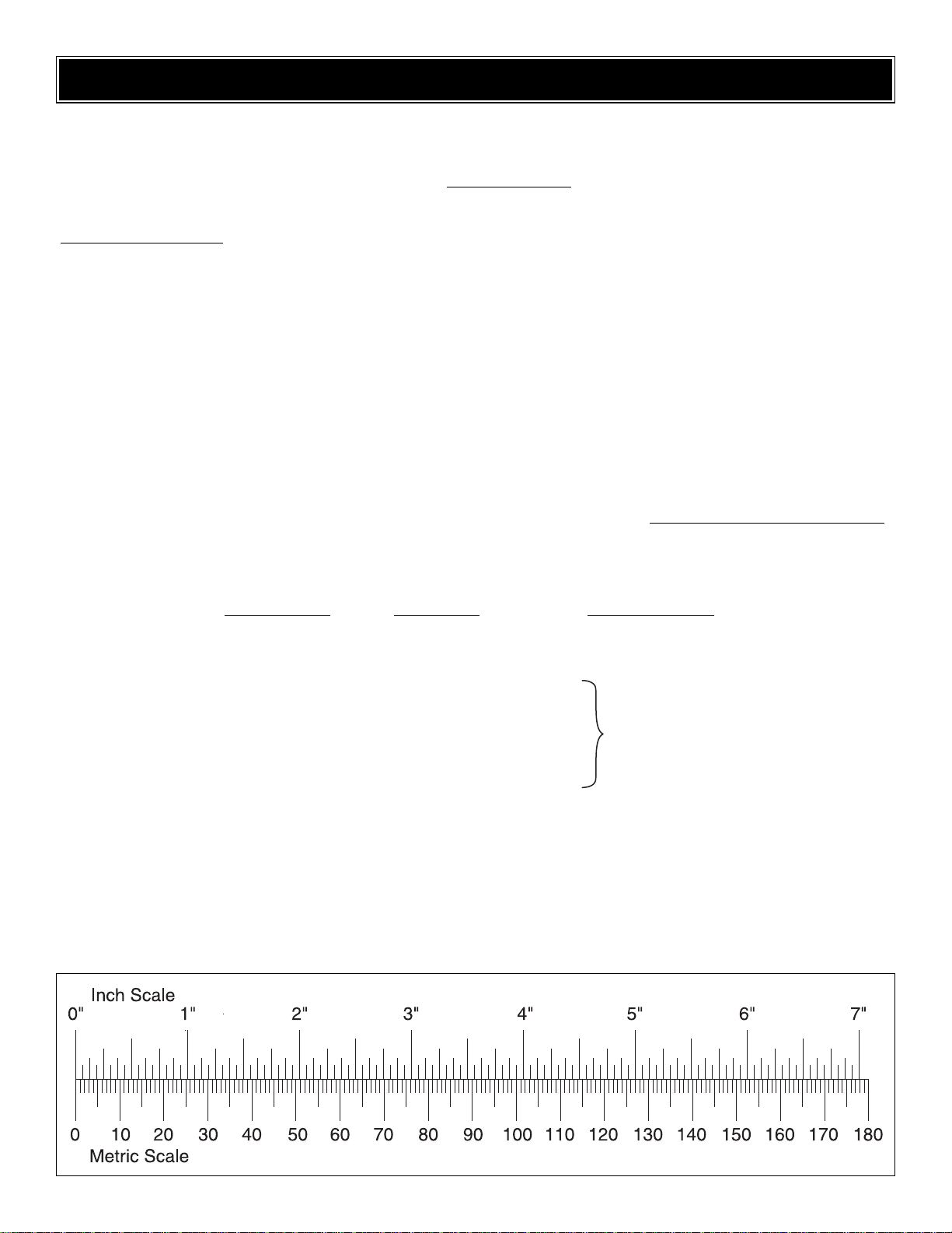
To convert inches to millimeters, multiply inches by 25.4
Page 7

7
1. Fuselage
2. Servo Cover
3. Wing Joiners (10)
4. Pushrods (3)
5. Wing Center-Section
6. Horizontal Stabilizer
7. Outer Wing Panels (2)
Kit Contents (not photographed)
Kit Contents
(3) Small Control Horns
(3) 2mm x 150mm Pushrods (threaded one end)
(3) 2mm Nylon Clevises
(3) Silicone Retainers
(3) Nylon FasLinks
(1) 1/4-20 x 1" Nylon Bolt
(1) 1/4-20 Blind Nut (pre-installed in fuse)
(6) 2-56 x 5/8" Machine Screws
(8) 2mm x 9mm Screws
(2) 10-32 x 2" Nylon Bolt
(1) Velcro
®
Strip
Before starting to build, take an inventory of this kit to make sure it is complete, and inspect the parts to make sure they
are of acceptable quality. If any parts are missing or are not of acceptable quality, or if you need assistance with assembly,
contact Product Support. When reporting defective or missing parts, use the part names exactly as they are written in
the Kit Contents list.
Great Planes Product Support:
3002 N Apollo Drive, Suite 1
Champaign, IL 61822
Telephone: (217) 398-8970, ext. 5
Fax:(217) 398-7721
E-mail:
airsupport@g
reatplanes.com
KIT CONTENTS
1
2
6
5
3
4
7
Page 8

❏❏1.Locate five 1/16" [1.6mm] ply wing joiner plates.Mix
a generous amount of 6-minute epoxy and glue the plates
together.Clean up excess epoxy with denatured alcohol and
a paper towel.Allow the epoxy to harden before proceeding.
❏❏2. Test fit the joiner into the wing center-section. The
smaller end of the joiner will slide into the wing centersection.The fit should be snug. If not, sand the joiner plates
as needed for a good fit. Also test fit one of the wing outer
panels and sand the wing joiner as needed for a good snug
fit. Glue the smaller end of the wing joiner into the wing
center-section using 6 minute epoxy. Make sure the wing
joiner is coated thoroughly with epoxy to ensure a good
bond. Remove any excess epoxy that squeezes out with
denatured alcohol and a paper towel.T ry not to leave e xcess
epoxy on the center-section rib as it will make for a poor
wing fit.Allow the epoxy to harden before proceeding.Install
a 24" [610mm] extension through the wing center-section.
❏❏3.Cut away the cov ering from the servo bay.Using 30-
minute epoxy, coat the wing joiner, wing center-section rib,
and wing outer panel. Attach the wing outer panel. Route
the servo extension from the center-section into the servo
bay. Clean up any excess epoxy with denatured alcohol and
a paper towel. Align the trailing edge of the center-section
and the outer panel. Hold the two in place using masking
tape while the epoxy hardens.
❏ 4. Repeat steps 1-3 for the other side of the wing.
❏ 5. Inspect the hinges and the hinging motion of the
ailerons now and before each flight.
The servos in this model are mounted with heat shrink
tubing (not included). If you wish to do so, you can carefully
remove the mounting tabs on the servos. A sharp hobby
knife works well for this.
❏❏1. Using a piece of Trinity Single Cell heat shrink tubing,
fit the tubing over the servo and heat shrink it.This will allow
you to easily replace the servo later since the tubing will be
glued in place, not the servo.
❏❏2. Connect the servo lead to the 24" [610mm] servo
extension.Secure the connection with a 1-1/2" [38mm] piece of
Install the Aileron Servos
Attach the Wing Tips
ASSEMBLE THE WING
8
Page 9

3/8" [10mm] heat shrink tubing to prevent the leads from
becoming disconnected.
❏❏3.Tempor arily attach the servo to the receiver .T urn on the
radio and center the servo.Test fit the servo in the servo bay.
Adjust the servo arm until one of the arms is at a 90° angle to
the bottom of the wing. Cut off the remaining servo arms and
tack glue the servo in place with a drop of medium CA.
❏❏4. Thread a nylon clevis twenty turns onto the threaded
end of a 2mm x 150mm threaded pushrod. Slide a clevis
retainer over the cle vis.Attach the clevis to the outer hole of
a small nylon control horns.
❏❏5. Align the holes in the control horn with the hinge line,
keeping the pushrod aligned with the servo arm. Mount the
control horn using two 2-56 x 5/8 [16mm] machine screws.Use
the backing nylon plate on the other side of the aileron.
❏❏6.Mark the pushrod where it crosses the servo arm. Make
a 90° bend at the mark and push through the servo arm. Attach
a nylon FasLink and trim off the excess pushrod, leaving
approximately 1/16" [1.6mm] past the FasLink. Remove the
elevator servo.
❏❏7. Carefully trim the ser vo cover along the cutlines.
Lightly sand the area of the heat shrink servo wrap that will
be glued to the wing. Align the ser vo so that the pushrod
clears the cover. The servo travel should not bind against
the servo cover. When you have everything lined up, glue
the servo in place using epoxy.
❏❏8. Mark the location of the servo cover screws on the
wing. Drill a 1/16" [1.6mm] hole at that location. Harden the
9
Page 10

hole with CA. Attach the servo cover to the wing using four
2mm x 9mm wood screws.
❏ 9. Repeat Steps 1-8 for the other aileron servo.
❏ 1. Inspect the hinges and the hinging motion of the
elevator now and before each flight. Cut the 10-24 x 2"
[52mm] nylon bolts to 3/4" [19mm] long.Attach the stab to the
fuse using the two nylon bolts.Be careful not to overtighten.
❏ 2. Cut the remaining small control horn as shown.The horn
is installed centered on the opening in the top of the fin and the
base of the horn is 1/2" [12mm] back from the hinge line.Install
the control horn using two 2-56 x 5/8" [16mm] bolts and the
nylon backplate.Remove the stab from the fuselage.
❏ 3. Remove the elevator servo hatch cover and set aside
for now.Cover the elevator servo with Trinity single cell heat
shrink as you did before on the aileron servos.
❏ 4. Connect a 24" [610mm] servo e xtension to the ele vator
servo. Secure the connection with 3/8" [10mm] heat shrink
tubing. Route the servo lead through the fuselage.
❏ 5. Temporarily position the elevator servo as shown.Use
fine-grit sandpaper to sand the area on the fuselage and
heat shrink wrap where the servo will be glued. Note:
Alternatively the servo can also be installed right-side up.
❏ 6. Thread a nylon clevis and retainer onto a 2mm x
150mm threaded pushrod. Make a Z-bend approximately
4-1/4" [108mm] from the end of the threaded end of the rod.
Connect the Z-bend to the elevator control horn & reinstall
the stabilizer while sliding the pushrod into the fin.
❏ 7. Center the ser vo and attach the clevis to the servo
arm. Shift the servo to get the elevator neutral and the top
of the servo parallel with the pushrod.
Mount the Stabilizer
ASSEMBLE THE FUSELA GE
10
Page 11

❏ 8. When you have the proper angle set, permanently
mount the servo using epoxy. Make sure that the servo is
securely glued in place after the epoxy has cured.
❏ 9. It may be necessary to widen the opening in the top of
the fin, or to remove a portion of the opening to allow the
pushrod to travel.
❏ 10. Use an epoxy bottle or similar to draw a 1-5/8"
[41mm] circle on the decal material. Cut the circle out. Use
this decal material to secure the tail servo cover to the fin.
❏ 1. Connect the motor to the ESC following the
manufacturer’s instructions.
❏ 2. Guide the motor into the nose of the airplane from the
inside of the fuselage.Secure the motor to the firewall using
screws provided by the motor manufacturer and threadlocking compound.
Brushless Motor Installation
Warnings Before Motor System Installation
• The power system you are just about to install is very
high power and it needs to be handled carefully to av oid
serious injury.Both the Brushless motor installation and
the Brushed motor installations are capable of
producing injury at any throttle setting.
• Make sure when doing these installations that the radio
system is set to the lowest throttle setting at all times.
• Do not plug in the motor battery to the motor ESC at any
point until directed to do so.
• Under no circumstances should the radio system in the
airplane be switched on before the transmitter is
switched on.
• Do not plug the battery in the airplane to the ESC until the
transmitter is on and transmitting and throttle is at idle.
• Never stand or have any part of your body near the
propeller when the motor battery is connected.
• Watch out for loose clothing or other objects in the path
of the propeller.
• Securely hold the model when testing the motor.
• Always test the motor outdoors. Never turn on the
motor indoors.
• Exercise extreme caution when handling the model
with the propeller on.
Install the Motor
11
Page 12

❏ 3. Check for proper motor rotation. Attach the prop adapter,
adapter washer, prop, and spinner to the motor shaft as
determined by the motor manufacturer.
❏ 1. Solder the motor to the ESC following the
manufacturer’s instructions.
❏ 2. Guide the motor into the nose of the airframe from the
inside of the fuselage. Mount the motor to the firewall using
the screws that came with the motor and Threadlocker.
❏ 3. Check for proper motor rotation. Attach the prop
adapter, prop, and spinner to the motor shaft as determined
by your manufacturer.
Brushed Motor Installation
12
Page 13

❏ 1. Connect the elevator, ESC, and aileron Y-harness to
the receiver. Mount the receiver in the rear of the radio
compartment with double-sided tape.
❏ 2. Drill a small hole as shown for the antenna to exit
the fuse. Do not route the antenna inside the carbon
fiber fuselage!
❏ 3. Slide the battery into the radio compartment. DO NOT
CONNECT THE BATTERY TO THE ESC AT THIS TIME.
Use 1/4" [6mm] foam to hold the battery in place. Adding
foam to the front or back of the battery compartment can be
helpful in shifting the battery location for balancing. The
battery will be a tight fit. Glue Velcro with CA or epo xy to the
bottom side of the battery and to the battery tray to hold the
battery in place.
❏ 4. If the battery does not slide forward far enough to fit
inside the fuselage, tack glue the hardwood wedge on the
battery tray against the forward former. This wedge will lift
the front of the battery and it will help it slide through the
forward former easily.
1.Use scissors or a sharp hobby knife to cut the decals from
the sheet.
2. Be certain the model is clean and free from oily fingerpr ints
and dust. Prepare a dishpan or small bucket with a mixture of
liquid dish soap and warm water–about one teaspoon of soap
per gallon of water.Submerse the decal in the soap and water
and peel off the paper backing. Note: Even though the decals
have a “sticky-back” and are not the water transfer type,
submersing them in soap and water allows accurate positioning
and reduces air bubbles underneath.
3. Position decal on the model where desired or use the
airplane’s box as a guide. Holding the decal down, use a
paper towel to wipe most of the water away.
4. Use a piece of soft balsa or something similar to
squeegee remaining water from under the decal. Apply the
rest of the decals the same way.
Note: Exercise extreme caution when handling the
model with the propeller on.
❏ 1. Tur n on the transmitter and receiver and center the
trims. If necessary, remove the servo arms from the servos
and reposition them so they are centered. Reinstall the
screws that hold on the servo arms.The throttle stick should
be at the idle or low position.
❏ 2. With the transmitter and receiver still on, check all the
control surfaces to see if they are centered.If necessary, adjust
the clevises on the pushrods to center the control surfaces.
Check the Control Directions
GET THE MODEL READY TO FLY
Apply the Decals
Receiver & Battery Installation
13
Page 14

❏ 3. Make certain that the control surfaces and the throttle
respond in the correct direction as shown in the diagram. If
any of the controls respond in the wrong direction, use the
servo reversing in the transmitter to reverse the servos
connected to those controls. Be certain the control surfaces
have remained centered.Adjust if necessar y.
Use a Great Planes AccuThrow™(or a ruler) to accurately
measure and set the control throw of each control surface
as indicated in the chart that follows. If your radio does not
have dual rates, we recommend setting the throws at the
middle of both rate settings.
Note: The throws are measured at the widest part of the
elevators, rudder and ailerons.
At this stage the model should be in ready-to-fly condition
with all of the systems in place including the motor, battery,
finishing, and the radio system.
❏ 1. Use a f elt-tip pen or 1/8" [3mm]-wide tape to accurately
mark the C.G.on the bottom of the wing on both sides of the
fuselage. The C.G. is located 2-1/8" [55mm] back from the
leading edge of the wing.
❏ 2.With the wing attached to the fuselage and all parts of the
model installed (ready to fly), place the model on a Great Planes
CG Machine™, or lift it at the balance point you marked.
This is where your model should balance for the first
flights. Later, you may wish to experiment by shifting the
C.G. up to 3/8" [9mm] forward or 3/8" [10mm] back to
change the flying characteristics.Moving the C.G.forward
may improve the smoothness and stability, but the model
may be more difficult to slow for landing. Moving the C.G.
aft makes the model more maneuverable, but could also
cause it to become too difficult to control. In any case,
start at the recommended balance point and do not at
any time balance the model outside the specified range.
More than any other factor, the C.G. (balance point) can
have the greatest effect on how a model flies, and may
determine whether or not your first flight will be
successful. If you value this model and wish to enjoy it for
many flights, DO NOT OVERLOOK THIS IMPORTANT
PROCEDURE. A model that is not properly balanced will
be unstable and possibly unflyable.
Balance the Model (C.G.)
IMPORTANT: The Siren ARF has been extensively
flown and tested to arrive at the throws at which it flies
best. Flying your model at these throws will provide you
with the greatest chance for successful first flights.If, after
you have become accustomed to the way the Siren ARF
flies, you would like to change the throws to suit your
taste, that is fine. However, too much control throw could
make the model difficult to control, so remember , “more is
not always better.”
These are the recommended control surface throws:
High Rate Low Rate
ELEVATOR: 1/2" [12mm] up 5/16" [8mm] up
1/2" [12mm] down 5/16" [8mm] down
AILERONS: 3/8" [9mm] up 3/16" [5mm] up
3/8" [9mm] down 3/16" [5mm] down
Set the Control Throws
14
Page 15

❏ 3. If the tail drops, the model is “tail heavy” and the
battery pack and/or receiver must be shifted forward or
weight must be added to the nose to balance. If the nose
drops, the model is “nose heavy” and the battery pack
and/or receiver must be shifted aft or weight must be added
to the tail to balance. If possible, relocate the battery pack
and receiver to minimize or eliminate any additional ballast
required.If relocating the battery pack and receiver does not
correct the balance of the Siren ARF you may use Great
Planes (GPMQ4485) “stick-on” lead. Begin by placing
incrementally increasing amounts of weight on the fuse over
the firewall until the model balances. Once you have
determined the amount of weight required, it can be
permanently attached.
Note: Do not rely upon the adhesive on the back of the lead
weight to permanently hold it in place. Use RTV silicone or
epoxy to permanently hold the weight in place.
❏ 4. IMPORTANT: If you found it necessary to add any
weight, recheck the C.G.after the weight has been installed.
❏ 1. With the wing level, have an assistant help you lift the
model by the motor propeller shaft and the bottom of the
fuse under the TE of the fin.Do this several times.
❏2.If one wing always drops when you lift the model, it means
that side is heavy. Balance the airplane by adding weight to the
other wing tip. An airplane that has been laterally balanced
will track better in loops and other maneuvers.
No matter if you fly at an AMA sanctioned R/C club site or if you
fly somewhere on your own, you should always have your
name, address, telephone number and AMA number on or
inside your model.It is required at all AMA R/C club flying sites
and AMA sanctioned flying events. Fill out the identification tag
on page 18 and place it on or inside your model.
Follow the battery charging instructions that came with your
radio control system to charge the batteries in your
transmitter.You should always charge your transmitter and
receiver batteries the night before you go flying, and at other
times as recommended by the radio manufacturer.
Ground check the operational range of your r adio bef ore the
first flight of the day. With the transmitter antenna collapsed
and the receiver and transmitter on, you should be able to
walk at least 100 feet away from the model and still have
control. Have an assistant stand by your model and, while
you work the controls, tell you what the control surfaces are
doing. Repeat this test with the motor running at various
speeds with an assistant holding the model, using hand
signals to show you what is happening. If the control
surfaces do not respond correctly, do not fly! Find and
correct the problem first. Look for loose servo connections
or broken wires, corroded wires on old servo connectors,
poor solder joints in your battery pack or a defective cell, or
a damaged receiver crystal from a previous crash.
Get help from an experienced pilot when learning to operate
a motor of this power.
Use safety glasses when starting or running motors.
Do not run the motor in an area of loose gravel or sand;the
propeller may throw such material in your face or eyes.
Keep your f ace and body as well as all spectators a wa y from
the plane of rotation of the propeller as you start and run
the motor.
Keep these items away from the prop: loose clothing, shirt
sleeves, ties, scarfs, long hair or loose objects such as
pencils or screwdrivers that may fall out of shirt or jacket
pockets into the prop.
The motor gets hot! Do not touch it during or immediately
after operation.
Failure to follow these safety precautions may result
in severe injury to yourself and others.
MOTOR SAFETY PRECAUTIONS
Range Check
CAUTION: Unless the instructions that came with your
radio system state differently, the initial charge on new
transmitter and receiver batteries should be done for 15
hours using the slow-charger that came with the radio
system.This will “condition” the batteries so that the next
charge may be done using the fast-charger of your
choice. If the initial charge is done with a fast-charger the
batteries may not reach their full capacity and you may be
flying with batteries that are only partially charged.
Charge the Batteries
Identify Y our Model
PREFLIGHT
Balance the Model Laterally
15
Page 16

Read and abide by the following e xcerpts from the Academy
of Model Aeronautics Safety Code.For the complete Safety
Code refer to
Model Aviation
magazine, the AMA web site
or the Code that came with your AMA license.
GENERAL
1. I will not fly my model aircraft in sanctioned events, air
shows, or model flying demonstrations until it has been
proven to be airworthy by having been previously,
successfully flight tested.
2. I will not fly my model aircraft higher than approximately
400 feet within 3 miles of an airport without notifying the
airpor t operator. I will give right-of-way and avoid flying in
the proximity of full-scale aircraft. Where necessary, an
observer shall be utilized to supervise flying to avoid having
models fly in the proximity of full-scale aircraft.
3.Where established, I will abide by the safety rules for the
flying site I use, and I will not willfully and deliberately fly my
models in a careless, reckless and/or dangerous manner.
5. I will not fly my model unless it is identified with my name
and address or AMA number, on or in the model.Note: This
does not apply to models while being flown indoors.
7. I will not operate models with pyrotechnics (any device
that explodes, burns, or propels a projectile of any kind).
RADIO CONTROL
1. I will have completed a successful radio equipment ground
check before the first flight of a new or repaired model.
2. I will not fly my model aircraft in the presence of
spectators until I become a qualified flier, unless assisted b y
an experienced helper.
3. At all flying sites a straight or curved line(s) must be
established in front of which all flying takes place with the
other side for spectators.Only personnel involv ed with flying
the aircraft are allowed at or in the front of the flight line.
Intentional flying behind the flight line is prohibited.
4. I will operate my model using only radio control frequencies
currently allowed by the F ederal Comm unications Commission.
5. I will not knowingly operate my model within three
miles of any pre-existing flying site except in
accordance with the frequency sharing agreement
listed [in the complete AMA Safety Code].
9.Under no circumstances may a pilot or other person touch
a powered model in flight; nor should any part of the
model other than the landing gear, intentionally touch
the ground, except while landing.
❏ 1. Check the C.G. according to the measurements
provided in the manual.
❏ 2. Be certain the battery and receiver are securely
mounted in the fuse. Simply stuffing them into place
is not sufficient.
❏ 3. Extend your receiver antenna and make sure it has a
strain relief inside the fuselage to keep tension off the
solder joint inside the receiver.
❏ 4. Balance your model
laterally
as explained in the
instructions.
❏ 5. Use thread-locking compound to secure critical.
❏ 6. Make sure all hinges are securely in place.
❏ 7. Confirm that all controls operate in the correct direction
and the throws are set up according to the manual.
❏ 8. Make sure there are silicone retainers on all the
clevises and that all servo arms are secured to the
servos with the screws included with your radio.
❏ 9. Secure connections between servo wires and
Y-connectors or servo extensions, and the
connection between your battery pack and the on/off
switch with vinyl tape, heat shrink tubing or special
clips suitable for that purpose.
❏ 10. Make sure any servo extension cords you may have
used do not interfere with other systems (servo arms,
pushrods, etc.).
❏ 11. Balance your propeller (and spare propellers).
❏ 12. Tighten the propeller nut and spinner.
❏ 13.Place your name, address, AMA number and
telephone number on or inside your model.
❏ 14. Cycle your battery pack (if necessary) and make sure
it is fully charged.
❏ 15. If you wish to photograph your model, do so before
your first flight.
❏ 16. Range check your radio when you get to the flying field.
The Siren ARF is a great-flying model that flies smoothly
and predictably. The Siren ARF does not, however, possess
the self-recovery characteristics of a primary R/C trainer
and should be flown only by experienced R/C pilots.
FLYING
During the last few moments of preparation your mind
may be elsewhere anticipating the excitement of the first
flight. Because of this, you may be more likely to ov erlook
certain checks and procedures that should be performed
before the model is flown.To help avoid this, a check list
is provided to make sure these important areas are not
overlooked. Many are covered in the instruction manual,
so where appropriate, refer to the manual for complete
instructions. Be sure to check the items off as they are
completed (that’s why it’s called a
check list!
).
CHECK LISTAMA SAFETY CODE (excerpts)
16
Page 17

Remember to launch into the wind.When you’ re ready, point
the model straight into the wind, and apply full throttle.
Throw the model straight and level with a good toss.If using
the brushed power package, the Siren ARF will fly off of
your hand and fly level until it picks up speed. The climb
angle will be around 20-30 degrees. If you are using the
brushless power package, the Siren ARF will fly off your
hand and start a vertical climb if you apply elevator. Using
this power system, you should keep in mind the amount of
power that your motor is producing and avoid prolonged
climbs. The model will climb rapidly and become a spec in
the sky within ten to fifteen seconds of launch.
For reassurance and to keep an e y e on other traffic , it is a good
idea to have an assistant on the flight line with you.Tell him to
remind you to throttle back once the plane gets to a comf ortable
altitude. While full throttle is usually desirable for takeoff, most
models fly more smoothly at reduced speeds.
Take it easy with the Siren ARF for the first few flights,
gradually getting acquainted with it as you gain confidence.
Adjust the trims to maintain straight and level flight. After
flying around for a while, and while still at a saf e altitude with
plenty of battery, practice slow flight and execute practice
landing approaches by reducing the throttle to see how the
model handles at slower speeds.Add power to see how she
climbs as well. Continue to fly around, executing various
maneuvers and making mental notes (or having your
assistant write them down) of what trim or C.G. changes
may be required to fine tune the model so it flies the wa y you
like. Mind your fuel level, but use this first flight to become
familiar with your model before landing.
If it is your intention to perform high-speed passes, then
make sure that you shut off power while at altitude before
diving. This way the folding propeller will fold and the
airplane will pick up maximum speed.
To initiate a landing approach, lower the throttle while on the
downwind leg. Allow the nose of the model to pitch
downward to gradually bleed off altitude. Continue to lose
altitude, but maintain airspeed by k eeping the nose do wn as
you turn onto the crosswind leg.Make your final turn toward
the runway (into the wind) keeping the nose down to
maintain airspeed and control. Level the attitude when the
model reaches the runway threshold. If you are going to
overshoot, smoothly advance the throttle and climb out to
make another attempt. When you’re ready to make your
landing flare and the model is a foot or so off the deck,
smoothly increase up elevator until it gently touches down.
The Siren ARF is a very efficient electric glider and as such
it will lose very little altitude as it glides. Keep some reserve
power in the first few landings to get used to its gliding path.
One final note about flying your model.Have a goal or flight
plan in mind for every flight. This can be learning a new
maneuver(s), improving a maneuver(s) y ou already know, or
learning how the model behaves in certain conditions (such
as on high or low rates).This is not necessar ily to improve
your skills
(though it is never a bad idea!)
, but more
importantly so you do not surprise yourself by impulsively
attempting a maneuver and suddenly finding that you’v e run
out of time, altitude or airspeed. Every maneuver should be
deliberate, not impulsive.For example, if you’re going to do
a loop, check your altitude, mind the wind direction
(anticipating rudder corrections that will be required to
maintain heading), remember to throttle back at the top, and
make certain you are on the desired rates (high/low rates).
A flight plan greatly reduces the chances of crashing your
model just because of poor planning and impulsive moves.
Remember to think.
Have a ball! But always stay in control and fly in a
safe manner.
GOOD LUCK AND GREAT FLYING!
Landing
Flight
Takeoff
CAUTION (THIS APPLIES TO ALL
R/C AIRPLANES): If,
while flying, you notice an alarming or unusual sound
such as a low-pitched “buzz,” this may indicate control
surface
flutter
. Flutter occurs when a control surface
(such as an aileron or elevator) or a flying surface (such
as a wing or stab) rapidly vibrates up and down (thus
causing the noise). In extreme cases, if not detected
immediately, flutter can actually cause the control surface
to detach or the flying surface to fail, thus causing loss of
control followed by an impending crash.The best thing to
do when flutter is detected is to slow the model
immediately by reducing power, then land as soon as
safely possible. Identify which surface fluttered (so the
problem may be resolved) by checking all the servo
grommets for deterioration or signs of vibration. Make
certain all pushrod linkages are secure and free of play.If
it fluttered once, under similar circumstances it will
probably flutter again unless the problem is fixed. Some
things which can cause flutter are; Excessive hinge gap;
Not mounting control horns solidly; Poor fit of clevis pin in
horn; Side-play of wire pushrods caused by large bends;
Excessive free play in servo gears; Insecure servo
mounting;and one of the most prevalent causes of flutter;
Flying an over-powered model at excessive speeds.
17
Page 18

Use this tag or photocopy it and use the copy. Please fill in the
indicated information and place the tag in or on your model.
Great Planes Spirit Elite
™
ARF
Like the International Model of the Year kit version, the
MonoKote®-covered, 2-meter Spirit Elite ARF 4-6 channel
sailplane is ideal for competition – with rudder, elevator,
ailerons, flaps, and balsa/ply wing panels that employ an SA
7035 root airfoil for speed and SA 7036 airf oil at the wingtips
for low-speed stability and lift.The fuselage is durable, gelcoated white fiberglass, shaped to reduce drag. Assembly
time is minimal...leaving you more time f or set-up , flight, and
experimenting with mixes! Requires a 4-6 channel radio with
4-6 mini or micro servos. GPMA1047
Great Planes ElectroStreak™ARF
This swift, sporty aerobat is ready in just 8-10 hours for clean,
quiet electric flight! All major sections are preassembled, then
covered with Top Flite
®
MonoKote film.The fuselage is made
of lightweight, hand-laid fiberglass that is gel-coated for a
sleek appearance. Remove two screws, and the balsa wing
comes off for easy transport.Quality Great Planes hardware is
included – along with a 550 motor, spinner, 8x5 folding prop
and electronic speed control with BEC. In the air, the
ElectroStreak ARF’s pull/pull rudder linkage saves space
compared to push/pull configurations, and offers efficient
power transfer without slop.GPMA1055
Great Planes Sukhoi SU-31 EP Park Flyer ARF
Now the nearest field for 3D aerobatics ma y be as close as your
own back yard! Built of ultra light materials, the Sukhoi SU-31
ARF can fly at speeds that would make other aircraft stall.Its low
weight also means that servos and control surfaces have less
mass to move and more power a vailable f or speed, strength and
agility. And because it’s an ARF, there’s less “wait” between
buying and flying, too. The Sukhoi SU-31 ARF can be flightready – and floating through its first flight – just a few hours after
you open the box! GPMA1185
ElectriFly
™
by Great Planes Triton™Peak Charger
Imagine a charger so versatile it can be used with lithiumion and lead-acid batteries as effectively as NiCd and NiMH
cells. A unit that can peak charge tiny park flyer packs and
24V car batteries alike.A charger that can discharge as well
as charge, cycle packs from 1 to 10 times automatically,
memorize peak and average battery voltages for each cycle
– and constantly display battery capacity, voltage, current
and time as each cycle progresses.Then, imagine that the
charger, which can do all this, is about the size of a thick
paperback book, and weighs just over a pound. The
advanced computer technology in the Triton Peak Charger
makes it possible to accomplish all this and more, through
controls and menus so simple that programming is a
breeze.For more information, log on at
www
.electrifly.com
–
and be amazed. 1-year warranty. GPMM3150
OTHER ITEMS AVAILABLE FROM
GREAT PLANES
18
Page 19

Hobbico®Pro Series™Accu-Cycle™Elite
Accu-Cycle Elite is an AC/DC charger, discharger and cycler in
one.It makes full, deep charges virtually effortless.Enter the cell
chemistry, voltage and capacity from your battery label, and its
Auto Smart Set will automatically set the safety-time-out period,
charge current and discharge voltage cut-off for Li-Ion/Li-Po
packs – and all three plus the trickle rate for NiCds and NiMHs.
You can also program custom battery routines and store them
in 10-battery memory.It can handle a single cell or a pack; one
of each simultaneously; or two cells or packs at once – even if
they’re of different chemistries. The large, 2-line,16-character
LCD make progress easy to see! HCAP0280
Great Planes ElectriFly 2000mAh Nickel-Metal
Hydride Battery
Be ready for launching fast with this preassembled and
shrink-wrapped 9.6V NiMH pack! Made with 4/5 sub-C cells,
it’s compact and lightweight – but offers a generous
2000mAh of capacity for long flight times. Includes a 2-pin
red charge connector.GPMP0352
Great Planes ElectriFly 1500mAh Lithium Polymer Battery
Lithium-Polymer (Li-P o) cells pro vide three times the voltage
of NiCd and NiMH cells – at less than half the weight!
Exclusive SafeCharge™circuitry protects ElectriFly Li-Po
packs by preventing any cell from overcharging.This 11.1V,
3 series pack includes a 2-pin red charge connector and
separate discharge connector.GPMP0831
Kontronik™Brushless Set 480
This high-RPM, gear driven motor system is ideal for
sailplanes and larger electric airplanes using 7-10 cells.
Lithium compatible, it includes the Fun 480-33 motor; Jazz
40-6-18 electronic speed control; and KPG25 gear drive
with 4.2:1 gear ratio. This system also makes an excellent
choice for converting most .40-.60 size glow-powered
trainers and sport models to electric power! KONG5020
Great Planes C.G. Precision Aircraft Balancer
Accurate balancing makes trainers more stable , low-wings more
agile, and pylon planes move at maximum speed. The
innovative C.G. Machine helps you achieve optimum balance
easily , without measuring or marking–and without the errors that
fingertip balancing can cause.Y ou’ll quic kly pinpoint your plane’ s
exact center of gravity. Then you’ll know at a glance whether
weight should be added, removed or relocated. The C.G.
Machine works with kits and ARF models of any size and
wingspan. Its slanted wire balancing posts support models
weighing up to 40 pounds. GPMR2400
19
Page 20

BUILDING NOTES
Kit Purchased Date: _______________________
Where Purchased: _________________________
Date Construction Started: __________________
Date Construction Finished: _________________
Finished Weight: __________________________
Date of First Flight: ________________________
FLIGHT LOG
 Loading...