

Page 1
WARRANTY
Great Planes®Model Manufacturing Co. guarantees this kit to be free from defects in both material and workmanship at the date of
purchase.This warranty does not cover any component parts damaged by use or modification. In no case shall Great Planes’liability
exceed the original cost of the purchased kit. Further, Great Planes reserves the right to change or modify this warranty without notice.
In that Great Planes has no control over the final assembly or material used for final assembly, no liability shall be assumed nor accepted
for any damage resulting from the use by the user of the final user-assembled product. By the act of using the user-assembled product,
the user accepts all resulting liability.
If the buyer is not prepared to accept the liability associated with the use of this product, the buyer is advised to return this kit
immediately in new and unused condition to the place of purchase.
READ THR OUGH THIS MANUAL BEFORE STARTING
CONSTRUCTION. IT CONTAINS IMPORTANT
INSTRUCTIONS AND WARNINGS CONCERNING
THE ASSEMBLY AND USE OF THIS MODEL.
GPMZ0236 for GPMA1055 V1.0 Entire Contents © Copyright 2001
1610 Interstate Drive Champaign, IL 61822
(217) 398-8970, Ext. 2
airsupport@greatplanes.com
INSTRUCTION MANUAL
Wingspan: 44.5 in [1130mm]
Wing Area: 342 sq in [22.03 dm
2
]
Weight: 43 oz. [1218g]
Wing Loading: 18.1 oz/sq ft [55.1 g/dm
2
]
Length: 39.5 in [1003mm]
Radio: 4-ch with 3 sub micro servos
Motor: 600 size
Motor Battery: 8.4 volt 2000mAh – 3000mAh
™
Page 2

INTRODUCTION ....................................................................2
SAFETY PRECAUTIONS ......................................................2
DECISIONS YOU MUST MAKE ............................................3
Radio Equipment ....................................................................3
Battery Selection ....................................................................3
Chargers..................................................................................3
ADDITIONAL ITEMS REQUIRED..........................................4
Adhesives & Building Supplies................................................4
Optional Supplies & Tools ......................................................4
IMPORTANT BUILDING NOTES............................................4
ORDERING REPLACEMENT PARTS ....................................5
METRIC CONVERSIONS ......................................................5
METRIC/INCH RULER ..........................................................5
KIT CONTENTS......................................................................6
PREPARATIONS ....................................................................7
BUILD THE WING ..................................................................7
Install the Ailerons ..................................................................7
Join the Wing ..........................................................................8
ASSEMBLE THE FUSELAGE................................................9
Mount the Wing ......................................................................9
Mount the Stab & Fin..............................................................9
Install Servo & Battery Tray ..................................................11
Install the Motor & Speed Control ........................................12
Install the Elevator ................................................................13
Install the Rudder..................................................................14
RADIO SET-UP ....................................................................15
ASSEMBLE & INSTALL THE
FOLDING PROPELLER ......................................................16
Battery Installation ................................................................16
GET THE MODEL READY TO FLY ......................................17
Check the Control Directions ................................................17
Set the Control Throws..........................................................17
Balance the Model (C.G.)......................................................18
Balance the Model Laterally..................................................18
PREFLIGHT..........................................................................18
Identify Your Model................................................................18
Charge the Batteries ............................................................19
PROPER CARE OF YOUR MOTOR ....................................19
PERFORMANCE TIPS ........................................................19
Ground Check ......................................................................19
Range Check ........................................................................19
AMA SAFETY CODE (excerpt) ..........................................19
CHECK LIST ........................................................................20
FLYING..................................................................................20
Takeoff ..................................................................................20
Flight......................................................................................20
Landing..................................................................................21
FLIGHT LOG ........................................................................23
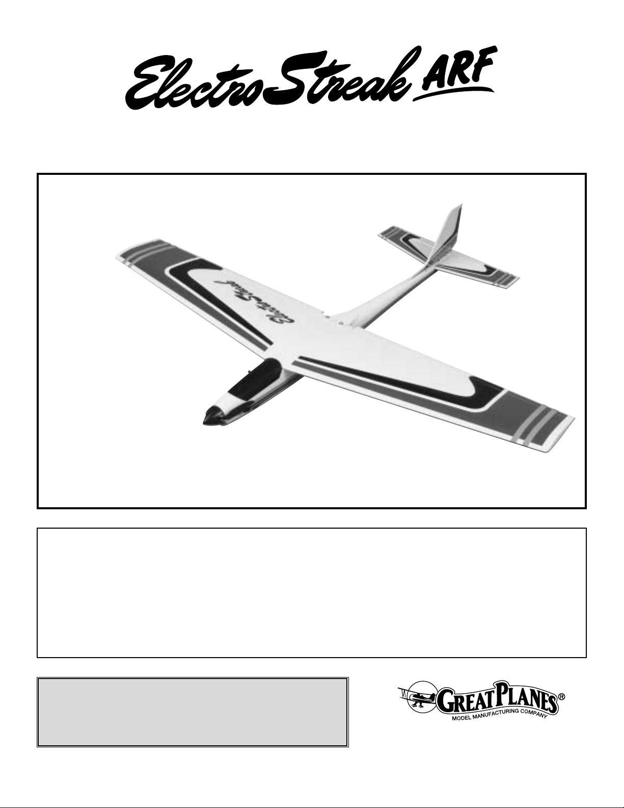
The ElectroStreak™ARF has been a favorite among pilots
since 1988. Many pilots began flying electrics with the
ElectroStreak. Over the years, there have been many
advancements in electronics such as high frequency
electronic speed controls and 3000mAh nickel-metal
hydride motor batteries. The original ElectroStreak was an
all wood kit.The ElectroStreak ARF comes as a high quality
fiberglass fuselage with a built-up wing and tail, motor,
folding prop and electronic speed control.You can be in the
air within hours after opening the box instead of spending
weeks or months building and covering the plane.
For the latest technical updates or manual corrections for
the ElectroStreak ARF, visit the web site listed below and
select the Great Planes ElectroStreak ARF. A “tech notice”
box will appear in the upper left corner of the page if there
is new technical information or changes to this kit.
http://www.greatplanes.com/airplanes/index.html
1.Your ElectroStreak ARF should not be considered a toy,
but rather a sophisticated, working model that functions
very much like a full-size airplane. Because of its
performance capabilities, the ElectroStreak ARF, if not
assembled and operated correctly, could possibly cause
injury to you or spectators and damage to property.
2. You must assemble the model according to the
instructions. Do not alter or modify the model, as doing so
may result in an unsafe or unflyable model. In a few cases
the instructions may differ slightly from the photos.In those
instances the written instructions should be considered as
correct.
3.You must take time to build straight, true and strong.
4. You must use an R/C radio system that is in first-class
condition with the appropriate size servos.
5.You must correctly install all R/C and other components
so that the model operates correctly on the ground and in
the air.
6.You must check the operation of the model before every
flight to insure that all equipment is operating and that the
model has remained structurally sound. Be sure to check
clevises or other connectors often and replace them if they
show any signs of wear or fatigue.
7. If you are not already an experienced R/C pilot, you
should fly the model only with the help of a competent,
experienced R/C pilot.
8.While this kit has been flight tested to exceed normal use,
if the plane will be used for extremely high stress flying,
such as racing, the modeler is responsible for taking steps
to reinforce the high stress points.
PRO TECT Y OUR MODEL,YOURSELF
& OTHERS...FOLLOW THESE
IMPORTANT SAFETY PRECAUTIONS
INTRODUCTION
TABLE OF CONTENTS
2
Page 3
Remember: Take your time and follow the instructions
to end up with a well-built model that is straight
and true.
If you have not flown this type of model before, we
recommend that you get the assistance of an experienced
pilot in your R/C club for your first flights. If you’re not a
member of a club, your local hobby shop has information
about clubs in your area whose membership includes
experienced pilots.
In addition to joining an R/C club, we strongly recommend
you join the AMA (Academy of Model Aeronautics). AMA
membership is required to fly at AMA sanctioned clubs.
There are over 2,500 AMA chartered clubs across the
country.
Among other benefits, the AMA provides insurance to its
members who fly at sanctioned sites and events.
Additionally, training programs and instructors are available
at AMA club sites to help you get started the right way .
Contact
the AMA at the address or toll-free phone number below:
Academy of Model Aeronautics
5151 East Memorial Drive
Muncie, IN 47302-9252
Tele. (800) 435-9262
Fax (765) 741-0057
Or via the Internet at: http://www.modelaircraft.org
This is a partial list of items required to finish the
ElectroStreak ARF that may require planning or decision
making before
starting to build.Order numbers are provided in
parentheses.
Radio Equipment
A 4-channel radio system with 3 micro servos is required.
Servos that measure 1" [25.4mm] long by 1" [25.4mm] high
by 1/2" [12.7mm] wide with at least 15 oz. of torque are
recommended. The Futaba®S3101 will work well in the
ElectroStreak ARF.Two 12" servo e xtensions are also
required
for the electronic speed control and the aileron servo.
Battery Selection
The ElectroStreak ARF was designed to fly on a 7-cell 8.4
volt 1700 – 3000 mAh flat battery pack. Even though the
ElectroStreak ARF will fly well on an inexpensive battery
pack, we recommend a battery pack that uses Sanyo
®
or
Panasonic®cells. These cells have a low internal resistance,
which translates into more power and less heat.
If you are new to electric airplanes, here is a short
explanation of rechargeable NiCd (Nickel Cadmium) and
NiMH (Nickel-Metal Hydride) batteries. A single cell
rechargeable battery supplies 1.2 volts with no load (not
powering anything). A 7-cell battery pack can supply 8.4
volts (1.2 volts x 7 cells = 8.4 volts). The cell rating in mAh
(milli-amp-hours) is the amount of current the battery can
supply. If a battery is rated at 1700 mAh, the battery can
supply 1.7 amps for 1 hour.This sounds great, flying for an
hour on a single battery charge! The bad news is that to
produce the power needed to fly an airplane the size of the
ElectroStreak ARF, the motor draws from 15-25 amps.The
current consumption reduces the run time to 4-8 minutes.
The good news is that propellers become more efficient as
the speed of the plane increases. This lowers the current
draw, allowing the plane to fly longer on a single charge,
sometimes up to 20% longer.Also, with an electronic speed
control, the motor can be throttled back, increasing the flight
time. Most airplanes only need full throttle during takeoff
and climbing maneuvers.
We recommend the use of high quality battery packs. The
higher quality batteries usually have less internal resistance
than the average battery. The higher quality battery will
provide more power to the motor than the average battery.
In rechargeable batteries, internal resistance transforms
power into heat.With less internal resistance, there is more
power av ailab le to the motor and less heat is generated.We
hope this helps explain NiCd and NiMH batteries and why a
high quality battery should be used in the ElectroStreak
ARF.
Chargers
A fully charged battery pack will provide an initial “surge” of
power during the first 15 to 30 seconds of the motor run.
Then the power output stays fairly steady for the next
several minutes before dropping off quickly. If you do not
charge your battery completely, it will not deliver that surge
necessary for a good takeoff and climb out.There are three
easy ways to “peak-charge” your battery pack.
1. The easiest way is with a “peak-detecting” battery
charger.This type of charger will automatically charge your
battery until it is fully charged.The NiMH batteries require a
peak-detecting charger that meets the specific charging
needs of NiMH batteries.
2.The second method of charging your motor batteries is to
monitor the voltage of your battery pack with a voltmeter.
This method is only recommended for NiCd batteries.
Your charger may have sockets into which you may plug a
voltmeter. If not, you may insert the probes from the
voltmeter into the rear of the battery plug, making contact
with the metal contacts. As your battery charges, the
voltage will gradually increase. When the battery is fully
charged, the voltage will start to drop. At this point your
battery is fully charged.
DECISIONS YOU MUST MAKE
We, as the kit manuf acturer , pro vide you with a top quality kit
and instructions, but ultimately the quality and flyability of
your finished model depends on how you build it; therefore,
we
cannot in any way guarantee the perf ormance of your
completed
model, and no representations are expressed or implied as
to the performance or safety of your completed model.
3
Page 4
3. The third (and least reliable) method of peak-charging
your battery pack is by checking its temperature. This
method is only recommended for NiCd batteries. As the
battery charges it will remain cool until it is fully charged.
When it reaches the fully charged state, it will rapidly build
up heat.You can feel this heat with your hand. As soon as
the pack starts to noticeably warm up, disconnect it from the
charger.Do not continue charging if the battery pack is
hot! Overcharging will damage your battery pack and can
result in an explosion.
IMPORTANT: The ESC and motor are a matched pair.
The use of a different ESC or motor may damage each
other and void their warranties.
In addition to common household tools and hobby tools, this
is the “short list” of the most important items required to
build the ElectroStreak ARF.
Great Planes Pro™CA and
Epoxy glue are recommended.
❏ 1/2 oz. Thin Pro CA (GPMR6001)
❏ 6-Minute epoxy (GPMR6045)
❏ 30-Minute epoxy (GPMR6047)
❏ Mixing sticks (GPMR8055)
❏ Great Planes Threadlocker
™
(GPMR6060)
❏ Hobby knife (HCAR0105)
❏ #11 Blades (HCAR0211)
❏ Builder’s triangle (HCAR0480)
❏ Electric drill and 1/16" [1.6mm], 3/32" [2.3mm], 1/8"
[3.1mm], 1/4" [6.4mm] drill bits
❏ Small phillips screwdrivers
❏ Pliers with wire cutter (HCAR0630)
❏ 6-Piece standard ballwrench set (GPMR8008)
❏ Masking tape (TOPR8018)
❏ Denatured alcohol (for epoxy clean up)
Here is a list of optional tools mentioned in the manual that
will help you build the ElectroStreak ARF.
❏ Great Planes CG Machine
™
(GPMR2400)
❏ Straightedge with scale (HCAR0475)
❏ CA Debonder (GPMR6039)
❏ CA Applicator tips (GPMR6033)
❏ Non-elastic monofilament or Kevlar
™
fishing line (for
stab alignment)
❏ Felt-tip marker (TOPQ2510)
❏ Great Planes AccuThrow
™
Deflection Gauge (for
measuring control throws, GPMR2405)
❏ Soldering iron (25 watt)
• There are two types of screws used in this kit:
Sheet metal screws are designated by a number and a
length. For example #6 x 3/4" [19mm].
This is a number six screw that is 3/4" [19mm] long.
Machine screws are designated by a number, threads per
inch, and a length. For example 4-40 x 3/4" [19mm].
This is a number four screw that is 3/4" [19mm] long with
forty threads per inch.
• When you see the term
test fit
in the instructions, it means
that you should first position the part on the assembly
without using any glue, then slightly modify or
custom fit
the part as necessar y for the best fit.
• Whenever the term
glue
is written you should rely upon
your experience to decide what type of glue to use.When a
specific type of adhesive works best for that step, the
instructions will make a recommendation.
• Whenever just
epoxy
is specified you may use
either
30-minute (or45-minute) epoxy or6-minute epoxy. When
30-minute epoxy is specified it is highly recommended that
you use only 30-minute (or 45-minute) epoxy, because you
will need the working time and/or the additional strength.
• Photos and sketches are placed before the step they
refer to. Frequently you can study photos in following steps
to get another view of the same parts.
• The Great Planes ElectroStreak ARF is factory-covered
with Top Flite®MonoKote®film. Should repairs ever be
required, MonoKote can be patched with additional
MonoKote purchased separately. MonoKote is packaged in
six-foot rolls, but some hobby shops also sell it by the foot.
If only a small piece of MonoKote is needed for a minor
patch, perhaps a fellow modeler would give you some.
MonoKote is applied with a model airplane covering iron, but
in an emergency a regular iron could be used. A roll of
MonoKote includes full instructions for application.Following
are the colors used on this model and order numbers for six
foot rolls.
White TOPQ0204
Dove Gray TOPQ0211
Sapphire Blue TOPQ0226
Black TOPQ0208
IMPORTANT BUILDING NOTES
Optional Supplies & Tools
Adhesives & Building Supplies
ADDITIONAL ITEMS REQUIRED
4
Page 5
5
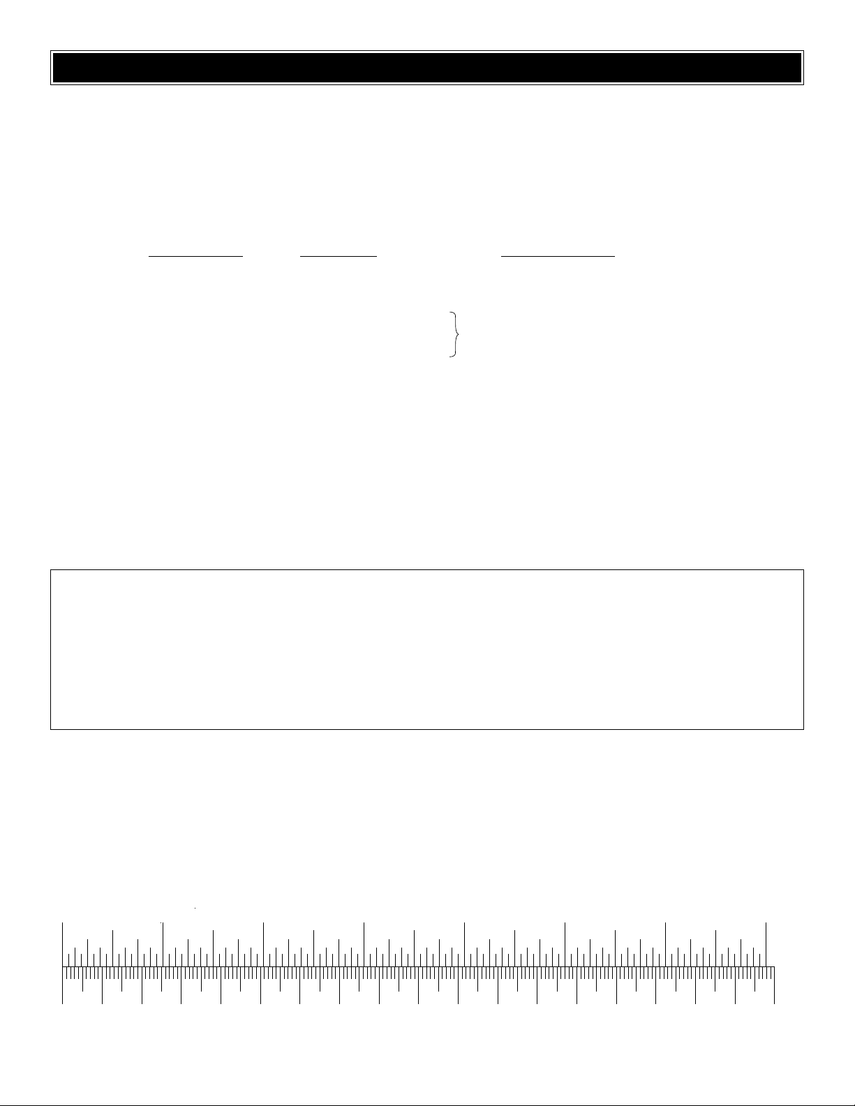
0" 1" 2" 3" 4" 5" 6" 7"
0 10 20 30 40 50 60 70 80 90 100 110 120 130 140 150 160 170 180
Inch Scale
Metric Scale
ORDERING REPLACEMENT PARTS
To order replacement parts for the Great Planes ElectroStreak ARF, use the order numbers in the Replacement Parts List
that follows. Replacement parts are available only as listed. Not all parts are available separately (an aileron cannot be
purchased separately, but is only available with the wing kit). Replacement parts are not available from Product Support,
but can be purchased from hobby shops or mail order/Internet order firms. Hardware items (screws, nuts, bolts)
are also
available from these outlets .If you need assistance locating a dealer to purchase parts, visit
www.greatplanes.com and click
on “Where to Buy.” If this kit is missing parts, contact Great Planes Product Support.
Replacement Parts List
Order Number Description Ho
w to Purchase
Missing pieces............................Contact Product Suppor t
Instruction manual......................Contact Product Support
Full-size plans............................Not available
GPMA2261 ........................Wing Set
GPMA2260 ........................Fuse Set
GPMA2262 ........................Tail Set
1/64" = .4 mm
1/32" = .8 mm
1/16" = 1.6 mm
3/32" = 2.4 mm
1/8" = 3.2 mm
5/32" = 4.0 mm
3/16" = 4.8 mm
1/4" = 6.4 mm
3/8" = 9.5 mm
1/2" = 12.7 mm
5/8" = 15.9 mm
3/4" = 19.0 mm
1" = 25.4 mm
2" = 50.8 mm
3" = 76.2 mm
6" = 152.4 mm
12" = 304.8 mm
18" = 457.2 mm
21" = 533.4 mm
24" = 609.6 mm
30" = 762.0 mm
36" = 914.4 mm
Metric Conversions
Contact Your Hobby
Supplier To Purchase
These Items
Page 6
6
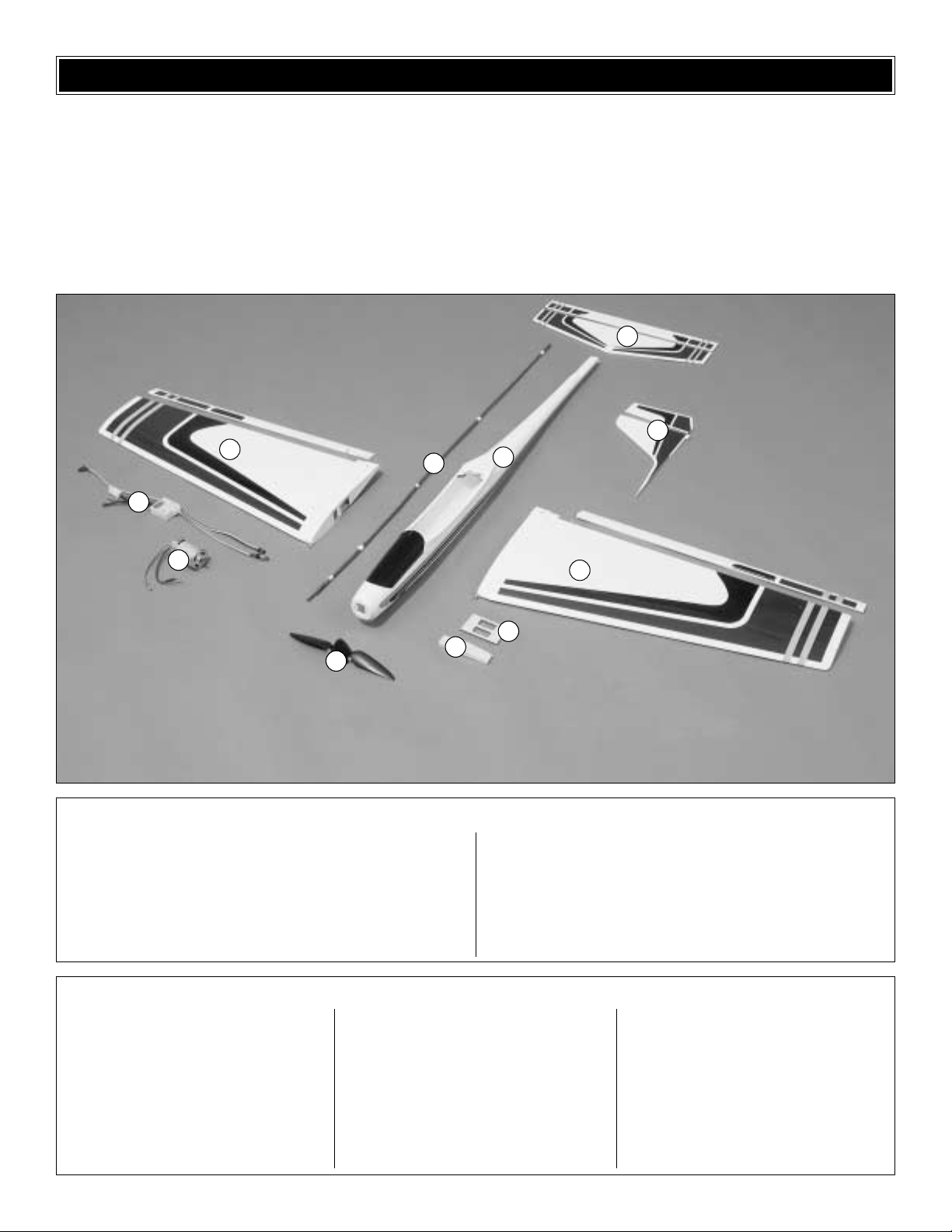
KIT CONTENTS
Before starting to build, use the Kit Contents list to take an inventory of this kit to make sure it is complete, and inspect
the parts to make sure they are of acceptable quality. If any parts are missing or are not of acceptable quality, or if you need
assistance with assembly, contact Great Planes Product Support. When reporting defective or missing parts, use the part
names exactly as they are written in the Kit Contents list on this page.
Great Planes Product Support:
Phone: (217) 398-8970
Fax: (217) 398-7721
E-mail: airsupport@greatplanes.com
1. R & L Wing Panels w/Ailerons
2. Fuselage
3. Stab w/Elevator
4. Fin w/Rudder
5. Folding Propeller w/Spinner
6. Motor
7. Electronic Speed Control
8. Wing Joiner
9. Servo Tra y
10. Pushrods
(1) Battery Tray
(1) Aileron Servo Tray
(2) Aileron Servo Tray Base
(1) Elevator Outer Pushrod Forward Support
(2) Hook and Loop Material
(2) 1.5mm Set Screw
(1) 1.5mm Hex Wrench
(2) 1.5mm x 8mm Sheet Metal Screw
(2) 1110mm Pull/Pull Cable
(2) 2-56 Cable-To-Clevis Connector
(4) 2-56 x 5/8" Machine Screw
(2) 6-32 x 3/4" Machine Screw
(2) #6 Washer
(2) Screw-Lock Pushrod Connector Body
(2) 4-40 x 1/4" Socket Head Cap Screw
(2) 3mm x 10mm Machine Screw
(2) 3mm Washer
(12) CA Hinges
(5) Nylon Clevis
(2) 2mm Torque Rod Horn
(2) Screw-Lock Pushrod Connector Retainer
(2) 2-56 x 6" Pushrod Threaded One End
(2) Crimp Fitting
(1) 6-1/2" White Inner Flex Tube
(2) #2 x 3/8" Sheet Metal Screw
1
1
5
2
3
4
7
8
6
10
9
Kit Contents (Photographed)
Kit Contents (Not Photographed)
Page 7
❏ 1. If you have not done so already, remove the major
parts of the kit from the box (wing halves, fuselage, tail
parts, etc.) and inspect them for damage. If any par ts are
damaged or missing, contact Product Support at the
address or telephone number listed on the front cover.
❏ 2. Remove the masking tape and separate the ailerons
from the wing, the rudder from the fin and the elevator from
the stabilizer.With a covering sock on y our cov ering iron, set
the temperature to high and tighten the covering, if
necessary .Apply pressure over sheeted areas to
thoroughly
bond the covering to the wood. Hint: Poke three or four pin
holes in the covering between the “ribs” in the tail surfaces.
This will allow the hot air to escape while tightening the
covering.
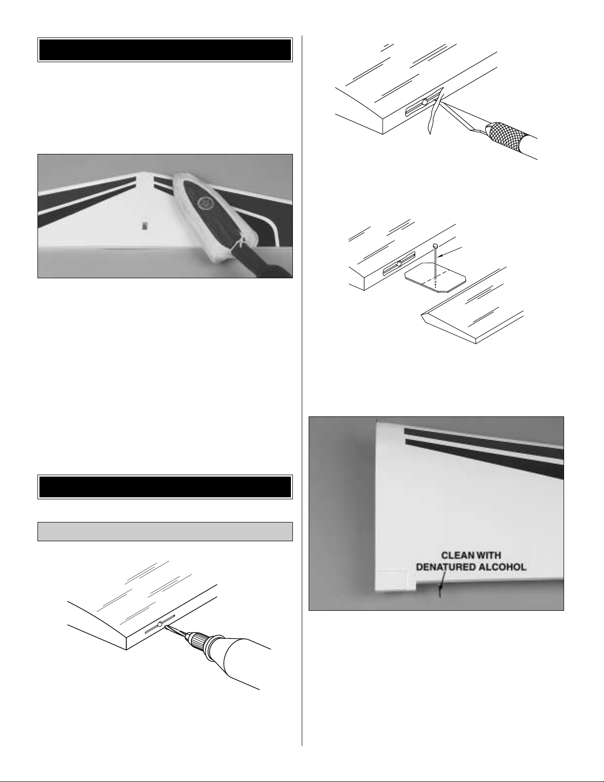
❏ ❏ 1. Drill a 3/32" [2.3mm] hole, 1/2" [12.7mm] deep in
the center of each hinge slot to allow the CA to “wick” in.
Follow-up with a #11 blade to clean-out the slots. Hint: If
you have one , use a high-speed rotary tool to drill the holes.
❏ ❏ 2. Use a sharp #11 blade to cut a strip of covering
from the hinge slots in the wing and aileron.
❏ ❏ 3. Test fit the ailerons to the wing with the hinges. If
the hinges don’t stay centered, stick a pin through the
middle of the hinge to hold it in position.
❏ ❏ 4.Clean the aileron torque rod with denatured alcohol
to remove any contaminants.
❏ ❏ 5. Mix up a small amount of 6-minute epoxy. Using a
toothpick, apply epoxy in the aileron torque rod hole and
along the groove in the leading edge of the aileron. Before
the epoxy cures, install the aileron on the wing.Remove any
pins you may have inserted into the hinges. Adjust the
aileron so there is a small gap between the LE of the aileron
and the wing.The gap should be small – just enough to see
light through or to slip a piece of paper through.
TEMPORARY PIN
TO KEEP HINGE
CENTERED
AWAY FROM THE SLOT
CUT THE COVERING
DRILL A 3/32" HOLE
1/2" DEEP, IN CENTER
OF HINGE SLOT
Install the Ailerons
BUILD THE WING
PREPARATIONS
7
Page 8

❏ ❏ 6. Apply six drops of thin CA to the top and bottom of
each hinge. Do not use CA accelerator. After the CA and
epoxy have fully hardened, test the hinges by pulling on the
aileron.
❏ 7. Go back to step 1 and repeat the hinge installation for
the other aileron.
❏ 1. The wing joiner has a top and a bottom. To deter mine
which is the top, place the wing joiner on a flat surface and
note the gap between the joiner and the flat surface.The
side
with the smallest gap is the top.Mark top on the wing joiner.
❏ 2. Test fit the wing halves together with the wing joiner.
Make sure the wing joiner is installed correctly. If it is not, the
root of the wings will not fit together correctly. If the wing
joiner needs to be sanded so that it will fit in the wing, sand
the bottom of the joiner.The top of the wing should be flat
when both wing halves are joined.
❏ 3. Prepare 1/2 oz. of 30-minute epoxy. Working quickly,
thoroughly coat the inside of both wing halves where the
joiner fits and one half of the joiner with epoxy. Making
certain the joiner is upright, inser t the coated end into one
of the wing halves. Coat the other end of the joiner and the
root ribs with the remainder of the epoxy. Join the wing
halves tightly, holding them together. Use a paper towel
dampened with denatured alcohol to wipe away the excess
epoxy that comes out of the wing. Tightly hold the wing
together with masking tape, making certain both halves are
in full contact and the leading and trailing edges are aligned.
Let the wing set until the epoxy has cured.
Join the Wing
8
Page 9

❏ 4. Glue the two aileron servo tray bases and the servo
tray in the center of the wing. Note: The two bases should
straddle the root ribs.
❏ 1. Inspect the blind nuts that are pressed into the bottom
of the wing nut plate inside the fuselage. If the nuts are not
securely pressed into the plate, remove them. Apply a dab
of 30-minute epoxy to the flange around the blind nuts, then
reinsert them into the plate. Do not get any epoxy into the
threads. Use a 6-32 x 3/4" machine screw and a #6 washer
to draw the blind nut all the way up into the wood by
tightening the bolt to the top of the plate.
❏ 2. Remove the covering from over the two bolt holes at
the trailing edge of the wing.
❏ 3.Test fit the wing to the fuselage and bolt it into position
with two 6-32 x 3/4" machine screws and two #6 washers. If
necessary, enlarge or adjust the wing bolt holes in the wing
so the wing bolts will align with the blind nuts.
❏ 1. Fit the stab onto the fuselage. Center the trailing edge
of the stab on the aft end of the fuselage. A clothespin
placed over the stab and fuselage works great for holding
the stab in position.
❏ 2. Stick a T-pin into the center of the top of the wing, at
the leading edge. Tie a small loop in one end of a 36"
[914mm] piece of non-elastic string such as K&S #801
Kevlar thread (K+SR4575). Slip the loop in the string over
the T-pin.
Mount the Stab & Fin
Mount the Wing
ASSEMBLE THE FUSELAGE
9
Page 10

❏ 3. Fold a piece of masking tape over the other end of the
string and draw an arrow on it. Slide the tape along the
string and align the arrow with one end of the stab. Swing
the string over the same position on the other end of the
stab.While keeping the trailing edge of the stab centered on
the fuselage, adjust the stab and slide the tape along the
string until the arrow aligns with both ends of the stab. Be
certain the trailing edge of the stab remains centered on the
aft end of the fuselage.
❏ 4. Use a fine-point felt-tip pen such as a Top Flite Panel
Line Pen (TOPQ2510) to mark the outline of the fuselage
onto the bottom of the stab.
❏ 5. Remove the stab from the fuselage. Use a sharp #11
hobby knife or use the Expert Tip that follows to cut the
covering from the stab along the lines you marked.Use care
to cut only the covering and not into the wood.
❏ 6. The same as you did for the wing and aileron, cut the
covering from the hinge slots in the stab/elevator and
fin/rudder.There are four hinge slots in the stab/elev ator and
two in the fin/rudder. Drill a 3/32" [2.3mm] hole through the
center of each hinge slot.
❏ 7. Lightly sand the top of the stab saddle, on the
fuselage, to remove the shine. Clean the surface with
rubbing alcohol. This will allow the epoxy to make a secure
bond to the fiberglass fuselage.
❏ 8. Using 30-minute epoxy, glue the stab to the fuselage.
Apply a light coat of epoxy to the stab saddle and to the
bottom of the stab. Position the stab on the fuselage. Make
sure the stab is centered on fuselage.Use the string method
to align the stab on the fuse. Use clamps or weights to hold
the stab against the fuselage. Wipe off the excess epoxy
with a paper towel dampened with rubbing alcohol.
❏ 9.With the plane setting in a plane stand, view the plane
5' to 10' from the rear.Check that the stab is parallel to the
How to cut covering from balsa
Use a 25 watt soldering iron to cut the covering from the
stab. The tip of the soldering iron doesn’t have to be
sharp, but a fine tip does work best.Allow the iron to heat
fully.Use a metal straightedge to guide the soldering iron
at a rate that will just melt the covering and not burn into
the wood.The hotter the soldering iron, the faster it must
travel to melt a fine cut. Allow the heat to melt the
covering.Do not apply a lot of pressure or the wood may
be damaged. Peel off the covering.
10
Page 11

wing. If it is not, the following Expert Tip can be used to
slightly twist the fuselage.
❏ 10. Use a 1/8" drill bit to dr ill two rudder cable exit holes
at the front of the indentations, at the aft end of the fuselage.
❏ 11. Cut two 1-1/2" [38mm] long cable guide tubes from
the 6-1/2" [165mm] white plastic tube. Glue the cable guide
tubes in the holes drilled in the previous step. Allow the
tubes to extend out of the holes approximately 1/8" [3mm].
❏ 12. Fit the fin into the stab.From the aft end of the plane,
sight down the fin, checking that it is aligned with the
centerline of the fuselage. Mar k the outline of the fin on the
stab. Then use the soldering iron technique to remove the
covering on the stab.Glue the fin into position using 30-
minute
epoxy. Use a builder’s square to make sure the fin is
perpendicular to the stab.Masking tape can be used to hold
the fin in position until the epoxy cures.
❏ 1. Install the r udder and elevator servos in the servo tray
using the hardware that is included with the servos.You may
need to trim the servo mounting holes to accommodate the
brand of micro servos you are using.Note that the servo tra y
has a wide side and a narrow side and which direction the
servos face compared to the sides.
❏ 2. Position the servo tray in front of the wing nut plate so
that the narrow end is towards the aft end of the plane.Make
sure that you can get to the servo mounting screws.If there
is space between the rudder and elevator servos and the
bottom of the fuselage, we recommend that you use a
sanding bar to sand a bevel on the sides of the servo tray to
allow the tray to set lower. This will leave more room
between the elevator and rudder servos and the aileron
Install Servo & Battery Tray
Straightening a twisted fiberglass fuselage
Use a heat gun to heat the fuselage between the stab
and wing.Try to heat the fuselage evenly.Do not hold the
heat gun in one place.It does not require a lot of heat;the
fuse needs to be warm. Hold the fuselage in front of the
wing and in front of the stab and gently twist. Hold the
fuselage in this position until it has cooled.You may need
to twist it a few times before you get it in the correct
position.
11
Page 12

torque rods.When satisfied with the fit, use 6-minute epoxy
to glue the servo tray to the fuselage sides.
❏ 3. Use a servo arm that has a pushrod mounting hole
approximately 7/16" [11mm] out from the center of the arm
for the elevator servo.Trim the servo arm so that only one
arm remains.
❏ 4. Cut the gray outer pushrod 20" [508mm] long. Sand
the outside of the tube with 320-grit sandpaper and wipe it
off with a paper towel dampened with rubbing alcohol.
❏ 5. Inser t the outer pushrod tube from the aft end of the
fuselage. The forward end of the pushrod should be even
with the aft edge of the wing saddle.Glue the outer pushrod
to the aft brace, pre-installed in the aft end of the fuselage,
by holding the fuselage with its nose down and dripping a
couple of drops of CA onto the joint between the outer
pushrod and aft brace.
❏ 6. Cut the 36" [914mm], threaded on one end pushrod
25" [635mm] long, measured from the threaded end.
❏ 7. From the remaining white tube, cut four 1/4" [6.3mm]
long pushrod guides. Slide the four guides onto the 25"
[635mm] pushrod. The first guide should be positioned
approximately 4-1/2" [114mm] from the threaded end.
Space the remaining three 4-1/2" [114mm] apart. Glue the
guides to the pushrod with a drop of thin CA.
❏ 8.Insert the non threaded end of the pushrod in the outer
pushrod tube. Align the end of the pushrod with the hole in
the servo horn, 7/16" from the center of the servo horn. Use
6-minute epoxy to glue the forward pushrod tube brace to
the inside of the fuselage, on the right side. The slot in the
brace will allow you to adjust the position of the outer
pushrod
tube so that it is straight before gluing it to the brace.
❏ 9. Use 6-minute epoxy to glue the battery tray in the
bottom of the fuselage. The tray should be centered
between the servo tray and the front of the wing saddle.
❏ 1. Insert the motor through the wing opening and align
the screw holes in the motor with the holes in the front of the
Install the Motor & Speed Control
12
Page 13

fuselage. Attach the motor to the fuselage using two 3mm x
10mm machine screws and 3mm washers.
❏ 2. Cut a 7/16" x 1/4" [11mm x 6mm] hole for the speed
control on/off switch in the side of the fuselage,
approximately 5" [127mm] from the front of the fuselage.We
suggest first drawing the rectangle on the side of the
fuselage.Then, use a 3/32" [2.3mm] drill bit to drill a hole in
each corner of the rectangle.
❏ 3. Use a sharp hobby knife to cut the remainder of the
rectangle.
❏ 4. Drill a 1/4" [6mm] hole, 3/4" [19mm] forward of the
on/off rectangle.T est fit the motor b utton in the hole from the
outside to check the fit.You may need to enlarge the hole
slightly with a hobby knife.
❏ 5.Remove the nut and split washer from the motor button
and install the button from the inside. Secure the button to
the fuselage with the split washer and nut. Inser t the on/off
switch, end first, from the inside, through the hole in the
fuselage. Carefully pull the switch through the hole, making
sure not to damage the wires. Secure the switch to the
fuselage with two #2 x 3/8" sheet metal screws.
❏ 6. Plug the electronic speed control into the motor.The
red wire from the speed control must plug into the red wire
from the motor and the black into the black. Check that the
insulation covers the metal connectors on both plugs. If it
does not, use electrical tape to insulate the plugs to prevent
them from shorting.
❏ 7. From the hook and loop material, cut a 1-1/2" [38mm]
long piece of both material. Clean the back of the electronic
speed control with a paper towel dampened with rubbing
alcohol. Glue the soft material to the back of the electronic
speed control with CA. Glue the rough material to the inside
of the fuselage, opposite the on/off switch. Attach the
electronic speed control to the side of the fuselage.
❏ 1.Temporarily attach the elev ator to the stab with f our CA
hinges. Do not glue the hinges. Thread a nylon clevis onto
the elevator pushrod, 14 turns, and slide a silicone clevis
retainer over the clevis. Attach the clevis in the third hole
from the bottom of a small control horn and insert the
pushrod in the outer pushrod tube, in the fuselage.
❏ 2.Align the clevis attachment holes with the leading edge
of the elevator and center the control horn on the aft end of
the fuselage. Mark on the elevator the location of the two
control horn mounting holes.
Install the Elevator
13
Page 14
❏ 3. Remove the elevator from the stab. Dr ill 3/32" holes
through the elevator, at the mar ks. Mount the control horn
with two 2-56 x 5/8" machine screws and the nylon
mounting plate on the other side of the elevator. Cut off the
excess screws.
❏ 4. Re-install the elevator on the stab and glue the hinges
with CA. Attach the clevis to the control horn.
❏ ❏ 1.Slide a crimp fitting on one end of the rudder cable.
Insert the cable through the bottom hole in the threaded
cable connector and back through the crimp fitting. Crimp
the fitting down tightly on the cable.
❏ ❏ 2. Thread a nylon clevis 14 turns onto the threaded
cable connector .Install a silicone clevis retainer on the
clevis.
❏ 3. Repeat steps one and two to assemble a second
rudder cable.
❏ 4. Insert the two rudder cables in the exits on top of the
fuselage.
❏ 5. Temporarily attach the rudder to the fin. Do not glue
the hinges.Attach the left side clevis in the second hole from
the bottom of a small control horn.
❏ 6.Position the control horn on the rudder so that the horn
is approximately 5/8" [16mm] from the bottom of the rudder
and the clevis attachment holes are aligned with the leading
edge of the rudder. Mark on the rudder, the control horn
mounting holes.
❏ 7. Remove the rudder and drill a 3/32" [2.3mm] hole
through the rudder at both marks.
❏ 8. Mar k the left rudder control horn with an “L.” Remove
the control horn from the clevis and tack glue, back-to-back,
a second control horn to the left control horn. Drill a 1/16"
[1.5mm] hole through both control horn mounting holes in
the left control horn.
❏ 9.Attach the left and right control horns to the rudder with
two 2-56 x 5/8" machine screws.Trim off the excess scre ws .
❏ 10. Re-install the rudder on the fin and glue the CA
hinges with thin CA.
❏ 11. Attach the clevises in the second hole of each of the
control horns.
Install the Rudder
14
Page 15

❏ 1. We recommend that the receiver be installed behind
the servo tray. This will allow the motor battery to be moved
forward and aft to adjust the balance point (C.G.) later.Plug
the rudder and elevator servos, and the electronic speed
control into the receiver, with a 12" [305mm] servo lead
extension and a 12" [305mm] aileron servo lead extension.
The receiver can be secured to the bottom of the fuselage
with a 1" [25mm] piece of hook and loop material cut from
the second strip of material.
❏ 2. To secure the connection between the electronic
speed control lead and the servo extension, wrap a piece of
electrical tape or shrink tubing around the plugs. This can
then be attached to the inside of the fuselage with CA,
keeping it clear of the motor battery.
❏ 3. Plug the motor battery into the electronic speed
control. Switch on the transmitter, then the speed control.
Center the elevator and rudder servo trim on your
transmitter.If needed, remove the rudder and elevator servo
arms and center them.
❏ 4. Center the elevator and mark where the elevator
pushrod crosses the elevator servo arm. Make a 90° bend
at the mark. Cut the pushrod 3/8" [9.5mm] past the bend.
Attach the pushrod to the servo arm with a Faslink.
❏ 5. Trim a servo arm so that it has two arms, opposite
each other, with the outer holes appro ximately 7/16" [11mm]
from the center.
❏ 6. Install a screw-lock pushrod connector in both of the
holes 7/16" [11mm] from the center. Use the screw-lock
pushrod connector to secure them to the servo arm. Center
the servo arm on the rudder ser vo.
❏ 7. Insert the pull-pull cables through the screw-lock
pushrod connectors. Check that the cables are not twisted
inside the fuselage.
❏ 8. With the rudder centered, secure the cables in the
screw-lock pushrod connectors with 4-40 x 1/4" sock et head
cap screws.The cables should be tight, but not so tight that
they put a strain on the servo.Cut off the excess cable.
❏ 9. Install the aileron servo in the aileron tray. Install a
servo horn with two arms and holes 7/16" [11mm] from the
center of the arm.
RADIO SET-UP
15
Page 16

❏ 10. Thread the two nylon torque rod horns onto the
aileron torque rods. The bottom of the horn should be
approximately 1/2" [13mm] from the wing.
❏ 11.Thread a nylon clevis 14 turns onto the end of the two
2-56 x 6" aileron pushrods. Slide a silicone retainer over
both clevises.Attach the clevises to the torque rod horns.
❏ 12. With the aileron servo and ailerons centered, mark
the aileron pushrods where they cross the aileron servo
arm.Make a 90° bend at the marks and cut the pushrod 3/8"
[9.5mm] past the bend. Attach the pushrods to the aileron
servo arm with nylon Faslinks.Cut off the excess threads on
the aileron torque rods.
❏ 1. Note that the aluminum propeller hub has two holes
that are recessed. These holes are to the back of the
spinner.
❏ 2. Attach the propeller blades to the hub with two 5/64" x
3/8" [1.9mm x 9.5mm] pins. Check that the blades move
freely.If they do not, lightly sand the root of each blade until
they do.
❏ 3.Thread the two 1.5mm set screws into the aluminum
hub.
❏ 4. Insert the aluminum hub in the back of the spinner.
Secure the spinner to the hub with two 1.5mm x 8mm sheet
metal screws.
❏ 5. Attach the spinner to the motor shaft. One of the set
screws must tighten down on the flat of the motor shaft.If it
does not, the prop may come off of the motor shaft. Check
that both set screws are tight.
❏ 1. Insert the rough hook-and-loop mater ial, rough side
down, under the battery tray.
Battery Installation
ASSEMBLE & INSTALL THE
FOLDING PROPELLER
16
Page 17

❏ 2. Position the motor battery on the tray. Attach the soft
hook-and-loop material to the rough material to secure the
battery in place.
❏ 1.Switch on the transmitter, connect the motor battery to
the electronic speed control and switch on the speed
control.
❏ 2. With the transmitter and receiver on, check all the
control surfaces to see if they are centered. If necessary,
adjust the clevises on the pushrods to center the control
surfaces.
❏ 3. Make certain that the control surfaces respond in the
correct direction as shown in the diagram. If any of the
controls respond in the wrong direction, use the servo
reversing in the transmitter to reverse the servos connected
to those controls. Be certain the control surfaces have
remained centered. Adjust if necessar y.
Use a Great Planes AccuThrow (or a ruler) to accurately
measure and set the control throw of each control surface
as indicated in the chart that follows. If your radio does not
have dual rates, we recommend setting the throws at the
low rate setting.
Note: The throws are measured at the widest par t of the
elevators, rudder and ailerons.
IMPORTANT: The ElectroStreak ARF has been
extensively flown and tested to arrive at the throws at
which it flies best. Flying your model at these throws will
provide you with the greatest chance for successful first
flights. If, after you have become accustomed to the way
the ElectroStreak ARF flies, and you would like to change
the throws to suit your taste, this is fine. However, too
much control throw could make the model difficult to
control, so remember, “More is not always better.”
These are the recommended control surface throws:
High Rate Low Rate
ELEVATOR: 1/2" [13mm] up 3/8" [9.5mm] up
3/8" [9.5mm] down 5/16" [8mm] down
RUDDER: 1-1/4" [32mm] right 1" [25mm] right
1-1/4" [32mm] left 1" [25mm] left
AILERONS: 3/16" [5mm] up 1/8" [3mm] up
3/16" [5mm] down 1/8" [3mm] down
Set the Control Throws
Check the Control Directions
GET THE MODEL READY TO FLY
17
4-CHANNEL
TRANSMITTER
4-CHANNEL
TRANSMITTER
4-CHANNEL
TRANSMITTER
4-CHANNEL
TRANSMITTER
Page 18

At this stage the model should be in ready-to-fly condition
with all of the systems in place including the motor, prop,
electronic speed control, motor battery and the radio
system.
❏ 1. Use a felt-tip pen or 1/8"-wide tape to accurately mark
the C.G. on the bottom of the wing on both sides of the
fuselage.The C.G.is located 3-9/16" [90mm] back from the
leading edge of the wing.
❏ 2.With the wing attached to the fuselage, and all parts of
the model installed (ready to fly), place the model right side
up on a Great Planes CG Machine, or lift it right side up at
the balance point you marked.
❏ 3.When the ElectroStreak ARF is properly balanced, the
stab will be level. If the tail drops, the model is “tail heavy”
and the motor battery must be shifted forward or weight
must be added to the nose to balance.If the nose drops, the
model is “nose heavy”and the motor battery must be shifted
aft or weight must be added to the tail to balance.If possible,
relocate the motor battery to minimize or eliminate any
additional weight required. If additional weight is required,
use Great Planes (GPMQ4485) “stick-on” lead. A good
place to add stick-on nose weight is inside the front of the
fuselage. Begin by placing incrementally increasing
amounts of weight in the fuse until the model balances.
Once you have determined the amount of weight required,
it can be permanently attached. If required, tail weight may
be added to the inside of the aft end of the fuselage. Make
sure the tail weight does not interfere with the movement of
the elevator pushrod.
If moving the motor battery forward or aft will balance the
plane without adding additional weight, mark the battery
tray or the fuselage inside where the aft end of the battery
should be placed.This will allow you to position the battery
correctly before each flight.
❏
4. IMPORTANT: If you found it necessary to add any
weight, recheck the C.G.after the weight has been installed.
❏ 1. With the wing level, have an assistant help you lift the
model by the motor shaft and the bottom of the fuse under
the TE of the fin.Do this several times.
❏ 2. If one wing always drops when you lift the model, it
means that side is heavy. Balance the airplane by adding
weight to the other wing tip. An airplane that has been
laterally balanced will track better in loops and other
maneuvers.
No matter if you fly at an AMA sanctioned R/C club site or
if you fly somewhere on your own, you should always have
your name, address, telephone number and AMA number
on or inside your model. It is required at all AMA R/C club
flying sites and AMA sanctioned flying events. Fill out the
identification tag on page 21 and place it on or inside
your model.
Identify Y our Model
PREFLIGHT
Balance the Model Laterally
This is where your model should balance for your first
flights. Later, you may wish to experiment by shifting the
C.G. up to 3/16" [5mm] forward or 3/16" [5mm] back to
change the flying characteristics. Moving the C.G.
forward
may improve the smoothness and stability, but it may
then require more speed for hand launch and make it
more difficult to slow for landing. Moving the C.G. aft
makes the model more maneuverable, but could also
cause it to become too difficult for you to control. In any
case, start at the location we recommend and do not at
any
time balance your model outside the recommended
range.
More than any other factor, the C.G. (balance point) can
have the greatest effect on how a model flies, and may
determine whether or not your first flight will be
successful.If you value this model and wish to enjoy it for
many flights, DO NOT OVERLOOK THIS IMPORTANT
PROCEDURE. A model that is not properly balanced will
be unstable and possibly unflyable.
Balance the Model (C.G.)
18
Page 19

Follow the battery charging instructions that came with your
radio control system to charge the transmitter. You should
always charge your transmitter batteries the night before
you go flying, and at other times as recommended by the
radio manufacturer.
❏ 1. The included motor will benefit from a shor t “break-in”
by running the motor without the propeller for at least 15
minutes. This will seat the motor brushes on the
commutator, insuring that the motor will provide full power
for your first flight and extend the life of your motor. If you
notice a decrease in motor power after sev eral flights , it ma y
be due to carbon build-up on the brushes or commutator.To
remove this build-up, repeat the above break-in procedure.
❏ 2.The bronze bushings in the motors are self-lubricating,
but their life may be extended by applying a very small
amount of light machine oil to the point where the motor
shaft contacts the bushings after every hour or two of run
time. Note: A drop of oil is far too much.You should apply
the oil with a toothpick. Never oil the inside of the motor.
❏ 3. Using multiple battery packs to run the motor for
successive flights may cause the motor to become
excessively
hot. We recommend at least a 10-minute cool-down period
between flights.
❏ 4.The ideal power source for the ElectroStreak ARF is a
7-
cell, 8.4 volt 1700 – 3000 mAh battery pack.The use of a
higher voltage battery may reduce the motor life and
damage the electronic speed control.
❏ 1. A new battery pack should be “cycled” for best results.
You should peak charge the battery, then discharge it
almost completely by actually running your motor with the
propeller attached.Do this 2 or 3 times on the ground before
actually flying. Be sure you remove the battery from the
airplane between each cycle and allow it and the motor to
cool before recharging.
❏ 2.The standard Tamiya battery connectors supplied with
your electronic speed control and motor battery are
adequate for most installations. However, if you are looking
for maximum performance, you may want to consider
installing high-performance battery connectors such as
DuraTrax®Powerpole™connectors (DTXC2300).
❏ 3. Examine your propeller for irregularities caused by the
injection molding process. Carefully remove the
imperfections
with fine sandpaper.
After you break-in the motor on the model, inspect the
model closely to make sure all screws remained tight, the
hinges are secure, the prop is secure and all pushrods and
connectors are secure.
Whenever you go to the flying field, check the operational
range of the radio before the first flight of the day. First,
make sure no one else is on your frequency (channel).Have
an assistant hold the model, staying clear of the prop.With
your transmitter on, you should be able to walk at least 100
feet away from the model and still have control. While you
work the controls, have your assistant tell you what the
control surfaces are doing. Repeat this test with the motor
running at various speeds. If the control surfaces are not
always responding correctly, do not fly! Find and correct the
problem first.Look for loose servo connections or corrosion,
loose bolts that may cause vibration, a defective on/off
switch, low battery voltage, a damaged receiv er antenna, or
a receiver crystal that may have been damaged from a
previous crash. If the radio appears to only be affected
when the motor is running, try moving your receiver and
receiver antenna farther away from the motor battery and
motor.Also, installing a couple more capacitors on the
motor
may help.The capacitors should be soldered from the
terminals
to the motor case, and from one terminal to the other.
Read and abide by the following Academy of Model
Aeronautics Official Safety Code:
GENERAL
1. I will not fly my model aircraft in sanctioned events, air
shows, or model flying demonstrations until it has been
proven to be airworthy by having been previously
successfully flight tested.
2. I will not fly my model aircraft higher than approximately
400 feet within 3 miles of an airport without notifying the
airport operator.I will give right of way to, and avoid flying in
the proximity of full-scale aircraft. Where necessary an
observer shall be used to supervise flying to avoid having
models fly in the proximity of full-scale aircraft.
3.Where established, I will abide by the safety rules for the
flying site I use, and I will not willfully and deliberately fly my
models in a careless, reckless and/or dangerous manner.
7. I will not fly my model unless it is identified with my name
and address or AMA number, on or in the model.
AMA SAFETY CODE (excerpt)
Range Check
Ground Check
PERFORMANCE TIPS
PROPER CARE OF YOUR MOTOR
Charge the Batteries
19
Page 20

9. I will not operate models with pyrotechnics (any device
that explodes, burns, or propels a projectile of any kind).
RADIO CONTROL
1.I will have completed a successful radio equipment
ground
check before the first flight of a new or repaired model.
2. I will not fly my model aircraft in the presence of
spectators until I become a qualified flier, unless assisted b y
an experienced helper.
3.I will perform my initial turn after takeoff away from the pit
or spectator areas, and I will not thereafter fly over pit or
spectator areas, unless beyond my control.
4. I will operate my model using only radio control
frequencies currently allowed by the F ederal
Communications
Commission.
❏ 1. Check the C.G. according to the measurements
provided
in the manual.
❏ 2. Be certain the motor battery and receiver are securely
mounted in the fuse.
❏ 3. Extend your receiver antenna and make sure it has a
strain relief inside the fuselage to keep tension off the solder
joint inside the receiver.
❏ 4. Balance your model
laterally
as explained in the
instructions.
❏ 5. Use threadlocking compound to secure critical
fasteners
such as the cap screws that hold the rudder cable in the
screw-lock pushrod connectors.
❏ 6. Make sure all hinges are securely glued in place.
❏ 7. Reinforce holes for wood screws with thin CA where
appropriate (servo mounting screws).
❏ 8.Confirm that all controls operate in the correct direction
and the throws are set up according to the manual.
❏ 9. Make sure there are silicone retainers on all the
clevises and that all servo arms are secured to the servos
with the screws included with your radio.
❏ 10.Secure connections between servo wires and Y-
connectors
or servo extensions, and the connection between your
battery pack and the on/off switch with vinyl tape, heat
shrink tubing or special clips suitable for that purpose.
❏ 11. Use an incidence meter to check the wing for twists
and attempt to correct before flying.
❏ 12. Tighten the set screws in the propeller hub.
❏ 13. Place your name, address, AMA number and
telephone
number on or inside your model.
❏ 14. If you wish to photograph your model, do so before
your first flight.
❏ 15. Remember to range check your radio when you get
to the flying field.
The ElectroStreak ARF is a great-flying model that flies
smoothly and predictably. The ElectroStreak ARF does not,
however, possess the self-recovery characteristics of a
primary R/C trainer and should be flown only by
experienced
R/C pilots.
Switch on the transmitter and make sure the throttle stick is
back (pulled towards you). Switch on the electronic speed
control. If you have dual rates on your transmitter, set them
to low. For the first flight have an assistant hand launch the
plane for you.This will allow you to have both hands on the
transmitter in case the plane is out of trim. To launch the
ElectroStreak ARF, grip the fuselage under the wing,
keeping all body parts away from the propeller. Press the
motor button and move the throttle stick to full power. Toss
the plane level into the wind. Allow the ElectroStreak ARF
to gain speed and climb out at a shallow angle before
turning.
Take it easy with the ElectroStreak ARF for the first few
flights, gradually getting acquainted with it as you gain
Flight
Takeoff
CAUTION (THIS APPLIES TO ALL
R/C AIRPLANES): If,
while flying, you notice any unusual sounds, such as a
low-pitched “buzz,” this may indicate control surface
flutter.
Because flutter can quickly destroy components of
your airplane, any time you detect flutter you must
immediately cut the throttle and land the airplane! Check
all servo grommets for deterioration (this may indicate
which surface fluttered), and make sure all pushrod
linkages are secure and free of play. If the control surface
fluttered once, it probably will flutter again under similar
circumstances unless you can eliminate the free-play or
flexing in the linkages. Here are some things which can
cause flutter: Excessive hinge gap; Not mounting control
horns solidly; Poor fit of clevis pin in horn; Side-play of
pushrod in guide tube caused by tight bends; Excessive
play
or
backlash
in servo gears; and Insecure servo
mounting.
FLYING
During the last few moments of preparation your mind
may be elsewhere anticipating the excitement of the first
flight.Because of this, you may be more lik ely to overlook
certain checks and procedures that should be performed
before the model is flown.To help avoid this, a check list
is provided to make sure these important areas are not
overlooked. Many are covered in the instruction manual,
so where appropriate, refer to the manual for complete
instructions. Be sure to check the items off as they are
completed (that’s why it’s called a
check list!
).
CHECK LIST
20
Page 21

confidence. Adjust the trims to maintain straight and level
flight. After flying around for a few minutes, and while still at
a safe altitude with plenty of battery power remaining,
practice slow flight and execute practice landing
approaches by reducing the throttle to see how the model
handles at slower speeds.Add power to see how she climbs
as well. Continue to fly around, executing various
maneuvers and making mental notes (or having your
assistant write them down) of what trim or C.G. changes
may be required to fine tune the model so it flies the way
you like. Mind your battery power, but use this first flight to
become familiar with your model before landing.
With electric planes it’s best to land with some battery
power remaining. This will allow you to abort the landing
and go around again if needed. To initiate a landing
approach, lower the throttle while on the downwind leg.
Allow the nose of the model to pitch downward to gradually
bleed off altitude. Continue to lose altitude, but maintain
airspeed by keeping the nose down as you turn onto the
crosswind leg. Make your final turn toward the runway (into
the wind) keeping the nose down to maintain airspeed and
control. Level the attitude when the model reaches the
landing area, modulating the throttle as necessary to
maintain your glide path and airspeed. If you are going to
overshoot, smoothly advance the throttle (always ready on
the right rudder to counteract torque) and climb out to make
another attempt. When you’re ready to make your landing
flare and the model is a foot or so off the ground, smoothly
increase up elevator until it gently touches down.
One final note about flying your model.Have a goal or flight
plan in mind for every flight. This can be learning a new
maneuver(s), improving a maneuver(s) you already know,
or learning how the model behaves in certain conditions
(such as on high or low rates). This is not necessarily to
improve your skills
(though it is never a bad idea!)
, but more
importantly so you do not surprise yourself by impulsively
attempting a maneuver and suddenly finding that you’ve run
out of time, altitude or airspeed. Every maneuver should be
deliberate, not impulsive.For example, if you’re going to do
a loop, check your altitude, mind the wind direction
(anticipating rudder corrections that will be required to
maintain heading), remember to throttle back at the top, and
make certain you are on the desired rates (high/low rates).
A flight plan greatly reduces the chances of crashing your
model just because of poor planning and impulsive moves.
Remember to think.
Have a ball! But always stay in control and fly in a safe
manner.
GOOD LUCK AND GREAT FLYING!
Make a copy of this identification tag, fill it out and affix
it to your model.
Great Planes Spectra™ARF
The all-wood, preassembled, 2-meter Spectra ARF arrives
expertly covered with Top Flite®MonoKote®film.An included
Goldfire 550 motor and 8 x 4 folding prop quickly carry it to
soaring altitudes following an easy hand-launch. The wing
features a triple taper planform and semi-symmetrical airfoil
that increases stability for smooth, forgiving flight.Required
are a 3-channel radio, NiCd battery and charger .
GPMA1050
Great Planes ElectriCub
™
Great Planes combines the looks of one of aviation’s most
popular aircraft with quiet, powerful electric performance!
This 58.75" span kit features precisely interlocking wood
parts for easy assembly. Also included are bolt-on wings; a
OTHER ITEMS AVAILABLE
FROM GREAT PLANES
Landing
21
Page 22

mount for either direct- or gear-drive motors; precisionformed windows; and a flat-bottom wing with ailerons and
less dihedral for stronger aerobatics. Requires a 4-channel
radio w/4 mini servos (or 3 mini servos and speed control),
Speed 600 motor, 7-cell, 8.4V NiCd battery, charger and 2+
rolls of MonoKote.GPMA0156
Great Planes ElectriFly™Sanyo 1900SCR Thrust 7-Cell
Battery
The perfect pack for high-performance electric flight – and
very affordable! These batteries are assembled from
powerful, low-resistance Sanyo N-1900SCR cells, and
feature flexible, 14-gauge wire to handle high-current
applications. Side-by-side cell assembly enables the packs
to fit easily inside narrow fuselages. GPMP0741
DuraTrax®IntelliPeak™AC/DC Pulse Charger
The DuraTrax IntelliPeak AC/DC Charger offers an
affordable middle ground between features-stingy sport
chargers and high-cost battery management systems. This
microprocessor-controlled unit handles NiCds as well as
NiMH packs, and includes pulsed peak charging; 1-button
set up;adjustable fast-charge current;100mA trickle charge;
single and continuous settings for discharge/cycling; and
lead with standard connector.1-year warranty. DTXP4100
Futaba®4VF 4-Channel Radio
The 4VF fits every 4-channel flier’s hand–and needs–like a
glove. An ergonomically designed case offers fatigue-free
flying. Gimbal sticks adjust to your touch, mechanical trims
are in easy reach from the sticks and servo reversing
switches are positioned to prevent accidental changes.
There’s also a built-in trainer system, compatible with all
Futaba FM systems, plus full NiCds and a charger for
modeler convenience.The 4VF includes an R127DF
receiver
and three S3003 standard servos. 72 MHz. FUTJ61**
Futaba S3101 Micro Precision Servos
Minimize on-board weight with these compact but powerful
servos, featuring nylon gears, oilite bushing, and
preinstalled “X” servo horn (round horn also included).
Speed: 0.18 sec @ 60 degrees.Torque: 34.7 oz-in. Length:
1.10 in. Width: 0.51 in. Height: 1.17 in. Weight: 0.6 oz.
Connector: “J” type with approx. 5" wire. One-year warranty.
FUTM0033
22
Page 23

23
BUILDING NOTES
Kit Purchased Date: _______________________
Where Purchased: _________________________
Date Construction Started: __________________
Date Construction Finished: _________________
Finished Weight: __________________________
Date of First Flight: ________________________
FLIGHT LOG
 Loading...