

Page 1
WARRANTY
Great Planes®Model Manufacturing Co.guarantees this kit to be free from defects in both material and workmanship
at the date of purchase.This warranty does not cover any component parts damaged by use or modification.In no case
shall Great Planes’ liability exceed the original cost of the purchased kit. Fur ther, Great Planes reserves the right
to change or modify this warranty without notice.
In that Great Planes has no control over the final assembly or material used for final assembly, no liability shall be
assumed nor accepted for any damage resulting from the use by the user of the final user-assembled product.By the act
of using the user-assembled product, the user accepts all resulting liability.
If the buyers are not prepared to accept the liability associated with the use of this product,they are advised
to return this kit immediately in new and unused condition to the place of purchase.
READ THROUGH THIS INSTRUCTION MANUAL
FIRST. IT CONTAINS IMPORTANT INSTRUCTIONS
AND WARNINGS CONCERNING THE ASSEMBLY
AND USE OF THIS MODEL.
GPMZ0207 V1.1 For GPMA1050 Entire Contents © Copyright 2002
P.O.Box 788 Urbana, IL 61801 (217) 398-8970
productsupport@greatplanes.com
INSTRUCTION MANUAL
™
Page 2
IMPORTANT SAFETY PRECAUTIONS . . . . . . . . . . . . . 2
INTRODUCTION . . . . . . . . . . . . . . . . . . . . . . . . . . . . . . 3
PREPARATIONS . . . . . . . . . . . . . . . . . . . . . . . . . . . . . . 3
Required Accessories. . . . . . . . . . . . . . . . . . . . . . . . . 3
Building Supplies & Tools . . . . . . . . . . . . . . . . . . . . . . 3
Optional Supplies & Tools . . . . . . . . . . . . . . . . . . . . . . 3
General Inspection . . . . . . . . . . . . . . . . . . . . . . . . . . . 3
Important Building Notes . . . . . . . . . . . . . . . . . . . . . . . 3
Metric/Inch Ruler . . . . . . . . . . . . . . . . . . . . . . . . . . . . 3
PARTS LIST . . . . . . . . . . . . . . . . . . . . . . . . . . . . . . . . . 4
REPLACEMENT PARTS . . . . . . . . . . . . . . . . . . . . . . . . 4
ASSEMBLY . . . . . . . . . . . . . . . . . . . . . . . . . . . . . . . . . . 5
Wing Assembly . . . . . . . . . . . . . . . . . . . . . . . . . . . . . . 5
Tail Assembly . . . . . . . . . . . . . . . . . . . . . . . . . . . . . . . 5
Radio & Motor Installation. . . . . . . . . . . . . . . . . . . . . . 7
Canopy Installation. . . . . . . . . . . . . . . . . . . . . . . . . . . 9
Folding Propeller Installation. . . . . . . . . . . . . . . . . . . 10
Final Hookups & Checks . . . . . . . . . . . . . . . . . . . . . . 10
Radio Settings . . . . . . . . . . . . . . . . . . . . . . . . . . . . . 10
Balance The Model. . . . . . . . . . . . . . . . . . . . . . . . . . 11
Checking For Warps . . . . . . . . . . . . . . . . . . . . . . . . . 11
PREFLIGHT. . . . . . . . . . . . . . . . . . . . . . . . . . . . . . . . . 11
Charge the Batteries. . . . . . . . . . . . . . . . . . . . . . . . . 11
Find a Safe Place to Fly . . . . . . . . . . . . . . . . . . . . . . 11
Range Check Your Radio . . . . . . . . . . . . . . . . . . . . . 12
AMA SAFETY CODE (EXCERPT) . . . . . . . . . . . . . . . . 12
General . . . . . . . . . . . . . . . . . . . . . . . . . . . . . . . . . . 12
Radio Control . . . . . . . . . . . . . . . . . . . . . . . . . . . . . . 12
FLYING . . . . . . . . . . . . . . . . . . . . . . . . . . . . . . . . . . . . 12
Trim Flights. . . . . . . . . . . . . . . . . . . . . . . . . . . . . . . . 12
First Flights . . . . . . . . . . . . . . . . . . . . . . . . . . . . . . . . 13
Thermal Flying . . . . . . . . . . . . . . . . . . . . . . . . . . . . . 13
Facts About Thermals. . . . . . . . . . . . . . . . . . . . . . . . 14
Thermal Soaring. . . . . . . . . . . . . . . . . . . . . . . . . . . . 14
Pointers for Contest Soaring . . . . . . . . . . . . . . . . . . . 15
FLIGHT LOG . . . . . . . . . . . . . . . . . . . . . . BACK COVER
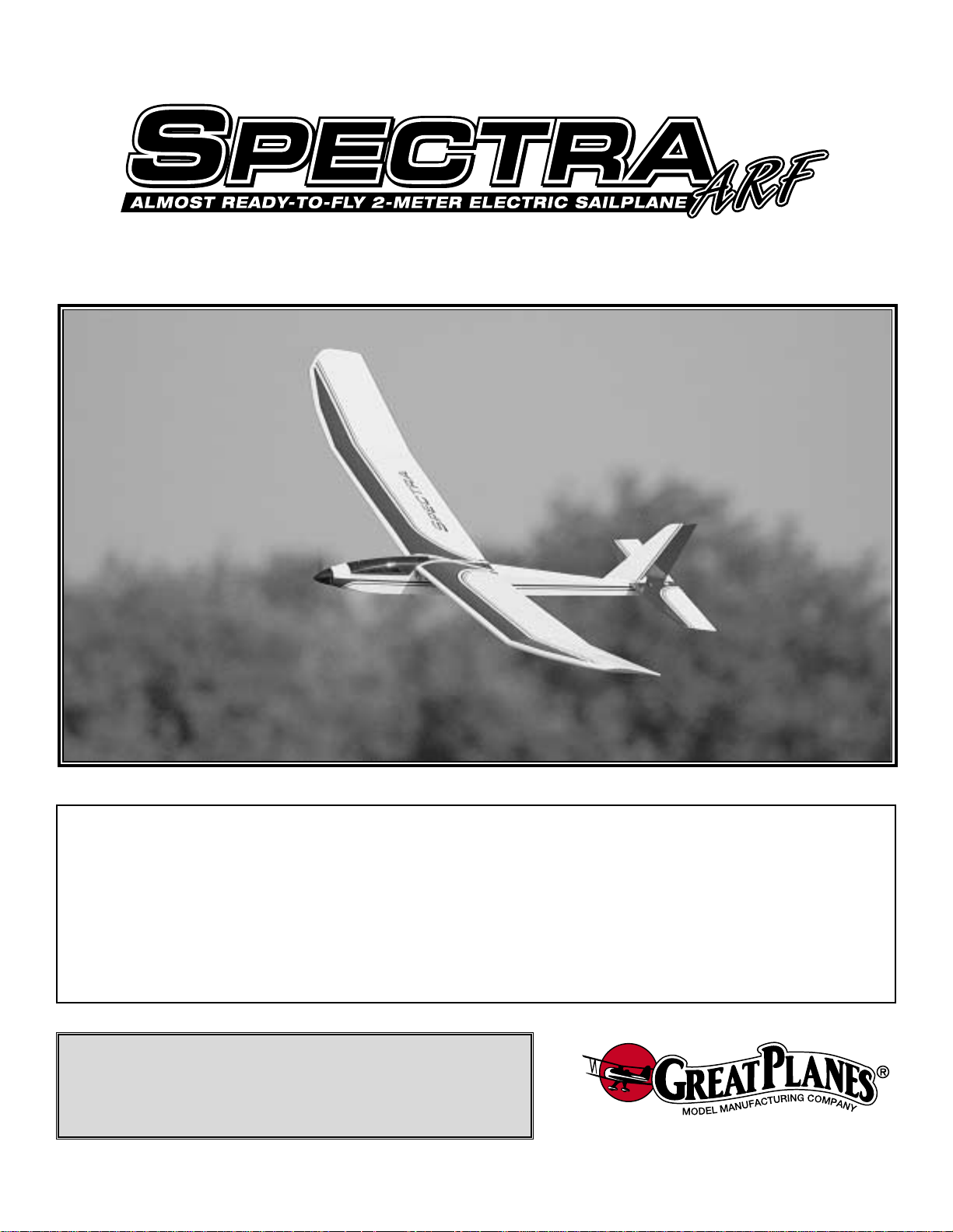
Your SPECTRA ARF is not a toy, but rather a sophisticated,
working model that functions very much like a full-size
sailplane. Because of its realistic performance, the SPECTRA
ARF, if not assembled and operated correctly, could
possibly cause injury to yourself or spectators and
damage property.
To make your R/C modeling experience totally enjoyable,
we recommend that you get experienced, knowledgeable
help with assembly and during your first flights.You’ll learn
faster and av oid risking your model before you’re truly ready to
solo.Your local hobby shop has information about flying clubs
in your area whose membership includes qualified instructors.
You can also contact the national Academy of Model
Aeronautics (AMA), which has more than 2,500 chartered
clubs across the country.Through any one of them, instructor
training programs and insured newcomer training are
available. Contact the AMA at the address or toll-free phone
number below.
Academy of Model Aeronautics
5151 East Memorial Drive
Muncie, IN 47302-9252
Tele. (800) 435-9262
Fax (765) 741-0057
or via the Internet at http://www.modelaircraft.org
1. Build the plane according to the instructions. Do not alter
or modify the model, as doing so may result in an unsafe or
unflyable model.
2.Take time to build straight, true and strong.
3. Use an R/C radio system that is in first-class condition,
and a correctly sized motor and components (batteries, etc.)
throughout your building process.
4.You must properly install all components so that the model
operates properly on the ground and in the air.
5.You must check the operation of the model before every
flight to ensure that all equipment is operating and that the
model has remained structurally sound. Be sure to check
nylon clevises or other connectors often and replace them if
they show signs of wear or fatigue.
Remember:Take your time and follow directions to end
up with a well-built model that is straight and true.
Please inspect all parts carefully before starting to
build! If any parts are missing, broken or defective,or if
you have any questions about building or flying this
airplane, please call us at:
(217) 398-8970
or e-mail us at:
productsupport@greatplanes.com.
If you are calling for replacement parts, please
reference the part numbers and the kit identification
number (stamped on the end of the carton) and have
them ready when calling.
Note:We, as the kit manufacturer, provide you with a top
quality kit and great instructions, but ultimately the quality
of your finished model depends on how you build it;
therefore, we cannot in any way guarantee the
performance of your completed model, and no
representations are expressed or implied as to the
performance or safety of your completed model.
PRO TECT YOUR MODEL,YOURSELF
& OTHERS...FOLLOW THESE
IMPORTANT SAFETY PRECAUTIONS
TABLE OF CONTENTS
2
Page 3
The SPECTRA ARF is a very stable and predictable
aircraft, allowing pilots of differing skill levels to enjoy it.It is
easy to build, flies great, and would be a great selection as
your first R/C airplane.
Items in parentheses (GPMQ4243) are suggested part
numbers recognized by most distributors and hobby shops
and are listed for your ordering convenience. GPM is the
Great Planes brand, TOP is the Top Flite®brand, HCA is the
Hobbico®brand.
❏
Minimum three-channel radio with two standard servos
❏ Electronic Speed Controller with BEC
❏ 6 or 7-cell rechargeable battery
These are the building supplies and tools that are required.
We recommend Great Planes Pro™CA and Epoxy glue.
❏ Pacer Formula 560 canopy glue (PAAR3300)
❏ Plastic wrap or wax paper
❏ Hobby knife and #11 blades (HCAR0105)
❏
1/2" [13mm] Latex foam rubber padding
(HCAQ1050)
❏ Phillips screwdriver
❏ Pliers
❏ Great Planes Pro Thin CA (1/2oz) (GPMR6001)
❏ Great Planes Pro Medium CA (1/2oz) (GPMR6007)
❏ Great Planes Pro Threadlocker (GPMR6060)
❏ Hand or electric drill with 1/16" [1.6mm], 3/32"
[2.3mm], 9/64" [3.6mm] and drill bits
❏ Top Flite Sealing Iron (TOPR2100)
❏ Top Flite Heat Gun (TOPR2000)
❏ Hobbico single-edge razor blades (HCAR0312)
❏ Hobbico Curved Tip Canopy Scissors for trimming
plastic parts (HCAR0667)
Remove the fuselage, wing panels, rudder assembly and
stabilizer assembly from their individual bags. Inspect all
items closely to check for any damage. If any damage is
found, contact the place where your SPECTRA ARF was
purchased, or Hobby Services, to obtain a replacement
for your damaged items. If any of the control surfaces are
attached, simply pull them apart and store the hinges in
a safe place until it is time to re-attach them.
Your SPECTRA ARF is covered using Top Flite
MonoKote®covering. Eliminate any wrinkles you find in the
covering by shrinking them away with a heat gun. Then,
apply pressure to the area with a covering iron and a
hot sock. This will securely bond the covering to the wood
so the wrinkles will be less likely to reappear in the future.
Several times during construction we refer to the “top” or
“bottom” of the model or a part of the model. It is
understood that the “top” or “bottom” of the model is as it
would be when the airplane is right side up and will be
referred to as the “top”even if the model is being worked on
upside-down.
Important Building Notes
General Inspection
Optional Supplies & Tools
Building Supplies & Tools
Required Accessories
PREPARATIONS
INTRODUCTION
3
Page 4
4
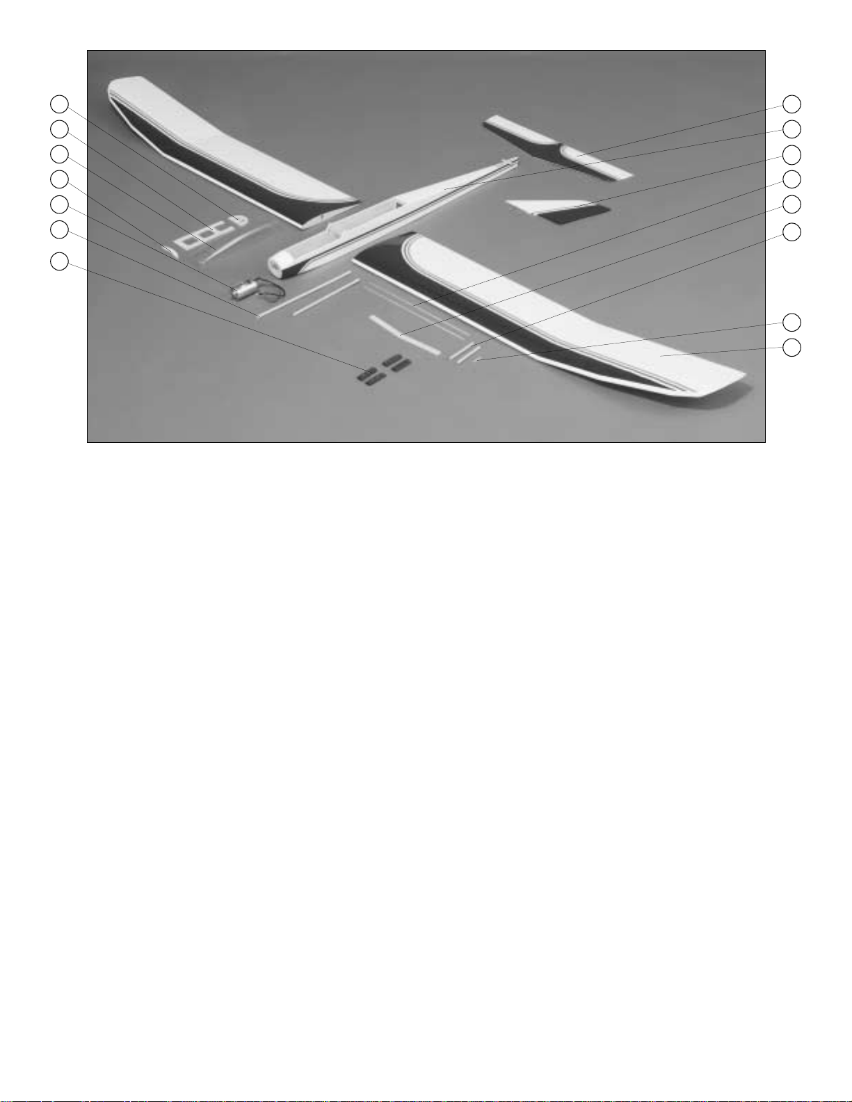
Key # Description Qty
1 REAR CANOPY BRACE...................1
2 CANOPY BRACE BRACE.................1
3 CANOPY............................................1
4 FRONT CANOPY BRACE.................1
5 MOTOR..............................................1
6 DOWEL PUSHRODS........................2
7 SHRINK TUBING...............................1
8 STAB & ELEVATOR ...........................1
Key # Description Qty
9 FUSELAGE........................................1
10 FIN & RUDDER.................................1
11 METAL PUSHRODS..........................2
12 WING JOINER...................................1
13 WING DOWELS ................................2
14 CANOPY DOWEL .............................1
15 WING (TWO HALVES) ......................1
8
9
10
11
12
13
14
15
1
2
3
4
5
6
7
PARTS LIST
REPLACEMENT PARTS
If needed, replacement parts for your Spectra ARF are available through your hobby supplier.
GPMA2340 ....Wing Kit
GPMA2341 ....Fuselage
GPMA2342 ....Tail Set
GPMA2343 ....Motor
GPMA2344 ....Battery
GPMA2345 ....ESC
GPMQ1690.....8 x 4 Folding Prop
Page 5
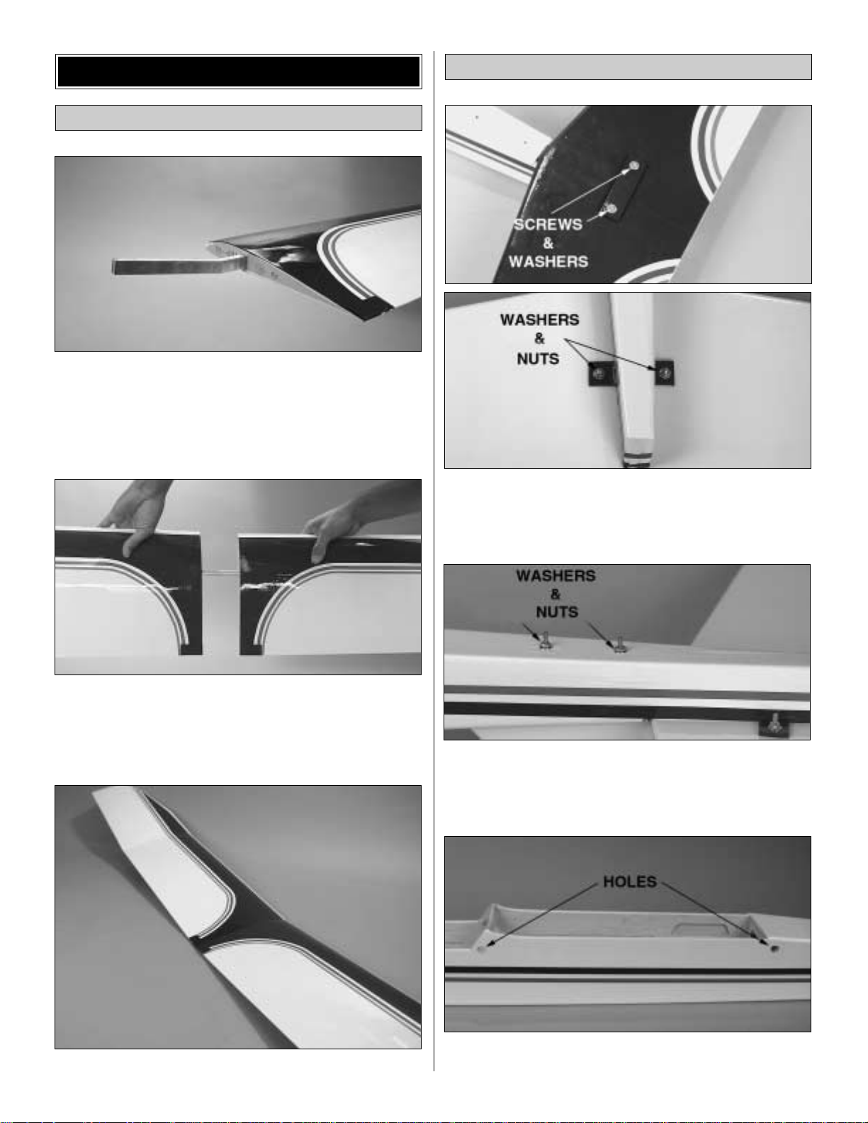
❏ 1. Locate the wing joiner and insert it into the r ight wing
joiner pocket as shown in the above picture.
❏2.Insert the other side of the wing joiner into the left wing
joiner pocket and slide the wings together.
❏ 3.Completed wing
❏ 1. Find and open the holes in the stabilizer covering for the
attachment screws.Attach the stabilizer to the fuselage using
two 2mm x 15mm screws, two 2mm nuts and four 2mm
washers.Use thread lock on the nuts to prevent loosening.
❏ 2. Open the holes on the top and bottom of the fuselage
covering for the fin attachment. Attach the fin using two
2mm washers and two 2mm nuts. Use Great Planes Pro
Threadlocker on the nuts to prevent loosening.
❏ 3. Install the wing dowels. Note that the smaller dowel
(7mm x 90mm) should be installed into the aft holes.
Tail Assembly
Wing Assembly
ASSEMBLY
5
Page 6

❏4.Join the rudder to the fin using the following procedure:
A. Drill a 3/32" [2.5mm] hole, 1/2" [13mm] deep, in the
center of the hinge slot. If you use a Dremel®MultiPro™for
this task, it will result in a cleaner hole than if you use a
slower speed drill. Drilling the hole will twist some of the
wood fibers into the slot, making it difficult to insert the
hinge, so you should reinsert the knife blade, working it
back and forth a few times to clean out the slot.
B. If the hinges don’t remain centered, remove the rudder
and insert a pin in the center of the hinges.
C.Attach the rudder to the fin using three hinges.Make sure
there is approximately a 1/64" [.04mm] gap between the
rudder and the fin.
D. Add six drops of thin CA to the center of the hinges on
both sides.Use a paper towel to absorb excess CA from the
hinge gap before it cures. Do not use CA accelerator;
allow the CA to cure slowly.
❏ 5. Use the same hinging method to join the elevator to
the stab.
❏ 6. Position one of the nylon control horns 1/2" [13mm]
up from the bottom of the rudder. Align the horn parallel to
the bottom of the rudder. Drill two 3/32" [2.5mm] holes
through the rudder using the horn as a guide. Harden the
holes using two or three drops of thin CA. Attach the nylon
control horn to the rudder using two 2mm x 15mm screws.
Tighten the screws into the horn back plate on the opposite
side of the rudder.
❏ 7. Position the remaining control horn in line with the
center of the fuselage on the bottom of the elevator. Attach
the control horn to the elevator using two 2mm x 15mm
screws.Tighten the screws into the horn back plate on the
opposite side of the elevator.
6
Page 7

❏ 1. Find the two hardwood sticks.The longer one is 1/4" x
3/8" x 2-1/8" [6.3mm x 9.5mm x 54mm] and it should be
inserted at the front of the radio tray slot. Insert the shor ter
stick (1/4" x 3/8" x 1-15/16" [ 6.3mm x 9.5mm x 49mm]) at
the
back of the slot.T est fit the servos you are going to use
between
the sticks and then glue the sticks in place with CA.
❏ 2. Install the servos using the hardware included with
your radio system. Note the location of the servo output
shafts in the photo.
❏ 3. Install the motor on the firewall using two supplied
3mm x 10 mm bolts and two 3mm washers.
❏4.Install the receiver,speed control and switch. Follow
your speed control manufacturer’s instr uctions closely. Use
thin foam to cushion the receiver .A Great Planes C-30
speed
control (GPMM2030) was used on the instruction model.
❏ 5. Make a hole on the side of the fuselage and route the
receiver antenna through the hole to the rear end of the
fuselage. Use fuel tubing through the hole to work as strain
relieve system.Also, use a cut piece of servo arm and guide
the antenna through at least two holes to act as a retainer.
Tie the end of the antenna to a small rubber band and use
a pin to hold the antenna in place at the rear fuselage.
❏ 6. Install the motor battery. Make sure there is enough
room in the front compartment to allow the motor battery to
slide out. The space is tight, so an option to remove the
battery is to remove the wing.
❏ 7. Find the two 12" (305mm) threaded one end pushrod
wires and make a cut 5" [127 mm] awa y from the end on the
unthreaded part of the rod. You should end up with two 5"
Radio & Motor Installation
7
Page 8

[127mm] long unthreaded wires and two 7" [178mm] long
threaded one end wires.
❏ 8. Make a 90° bend 1/4" [6mm] from the non-threaded
end in one of the threaded pushrod wires as shown in the
sketch. Make the same 90° bend in one end of the
remaining threaded and non-threaded pushrod wires.Wipe
off each wire using a paper towel dampened with rubbing
alcohol to remove any oil.
❏ 9. Cut the pushrod dowels from the hardwood dowels.
The elevator pushrod dowel should be 12" [305mm] long.
The rudder pushrod dowel should be 10" [255mm] long.
❏ 10. Drill a 5/64" [2mm] hole 1" [25mm] in from both ends
of each pushrod dowel.Cut a groove in each pushrod dowel
from the hole to the end of the dowel.
❏ 11. Inser t the 90° bend of one of the threaded pushrod
wires into one pushrod dowel.Insert the 90° bend of one of
the non threaded pieces of wire into the hole on the
opposite end of the pushrod dowel. Tack glue the wires in
place with a couple drops of CA. Repeat this procedure to
make the other pushrod.
❏ 12. Use the heat shr ink tubing at all the ends of each of
the pushrod dowels to hold everything in place as shown in
the photo. Use a heat gun to shrink the tubing. Apply a few
drops of thin CA to each end of the heat shrink tubing to
secure it.
❏ 13. Install the rudder pushrod. Thread a clevis 14-turns
onto the pushrod.Attach the clevis to the control horn at the
4th hole from the inside. Bend the pushrod as necessary to
allow for free movement. Use a silicone retainer to secure
the clevis.
❏ 14. Install the elevator pushrod. Center the elevator and
thread the clevis 14-turns onto the pushrod. Attach the
clevis to the control horn at the 4th hole from the inside.T rim
the opening at the rear of the fuselage as necessary to
allow the pushrod to move freely. Use a silicone retainer to
secure the clevis.
❏ 15. Center the rudder and the rudder ser vo arm. Attach
a FasLink onto the pushrod in the radio compartment and
8
Page 9

connect it to the servo arm at the last hole. Follo w the same
procedure for the elevator. Make sure all the FasLinks are
securely attached. Cut the excess pushrod 1/16" [1.6mm]
from the FasLink.
❏ 1. Place a piece of wax paper between the fuselage and
the bottom canopy base. Situate the front canopy brace
and rear canopy brace in place. Press all braces against
the fuselage to obtain their correct position. Glue the front
and the rear braces to the base with medium CA.The wax
paper will prevent the braces from accidentally being glued
to the fuselage. Note: You may have to sand the braces
slightly to get them to fit. For the instruction model we used
Great Planes Plan Protector™(GPMR6167).
❏ 2. Make a 9/64" [3.6mm] hole in the front canopy brace
and fuselage as shown. Insert the small hardwood dowel
into the hole until it extends all the way into the fuselage
hole. Glue in place with thick CA.Be careful not to glue the
dowel to the fuselage.
❏3.Test fit the canopy onto the canopy braces.Use Pacer
Formula 560 to glue the canopy to the canopy braces.
❏4.Trim the canop y flush with the base and the front of the
canopy braces but do not trim the back yet!
❏ 5. Temporar ily mount the wing in place on the fuselage.
Very carefully trim the back of the canopy, A LITTLE AT A
TIME, to fit over the wing. Curved tip scissors work well for
trimming the canopy.
❏ 6. Open the air intake on top of the canopy.
Canopy Installation
9
Page 10

❏1.Install the blades onto the folding propeller’s hub using
the steel pins supplied. Install the socket head set screw
provided in the folding propeller’s hub.This set screw will be
used to tighten the folding propeller to the motor’s shaft.
❏2.Install the spinner onto the folding propeller’s hub using
the bolts provided as shown above
❏ 3. Install the folding prop onto the motor’s shaft and
tighten the hub’s set screw.
❏ 1. The canopy is held in place with a rubber band. Loop a
medium size rubber band through the cut-out in the rear
canopy brace.Thread the rubber band through itself and then
hook it on the little extension on the fuselage former .T o remo ve
the canopy, pick up on the back until the dowel is clear of the
fuselage.To reinstall the canopy just do the opposite.
❏ 2.Trim the covering at the bottom of the airplane to open
the outlet holes.This will allow the cooling air for the motor
and motor battery to exit the fuselage.
Note: A piece of self-adhesive foam rubber weather
stripping
(not included) can be applied to the front of the fuselage
bottom to help protect it from getting nicked up during
landings.
Use the sketch to make sure the control surfaces are
moving the correct directions.
Radio Settings
Final Hookups & ChecksFolding Propeller Installation
10
Page 11

Note: This section is very important and must not be
omitted! A model that is not properly balanced will be
unstable and possibly unflyable.
The balance point (C.G.- Center of Gravity) is located directly
under the wing’s main spar 3-1/8" [79.5mm] from the LE.This
is the point at which your model should balance for your first
flights. Later, you may wish to shift the balance up to 3/8"
[9.5mm] forward or aft of the spar to change the flying
characteristics of your Spectra ARF. Moving the C.G. forward
of the spar will add some stability to the electric sailplane but
it will decrease its overall performance and increase its stall
speed.Moving the balance behind the spar makes the model
more agile with a lighter and “snapier” feel and improves the
Spectra ARF’s response to air currents. It also makes the
model less stable and can cause the model to “tuck under”or
dive when its flying speed increases. If you fly the Spectra
ARF with its C.G.behind the spar, pay close attention and do
not let it gain excessive speed.If it does “tuck under”and you
have plenty of altitude, give the airplane a little “down”
elevator and allow it to go under. When it starts to climb up
back of the outside loop its airspeed will drop and you can pull
out with some “up” elevator or roll out with full rudder. If you
do not have plenty of altitude, gently pull out with “up”elevator
but be careful and do not jerk it up or you may overstress the
wing structure.
With the wing attached to the fuselage, and all parts of the
model installed (ready to fly), lift the model by picking it up with
a finger on each bottom inner spar. If the tail drops when you
lift, the model is “tail heavy” and you must add weight to the
nose to balance. If the nose drops, it is “nose heavy” and you
must add weight to the tail to balance.The model should hang
with a slight nose down attitude.Add lead to the compartment
at the front of the fuselage to correct a tail heavy model.
DO NOT ATTEMPT TO FLY WITHOUT FIRST ACHIEVING
THE PROPER BALANCE.
This is a very important step and should be done
occasionally throughout the flying season. A sailplane’s
wing is most efficient when it is not twisted or warped at all.
“Washout” (wing trailing edges twisted up at the tip) helps
make a poor wing design fly better by adding some stability
(preventing stalls) at slow speeds but it cuts down on the
wing efficiency at normal speeds. The SPECTRA ARF’s
wing is designed to fly well at slow speeds without any
washout, and therefore we recommend you check to make
sure the wings are “flat” using the following procedure:
Set the wing so an inner panel is resting on a flat surface.
Any warp (twist) will show up by causing a corner of the
panel to rise off the work surface.
To remove the warp, gently twist the wing in the opposite
direction while a helper glides an iron or heat gun over the
covering on both the top and the bottom of the panel to reshrink the covering. Hold the twist until the covering cools
and then recheck for warps. It may take several tries to get
a warp out but it is worth it as you will end up with a
sailplane that flies straight and true and responds to air
currents like a high performance sailplane should.
Follow the same procedure to check all four wing panels
and then go back and double check them. Sometimes you
put a warp in one panel while trying to fix another. You
should also look at the tail surfaces as they too can warp.
Follow the battery charging procedures in your radio
instruction manual.You should charge your transmitter and
receiver batteries the night before you go flying, and at other
times as recommended by the radio manufacturer. Charge
your motor batteries as recommended by the manufacturer.
The best place to fly your R/C model is an AMA (Academy
of Model Aeronautics) chartered club field. Ask your hobby
shop dealer if there is such a club in your area and join.Club
fields are set up for R/C flying which makes your outing
safer and more enjoyable. The AMA can also tell you the
name of a club in your area. We recommend that you join
AMA and a local club so you can have a saf e place to fly and
Find a Safe Place to Fly
Charge the Batteries
PREFLIGHT
Checking for Warps
Balance the Model
The control throws are as follows:
UP DOWN
Elevator 1/2" [13mm] 1/2" [13mm]
LEFT RIGHT
Rudder 1-1/2" [38mm] 1-1/2" [38mm]
11
Page 12

also have insurance to cover you in case of a flying
accident. (The AMA address is listed on page 2 of this
instruction book).
If a club and its flying site are not available, you need to find
a large, grassy area at least 6 miles away from any other
R/C radio operation and away from houses, buildings and
streets. A schoolyard may look inviting but it is usually too
close to people, power lines and possible r adio interf erence .
If you are not thoroughly familiar with the operation of R/C
models, ask an experienced modeler to check to see that
you have the radio installed correctly and that all the control
surfaces do what they are supposed to.
Wherever you do fly, you need to check the operation of the
radio before every time you fly. This means with the
transmitter antenna collapsed and the receiver and
transmitter on, you should be able to walk at least 100 feet
away from the model and still have control. Have someone
help you. Have them stand by your model and, while you
work the controls, tell you what the various control surfaces
and your motor are doing.
Read and abide by the following Academy of Model
Aeronautics Official Safety Code excerpts:
1. I will not fly my model aircraft in competition or in the
presence of spectators until it has been proven to be airworthy
by having been previously successfully flight tested.
2. I will not fly my model aircraft higher than approximately
400 feet [120m] within 3 miles [2km] of an airport without
notifying the airpor t operator. I will give right of way to, and
avoid flying in the proximity of full-scale aircraft. Where
necessary an observer shall be utilized to supervise flying
to avoid having models fly in the proximity of full-scale
aircraft.
3.Where established, I will abide by the safety rules for the
flying site I use, and I will not willfully and deliberately fly my
models in a careless, reckless and/or dangerous manner.
1. I will have completed a successful radio equipment ground
check before the first flight of a new or repaired model.
2. I will not fly my model aircraft in the presence of
spectators until I become a qualified flyer, unless assisted
by an experienced helper.
3.I will perform my initial turn after takeoff away from the pit,
spectator and parking areas, and I will not thereafter
perform maneuvers, flights of any sort or landing
approaches over a pit, spectator or parking area.
First of all, if you are flying with other modelers check
to make sure they are not flying or testing on the same
frequency as your model.
Try to find an experienced pilot to help you with your first
flights. Although the SPECTRA ARF is very easy to fly, an
experienced pilot can save you a lot of time and possible
aggravation by helping you get your model in the air smoothly.
It is a good idea to do a couple of trim flights, without the
motor running, before each flying session to make sure the
plane is still in trim and the radio is working properly. The
model will survive a hard landing from 5 feet [1.5m] much
better than it will one from several hundred feet.The first few
trim flights should be done over a grass field.The longer the
grass the better (more cushion).
Turn on the transmitter first and then the receiver. Hold the
SPECTRA ARF under the wing with the nose pointed slightly
down and directly into the wind.Do not run the motor for these
test flights. It is very important that you launch the model with
the wings level and the nose pointing at a spot on the ground
about 50 feet [15m] in front of you.Have a friend stand off to the
side of you and tell you whether the nose is pointing up or
down. If the SPECTRA ARF is launched with the nose up or
launched too hard it will climb a few f eet, stall and fall nose first
straight down.With the nose pointed down slightly the sailplane
will accelerate down until it picks up enough flying speed then
level off and glide forward.The plane should be launched with
a gentle push forward.With a little practice you will be able to
launch it at just the right speed so it soars straight ahead in a
long and impressive glide path. Adjust the trims on your
transmitter to get the plane to fly straight ahead in a smooth
glide path.
Once you get the hang of launching it you can try turning the
plane during the trim flights by gently applying a “touch” of
right or left rudder.You can also try “flaring” the landings by
slowly applying a touch of up elev ator (pull the stick bac k) as
the plane nears the ground. The SPECTRA ARF will
continue to fly just a few inches off the ground for a
surprisingly long distance. It is important you don’t “overcontrol” the model. Make any control inputs slowly and
smoothly rather than moving the transmitter sticks abruptly.
Trim Flights
FLYING
Radio Control
General
AMA SAFETY CODE (
EXCERPTS
)
Range Check Your Radio
12
Page 13

Find a BIG, OPEN field for your first flights.The bigger the
better as you won’t have to worry about where you need to
land. Ground based objects (trees, poles, buildings, etc.)
seem to attract model airplanes like a magnet. Again, we
would like to recommend that you find an experienced
pilot to help you with these first flights.
Note: You need to remember that your radio control
responds as if you were sitting in the cockpit.When you
push the transmitter stick to the right,the rudder moves
to the plane’s right! This means that when the plane is
flying towards you it may seem like the rudder controls
are reversed (when you give “right” rudder the plane
turns to your left–which is the plane’s “right”). It is
sometimes easier to learn to fly the plane if you always f ace
your body in the direction the plane is flying and look over
your shoulder to watch the model.
Turn on your transmitter and then your receiv er and hold the
model as you did for the hand launched test flights. Hold it
firmly and move the throttle stick up to test the motor
operation.When satisfied that everything is responding as it
should, launch the model straight into the wind just as you
did without the motor running. It is important that you do not
throw the airplane up or it may stall and hit the ground.If you
launch it level or slightly down the airplane will accelerate
and start climbing on its own.
Don’t worry about accomplishing very much on your first
flights. Use these flights to get the “feel” of the controls and
the SPECTRA ARF’s flying characteristics.For the first few
seconds of the flight allow the airplane to gently climb
straight ahead. Try to keep the plane upwind and just
perform some gentle “S-turns”(always turning into the wind)
until it is time to set up for landing.Have a helper adjust the
trims on your transmitter (a little at a time) until it has
reached a comfortable soaring altitude (200' - 300' [60 -
90m]).
Turn the motor off and allow the SPECTRA ARF to soar
around, keeping the airplane upwind of yourself.When you
feel its getting too low, tur n the motor back on and climb
back to altitude. It can be very hard for a beginner to fly a
plane straight towards him as he would have to do if the
plane were downwind. While the SPECTRA ARF is gliding
have a helper to adjust the trims on your transmitter (a little
at a time) until the plane will fly straight and level with the
transmitter sticks in their neutral position.
When you can hear the motor starting to die off and/or the
plane does not want to climb anymore it is time to shut off
the motor for the last time (especially if you have BEC.) It is
important to remember that you no longer have enough
power to climb out again, so you only get one chance at
landing.When it is time to land, just continue performing the
gentle “S-turns” upwind and let the plane glide onto the
ground. Don’t worry about where the plane lands–just miss
any trees, etc. If you need to “stretch” a landing you can
switch the motor back on but do not expect it to be able to
carry you very far. When NiCd Batteries start going dead,
they really go dead in a hurry. An alternative to allowing the
battery to become weak before shutting the motor off for
good is to time the motor runs so you can leave enough
“juice” in the battery for a couple of “go arounds” if needed.
Practice flying directly into the wind (upwind of yourself)
without letting the plane get off course, and then turn and
come downwind until the plane is even with you and try it
again.When you are comfortable with flying directly into the
wind, start letting the plane go behind you (downwind) a
little before you start back upwind. Continue this until you
can fly directly towards you from downwind without getting
disoriented.At this point you can start to establish a “landing
pattern” and bring the sailplane in for a landing from
downwind. Always land into the wind. This enables the
plane to be flown as slowly (ground speed) as possible for
accurate and damage free landings.
It is probably not a good idea to try and fly around at a low
altitude with the motor on during your first flights. This will
cause the airplane’s speed to increase and make the
controls more responsive which is just what a beginner does
not need.
The SPECTRA ARF will climb to altitude several times on a
single charge allowing you to have flights well over ten
minutes without finding any “lift”.You should be able to get
two full climbs above 500' [150m] on a single charge
although there are many factors that figure into this.
Thermal soaring is one of the most intriguing of all aspects
of flying and the SPECTRA ARF was designed to excel at
thermal soaring even in the hands of a novice.It can be hard
for the av erage person to understand ho w a plane can fly f or
a long time and gain altitude without a motor!
Thermal Flying
Note: BEC is a system offered by most modern speed
controls that allow you to get rid of the radio battery and
use the motor battery as the means for supplying power
to the radio. The BEC will cut power to the motor when
the motor battery is low on charge but it will still give the
modeler enough power to use the radio normally for a
short time until landing. Keep in mind that while there is
still enough charge to use the radio when the motor
battery is low, so you should land within 10 to 15 minutes
of motor cut out time.
First Flights
13
Page 14

Thermals are a natural phenomenon that happen outside, by
the millions, every single day of the year. Thermals are
responsible for many things including forming several types of
clouds, creating breezes, and distributing plant seeds and
pollen.If you have e ver seen a dust de vil (which is nothing more
than a thermal that has picked up some dust), you have seen
a thermal in action.Their swirling action is very similar to that of
a tornado but of course much gentler. Most thermals have
updrafts rising in the 200 - 700 feet [60 - 220m] per minute
range but they have been known to produce updrafts of over
5,000 feet [1500m] per minute (that’s over 50 miles/hour
[30km/h] straight up!) These strong thermals can rip a plane
apart or carry the plane out of sight before the pilot can get out
of the updraft.
Thermals are formed by the uneven heating of the earth and
buildings, etc. by the sun. The darker colored surfaces
absorb heat faster than the lighter colors which reflect a
great deal of the sun’s energy bac k into space.These darker
areas (plowed fields, asphalt parking lots, tar roofs, etc.) get
warmer than the lighter areas (lakes, grassy fields, forests,
etc.). This causes the air above the darker areas to be
warmer than the air over the lighter areas and the more
buoyant warm air rises as the cooler, denser air forces its
way underneath the warmer air. As this warm air is forced
upward it contacts the cooler air of the higher altitudes and
this larger temperature difference makes the thermal rise
quicker.The thermal is gradually cooled by the surrounding
cooler air and its strength diminishes.Eventually the thermal
stops rising and any moisture contained in the once warm
air condenses and forms a puffy cumulus cloud. These
clouds, which mark the tops of thermals, are usually
between 2000 and 5000 feet [600 and 1500m] high.
It takes a lot of concentration to thermal soar effectively. An
electric sailplane can fly along the edge of a thermal and
unless the pilot is carefully watching the model he may not
realize the opportunity to gain some altitude. Because most
thermals are relatively small (a couple hundred feet in
diameter or less at 400' [120m] altitude) compared to the
rest of the sky, the sailplanes will rarely fly directly into the
thermal and start rising. Generally, the electric sailplane will
fly into the edge or near a thermal and the effects the
thermal has on the plane may be almost unnoticeable. As
the electric sailplane approaches a thermal, the wing tip that
reaches the rising air first will be lifted before the opposite
wing tip.This causes the plane to “bank” and turn away from
where we would like the plane to go.
When you are thermal soaring, try to fly as smoothly and
straight as possible. Trim the plane to fly in a straight line
and only touch the controls when you have to. Watch the
electric sailplane carefully and it will tell you what it is
encountering.When the electric sailplane flies directly into a
thermal it will either start r ising or stop sinking. Either case
is reason enough to start circling (especially in a contest
where every second counts). Fly straight ahead until you
feel like you are in the strongest lift, fly a couple of seconds
farther (so your circle will be centered in the strongest lift)
and then start circling in a fairly tight but smooth turn.When
the electric sailplane is low the turns have to be tighter to
stay in the strongest lift. As the plane gains altitude, the
turns can be larger and flatter.The flatter the turn, the more
efficient the plane is flying, but don’t be afraid to really
“crank” it into a steep bank when you are low. If you see the
plane falling off on one side of the turn, move your circle
over into the stronger lift. Thermals move along with the
wind so as you circle you will be swept along with it. Be
careful when thermaling, that you don’t get so far downwind
you can’t make it back to the field to land.
If the electric sailplane is flying along straight and all of a
sudden turns, let the plane continue to bank (you may have
to give it some rudder to keep it banking) until it has turned
270-degrees (3/4 of a full circle). Straighten out the bank
and fly into whatever turned the plane. If you encounter lift,
and you won’t every time, start circling just as you did when
flying directly into a thermal.
Thermals are generated all day long, but the strongest
thermals are produced when the sun is directly overhead.
10:00 am – 2:00 pm seems to be the best time to get those
“killer” thermals. Some of these thermals can be very large
and you may find it hard to get out of them. If you find
yourself getting too high, don’t dive the plane to get out of
the lift. Sailplanes are very efficient aircraft and they will
build up a lot of speed and could “blow up” in the rough air
of a thermal. The easiest way to lose altitude is to apply full
rudder and full up elevator.This will put the plane into a tight
spin that will not over stress the airframe but it will enable it
to lose altitude very quickly. This is especially helpful if the
sailplane gets sucked into a cloud or it gets too high to see.
The twirling action will give the sun a better chance of
flashing off of the wing and catching your attention. When
you are high enough and want to leave the thermal, add a
little down trim to pick up some speed and fly 90 degrees to
the direction of the wind.If you are not real high and want to
find another thermal, you may want to look upwind of the
last thermal.The same source that generated this thermal is
probably producing another. Just watch out for “sink” which
is often found behind and between thermals.
As you might expect, with all this air rising, there is also air
sinking.This air is the electric sailplane pilot’s nightmare that
can really make soaring challenging.“Sink” is usually not as
strong as the thermals in the same area, but it can be very
strong.Down drafts of many hundreds of feet per minute are
common on a good soaring day. These down drafts can
make a sailplane look like it is falling out of the air.Because
of this, it is important that you do not let the sailplane get too
far downwind.
Thermal Soaring
Facts About Thermals
14
Page 15

When encountering sink, immediately turn and fly 90
degrees to the direction of the wind (towards you if
possible). Apply a little “down elevator” and pick up some
speed to get out of the sink as fast as possible. Every
second you stay in the sink is precious altitude lost.
Pay Attention! – Pay close attention to the electric
sailplanes flying before you, watch them and try to establish
where and when the thermals are being formed. Thermals
are often formed in cycles and can be fairly regular , so if you
keep track of the time intervals you will have a pretty good
idea of when and where a thermal may be generated.
Watch The Birds! – Thermals suck up small insects that
many birds love to eat.A bunch of swallows flying around in
one area may indicate a thermal. Soaring birds (hawks,
vultures, eagles etc.) are the best thermal indicators. They
not only show you where the thermal is but they also show
you where the center is. These “Masters of the Sky” will
often fly right along with electric sailplanes.
Practice Those Landings! – Most thermal contests are
won or lost during the landing. Establish a particular landing
pattern and try to stick to it for all landings. Learn to shift
your pattern to account for the wind and the particular flying
field characteristics.
Concentrate! – Keep your eye on your electric sailplane
during your contest flights. Have a helper or your counter
watch the other planes in the air. Sometimes your electric
sailplane will wiggle so quickly or gently that you may miss
it if you are not paying close attention. If you find a
productive thermal, don’t leave it because your helper tells
you that someone else has found a different one.
Know Your Electric Sailplane! – Learn what your electric
sailplane will and won’t do and fly within this envelope.This
will allow you to ride thermals downwind while knowing
when you have to head back to make your landing safely.
Learn From The Wind! – Keep track of which way the wind
is blowing.If the wind suddenly shifts, there is some thermal
action fairly close to you. The air is probably being either
sucked up into a thermal or falling out of some sink.In either
case it is often a good idea to fly in the direction the wind is
blowing if your sailplane is in the general area.This will take
you towards a thermal if there is one or away from the sink,
both of which are desirable.
Have a ball! Remember to always stay in control and fly
in a safe manner.
Pointers for Contest Soaring
15
Page 16

BUILDING NOTES
Kit Purchased Date: _______________________
Where Purchased: _________________________
Date Construction Started: __________________
Date Construction Finished: _________________
Finished Weight: __________________________
Date of First Flight: ________________________
FLIGHT LOG
 Loading...