

Page 1
WARRANTY
Great Planes
®
Model Manufacturing Co. guarantees this kit to be free from defects in both material and workmanship at the date of
purchase.This warranty does not cover any component parts damaged by use or modification. In no case shall Great Planes’liability
exceed the original cost of the purchased kit. Further, Great Planes reserves the right to change or modify this warranty without notice.
In that Great Planes has no control over the final assembly or material used for final assembly, no liability shall be assumed nor
accepted for any damage resulting from the use by the user of the final user-assemb led product.By the act of using the user-assembled
product, the user accepts all resulting liability.
If the buyer is not prepared to accept the liability associated with the use of this product, the buyer is advised to return this
kit immediately in new and unused condition to the place of purchase.
To make a warranty claim send the defective part or item to Hobby Services at the address below:
Hobby Services
3002 N. Apollo Dr. Suite 1
Champaign IL 61822 USA
Include a letter stating your name, return shipping address, as much contact information as possible (daytime telephone number, fax
number, e-mail address), a detailed description of the problem and a photocopy of the purchase receipt. Upon receipt of the package
the problem will be evaluated as quickly as possible.
READ THROUGH THIS MANUAL BEFORE STARTING
CONSTRUCTION. IT CONTAINS IMPORTANT WARNINGS
AND INSTRUCTIONS CONCERNING THE ASSEMBLY
AND USE OF THIS MODEL.
GPMZ0204 for GPMA1049 V1.0© Copyright 2005
Champaign, Illinois
(217) 398-8970, Ext 5
airsupport@greatplanes.com
INSTRUCTION MANUAL
Wingspan: 100 in [2540mm]
Wing Area: 943 sq in [60.8 sq dm]
Weight: 4-4.5 lb [1800-2000g]
Wing Loading: 9.8-11 oz/sq ft [30-34 g/dm
2
]
Length: 54 in [1370 mm]
Radio: 5 Channel minimum, 7-9 channel with
sailplane mixing, 7 servos
™
Page 2

INTRODUCTION ...............................................................2
SAFETY PRECAUTIONS..................................................2
AMA...................................................................................3
DECISIONS YOU MUST MAKE........................................3
Radio Equipment .........................................................3
Spoilers .......................................................................3
ADDITIONAL ITEMS REQUIRED.....................................3
Adhesives & Building Supplies....................................3
Optional Items.............................................................4
IMPORTANT BUILDING NOTES......................................4
COMMON ABBREVIATIONS............................................4
KIT INSPECTION..............................................................5
KIT CONTENTS ................................................................5
ORDERING REPLACEMENT PARTS ..............................6
ASSEMBLE THE WING ....................................................7
Spoiler Option..............................................................7
Install the Aileron and Flap Servos.............................8
Finish the Wing..........................................................10
ASSEMBLE THE FUSE ..................................................11
Attach the Tail............................................................11
Install the Fuselage Servos .......................................12
Final Radio Installation..............................................14
Set the C.G................................................................14
Mount the Canopy and Tow Hook.............................15
Apply the Decals .......................................................16
GET THE MODEL READY TO FLY .................................16
Check the Control Directions ....................................16
Set the Control Throws..............................................16
Balance the Model Laterally ......................................17
PREFLIGHT.....................................................................17
Identify Your Model ....................................................17
Charge the Batteries .................................................17
Range Check.............................................................17
AMA SAFETY CODE (
EXCERPTS)....................................17
General......................................................................17
Radio Control ............................................................17
CHECK LIST ...................................................................18
THERMAL FLYING..........................................................18
Trimming Flights ........................................................18
Hi-Start Launch .........................................................18
First Flights ................................................................19
ADVANCED FEATURES.................................................19
FACTS ABOUT THERMALS...........................................19
THERMAL SOARING.......................................Back Cover
SLOPE SOARING.............................................Back Cover
BALLAST..........................................................Back Cover
Thank you for purchasing the Great Planes SPIRIT 100
ARF sailplane. Soaring offers a freedom that no other type
of flying can provide! With a little practice and some help
from mother nature, you will be able to defy gravity and
enjoy flights that can last for hours. The advanced wing
design incorporates flaps, spoilers and ailerons to provide
the ultimate in control when using computer radio mixing
functions.Take your time and follow directions to end up
with a well-built model that is straight and true.
For the latest technical updates or manual corrections to the
Great Planes Spirit 100 ARF, visit the Great Planes web site
at www.greatplanes.com. Open the “Airplanes” link, then
select the Spirit 100 ARF. If there is new technical
information or changes to this model, a “tech notice”box will
appear in the upper left corner of the page.
1. Your Spirit 100 ARF should not be considered a toy, but
rather a sophisticated, working model that functions very
much like a full-size airplane. Because of its performance
capabilities, the Spirit 100 ARF, if not assembled and
operated correctly, could possibly cause injury to yourself or
spectators and damage to property.
2. You must assemble the model according to the
instructions. Do not alter or modify the model, as doing so
may result in an unsafe or unflyable model. In a few cases
the instructions may differ slightly from the photos.In those
instances the written instructions should be considered
as correct.
3.You must take time to build straight, true and strong.
4.You must correctly install all R/C and other components so
that the model operates correctly on the ground and in the air .
5.You must check the operation of the model before every
flight to insure that all equipment is operating and that the
model has remained structurally sound. Be sure to check
clevises or other connectors often and replace them if they
show any signs of wear or fatigue.
6. If you are not an experienced pilot or have not flown this
type of model before, we recommend that you get the
assistance of an experienced pilot in your R/C club for your
first flights.If you’re not a member of a club, your local hobb y
shop has information about clubs in your area whose
membership includes experienced pilots.
PRO TECT YOUR MODEL,Y OURSELF
& OTHERS...FOLLOW THESE
IMPORTANT SAFETY PRECAUTIONS
INTRODUCTION
TABLE OF CONTENTS
2
Page 3
7. WARNING: The fuselage in this kit is made of fiberglass,
the fibers of which may cause ey e , skin and respiratory tract
irritation. Never blow into the fuse to remove fiberglass dust,
as the dust will blow back into y our e y es .Always w ear saf ety
goggles, a particle mask and rubber gloves when grinding,
drilling and sanding fiberglass parts. Vacuum the parts and
the work area thoroughly after working with fiberglass parts.
Remember:Take your time and f ollo w the instructions to
end up with a well-built model that is straight and true.
We urge you to join the AMA (Academy of Model
Aeronautics) and a local R/C club.The AMA is the governing
body of model aviation and membership is required to fly at
AMA clubs.Though joining the AMA provides many benefits,
one of the primary reasons to join is liability protection.
Coverage is not limited to flying at contests or on the club
field. It even applies to flying at public demonstrations and
air shows. Failure to comply with the Safety Code (excerpts
printed in the back of the manual) may endanger insurance
coverage.Additionally, training programs and instructors are
available at AMA club sites to help you get started the right
way. There are over 2,500 AMA chartered clubs across the
country. Contact the AMA at the address or toll-free phone
number below:
Academy of Model Aeronautics
5151 East Memorial Drive
Muncie, IN 47302-9252
Tele. (800) 435-9262
Fax (765) 741-0057
Or via the Internet at:
http://www.modelaircraft.org
IMPORTANT!!! T w o of the most important things you can do
to preserve the radio controlled aircraft hobby are to avoid
flying near full-scale aircraft and avoid flying near or over
groups of people.
This is a partial list of items required to finish the Spirit 100
ARF that may require planning or decision making before
starting to build.Order numbers are provided in parentheses.
❏ 5 channel radio with standard size receiver and battery
OR
❏ 7-9 channel radio with standard size receiver and battery
is recommended for maximum flight performance
❏ (2) Y-harnesses (FUTM4130) or (4) 9" extensions
(FUTM3910) utilizing a radio with flaperon mixing
❏ (4) Futaba
®
S3101 micro servos (FUTM0033) for ailerons
and flaps
❏ (2) Futaba S3004 standard size servos (FUTM0004)
The spoilers are highly recommended as they make it much
easier to land in smaller spaces or to lose altitude in a safe,
controlled manner.Y ou need an additional standard siz e servo
to operate the spoilers.
❏ (1) Futaba S3004 standard size servo (FUTM0004)
In addition to common household tools and hobby tools, this
is the “short list” of the most important items required to build
the Spirit 100 ARF.
Great Planes Pro™ CA and Epoxy glue
are recommended.
❏ 1/4" [6mm] R/C Foam Rubber (HCAQ1000)
❏ Velcro
®
Hook & Loop (GPMQ4480)
❏ 1/2 oz. [15g] Thin Pro CA (GPMR6001)
❏ Pro 30-Minute Epoxy (GPMR6047)
❏ Pro 6-Minute Epoxy (GPMR6045)
❏ Plan Protector (GPMR6167) or wax paper
❏ #1 Hobby Knife (HCAR0105)
❏ #11 Blades (5-pack, HCAR0211)
❏ 2 oz. [57g] Spray CA Activator (GPMR6035)
❏ Top Flite
®
MonoKote®Sealing Iron (TOPR2100)
❏ Mixing Cups (GPMR8056)
❏ Epoxy Brushes (6, GPMR8060)
❏ Silicone Glue (DEVR2500)
❏ Steel Shot
❏ Masking Tape (TOPR8018)
❏ Builder’s Triangle Set (HCAR0480)
❏ Drill bits: 1/16" [1.6mm], 5/64" [2mm]
Adhesives and Building Supplies
ADDITIONAL ITEMS REQUIRED
Spoilers
Radio Equipment
DECISIONS YOU MUST MAKE
AMA
We, as the kit manuf acturer, provide you with a top quality ,
thoroughly tested kit and instructions, but ultimately the
quality and flyability of your finished model depends on
how you build it; therefore, we cannot in any way
guarantee the performance of your completed model, and
no representations are expressed or implied as to the
performance or safety of your completed model.
3
Page 4
Here is a list of optional tools mentioned in the manual that
will help you build the Spirit 100 ARF.
❏ CA Debonder (GPMR6039)
❏ 36" Metal Ruler (HCAR0475)
❏ Hobbico
®
Duster™Can of Compressed Air (HCAR5500)
❏ Servo Horn Drill (HCAR0698)
❏ AccuThrow
™
Deflection Gauge (GPMR2405)
❏ CG Machine
™
(GPMR2400)
❏ Cover Sock (COVR2702)
• Whenever the term
glue
is written you should rely upon
your experience to decide what type of glue to use.When
a specific type of adhesive works best for that step, the
instructions will make a recommendation.
• Whenever just epoxy is specified you may use
either
30minute (or 45-minute) epoxy or6-minute epoxy. When 30minute epoxy is specified it is highly recommended that
you use only 30-minute (or 45-minute) epo xy, because you
will need the working time and/or the additional strength.
• Photos and sketches are placed before the step they
refer to .Frequently you can study photos in following steps
to get another view of the same parts.
• The Spirit 100 ARF is factory-covered with Top Flite
MonoKote film.Should repairs ever be required, MonoKote
can be patched with additional MonoKote purchased
separately. MonoKote is packaged in six-foot rolls, but
some hobby shops also sell it by the foot. If only a small
piece of MonoKote is needed for a minor patch, perhaps a
fellow modeler would give you some.MonoKote is applied
with a model airplane covering iron, but in an emergency a
regular iron could be used. A roll of MonoKote includes full
instructions for application. Following are the colors used
on this model and order numbers for six foot rolls.
True Red TOPQ0227
Cub Yellow TOPQ0220
Black TOPQ0208
Orange TOPQ0202
White TOPQ0204
Fuse = Fuselage
Stab = Horizontal Stabilizer
Fin = Ver tical Fin
LE = Leading Edge
TE = Trailing Edge
LG = Landing Gear
Ply = Plywood
" = Inches
mm = Millimeters
SHCS = Socket Head Cap Screw
COMMON ABBREVIATIONSIMPORTANT BUILDING NOTES
Optional Supplies and Tools
4
To convert inches to millimeters, multiply inches by 25.4
Inch Scale
0" 1" 2" 3" 4" 5" 6" 7"
0 10 20 30 40 50 60 70 80 90 100 110 120 130 140 150 160 170 180
Metric Scale
Page 5
5
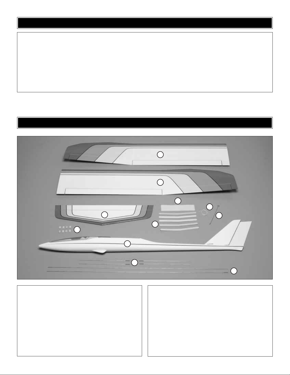
1 Left Wing
2 Right Wing
3 Horizontal Stabilizer
4 Hinge Strip
5 Wing Joiners (4–Wood, 1–Aluminum)
6 Spoiler String
7 Spoiler Activation Rod
8 Fuse and Canopy
9 12" Pushrods (4)
10 42" Pushrods (2)
11 Servo Blocks (8)
Kit Contents (Photographed)
Nylon Clevis (6)
Nylon Faslink Pushrod Keeper (6)
Nylon Small Control Horn (4)
Silicone Clevis Keeper (6)
6-32 x 3/4" Socket Head Cap Screw (5)
6-32 Nylon Lock Nut (1)
#6 Flat Washer (5)
2 x 3/8" Sheet Metal Screw (18)
2-56 x 1/2" Screw (6)
2-56 x 3/4" Socket Head Cap Screw (2)
Kit Contents (Not Photographed)
KIT CONTENTS
Before starting to build, take an inventory of this kit to make sure it is complete and inspect the parts to make sure they
are of acceptable quality. If any parts are missing or are not of acceptable quality , or if y ou need assistance with assemb ly,
contact Product Support. When repor ting defective or missing parts, use the part names exactly as they are written in
the Kit Contents list.
Great Planes Product Support:
3002 N Apollo Drive, Suite 1
Champaign, IL 61822
Telephone: (217) 398-8970, ext. 5
Fax: (217) 398-7721
E-mail:
airsupport@greatplanes.com
KIT INSPECTION
1
11
2
4
6
3
5
8
9
7
10
Page 6

6
ORDERING REPLACEMENT PARTS
Replacement parts for the Great Planes Spirit 100 ARF are available using the order numbers in the Replacement Parts
List that follows.The fastest, most economical service can be provided by your hobby dealer or mail-order company.
To locate a hobby dealer, visit the Great Planes web site at
www.greatplanes.com
.Choose “Where to Buy” from the menu
on the left side of the page.Follow the instructions provided on the page to locate a U.S., Canadian or International dealer.
If a hobby shop is not available, replacement parts may also be ordered from Tower Hobbies at
www.towerhobbies.com
,
or by calling toll free (800) 637-6050.
Parts may also be ordered directly from Hobby Services by calling (217) 398-0007, or via facsimile at (217) 398-7721, but
full retail prices and shipping and handling charges will apply. Illinois and Nevada residents will also be charged sales tax.
If ordering via fax, include a Visa®or MasterCard®number and expiration date for payment.
Mail parts orders and payments by personal check to:
Hobby Services
3002 N Apollo Drive, Suite 1
Champaign IL 61822
Be certain to specify the order number exactly as listed in the Replacement Parts List.Payment by credit card or personal
check only; no C.O.D.
If additional assistance is required, contact Product Support by e-mail at
productsupport@greatplanes.com
, or by telephone
at (217) 398-8970.
Replacement Parts List
Or
der Number Description How to Purchase
Missing pieces ................................................Contact Product Support
Instruction manual...........................................Contact Product Support
Full-size plans.................................................Not available
Kit parts listed below .......................................Hobby Supplier
GPMA1989............Fuselage Set
GPMA1987............Wing Set
GPMA1988............Tail Set
GPMA1989............Wing Joiner Set
GPMA1990............Canopy and Pilot
GPMA1991............Tow Hook Set
GPMA1992............Decal Set
Page 7

Spoilers are optional and can be made functional even
after you have flown the plane.
❏❏1. Use a sealing iron to securely attach the covering
to the spoiler and the wood surrounding it.
❏❏2. Trim the covering around the ends and TE of the
spoiler.DO NOT cut the along the LE
❏❏3. Trim covering from the spoiler string tube on the
bottom of the wing.
❏❏4.Insert the spoiler string in the string tube.Tie the end
to the spoiler control horn and secure with a drop of thin CA.
❏❏5. Cut a #64 rubber band in half. Clean the rubber
band with alcohol. Glue one end of the rubber band to the
front sheer web with a drop of medium CA.
❏❏6. Pull the rubber band up the spoiler and glue near
the TE with a drop of medium CA. NOTE: There should be
just enough tension to close the spoiler.
❏❏7. Cut the rubber band just behind the glue joint.
❏❏8.Pull the slack out of the spoiler string without opening
the spoiler and tie the spoiler hook to the string so that the
rear of the hook lines up with the front of the string opening.
Spoiler Option
ASSEMBLE THE WING
7
Page 8

❏❏9.Trim the excess string from the spoiler hook.
❏ 10. Repeat steps 1-9 for the second spoiler.
❏ 1.Cut a 3/16" x 1/2" [4 x 13mm] slot in the bottom of each
wing panel aligned with the hole in the root rib and 3/16"
[4mm] from the wing center.
❏ 2. Pull the servo leads up through the 3/16" x 1/2"
[4 x 13mm] slot.
❏ 3. Locate the openings for the flap and aileron servos in
the bottom of each wing panel. Trim out the covering and
seal the edges using a sealing iron.
❏ 4. Locate the four servo hatch covers and trim out the
servo arm openings. Seal the edges using a sealing iron.
❏ 5. Trial fit your servos on the covers and mark the
locations of the servo blocks. Using epoxy, glue the servo
blocks to the hatch cov ers.NOTE: The flap servos should be
oriented the same for both wing panels.
Install the Aileron and Flap Servos
8
Page 9

❏ 6.Attach the servos to the bloc ks using the hardware that
comes with your radio system. HINT: Dr ill a 1/16" [1.6mm]
pilot hole for the servo screws and strengthen the holes with
a drop of thin CA.
❏ 7. Attach the ser vo lead to the extension. Fit the servo
hatch to the wing. Use the holes in the cover as a guide and
drill four 1/16" [1.6mm] holes through the plywood servo
hatch mounts.
❏ 8. Temporarily mount the ser vo hatch cover to the wing
with four #2 x 3/8" [9.5mm] screws.Remove the screws and
hatch.Then, harden the holes in the wing with thin CA. Allow
the glue to dry and remount the servo hatch cover.
❏❏9. Align the aileron control hor n with the servo arm.
Glue the control horn to the aileron with a small drop of CA.
❏❏10. Drill two 1/16" [1.6mm] holes through the aileron.
Secure the control horns with two 2-56 x 1/2" [13mm]
screws and the nylon control horn back.
❏❏11.Screw a nylon clevis 15 turns onto each of the four
12" [305mm] pushrods. Slide a silicone retainer on each of
the nylon clevis.
9
Page 10

❏❏12. Attach the aileron clevis to the outer hole on the
control horn. With the ser vo and aileron centered mark the
location the pushrod crosses the servo arm. Bend a right
angle in the pushrod at the mark.
❏❏13. Cut the pushrod 1/4" [6mm] past the bend. Push
the pushrod through the servo arm. Retain the pushrod with
the nylon faslink.
❏❏14. Harden the control horn with thin CA and drill out
the second hole with a 1/16" drill.Attach the flap clevis to the
second hole on the control horn.
❏❏15. Plug the flap servo to the flap channel on your
radio. Make sure the servo arm is in the position shown in
the sketch. Align the flap with the wing TE and mark the
location the pushrod crosses the servo arm. Bend a right
angle in the pushrod at the mark.
❏❏16. Cut the pushrod 1/4" [6mm] past the bend. Push
the pushrod through the servo arm. Retain the pushrod with
the nylon faslink.
❏ 17. Repeat steps 7-14 for the other wing half.
❏ 1. Make a sandwich of the wing joiners as shown in the
sketch.Glue the wing joiners together with 6-minute epoxy and
clamp together. Use a paper towel dampened with alcohol to
remove the e xcess epoxy that has squeez ed out of the joiners.
Finish the Wing
10
SERVO
HORN
FASLINK
2-56 (.074")
PUSHROD WIRE
Plywood Joiners
Aluminum Joiner
Page 11

❏ 2. Remove the covering from the top and bottom of the
four wing bolt holes on the wing.
❏ 3. After the epoxy on the wing joiner has fully cured fit the
joiner in the wing.It might be necessary sand the joiner so it
will fit in the wing. The fit needs to be tight so sand small
amounts and take your time.
❏ 1. Trim the covering on the horizontal stabilizer from the
LE slot and the bolt hole.Apply thin CA to the exposed wood
in the LE slot.
❏ 2. Mount the stabilizer to the fuse with a 6-32 x 3/4"
[19mm] socket head cap screw and #6 washer.
❏ 3. Cut three 3/4" x 1" [19 x 25mm] CA hinges from the
supplied 2" x 9" [50 x 230mm] CA hinge strip. Snip off the
corners so they go into the rudder/fin easier.
Attach the Tail
ASSEMBLE THE FUSE
11
3/4" [19mm]
1" [25mm]
Page 12

❏ 4.Fit the rudder to the fin with the hinges.Glue both sides
of each hinge with 3 drops of thin CA.
❏ 5. Screw a nylon clevis 15 turns onto both of the 42"
[1067mm] pushrods. Slide a silicone retainer on each of the
nylon clevises.
❏ 6. If necessary , bend a slight angle in one of the pushrods
6" [150mm] from the end of the clevis.Slide this pushrod into
the rudder pushrod tube.
❏ 7. Align the r udder control horn with the rudder pushrod.
Glue the control horn to the rudder with a small drop of CA.
❏ 8. Drill two 1/16" [1.6mm] holes through the rudder.
Secure the control horn with two 2-56 x 3/4" [19mm] SHCS
and the nylon control horn back. Attach the clevis to the
outer hole on the control horn.
❏ 9. Slide the second 42" [1067mm] pushrod into the
elevator pushrod tube from the rear.
❏ 10. Mount the elevator control horn with two 2-56 x 5/8"
[15.9mm] screws. Attach the clevis to the second from the
outer hole.
❏ 1. Make two single sided servo arms that have the outer
hole 1/2" [13mm] from the servo mounting hole. Enlarge the
outer hole with a 5/64" drill bit.
Install the Fuselage Servos
12
5/64" [2mm]
1/2" [13mm]
Page 13

❏ 2. If you will be using the spoiler option make a servo arm
that has the outer hole at least 5/8" [16mm] from the servo
mounting hole. Enlarge the outer hole with a 5/64" dr ill bit.
❏ 3.Mount the rudder and elevator servos with the hardware
provided with the servos. If you will be using spoilers install
the spoiler servo also.NOTE:The spoiler servo mounts as far
right as it will go in the servo tray.
❏ 4.Plug the servos and batter y into your receiver.Turn on
the transmitter to center the servos. Attach the ser vo arms
to the servos as shown in the sketch.
❏ 5. Center the elevator and mark the pushrod where it
crosses the hole in the servo arm.
❏ 6.Bend the pushrod 90° up at the mark you made.
❏ 7. Attach the pushrod to the servo arm with a Faslink.
Trim the excess pushrod from flush with the Faslink.
❏ 8. Attach the rudder pushrod in the same manner you did
the elevator.
❏ 9. If you will be using spoilers slide the spoiler activation
rod forward through the hole in the former at the front of the
wing opening.
5/64" [2mm]
13
5/8" [16mm]
Spoiler
Rudder
FUTABA
S9001
Elevator
FUTABA
S9001
(Optional)
S9001
FUTABA
Page 14

❏ 10. Attach the Z-bend end of the spoiler activation rod to
the spoiler servo.
❏ 1. Attach the switch, charge jack, servos and servo
extensions to the receiver. Wrap the receiver in foam.
❏ 2. Push the receiver into the bottom of the fuse and retain
it with a small piece of Velcro®.
❏ 3.Drill a 1/16" [1.6mm] hole through the fuse side for the
antenna.Take a cut-off piece of servo arm with at least two
holes in it, and feed the antenna through two of the holes,
making a strain relief which protects the antenna from
accidentally being torn out of the receiver.P osition the strain
relief so that there is a small amount of slack between the
receiver and the when the strain relief is positioned against
the inside of the fuse.
❏ 4. Mount your switch in the canop y area with silicone glue ,
making sure it does not interfere with the pushrods or canopy.
❏ 1. Wrap the receiver battery in foam and tape. Tape the
battery to the outside of the fuse. NOTE: The batter y will be
installed after the CG is set.
Set the C.G.
Final Radio Installation
14
Page 15

❏ 2. Connect the wing servos and, if used, the spoiler hooks
to the loop end of the spoiler activation rod.The spoiler cables
will need to be pulled slightly to reach the loop on the wire.Be
careful no to over-extend the spoilers by pulling too hard on
the cable. Mount the wing with the four 6-32 x 3/4" [19mm]
SHCS and washers.
❏ 3. Tape the canopy to the opposite side of the fuse from
the battery.
❏ 4. Accurately mark the balance point on the bottom of the
wing on both sides of the fuselage. Use thin str ips of tape or
a felt-tip pen to make the marks.The balance point (CG) is
located 4-1/2" [115mm] back from the LE where the wing
meets the fuse. This is the balance point at which the model
should balance for your first flights.After initial trim flights you
may wish to experiment by shifting the balance up to 1/4"
[6mm] forward or back to change the flying characteristics.
❏ 5. Mix small amounts of the steel shot with epoxy and
pour it into the nose of the plane to set the CG.
❏ 6. After the epoxy has cured and the CG is confirmed
install the battery in the fuse.
❏ 1. Use needle nose pliers to open up the canopy hook so
there is a 1/16" [1.6mm] gap.
❏ 2. Drill a 3/64" [1.2mm] hole through the back of the
canopy. Screw the canopy hook into the canopy and secure
it with thin CA.
❏ 3. Attach a small rubber band to the fiberglass support at
the end of the hatch.
❏ 4. Loop the r ubber band over the canopy hook. Slide the
canopy in place.
Mount the Canopy and Tow Hook
15
4-1/2" [115mm]
Page 16

❏ 5. Mount the 6-32 tow hook to the fuse with the 6-32 nut
to lock it in place.
1.Use scissors or a sharp hobby knife to cut the decals from
the sheet.
2.Be certain the model is clean and free from oily fingerprints
and dust.Prepare a dishpan or small bucket with a mixture of
liquid dish soap and warm water–about one teaspoon of
soap per gallon of water.Submerse the decal in the soap and
water and peel off the paper backing. NOTE: Even though
the decals have a “stic ky-bac k”and are not the water transfer
type, submersing them in soap and water allows accurate
positioning and reduces air bubbles underneath.
3. Position decal on the model where desired. Holding the
decal down, use a paper towel to wipe most of the water a way.
4. Use a piece of soft balsa or something similar to squeegee
remaining water from under the decal. Apply the rest of the
decals the same way.
❏ 1. Tur n on the transmitter and receiver and center the
trims. If necessary, remove the servo arms from the servos
and reposition them so they are centered. Reinstall the
screws that hold on the servo arms.
❏ 2. With the transmitter and receiver still on, check all the
control surfaces to see if they are centered.If necessary, adjust
the clevises on the pushrods to center the control surfaces.
❏ 3. Make certain that the control surfaces respond in the
correct direction as shown in the diagram. If any of the
controls respond in the wrong direction, use the servo
reversing in the transmitter to reverse the servos connected
to those controls. Be certain the control surfaces have
remained centered. Adjust if necessary.
Use a Great Planes AccuThrow (or ruler) to accurately measure
and set the control throw of each control surface as indicated in
the chart that follows.If your radio does not have dual rates, we
recommend setting the throws at the high rate setting.
IMPORTANT: The Spirit 100 ARF has been extensively
flown and tested to arrive at the throws at which it flies
best. Flying your model at these throws will provide you
with the greatest chance for successful first flights.If, after
you have become accustomed to the way the Spirit 100
ARF flies, you would like to change the throws to suit your
taste, that is fine. However, too much control throw could
make the model difficult to control, so remember, “more is
not always better.”
These are the recommended control surface throws:
High Rate Low Rate
ELEVATOR: 5/8" [16mm] up 1/2" [13mm] up
5/8" [16mm] down 1/2" [13mm] down
RUDDER: 1-1/2" [38mm] right 1" [25mm] right
1-1/2" [38mm] left 1" [25mm] left
AILERONS: 3/4" [19mm] up 3/8" [9.5mm] up
3/4" [19mm] down 3/8" [9.5mm] down
Full Half
FLAPS: 2" [50mm] 1" [25mm]
SPOILERS: 2-1/4" [57mm] 1" [25mm]
Set the Control Throws
4-CHANNEL RADIO SETUP
Check the Control Directions
GET THE MODEL READY TO FLY
Apply the Decals
16
(STANDARD MODE 2)
4-CHANNEL
TRANSMITTER
ELEVATOR MOVES UP
4-CHANNEL
TRANSMITTER
RIGHT AILERON MOVES UP
LEFT AILERON MOVES DOWN
RUDDER MOVES RIGHT
FLAPS NEUTRAL
(STICK DOWN, FULL FLAPS)
4-CHANNEL
TRANSMITTER
4-CHANNEL
TRANSMITTER
Page 17

❏ 1. With the wing level, have an assistant help you lift the
model by the tip of the fuse and the bottom of the fin.Do this
several times.
❏ 2.If one wing always drops when you lift the model, it means
that side is heavy. Balance the airplane by adding weight to the
other wing tip. An airplane that has been laterally balanced
will track better in loops and other maneuvers.
No matter if you fly at an AMA sanctioned R/C club site or if you
fly somewhere on your own, you should always have your
name, address, telephone number and AMA number on or
inside your model.It is required at all AMA R/C club flying sites
and AMA sanctioned flying events. Fill out the identification tag
on the decal sheet and place it on or inside your model.
Follow the battery charging instructions that came with
your radio control system to charge the batteries. You
should always charge your tr ansmitter and receiver batteries
the night before you go flying, and at other times as
recommended by the radio manufacturer.
Ground check the operational range of your radio before the
first flight of the day. With the transmitter antenna collapsed
and the receiver and transmitter on, you should be ab le to walk
at least 100 feet away from the model and still have control.
Have an assistant stand by y our model and, while you work the
controls, tell you what the control surfaces are doing. If the
control surfaces do not respond correctly, do not fly! Find and
correct the problem first. Look for loose servo connections or
broken wires, corroded wires on old servo connectors, poor
solder joints in your battery pack or a defective cell, or a
damaged receiver crystal from a previous crash.
Read and abide by the following excerpts from the Academy
of Model Aeronautics Safety Code.For the complete Safety
Code refer to
Model Aviation
magazine, the AMA web site or
the Code that came with your AMA license.
1) I will not fly my model aircraft in sanctioned events , air shows,
or model flying demonstrations until it has been proven to be
airworthy by having been pre viously , successfully flight tested.
2) I will not fly my model aircraft higher than approximately
400 feet within 3 miles of an airport without notifying the
airpor t operator. I will give right-of-way and avoid flying in
the proximity of full-scale aircraft. Where necessary, an
observer shall be utilized to supervise flying to avoid
having models fly in the proximity of full-scale aircraft.
3) Where established, I will abide by the safety rules for the
flying site I use, and I will not willfully and deliberately fly my
models in a careless, reckless and/or dangerous manner.
5) I will not fly my model unless it is identified with my name
and address or AMA number, on or in the model. Note:
This does not apply to models while being flown indoors.
7) I will not operate models with pyrotechnics (any device
that explodes, burns, or propels a projectile of any kind).
1) I will have completed a successful radio equipment ground
check before the first flight of a new or repaired model.
2) I will not fly my model aircraft in the presence of
spectators until I become a qualified flier, unless assisted
by an experienced helper.
3) At all flying sites a straight or curved line(s) must be
established in front of which all flying takes place with the
other side for spectators. Only personnel involved with
flying the aircraft are allowed at or in the front of the flight
line. Intentional flying behind the flight line is prohibited.
4) I will operate my model using only radio control
frequencies currently allowed by the Federal
Communications Commission.
5) I will not knowingly operate my model within three
miles of any pre-existing flying site except in
accordance with the frequency sharing agreement
listed [in the complete AMA Safety Code].
Radio Control
General
AMA SAFETY CODE (
EXCERPTS
)
Range Check
CAUTION: Unless the instructions that came with your
radio system state differently, the initial charge on new
transmitter and receiver batteries should be done for 15
hours using the slow-charger that came with the radio
system.This will “condition” the batteries so that the next
charge may be done using the fast-charger of y our choice.
If the initial charge is done with a fast-charger, the
batteries may not reach their full capacity and you may be
flying with batteries that are only partially charged.
Charge the Batteries
Identify Y our Model
PREFLIGHT
Balance the Model Laterally
17
Page 18

❏ 1. Check the C.G. according to the measurements
provided in the manual.
❏ 2. Extend your receiver antenna and make sure it has a
strain relief inside the fuselage to keep tension off the
solder joint inside the receiver.
❏ 3.Balance your model
laterally
as explained in
the instructions.
❏ 4. Make sure all hinges are securely glued in place.
❏ 5. Confirm that all controls operate in the correct direction
and the throws are set up according to the manual.
❏ 6. Make sure any servo extension cords you may have
used do not interfere with other systems (servo arms,
pushrods, etc.).
❏ 7.Place your name, address, AMA number and
telephone number on or inside your model.
❏ 8. Cycle your receiver battery pack (if necessary) and
make sure it is fully charged.
❏ 9. If you wish to photograph your model, do so before
your first flight.
❏ 10. Range check your radio when you get to the flying field.
If you are not thoroughly familiar with the operation of R/C
models, ask an experienced modeler to check to see you
have the radio installed correctly and all the control surfaces
do what they are supposed to.
It is a good idea to do a couple of trim flights before each
flying session to make sure the plane is still in trim and the
radio is working properly.
Hold the Spirit 100 ARF under the wing with the nose
pointed slightly down and directly into the wind. Launch the
model with the wings level and the nose pointing at a spot
on the ground about 50 feet in front of you.If the sailplane is
launched with the nose up or launched too hard it will climb
a few feet, stall and fall nose first straight down. With the
nose pointed down slightly the sailplane will accelerate
down until it picks up enough flying speed, then level off and
glide forward.Adjust the trims on your transmitter to get the
plane to fly straight ahead in a smooth glide path.
A hi-start is the most common way to launch your Spirit 100
ARF. Follow the directions that came with the hi-start and lay
it out directly into the wind. Place the stake at the far upwind
edge of the flying field so the parachute will blow back onto
the flying field.
Hook the parachute up to the tow hook. Pull the plane back
approximately twice as far as the rubber is long or whatever
the hi-start instructions recommend.
Hold the plane above your head with the wings level and the
nose pointed slightly up and directly into the wind.Give the plane
a gentle push forward to get it flying and it will climb up like a kite .
You should not have to touch the elev ator during the launch.Use
the rudder stick to keep it going straight up. You will find the
ailerons are not very responsive during the first part of the
launch. As the rubber relaxes the plane will fly off the hi-start.
The wing and airframe of ANY sailplane—even those ha ving
composite structures—can be destroyed by excessive
stress if a winch is not used properly.Sailplanes with a builtup balsa/ply wing and thin airfoil are especially vulnerable.
Proper winch operation is the responsibility of its user.Without
appropriate restraint, wing failure can result.Therefore:
• Do NOT attempt full pedal launches with the Spirit
100 ARF.
• Understand that you minimize the risk of wing failure
by launching with a Hi-Start.
• If you must launch with a winch, please use the winch
pedal responsibly!
Great Planes subjects all new airplane kit and ARF models
to rigorous stress-testing.Tests showed no weakness in the
Spirit 100 ARF wing during hi-start or winch launching.
Winch launches were conducted in a reasonable manner,
knowing that overzealous use could fold the wings.
Hi-Start Launch
Trimming Flights
FLYING
During the last few moments of preparation your mind may
be elsewhere anticipating the excitement of the first flight.
Because of this, you may be more likely to overlook certain
checks and procedures that should be performed before the
model is flown.To help avoid this, a check list is provided to
make sure these important areas are not overlooked. Many
are covered in the instruction manual, so where appropriate,
refer to the manual for complete instructions. Be sure to
check the items off as they are completed.
CHECK LIST
18
Page 19

Use these flights to get the “feel”of the controls and the Spirit
100 ARF’s flying characteristics. Adjust the trims on your
transmitter (a little at a time) until the plane will fly straight and
level with the transmitter sticks in their neutral positions.
The Spirit 100 ARF is a very gentle plane that flies well in
light to moderate winds. Practice coordinating ailerons and
rudder until you can get a tight turn that is relatively flat.
Bank the sailplane with rudder and ailerons first, then add
elevator to pull it around.When setting up to land, point the
nose into the wind just downwind of where you want to land.
Line up with your landing spot and slowly feed in flaps (or
Crow). Add more or less flaps to control your descent angle
and speed so you end up hitting the spot.
There are several types of mixing the Spirit 100 ARF can
take advantage of if you have a “computer radio”.
Launch Camber: Lowering the flaps and ailerons during the
launch will produce a steeper climb, giving you better altitude.
A good place to start is about 15 degrees of flap and 5 degrees
of aileron drop (the flaps will drop about three times more than
the ailerons).This automatically puts some washout in the wing
which adds stability for arrow straight launches. If you don’t
have a switch for launch camber, just use the flaps for launch.
Crow:This is used to lose altitude quickly and to control your
glide for spot landings. This mixing is tied to the flap stick
(throttle)and allows the ailerons to come up as the flaps drop.
Be sure to use plenty of aileron differential when using
CROW mixing because the ailerons become less effective at
very high angles of deflection. Also use maximum rudder
coupling at full CROW. If you don’t have CROW capabilities
just use flaps and make sure you hav e full rudder throw when
the flaps start coming down. It is a good idea to get lined up
on the spot before dropping the flaps very much because
the rudder will become sluggish with the flaps down at slow
speeds. Note: You will need to mix in a little down elevator
with the flaps to keep the plane tracking straight.
Aileron/Rudder Coupling: This is used to allow the
sailplane to make efficient, non-slipping, non-skidding turns.
You will need to experiment to find the proper amount of
throw required to do this but 1"[25mm] of rudder throw at full
aileron is probably a good place to start.
Elevator/Camber Coupling - This is a neat type of mixing
that allows the TE (ailerons and flaps) to respond to the
elevator. When properly set up, this can be very useful when
floating around in light air or when trying to thermal very
tightly. This mixing can change the flying characteristics of
the plane so start off small and get used it. A good place to
start would be 1/8" [3mm] of TE drop at full up elevator.
Controlling the Wing Trailing Edge (Camber): The wing
camber is usually controlled by a 3-position switch. The
traditional way of setting this switch is to have: the middle
position set to neutral camber, one direction for reflex (the
entire TE raises about 1/16" [1.5mm]) and the other direction
for positive camber (the entire TE drops about 3/32" [2.5mm]).
This way of programming the s witch is g reat f or good thermaldays or days with a lot of wind where you might need the
reflex capability for zooming up wind. The other way we set
this switch is to have the “back” position for neutral camber,
the middle position for a slight amount of positive camber
[1/32" [1mm] - 1/16" [2mm]) and the forward position f or more
positive camber [3/32" [2.5mm] - 1/8" [3mm]). The middle
position can be used once good air is located or when trying
to gain a few extra seconds of air time. Nor mally the L/D will
not be as great as neutral camber but the sailplane will float
better.The forward position is when the sailplane is low and
encounters lift, don’t panic, just hit the switch. The SPIRIT
ELITE will really slow up and will thermal “on a dime”.This setup is great for duration type flying without a lot of wind.
Thermals are a natural phenomenon that happen outside,
by the millions, every single day of the year. Thermals are
responsible for many things including forming several types
of clouds, creating breezes and distributing plant seeds and
pollen. If you have ever seen a dust devil (which is nothing
more than a thermal that has picked up dust), you hav e seen
a thermal in action.Their swirling action is very similar to that
of a tornado but much gentler.Most thermals have updrafts
rising 200-700 feet per minute but have been known to
produce updrafts of over 5,000 f eet per min ute These strong
thermals can rip a plane apart or carry the plane out of sight
before the pilot can get out of the updraft.
Thermals are formed by the uneven heating of the earth and
buildings, etc.by the sun.The darker colored surfaces absorb
heat faster than the lighter colors which reflect a great deal of
the sun’s energy bac k into space .These darker areas (plowed
fields, asphalt parking lots, tar roofs, etc.) get warmer than the
lighter areas (lakes, grassy fields, forests, etc.). This causes
FACTS ABOUT THERMALS
ADVANCED FEATURES
First Flights
19
Page 20

the air above the darker areas to be warmer than the air over
the lighter areas and the more buoyant warm air rises as the
cooler, denser air f orces its wa y underneath the warmer air .As
this warm air is forced upward it contacts the cooler air of the
higher altitudes and this larger temperature difference makes
the thermal rise quicker.The thermal is gradually cooled by the
surrounding cooler air and its strength diminishes. Eventually
the thermal stops rising and any moisture contained in the
once warm air condenses and forms a puffy cumulus cloud.
These clouds, which mark the tops of thermals, are usually
between 2000 and 5000 feet high.
As the glider approaches a thermal, the wing tip that reaches
the rising air first will be lifted before the opposite wing tip.This
causes the plane to “bank”and turn away from where we would
like the plane to go.The best way to get back in is to continue
the bank and turn 270 degrees straight into the thermal.
When you are thermal soaring, try to fly as smoothly and
straight as possible.Trim the plane to fly in a straight line and
only touch the controls when you have to. Watch the
sailplane carefully and it will tell you what it is encountering.
When the sailplane flies directly into a thermal it will either start
rising or stop sinking. Either case is reason enough to start
circling.Fly straight until you feel lik e you are in the strongest lift,
then fly a couple of seconds farther so your circle will be
centered in the strongest lift.Thermals travel with the wind, so
be careful that you don’t get too far downwind that y ou can’t get
back.If you find yourself getting too high, don’t div e the plane to
get out of the lift. Sailplanes are very efficient aircraft and they
will build up a lot of speed and could “blow up” in the rough air
of a thermal. The easiest way to lose altitude is to apply full
rudder and full up elevator. This will put the plane into a tight
spin that will not over stress the airframe but it will enable it to
lose altitude very quickly. This is especially helpful if the
sailplane gets sucked into a cloud or it gets too high to see.
As you might expect, with all this air rising, there is also air
sinking. This air is the sailplane pilot’s nightmare that can
really make soaring challenging. “Sink” is usually not as
strong as the thermals in the same area but sometimes can
be. Because of this, it is important you do not let the
sailplane get too far downwind.
Watch the birds! - Thermals suck up small insects many
birds love to eat. A bunch of swallows flying around in one
area may indicate a thermal.Soaring birds (hawks, vultures,
eagles etc.) are the best thermal indicators. They not only
show you where the thermal is but they also show you
where the center is.These “Masters of the sky” will often fly
right along with sailplanes.
Practice those landings! Most thermal contests are won or
lost during the landing. Establish a particular landing patter n
and try to stick to it for all landings.Lear n to shift your pattern
to account for the wind and particular flying field
characteristics. Flaps can be very useful during contest
landings.They allow you to bring the sailplane in for a landing
higher or faster than normal to guard against any last minute
sink or gusts and dump the extra altitude and speed at the last
second.They can also be used to help control your skid.Flaps
will stop the plane from sliding a little quicker. You can also
“steer” the plane while it is sliding along the ground. Don’t
expect to be able to “horse it around”but you can gain v aluable
inches by using the rudder to guide it towards the spot as it
slides to a stop.Be very careful not to “ground loop” the plane
since you will lose your landing points if the plane flips over.
To be able to slope soar, you need a slope with a smooth
piece of land (or water) out in front of it and a breeze blowing
pretty close to straight up the slope.The higher and steeper
the hill or cliff the better. Also the larger and smoother the
land out in front the better.The air flowing towards the hill, is
forced up and can generate a very large area of lift. Behind
the hill is a large area of turbulent air that can be very
dangerous to try to fly in. The faster the wind is blowing the
stronger the lift and turbulence will be.
To fly off a slope, stand near the edge and throw the sailplane
(nose down) into the wind. As the sailplane flies out into the
“band” of lift it will begin to gain altitude.Turn and fly parallel to
the slope and make all of your turns into the wind (especially
when you are close to the slope).You will be surpr ised at the
altitude you can gain just from slope lift.Thermals will often be
“popped loose” by these slopes. If you catch a thermal and
follow it downwind, be v ery careful to stay high enough to mak e
it back to the slope without flying through the turbulent air.
Landings can be very tricky on some slopes. On gentle slopes
you can often fly very close to the top of the slope and “slide”
into the top of the slope without encountering any turbulent air.
On steeper slopes you may ha ve to be a little more aggressive
to get the plane out of the lift. In any case it is a good idea to
plan your landing before you launch your plane.
In strong wind conditions, you may want to add ballast
(weight) to the sailplane to increase its wing loading which
increases its normal flying speed. Increasing the weight of
your sailplane does not change its “glide ratio” but it does
make it fly faster which makes it sink a proportional amount
faster. Because of this faster sink rate, you need to be very
cautious when ballasting for a thermal contest. In duration
type contests only use ballast on very windy days that also
have a lot of thermal activity. Center the weight directly on
the center of gravity of the plane so you can add ballast
without having to re-balance the plane. When learning to
ballast your plane, start out small and work your way up.
HAVE FUN AND GOOD LIFT!!
BALLAST
SLOPE SOARING
THERMAL SOARING
 Loading...