

Page 1
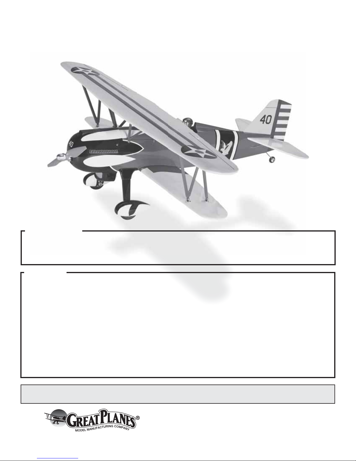
CURTISS P-6E HAWK
INSTRUCTION MANUAL
SPECIFICATIONS
Wingspan:
Length:
Weight:
43.5 in [1105mm]
34 in [865mm]
3.75– 4.5 lb [1700–2040 g]
Wing Area:
Wing Loading:
WARRANTY
Great Planes® Model Manufacturing Co. guarantees this kit to
be free from defects in both material and workmanship at the
date of purchase. This warranty does not cover any component
parts damaged by use or modification. In no case shall Great
Planes’ liability exceed the original cost of the purchased kit.
Further, Great Planes reserves the right to change or modify this
warranty without notice.
In that Great Planes has no control over the final assembly or
material used for final assembly, no liability shall be assumed nor
accepted for any damage resulting from the use by the user of
the final user-assembled product. By the act of using the
user-assembled product, the user accepts all resulting liability.
If the buyer is not prepared to accept the liability associated
with the use of this product, the buyer is advised to return
READ THROUGH THIS MANUAL BEFORE STARTING CONSTRUCTION. IT CONTAINS IMPORTANT
INSTRUCTIONS AND WARNINGS CONCERNING THE ASSEMBLY AND USE OF THIS MODEL.
2
352 in
25– 29 oz/ft
[76–88 g/dm2]
this kit immediately in new and unused condition to the
place of purchase.
To make a warranty claim send the defective part or item to
Hobby Services at the address below:
Include a letter stating your name, return shipping address, as
much contact information as possible (daytime telephone
number, fax number, e-mail address), a detailed description of
the problem and a photocopy of the purchase receipt. Upon
receipt of the package the problem will be evaluated as quickly
as possible.
[22.7 dm2]
2
3002 N. Apollo Dr. Suite 1
Champaign IL 61822 USA
Radio: 4 channel radio (minimum)
Electric
Power:
Hobby Services
RimFire™ .32, (42-50-800)
Outrunner Brushless
Entire Contents © 2014 Hobbico,® Inc. All rights reserved.
Champaign, Illinois
(217) 398-8970, Ext 5
airsupport@greatplanes.com
GPMA1164
Page 2
TABLE OF CONTENTS
INTRODUCTION . . . . . . . . . . . . . . . . . . . . . . . . . . . . . . . . 2
Academy of Model Aeronautics . . . . . . . . . . . . . . . . . . 2
SAFETY PRECAUTIONS . . . . . . . . . . . . . . . . . . . . . . . . . 2
DECISIONS YOU MUST MAKE. . . . . . . . . . . . . . . . . . . . . 3
Radio Equipment . . . . . . . . . . . . . . . . . . . . . . . . . . . . . 3
Transmitter . . . . . . . . . . . . . . . . . . . . . . . . . . . . . . . . . . 3
Receiver. . . . . . . . . . . . . . . . . . . . . . . . . . . . . . . . . . . . 3
Servos . . . . . . . . . . . . . . . . . . . . . . . . . . . . . . . . . . . . . 3
Connectors. . . . . . . . . . . . . . . . . . . . . . . . . . . . . . . . . . 3
Motor Recommendations. . . . . . . . . . . . . . . . . . . . . . . 3
Electronic Speed Control . . . . . . . . . . . . . . . . . . . . . . . 3
Propeller. . . . . . . . . . . . . . . . . . . . . . . . . . . . . . . . . . . . 3
Flight Battery . . . . . . . . . . . . . . . . . . . . . . . . . . . . . . . . 3
ADDITIONAL ITEMS REQUIRED . . . . . . . . . . . . . . . . . . . 3
Required Adhesives & Building Supplies. . . . . . . . . . . 3
Optional Supplies and Tools. . . . . . . . . . . . . . . . . . . . . 4
IMPORTANT BUILDING NOTES. . . . . . . . . . . . . . . . . . . . 4
KIT INSPECTION. . . . . . . . . . . . . . . . . . . . . . . . . . . . . . . . 4
ORDERING REPLACEMENT PARTS . . . . . . . . . . . . . . . . 4
KIT CONTENTS. . . . . . . . . . . . . . . . . . . . . . . . . . . . . . . . . 5
PREPARATIONS . . . . . . . . . . . . . . . . . . . . . . . . . . . . . . . . 5
ASSEMBLE THE WINGS. . . . . . . . . . . . . . . . . . . . . . . . . . 5
Install the Aileron Servos & Pushrods . . . . . . . . . . . . . 5
ASSEMBLE THE FUSELAGE . . . . . . . . . . . . . . . . . . . . . . 8
Install the Main Landing Gear . . . . . . . . . . . . . . . . . . . 8
Install the Wings, Cabanes & Struts. . . . . . . . . . . . . . . 9
Install the Tail Assembly. . . . . . . . . . . . . . . . . . . . . . . 11
Install the Elevator, Rudder Servos and Receiver . . . 13
Install the Motor, ESC and Cowl . . . . . . . . . . . . . . . . 14
Install the Wheels and Wheel Pants. . . . . . . . . . . . . . 16
Final Details . . . . . . . . . . . . . . . . . . . . . . . . . . . . . . . . 17
Apply the Decals . . . . . . . . . . . . . . . . . . . . . . . . . . . . 17
GET THE MODEL READY TO FLY . . . . . . . . . . . . . . . . . 18
Check the Control Directions . . . . . . . . . . . . . . . . . . . 18
Set the Control Throws. . . . . . . . . . . . . . . . . . . . . . . . 19
Finish the Model. . . . . . . . . . . . . . . . . . . . . . . . . . . . . 19
Balance the Model (C.G.). . . . . . . . . . . . . . . . . . . . . . 19
Balance the Model Laterally. . . . . . . . . . . . . . . . . . . . 20
PREFLIGHT . . . . . . . . . . . . . . . . . . . . . . . . . . . . . . . . . . . 20
Identify Your Model. . . . . . . . . . . . . . . . . . . . . . . . . . . 20
Charge the Batteries . . . . . . . . . . . . . . . . . . . . . . . . . 20
Range Check . . . . . . . . . . . . . . . . . . . . . . . . . . . . . . . 20
MOTOR SAFETY PRECAUTIONS . . . . . . . . . . . . . . . . . 20
AMA SAFETY CODE EXCERPTS . . . . . . . . . . . . . . . . . 21
General . . . . . . . . . . . . . . . . . . . . . . . . . . . . . . . . . . . 21
Radio Control . . . . . . . . . . . . . . . . . . . . . . . . . . . . . . . 21
CHECK LIST . . . . . . . . . . . . . . . . . . . . . . . . . . . . . . . . . . 21
FLYING. . . . . . . . . . . . . . . . . . . . . . . . . . . . . . . . . . . . . . . 22
Takeoff . . . . . . . . . . . . . . . . . . . . . . . . . . . . . . . . . . . . 22
Flight . . . . . . . . . . . . . . . . . . . . . . . . . . . . . . . . . . . . . 22
Landing . . . . . . . . . . . . . . . . . . . . . . . . . . . . . . . . . . . 22
INTRODUCTION
The Curtiss P-6E Hawk is an iconic airplane loved by aviation
enthusiasts everywhere. The attention to detail in this airplane,
coupled with its great looks in the air and on the ground, will
impress you and those who watch it fl y!
For the latest technical updates or manual corrections to the
“Curtiss P-6E Hawk” visit the Great Planes web site at www.
greatplanes.com. Open the “Airplanes” link, and then select the
“Curtiss P-6E Hawk EP.” If there is new technical information
or changes to this model a “tech notice” box will appear in the
upper left corner of the page.
Academy of Model Aeronautics
We urge you to join the AMA (Academy of Model Aeronautics)
and a local R/C club. The AMA is the governing body of model
aviation and membership is required to fl y at AMA clubs.
Though joining the AMA provides many benefi ts, one of the
primary reasons to join is liability protection. Coverage is not
limited to fl ying at contests or on the club fi eld. It even applies
to fl ying at public demonstrations and air shows. Failure to
comply with the Safety Code (excerpts printed in the back of
the manual) may endanger insurance coverage. Additionally,
training programs and instructors are available at AMA club
sites to help you get started the right way. There are over 2,500
AMA chartered clubs across the country. Contact the AMA at
the address or toll-free phone number below:
Academy of Model Aeronautics
5151 East Memorial Drive
Muncie, IN 47302-9252
Tele. (800) 435-9262
Fax (765) 741-0057
Or via the Internet at: http://www.modelaircraft.org
IMPORTANT!!! Two of the most important things you can
do to preserve the radio controlled aircraft hobby are to avoid
fl ying near full-scale aircraft and avoid fl ying near or over
groups of people.
SAFETY PRECAUTIONS
Protect Your Model, Yourself & Others…
Follow These Important Safety Precautions
1. Your “Curtiss P-6E Hawk” should not be considered a toy,
but rather a sophisticated, working model that functions very
much like a full-size airplane. Because of its performance
capabilities, the “Curtiss P-6E Hawk”, if not assembled and
operated correctly, could possibly cause injury to yourself or
spectators and damage to property.
2. You must assemble the model according to the instructions.
Do not alter or modify the model, as doing so may result in an
2
Page 3

unsafe or unfl yable model. In a few cases the instructions may
differ slightly from the photos. In those instances the written
instructions should be considered as correct.
3. You must take time to build straight, true and strong.
Servos
❍ (4) Futaba® S3115 Servos [FUTM0415] [39 oz-in (2.8
kg-cm) @ 4.8V of torque]
4. You must use an R/C radio system that is in fi rst-class
condition, and a correctly sized engine and components (fuel
tank, wheels, etc.) throughout the building process.
5. You must correctly install all R/C and other components so
that the model operates correctly on the ground and in the air.
6. You must check the operation of the model before every
fl ight to insure that all equipment is operating and that the
model has remained structurally sound. Be sure to check
clevises or other connectors often and replace them if they
show any signs of wear or fatigue.
7. If you are not an experienced pilot or have not fl own this type
of model before, we recommend that you get the assistance
of an experienced pilot in your R/C club for your fi rst fl ights.
If you’re not a member of a club, your local hobby shop has
information about clubs in your area whose membership
includes experienced pilots.
We, as the kit manufacturer, provide you with a top quality,
thoroughly tested kit and instructions, but ultimately the
quality and fl yability of your fi nished model depends on how
you build it; therefore, we cannot in any way guarantee the
performance of your completed model, and no representations are expressed or implied as to the performance or
safety of your completed model.
Connectors
❍ (1) “Y” harness [FUTM4135]
❍ (2) 9" extensions [FUTM3910]
Motor Recommendations
The Curtiss P-6E Hawk EP ARF comes with a mounting box
for the Great Planes RimFire brushless out-runner motor. The
motor has been tested with this plane and works well.
❍ Great Planes RimFire .32 (42-50-800) Brushless Out-
runner Motor [GPMG4700]
Electronic Speed Control
A brushless ESC (electronic speed control) is required for
the recommended motor set-up. We recommend using the
❍ Great Planes Silver Series SS-45A Brushless ESC
[GPMM1840].
Propeller
For our testing we used and recommend the
❍ APC 13 x 6.5 propeller. (APCQ3065)
REMEMBER: Take your time and follow the instructions
to end up with a well-built model that is straight and true.
DECISIONS YOU MUST MAKE
This is a partial list of items required to fi nish the “Curtiss P-6E
Hawk” that may require planning or decision making before
starting to build.
Radio Equipment
❍ A 4-channel radio system with four micro servos and
receiver are required for this plane.
The servos and receiver shown in the manual are Futaba®
S3115 Servos (FUTM0415) and the Futaba R617FS FASST
2.4 GHz receiver (FUTL7627)
Transmitter
❍ 4-channel radio (minimum)
Receiver
❍ R617FS FASST 2.4 GHz receiver [FUTL7627]
Flight Battery
We recommend the
❍ Great Planes Power Series™ LiPo 2200mAh, 11.1V,
30C battery (GPMP0861)
OR
❍ Flight Power 2200mAh 11.1V (FPWP6198)
ADDITIONAL ITEMS REQUIRED
Required Adhesives & Building Supplies
This is the list of adhesives and building supplies required to
fi nish the Curtiss P-6E Hawk EP ARF. Order numbers are
provided in parentheses.
❍ 1/2 oz. [15g] Thin Pro CA (GPMR6001)
❍ 1/2 oz. [15g] Medium Pro CA+ (GPMR6007)
❍ Pro 30-minute epoxy (GPMR6047)
❍ Denatured alcohol (for epoxy clean up)
❍ Drill bits: 1/16" [1.6mm], 5/64" [2mm], 3/32" [2.5mm]
❍ #1 Hobby knife (HCAR0105)
❍ #11 blades (5-pack, HCAR0211)
❍ Small T-pins (100, HCAR5100)
3
Page 4
Optional Supplies and Tools
ORDERING REPLACEMENT PARTS
Here is a list of optional tools mentioned in the manual that
will help you build the Curtiss P-6E Hawk EP.
❍ 2 oz. [57g] spray CA activator (GPMR6035)
❍ CA applicator tips (HCAR3780)
❍ CA debonder (GPMR6039)
❍ Epoxy brushes (6, GPMR8060)
❍ Mixing sticks (50, GPMR8055)
❍ Mixing cups (GPMR8056)
❍ Threadlocker thread locking cement (GPMR6060)
❍ AccuThrow Defl ection Gauge (GPMR2405)
❍ CG Machine™ (GPMR2400)
❍ 21st Century® sealing iron [COCR2700]
❍ 21st Century iron cover [COVR2702]
❍ Great Planes Pilot 1/7 Military Painted [GPMQ9117]
❍ GP Aluminum Safety Spinner Nut [GPMQ4631]
IMPORTANT BUILDING NOTES
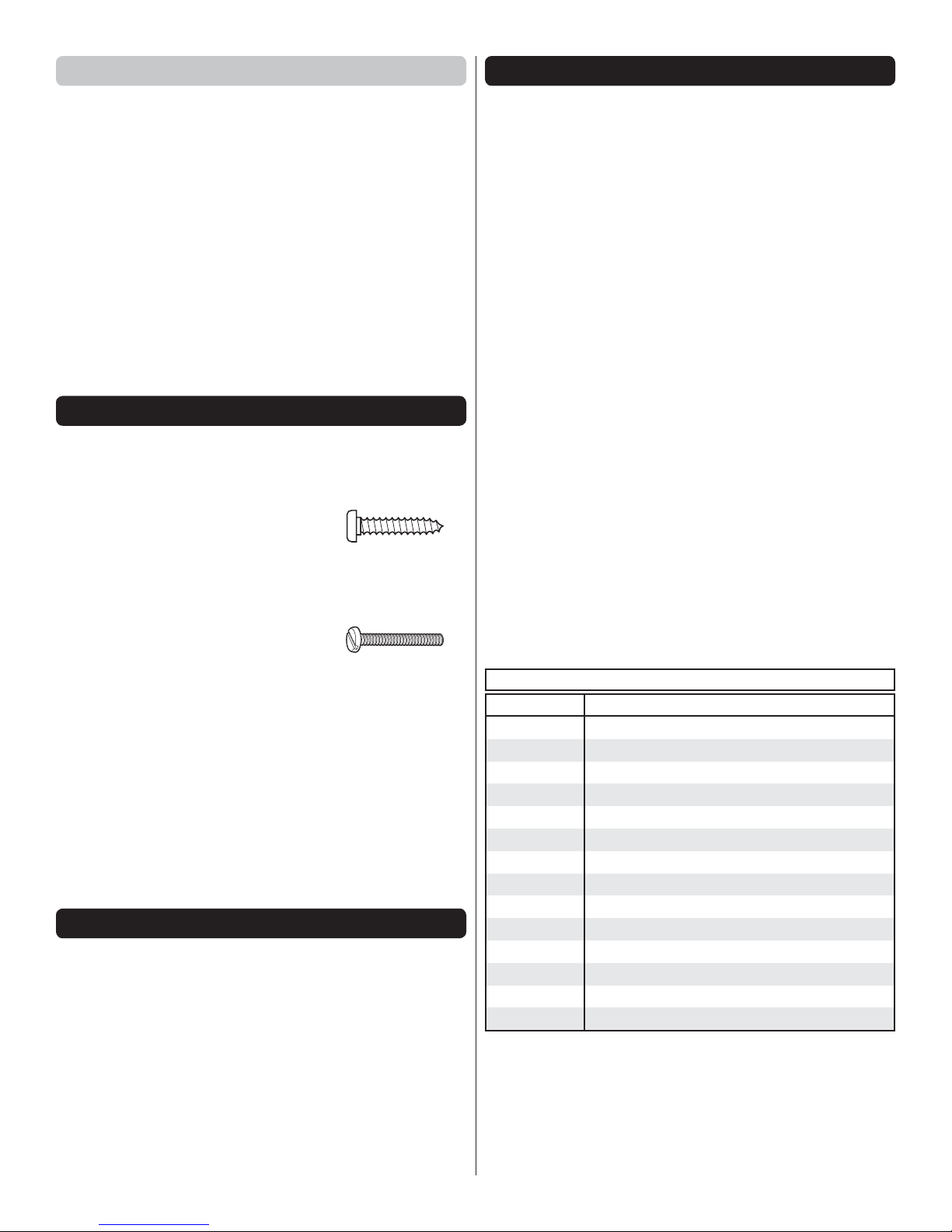
● There are three types of screws used in this kit:
Sheet Metal Screws are designated by a number and a
length. For example #6 3/4" [19mm].
This is a number six screw
that is 3/4" [19mm] long.
Machine Screws are designated by a number,
threads per inch, and a length. For example
4-40 3/4" [19mm].
This is a number four screw
that is 3/4" [19mm] long with
forty threads per inch.
● When you see the term test fi t in the instructions, it means
that you should fi rst position the part on the assembly
without using any glue, then slightly modify or custom
fi t the part as necessary for the best fi t.
● Whenever the term glue is written you should rely upon
your experience to decide what type of glue to use. When
a specifi c type of adhesive works best for that step, the
instructions will make a recommendation.
● Photos and sketches are placed before the step they refer
to. Frequently you can study photos in following steps to
get another view of the same parts.
KIT INSPECTION
Before starting to build, take an inventory of this kit to make
sure it is complete, and inspect the parts to make sure they
are of acceptable quality. If any parts are missing or are not
of acceptable quality, or if you need assistance with assembly,
contact Product Support. When reporting defective or missing
parts, use the part names exactly as they are written in the
Kit Contents list.
Great Planes Product Support
3002 N Apollo Drive, Suite 1 Ph: (217) 398-8970, ext. 5
Champaign, IL 61822 Fax: (217) 398-7721
E-mail: airsupport@greatplanes.com
Replacement parts for the Great Planes Curtiss P-6E Hawk
are available using the order numbers in the Replacement
Parts List that follows. The fastest, most economical service
can be provided by your hobby dealer or mail-order company.
To locate a hobby dealer, visit the Hobbico web site at www.
hobbico.com. Choose “Where to Buy” at the bottom of the menu
on the left side of the page. Follow the instructions provided
on the page to locate a U.S., Canadian or International dealer.
If a hobby shop is not available, replacement parts may also
be ordered from Tower Hobbies at www.towerhobbies.com,
or by calling toll free (800) 637-6050.
Parts may also be ordered directly from Hobby Services by
calling (217) 398-0007, or via facsimile at (217) 398-7721, but
full retail prices and shipping and handling charges will apply.
Illinois and Nevada residents will also be charged sales tax. If
ordering via fax, include a Visa® or MasterCard® number and
expiration date for payment.
Mail parts orders Hobby Services
and payments by 3002 N Apollo Drive, Suite 1
personal check to: Champaign IL 61822
Be certain to specify the order number exactly as listed in the
Replacement Parts List. Payment by credit card or personal
check only; no C.O.D.
If additional assistance is required for any reason contact
Product Support by e-mail at productsupport@greatplanes.
com, or by telephone at (217) 398-8970.
REPLACEMENT PARTS LIST
Order No. Description
GPMA3425
GPMA3426
GPMA3427
GPMA3428
GPMA3429
GPMA3430
GPMA3431
GPMA3432
GPMA3433
GPMA3434
GPMA3435
GPMA3436
GPMA3437
GPMA3438
Fuselage
Top Wing
Bottom Wing
Tail Surface Set
Cowl
Landing Gear
Wheel Pants
Hatch
Cabane Set
Interplane Struts
Bracket Set
Windshield
Decals
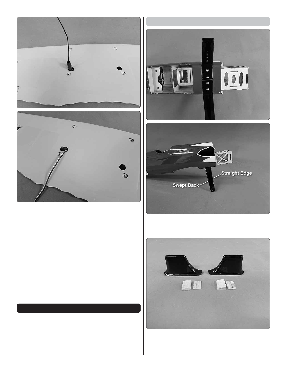
Landing Gear Fairings
4
Page 5
KIT CONTENTS
1
2
3
15
16
14
12
1313
11
4
17
10
PREPARATIONS
1. If you have not done so already, remove the major parts of
the kit from the box and inspect for damage. If any parts are
damaged or missing, contact Product Support at the address or
telephone number listed in the “Kit Inspection” section on page 4.
2. Use a covering iron with a covering sock on medium heat to
tighten the covering on the wings, fuselage, etc. if necessary.
Apply pressure over sheeted areas to thoroughly bond the
covering to the wood.
3. Test pull all pre-hinged surfaces.
1.
Lower Wing
2.
Upper Wing
3.
Fuselage
4.
5
6
8
9
7
Hatch
5.
Fin and Rudder
6.
Stab and Elevator
7.
"N" Struts
8.
Brackets
9.
Cabane Struts
10.
Cowl
11.
Wheel Pants
12.
Turtle Deck Fairing
13.
Landing Gear
14.
Wheels
15.
Tail Wheel Wire and Tail Wheel
16.
Landing Gear Fairings
17.
Windshield
ASSEMBLE THE WINGS
When working on the ailerons, do the right half of the
top wing fi rst, so your work matches the photos the fi rst
time through.
Install the Aileron Servos & Pushrods
1. Remove the servo cover from the wing.
❏ ❏
2. Inside the servo bay a string is taped. Carefully remove
❏ ❏
the tape and leave the loose end of the string in the servo bay.
3. Remove three of the arms from a four arm servo.
❏ ❏
Center the servo and install the arm to the servo, securing
it with the servo screw. Install the grommets and eyelets on
the servo.
5
Page 6
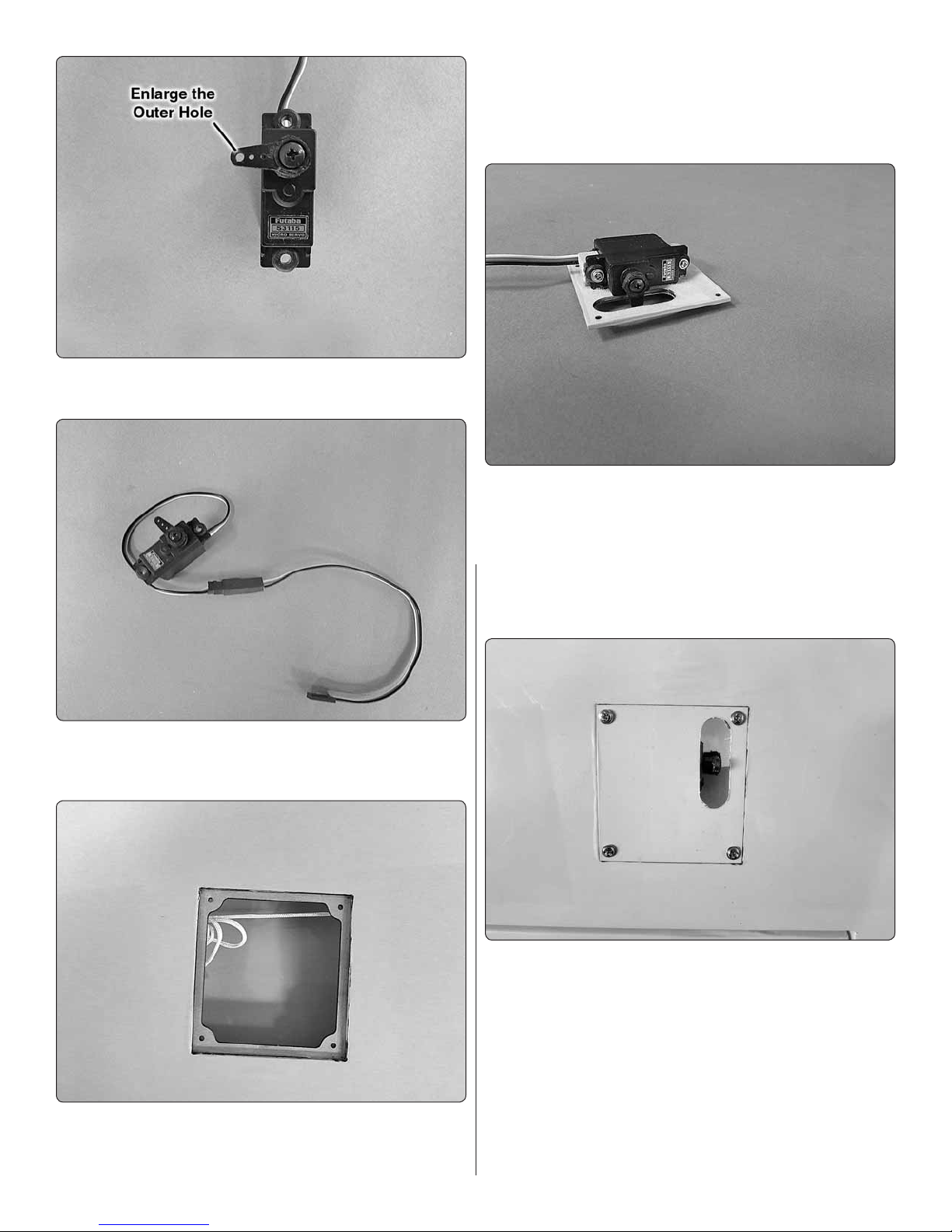
4. Enlarge the outer hole in the servo arm with a 5/64"
❏ ❏
[2mm] drill bit.
7. Place your servo onto the servo hatch, positioning it
❏ ❏
so that the control horn is centered in the opening in the hatch.
Glue two 9/32" x 3/8" x 3/8" [7 x 10 x 10mm] wood blocks to
the hatch, positioning the servo between the wood mounting
blocks with 5 minute epoxy.
8. After the glue has hardened place the servo between
❏ ❏
the blocks. Drill a 1/16" [1.6mm] hole through the servo
mounting tabs, into the wood blocks. Using the servo mounting
screws that came with the servos, install and then remove
the servo mounting screws. Apply a couple of drops of thin
CA glue into the holes to harden the threads. When the glue
has hardened, install the servo to the hatch with the servo
mounting screws.
5. Install a 9" [229mm] servo extension onto the servo.
❏ ❏
Be sure to secure the leads together with a piece of heat shrink
tubing, tape or some other method for securing the leads.
6. Tie the string from inside the servo bay to the end
❏ ❏
of the servo lead. Pull the lead through the wing, exiting out
through the hole at the center section of the wing.
9. Install and then remove a #2 x 3/8" [ 2 x 10mm] washer
❏ ❏
head screw into the four laser cut holes in the fl ange around
the servo hatch opening. Apply a drop of thin CA glue into
each of the four holes to harden the threads. Once the glue
has hardened, secure the hatch to the wing with four of the
#2 x 3/8" [2 x 10mm] washer head screws.
6
Page 7
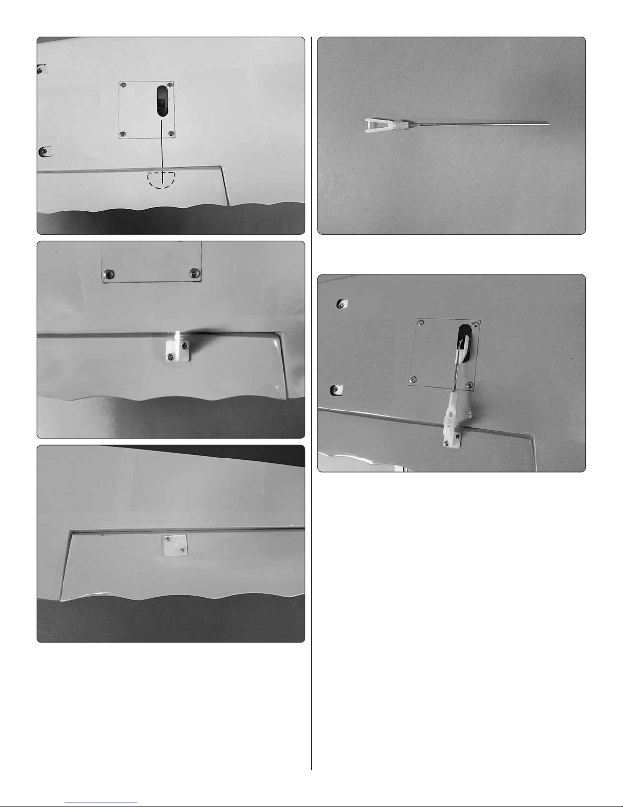
11. Thread a nylon clevis, 20 turns, onto a 6" [152mm]
❏ ❏
wire pushrod.
12. Slide a silicone clevis retainer over the clevis and
❏ ❏
install the clevis into the outer hole in the aileron control
horn. With the aileron servo and the aileron centered, mark
the aileron pushrod where it crosses the aileron servo arm.
Make a 90° bend at the mark. Cut the pushrod 3/8" [9.5mm]
past the bend. Attach the pushrod to the aileron servo arm
with a nylon Faslink.
10. Locate a nylon control horn. Cut the nylon mounting
❏ ❏
plate from the horn. Place the control horn onto the aileron
in line with the servo arm and positioned on the hardwood
plate. Mark the location of the mounting holes in the servo
horn onto the aileron. Drill a 5/64" [2mm] hole through the
aileron on each of the marks you just made. Secure the horn
to the aileron with two 1/16" x ½" machine screws and the
nylon back plate.
13. Repeat steps 1-11 for the left wing panel.
❏
7
Page 8
Install the Main Landing Gear
14. When installing the servo in the left half of the wing
❏
you may wish to have the extension exit the wing through the
same hole as the right aileron. This may be helpful in hiding
the leads as they extend into the fuselage. If you decide to
have both leads exit the same hole, you may need to use a
slightly longer servo lead and you will likely need to enlarge
the hole to make room for the dual servo lead. Either way
you choose to proceed, connect the two servos with a dual
servo extension (“Y” harness). Secure the extension with tape,
shrink tubing or some other method to secure the connection.
ASSEMBLE THE FUSELAGE
Before beginning the work on the fuselage you may wish to
remove the fuselage hatch. The hatch is held in place with
two magnets at the rear of the hatch. Lift the hatch from the
rear and remove it from the fuselage.
1. Attach the two main landing gear legs to the fuselage
❏
with four 4-40 x 5/8" [3.5 x 16mm] screws, #4 lock washers and
#4 fl at washers. Apply a drop of threadlocker to each screw.
2. Locate the two landing cuffs and the two sets of shaped
❏
wood parts.
8
Page 9

3. If you look closely at the wood parts you will see one
❏
part is thin and fl at, and the other is shaped. Glue the fl at
wood part on the front side of the landing gear as shown.
The shaped wood part should be glued to the back side of
the landing gear with the thickest portion of the shaped piece
towards the top of the landing gear.
4. Test fi t the landing gear cuff to the landing gear. When
❏
you are satisfi ed with the fi t of the cuff over the landing gear,
glue the cuff in place to the wood parts.
You will complete the installation of the wheels and wheel pants
in a later step. Installing the landing gear legs now will make
handling the fuselage easier during the assembly of the wings.
Install the Wings, Cabanes & Struts
1. Locate the nylon pin. Glue it into the hole in the leading
❏
edge of the bottom wing.
9
Page 10

2. Install the lower wing to the fuselage with two ¼-20 x 2"
❏
[51mm] nylon wing bolts.
5. Install the struts to the bottom wing with 4-40 x 5/16" [3
❏
x 8mm] machine screws, #4 lock washers and fl at washers.
3. Locate the two “N” Struts and the eight strut brackets.
❏
Separate the brackets into two groups of four, making sure
the angles of the brackets in each group match.
4. Install two of the lower brackets into the bottom of an “N”
❏
strut with a 4-40 x 5/16" [3 x 8mm] machine screw and a 4-40
lock nut. Look at the photo in step fi ve to help determine the
proper direction for the “N” strut. The top of the strut is slightly
wider than the bottom of the strut. The narrower end of the
strut fi ts the bottom wing. Repeat this for the upper brackets.
Do this for both struts.
6. Install the center cabanes to the bottom of the top wing.
❏
It is important that they are positioned properly or they will not
mate correctly to the fuselage. Examine the photos to help
you in placing them correctly onto the wing.
10
Page 11

7. Secure the top wing to the “N” struts with 4-40 x 5/16" [3
❏
x 8mm] machine screws, #4 lock washers and fl at washers.
After the struts are attached, work the center cabanes so that
they are resting in the pockets in the fuselage sides.
which cabane goes on each side of the fuselage. On the
marks you made in the fuselage, drill a 3/32" [2.5mm] hole
through the fuselage sides. Insert and remove a 1/8" x 3/8"
washer head screw into each of the four holes. Apply a drop
of thin CA into each of the holes to harden the threads. After
the glue has hardened, secure the cabanes to the fuselage
and re-install the top wing.
Install the Tail Assembly
8. The next step is to mark the mounting holes in the
❏
fuselage for the cabane screws. With the “N” struts attached
to the wings, the top and bottom wing should be properly
positioned without any twists. The cabanes should now be
resting properly in the fuselage. The cabanes may not be fully
into the mounting pockets in the fuselage. That is acceptable.
If needed you can press down on the wing a bit to get the
cabanes in the pocket, but be careful not to distort the wings.
Using a pen, mark where the mounting holes for the cabanes
need to be drilled.
1. Located at the back of the fuselage in the slot for the
❏
horizontal stabilizer, a small wood block has been temporarily
installed to protect the fuselage during shipping. Remove the
block with a hobby knife.
9. Remove the top wing from the struts and remove the
❏
center cabanes from the wing. Make sure to keep track of
2. Slide the stabilizer and fi n into the slots at the back
❏
of the fuselage. Using a felt tip pen, outline the shape of the
fuselage on the stab and fi n. Remove them from the fuselage.
11
Page 12

3. Using a sharp hobby knife, cut the covering inside the
❏
lines you traced onto the parts. When cutting the covering
you must be careful to cut only through the covering, not
into the wood. The best way to do this is as shown in the
following “Hot Tip”.
HOW TO CUT COVERING FROM BALSA
Use a soldering iron to cut the covering from the stab. The
tip of the soldering iron doesn’t have to be sharp, but a fi ne
tip does work best. Allow the iron to heat fully.
4. Look closely at the leading edge of the elevator. You
❏
will notice on one side there is a plywood plate. This is the
bottom of the stabilizer and elevator. Be sure you position the
stabilizer properly in the next couple of steps.
5. Apply 30 minute epoxy to both sides of the horizontal
❏
stabilizer and insert it into the slot in the back of the fuselage.
Clean excess epoxy with a paper towel and rubbing alcohol.
Work quickly and move onto the next few steps.
Use a straightedge to guide the soldering iron at a rate that
will just melt the covering and not burn into the wood. The
hotter the soldering iron, the faster it must travel to melt a
fi ne cut. Peel off the covering.
6. Locate the tail wheel wire. Apply a drop of oil onto the
❏
wire where it passes through the nylon bearing. This will
prevent glue from getting into the bearing.
12
Page 13

7. Apply a small amount of glue to the end of the tail wheel
❏
wire and then slide the wire into the hole in the leading edge
of the rudder.
horn onto the elevator with the holes centered over the hinge
line. Mark the location of the screw holes. Drill a 3/32" [2.5mm]
hole through the elevator on each of the marks. Secure the
horn to the elevator with two 1/16" x ½" machine screws and
the nylon back plate.
4. Remove the elevator pushrod from the fuselage. Bend
❏
the wire as shown to allow the wire to be aligned with the
pushrod exit in the fuselage when the clevis is attached to
the control horn.
8. Apply epoxy to both sides of the fi n where you removed
❏
the covering and apply a small amount of glue to the nylon
bearing. Insert the fi n into the slot in the fuselage, locking
it into the slot in the horizontal stabilizer. Clean any excess
glue with a paper towel moistened with rubbing alcohol. Make
sure the stabilizer is aligned with the wings and then set the
assembly aside until the glue has hardened.
Install the Elevator, Rudder
Servos and Receiver
1. Remove the top wing. This will provide access to the
❏
servo compartment.
2. Install a clevis and clevis keeper onto the threaded end
❏
of the two 20" [508mm] pushrod wires the same as was done
for the ailerons.
3. Slide the wire into the pushrod exit on the left side of
❏
the fuselage. Using the pushrod as a guide, position a control
5. Repeat step 3 for the rudder pushrod wire. Note: the
❏
rudder pushrod will insert into the pushrod exit without bending
the wire.
13
Page 14

6. Remove three of the arms from a four arm servo horn.
❏
Drill the outer hole of the arm with a 5/64" [2mm] drill. Place
the elevator servo arm outer hole in line with the pushrod wire.
Drill a 1/16" [1.6mm] hole through the servo mounting tabs,
into the plywood. Using the servo mounting screws that came
with the servos, install and then remove the servo mounting
screws. Apply a couple of drops of thin CA glue into the holes
to harden the threads. When the glue has hardened install
the servo into the servo tray.
7. With the elevator servo and the elevator centered, mark
❏
the elevator pushrod where it crosses the elevator servo arm.
Make a 90° bend at the mark. Cut the pushrod 3/8" [9.5mm]
past the bend. Attach the pushrod to the elevator servo arm
with a nylon Faslink.
tray as shown. Plug the elevator and rudder servos into the
appropriate channels on your receiver.
Install the Motor, ESC and Cowl
8. Repeat step 7 for the rudder servo.
❏
9. Apply a 1-1/4" [32mm] length of self-adhesive hook
❏
and loop material to the receiver and attach it to the servo
1. Cut a piece of the adhesive backed Velcro to fi t the
❏
speed control and apply one side of it to one side of the
speed control and the other half to the bottom of the battery
tray in the fuselage.
14
Page 15

2. Install a 4" [102mm] adhesive backed strip of Velcro in
❏
the battery compartment in the top of the fuselage.
5. Position the cowl over the motor, centering the motor with
❏
the hole in the front of the cowl. Be sure the motor prop fl ange
extends beyond the front of the cowl to allow for clearance
for the propeller.
6. When you are satisfi ed with the position of the cowl, on
❏
the lines you drew measure forward 2" [51mm] and make a
mark on the cowl. Drill a 5/64" [2mm] hole through one of the
marks and into the cowl mounting block. Install one of the
3/32" x 3/8" [2.5 x 10mm] washer head screws in the hole you
drilled. Re-check the cowl position and then drill on another
mark and install a screw. Repeat this for all four holes. After
you have drilled and inserted the screws, remove the cowl
and the masking tape from the fuselage. Apply a couple of
drops of thin CA into each of the holes you drilled to harden
the threads. Once the glue has hardened re-install the cowl.
3. Assemble your motor following the instructions that came
❏
with it. Install the motor to the fi rewall with four 4-40 x 3/8" [3
x 10mm] machine screws, #4 [3mm] lock washers and #4
[3mm] fl at washers. Be sure to apply a drop of thread locker
to the threads on each screw. Plug the leads from the motor
into the speed control. Follow the instructions with your motor
for determining the proper rotation for the motor.
4. Apply a 2-1/2" [64mm] piece of masking tape on the
❏
fuselage in line with each of the four cowl mounting blocks.
Draw a line from the center of each block back 2" [51mm].
7. Install the prop to the motor shaft. Once you are satisfi ed
❏
everything fi ts, remove the prop. (When you set up the
electronics it is safer to do so without the prop in place).
15
Page 16

Install the Wheels and Wheel Pants
3. Slide the right side wheel pant over the wheel. Secure
❏ ❏
the wheel pant to the landing gear with two 2-56 x ½" [13mm]
screws, #2 lock washers and #2 fl at washers. Repeat this for
the remaining wheel pant.
1. Install an axle to each of the landing gear legs with
❏ ❏
the axle nut. When installing the axle be sure the fl at spot on
the axle is towards the ground.
2. Install a 4-40 set screw into two 3/16" [4.8mm] wheel
❏ ❏
collars. Apply a drop of thread locker onto the set screws
before installing them into the wheel collar. Slide one wheel
collar onto the axle followed by the wheel and the second
wheel collar. Center the wheel on the axle and then tighten
the set screws against the axle. The outer wheel collar set
screw should be tightened against the fl at spot on the axle.
Do this for both landing gear legs.
4. Install a 4-40 set screw into two 1/8" [3mm] wheel
❏ ❏
collars. Apply a drop of thread locker onto the set screws
before installing them into the wheel collar. Slide one wheel
collar onto the tail wheel wire followed by the wheel and the
second wheel collar. Center the wheel on the wire and then
tighten the set screws against the wire.
16
Page 17

Final Details
1. Glue the turtle deck in place to the top of the fuselage. A
❏
white aliphatic glue such as Formula 500 canopy glue works
well for this. Tape the turtle deck to the fuselage while the
glue is drying.
2. To complete the details of this airplane a windshield
❏
has been included. The windshield does make it a bit more
diffi cult to install the battery. Test fi t the battery and canopy to
determine if you want to install the windshield. The windshield
can be glued to the fuselage with the technique used for the
turtle deck.
4. To hide the servo lead coming from the top wing we
❏
found it was best to make a slot the width of the servo lead in
the fuselage as shown. You can attach the lead from the top
wing to the cabane with tape or heat shrink tubing. Plug the
aileron servo lead into the extension in the receiver.
5. Install a pilot fi gure if desired.
❏
Apply the Decals
The following photographs and the box photographs show
the location of the decals on the airplane. Refer to these for
the exact placement of the decals. The following tips may be
useful for applying them.
3. Plug a 9" [229mm] servo lead into the appropriate
❏
channel on your receiver for the ailerons. Feed the lead into
the battery compartment.
17
Page 18

3. Use a piece of soft balsa or something similar to squeegee
FULL
THROTTLE
RUDDER
MOVES
RIGHT
ELEVATOR
MOVES DOWN
RIGHT AILERON
MOVES UP
LEFT AILERON
MOVES DOWN
4-CHANNEL RADIO SET UP (STANDARD MODE 2)
❏
remaining water from under the decal. Apply the rest of the
decals the same way
GET THE MODEL READY TO FLY
Note: If you have not re-installed the wings, install them now.
Check the Control Directions
1. Turn on the transmitter and receiver and center the trims.
❏
If necessary, remove the servo arms from the servos and
reposition them so they are centered. Reinstall the screws
that hold on the servo arms.
2. With the transmitter and receiver still on, check all the
❏
control surfaces to see if they are centered. If necessary, adjust
the clevises on the pushrods to center the control surfaces.
1. Be certain the model is clean and free from oily fi ngerprints
❏
and dust. Prepare a dishpan or small bucket with a mixture
of liquid dish soap and warm water—about one teaspoon of
soap per gallon of water. Submerse the decal in the soap and
water and peel off the paper backing. Note: Even though the
decals have a “sticky-back” and are not the water transfer type,
submersing them in soap & water allows accurate positioning
and reduces air bubbles underneath.
2. Position decals on the model. Holding the decal down,
❏
use a paper towel to wipe most of the water away.
3. Make certain that the control surfaces and the throttle
❏
respond in the correct direction as shown in the diagram. If any
of the controls respond in the wrong direction, use the servo
reversing in the transmitter to reverse the servos connected to
those controls. Be certain the control surfaces have remained
centered. Adjust if necessary.
18
Page 19

Set the Control Throws
Finish the Model
Use a ruler to accurately measure and set the control throw
of each control surface as indicated in the chart that follows.
If your radio does not have dual rates, we recommend setting
the throws at the low rate setting.
NOTE: The throws are measured at the widest part of the
elevators, rudder and ailerons.
These are the recommended control surface throws:
HIGHLOW
ELEVATOR
Up & Down
RUDDER
Right & Left
AILERONS
Up & Down
IMPORTANT: The Curtiss P-6E Hawk EP has been
extensively fl own and tested to arrive at the throws at
which it fl ies best. Flying your model at these throws will
provide you with the greatest chance for successful fi rst
fl ights. If, after you have become accustomed to the way
Curtiss P-6E Hawk EP fl ies, you would like to change the
throws to suit your taste, that is fi ne. However, too much
control throw could make the model diffi cult to control, so
remember, “more is not always better.”
3/8"
[10mm]
10°
3/8"
[10mm]
8°
7/16"
[11mm]
20°
5/8"
[16mm]
16°
5/8"
[16mm]
14°
3/4"
[19mm]
37°
1. Insert a fl ight battery in the fuselage and use Velcro to
❏
hold the battery in position. Do not connect the battery to the
ESC while balancing the model.
Balance the Model (C.G.)
More than any other factor, the C.G. (balance point) can
have the greatest effect on how a model fl ies, and may
determine whether or not your fi rst fl ight will be successful.
If you value this model and wish to enjoy it for many fl ights,
DO NOT OVERLOOK THIS IMPORTANT PROCEDURE.
A model that is not properly balanced will be unstable and
possibly unfl yable.
At this stage the model should be in ready-to-fl y condition with
all of the systems in place including the motor and battery,
landing gear, covering and paint, and the radio system.
1. Use a felt-tip pen or 1/8" [3mm]-wide tape to accurately
❏
mark the C.G. on the bottom of the top wing at the side of the
fuselage. The C.G. is located 3" [76mm] back from the leading
edge of the wing at the side of the fuselage.
This is where your model should balance for the fi rst fl ights.
Later, you may wish to experiment by shifting the C.G. up to
3/16" [5mm] forward or 1/8" [3mm] back to change the fl ying
characteristics. Moving the C.G. forward may improve the
smoothness and stability, but the model may then require
more speed for takeoff and make it more diffi cult to slow
for landing. Moving the C.G. aft makes the model more
maneuverable, but could also cause it to become too diffi cult
to control. In any case, start at the recommended balance
point and do not at any time balance the model outside the
specifi ed range.
19
Page 20

2. With the wing attached to the fuselage, all parts of the
❏
model installed (ready to fl y) and the battery installed, lift it
at the balance point you marked.
3. If the tail drops, the model is “tail heavy” and the battery
❏
pack and/or receiver must be shifted forward or weight must
be added to the nose to balance. If the nose drops, the model
is “nose heavy” and the battery pack must be shifted aft or
weight must be added to the tail to balance. If additional weight
is required, use Great Planes (GPMQ4485) “stick-on” lead. A
good place to add stick-on nose weight is to the motor box
(don’t attach weight to the cowl—it is not intended to support
weight). Begin by placing incrementally increasing amounts of
weight on the fuse over the motor box until the model balances.
Once you have determined the amount of weight required, it
can be permanently attached.
Charge the Batteries
Follow the battery charging instructions that came with your
radio control system to charge the batteries. You should always
charge your transmitter batteries the night before you go fl ying,
and at other times as recommended by the radio manufacturer.
Range Check
Ground check the operational range of your radio before the
fi rst fl ight of the day. With the transmitter antenna collapsed
and the receiver and transmitter on, you should be able to walk
at least 100 feet away from the model and still have control.
Have an assistant stand by your model and, while you work the
controls, tell you what the control surfaces are doing. Repeat
this test with the motor running at various speeds with an
assistant holding the model, using hand signals to show you
what is happening. If the control surfaces do not respond
correctly, do not fl y! Find and correct the problem fi rst. Look
for loose servo connections or broken wires, corroded wires
on old servo connectors, poor solder joints in your battery
pack or a defective cell, or a damaged receiver crystal from
a previous crash. The problem may be the location of the
antenna. The antenna should be as far away from the ESC
and battery as possible.
MOTOR SAFETY PRECAUTIONS
NOTE: Do not rely upon the adhesive on the back of the
lead weight to permanently hold it in place. Over time the
adhesive may soften and cause the weight to fall off. Use #2
sheet metal screws, RTV silicone or epoxy to permanently
hold the weight in place.
4. IMPORTANT: If you found it necessary to add any weight,
❏
recheck the C.G. after the weight has been installed.
Balance the Model Laterally
1. With the wing level, have an assistant help you lift the
❏
model by the engine propeller shaft and the bottom of the
fuse under the TE of the fi n. Do this several times.
2. If one wing always drops when you lift the model, it means
❏
that side is heavy. Balance the airplane by adding weight to the
other wing tip. An airplane that has been laterally balanced
will track better in loops and other maneuvers.
PREFLIGHT
Identify Your Model
No matter if you fl y at an AMA sanctioned R/C club site or if
you fl y somewhere on your own, you should always have your
name, address, telephone number and AMA number on or
inside your model. It is required at all AMA R/C club fl ying sites
and AMA sanctioned fl ying events. Fill out the identifi cation
tag on page 23 and place it on or inside your model.
Failure to follow these safety precautions may result
in severe injury to yourself and others.
● Get help from an experienced pilot when learning to
operate electric motors.
● Use safety glasses when running electric motors.
● Do not run the motor in an area of loose gravel or
sand; the propeller may throw such material in your
face or eyes.
● Keep your face and body as well as all spectators
away from the plane of rotation of the propeller as you
run the motor.
● Keep these items away from the prop: loose clothing,
shirt sleeves, ties, scarfs, long hair or loose objects
such as pencils or screwdrivers that may fall out of
shirt or jacket pockets into the prop.
● The motor gets hot! Do not touch it during or right
after operation.
● When working on your plane, remove the propeller if
the motor battery will be connected.
● Always remove the motor battery from the plane when
charging.
● Follow the charging instructions included with your
charger for charging LiPo batteries. LiPo batteries can
cause serious damage if misused.
● Never leave a charging LiPo unattended!
20
Page 21

AMA SAFETY CODE EXCERPTS
CHECK LIST
Read and abide by the following excerpts from the Academy
of Model Aeronautics Safety Code. For the complete Safety
Code refer to Model Aviation magazine, the AMA web site or
the Code that came with your AMA license.
General
1) I will not fl y my model aircraft in sanctioned events, air shows,
or model fl ying demonstrations until it has been proven to be
airworthy by having been previously, successfully fl ight tested.
2) I will not fl y my model aircraft higher than approximately
400 feet within 3 miles of an airport without notifying the
airport operator. I will give right-of-way and avoid fl ying in the
proximity of full-scale aircraft. Where necessary, an observer
shall be utilized to supervise fl ying to avoid having models fl y
in the proximity of full-scale aircraft.
3) Where established, I will abide by the safety rules for the
fl ying site I use, and I will not willfully and deliberately fl y my
models in a careless, reckless and/or dangerous manner.
5) I will not fl y my model unless it is identifi ed with my name
and address or AMA number, on or in the model. Note: This
does not apply to models while being fl own indoors.
7) I will not operate models with pyrotechnics (any device that
explodes, burns, or propels a projectile of any kind).
Radio Control
1) I will have completed a successful radio equipment ground
check before the fi rst fl ight of a new or repaired model.
2) I will not fl y my model aircraft in the presence of spectators
until I become a qualified flier, unless assisted by an
experienced helper.
3) At all fl ying sites a straight or curved line(s) must be
established in front of which all fl ying takes place with the
other side for spectators. Only personnel involved with fl ying
the aircraft are allowed at or in the front of the fl ight line.
Intentional fl ying behind the fl ight line is prohibited.
4) I will operate my model using only radio control frequencies
currently allowed by the Federal Communications Commission.
5)
I will not knowingly operate my model within three miles
of any pre-existing fl ying site except in accordance with
the frequency sharing agreement listed [in the complete
AMA Safety Code].
9) Under no circumstances may a pilot or other person touch
a powered model in fl ight; nor should any part of the model
other than the landing gear, intentionally touch the ground,
except while landing.
During the last few moments of preparation your mind may
be elsewhere anticipating the excitement of the fi rst fl ight.
Because of this, you may be more likely to overlook certain
checks and procedures that should be performed before the
model is fl own. To help avoid this, a check list is provided to
make sure these important areas are not overlooked. Many
are covered in the instruction manual, so where appropriate,
refer to the manual for complete instructions. Be sure to
check the items off as they are completed (that’s why it’s
called a check list!).
1. Check the C.G. according to the measurements
❏
provided in the manual.
2. Be certain the battery and receiver are securely
❏
mounted in the fuse. Simply stuffi ng them into place
with foam rubber is not suffi cient.
3. Extend your receiver antenna and make sure it has a
❏
strain relief inside the fuselage to keep tension off the
solder joint inside the receiver.
4. Balance your model laterally as explained in
❏
the instructions.
5. Use threadlocking compound to secure critical fasteners
❏
such as the motor screws, wheel collar SHC screws
and screw-lock pushrod connectors, etc.
6. Add a drop of oil to the axles so the wheels will
❏
turn freely.
7. Make sure all hinges are securely glued in place
❏
before each fl ight.
8. Reinforce holes for wood screws with thin CA where
❏
appropriate (servo mounting screws, control horn
screws, etc.).
9. Confi rm that all controls operate in the correct direction
❏
and the throws are set up according to the manual.
10. Make sure there are silicone retainers on all the clevises
❏
and that all servo arms are secured to the servos with
the screws included with your radio.
11. Secure connections between servo wires and
❏
Y-connectors or servo extensions with vinyl tape, heat
shrink tubing or special clips suitable for that purpose.
12. Make sure any servo extension cords you may have
❏
used do not interfere with other systems (servo arms,
pushrods, etc.).
13. Balance your propeller (and spare propellers).
❏
14. Tighten the propeller nut and spinner.
❏
15. Place your name, address, AMA number and telephone
❏
number on or inside your model.
16. If you wish to photograph your model, do so before
❏
your fi rst fl ight.
17. Range check your radio when you get to the fl ying fi eld.
❏
21
Page 22

FLYING
Flight
The Curtiss P-6E Hawk is a great-fl ying model that fl ies
smoothly and predictably. It does not, however, possess the
self-recovery characteristics of a primary R/C trainer and
should be fl own only by experienced R/C pilots. We recommend
the Curtiss P-6E Hawk be fl own from hard surfaces or very
short grass fi elds.
CAUTION (THIS APPLIES TO ALL R/C AIRPLANES): If,
while fl ying, you notice an alarming or unusual sound such
as a low-pitched “buzz,” this may indicate control surface
fl utter. Flutter occurs when a control surface (such as an
aileron or elevator) or a fl ying surface (such as a wing or
stab) rapidly vibrates up and down (thus causing the noise).
In extreme cases, if not detected immediately, fl utter can
actually cause the control surface to detach or the fl ying
surface to fail, thus causing loss of control followed by an
impending crash. The best thing to do when fl utter is detected
is to slow the model immediately by reducing power, then
land as soon as safely possible. Identify which surface
fl uttered (so the problem may be resolved) by checking all
the servo grommets for deterioration or signs of vibration.
Make certain all pushrod linkages are secure and free of
play. If it fl uttered once, under similar circumstances it will
probably fl utter again unless the problem is fi xed. Some
things which can cause fl utter are; Excessive hinge gap;
Not mounting control horns solidly; Poor fi t of clevis pin in
horn; Side-play of wire pushrods caused by large bends;
Excessive free play in servo gears; Insecure servo mounting;
and one of the most prevalent causes of fl utter; Flying an
over-powered model at excessive speeds.
For reassurance and to keep an eye on other traffi c, it is a
good idea to have an assistant on the fl ight line with you. The
Curtiss P-6E Hawk with the recommended power system will
only require full throttle in short bursts for some aerobatic
maneuvers. Most aerobatic fl ight can be performed at around
1/3rd to ½ throttle. If you observe the fl ight of some of the best
aerobatic pilots, they very seldom use full throttle.
Take it easy with the Curtiss P-6E Hawk for the fi rst fl ight,
gradually getting acquainted with it as you gain confi dence.
Adjust the trims to maintain straight and level fl ight. After fl ying
around for a while, and while still at a safe altitude with plenty
of battery, practice slow fl ight and execute practice landing
approaches by reducing the throttle to see how the model
handles at slower speeds. Add power to see how she climbs
as well. Continue to fl y around, executing various maneuvers
and making mental notes (or having your assistant write them
down) of what trim or C.G. changes may be required to fi ne
tune the model so it fl ies the way you like. Mind your battery
power level, but use this fi rst fl ight to become familiar with your
model before landing. With most electric planes it is best to
have a timer set on your transmitter or a separate timer with
an alarm to alert you when the battery may be getting low.
This will require a few fl ights before determining the maximum
fl ight time you can achieve with the batteries. This will prevent
the downwind auto motor cutoff over the end of the fl ying fi eld.
With the plane properly trimmed you will want to get started
with some aerobatics. This plane is capable many aerobatic
maneuvers. Loops, rolls, inverted fl ight and spins are all within
the capability of the Curtiss P-6E Hawk
Takeoff
Before you get ready to takeoff, see how the model handles
on the ground by doing a few practice runs at low speeds on
the runway. Hold “up” elevator to keep the tail wheel on the
ground. If necessary, adjust the tail wheel so the model will
roll straight down the runway. If you need to calm your nerves
before the maiden fl ight bring the model back into the pits,
peak the battery and check all fasteners and control linkages
for peace of mind.
Remember to takeoff directly into the wind. When you’re
ready, point the model straight down the runway, hold a bit
of up elevator to keep the tail on the ground to maintain tail
wheel steering, then gradually advance the throttle. As the
model gains speed decrease up elevator allowing the tail to
come off the ground. One of the most important things to
remember with a tail dragger is to always be ready to apply
right rudder to counteract engine torque. Gain as much speed
as your runway and fl ying site will practically allow before
gently applying up elevator, lifting the model into the air. At
this moment it is likely that you will need to apply more right
rudder to counteract motor torque. Be smooth on the elevator
stick, allowing the model to establish a gentle climb to a safe
altitude before turning into the traffi c pattern.
Landing
To initiate a landing approach, lower the throttle while on the
downwind leg. Allow the nose of the model to pitch downward
to gradually bleed off altitude. Continue to lose altitude, but
maintain airspeed by keeping the nose down as you turn onto
the crosswind leg. Make your fi nal turn toward the runway (into
the wind) keeping the nose down to maintain airspeed and
control. Level the attitude when the model reaches the runway
threshold, modulating the throttle as necessary to maintain
your glide path and airspeed. If you are going to overshoot,
smoothly advance the throttle (always ready on the right rudder
to counteract torque) and climb out to make another attempt.
When you’re ready to make your landing fl are and the model
is a foot or so off the deck, smoothly increase up elevator until
it gently touches down. Once the model is on the runway and
has lost fl ying speed, hold up elevator to place the tail on the
ground, regaining tail wheel control. We fi nd that the airplane
lands best using high elevator rates, though you may not need
those rates for many of the maneuvers you perform in fl ight.
One fi nal note about fl ying your model. Have a goal or fl ight
plan in mind for every fl ight. This can be learning a new
maneuver(s), improving a maneuver(s) you already know,
or learning how the model behaves in certain conditions
(such as on high or low rates). This is not necessarily to
improve your skills (though it is never a bad idea!), but more
22
Page 23

importantly so you do not surprise yourself by impulsively
attempting a maneuver and suddenly fi nding that you’ve run
out of time, altitude or airspeed. Every maneuver should be
deliberate, not impulsive. For example, if you’re going to do a
loop, check your altitude, mind the wind direction (anticipating
rudder corrections that will be required to maintain heading),
remember to throttle back at the top, and make certain you
are on the desired rates (high/low rates). A fl ight plan greatly
reduces the chances of crashing your model just because
of poor planning and impulsive moves. Remember to think.
Have a ball! But always stay in control
and fl y in a safe manner.
GOOD LUCK AND GREAT FLYING!
Phone Number
AMA Number
City, State, Zip
Address
This model belongs to:
Name
23
Page 24

Entire Contents © 2014 Hobbico,® Inc. All rights reserved.
GPMA1164
 Loading...