

Page 1
WARRANTY
Great Planes
®
Model Manufacturing Co. guarantees this kit to be free from defects in both material and workmanship at the date of
purchase. This warranty does not cover any component parts damaged by use or modification. In no case shall Great Planes’ liability
exceed the original cost of the purchased kit. Further, Great Planes reserves the right to change or modify this warranty without notice.
In that Great Planes has no control over the final assembly or material used for final assembly, no liability shall be assumed nor
accepted for any damage resulting from the use by the user of the final user-assembled product. By the act of using the userassembled product, the user accepts all resulting liability.
If the buyer is not prepared to accept the liability associated with the use of this product, the buyer is advised to return this
kit immediately in new and unused condition to the place of purchase.
While this kit has been flight tested to exceed normal use, if the plane will be used for extremely high stress flying, such as racing, the
modeler is responsible for taking steps to reinforce the high stress points.
READ THROUGH THIS MANUAL BEFORE
STARTING CONSTRUCTION. IT CONTAINS
IMPORTANT WARNINGS AND INSTRUCTIONS
CONCERNING THE ASSEMBLY AND USE OF
THIS MODEL.
GPMZ0227 for GPMA1225/1226 V1.0© Copyright 2000
P.O. Box 788 Urbana, IL 61803 (217) 398-8970
INSTRUCTION MANUAL
A. R. F.
Almost Ready to Fly
Page 2

Important Safety Precautions .........................................2
Introduction ......................................................................2
Precautions.......................................................................2
Decisions You Must Make ...............................................3
Engine Selection..........................................................3
Preparations......................................................................3
Required Accessories ..................................................3
Building Supplies and Tools.........................................3
Optional Supplies Tools ...............................................3
General Inspection.......................................................3
Building Notes..............................................................3
Parts List......................................................................4
Metric Conversions ......................................................4
Wing Assembly.................................................................5
Wing Installation...............................................................7
Install the Tail Components.............................................8
Engine Installation .........................................................10
Prop and Spinner Installation........................................11
Mount the Landing Gear ................................................11
Radio Installation ...........................................................13
Throttle Pushrod Installation ........................................15
Fuel Tank Assembly and Installation ...........................15
Decal Application ...........................................................16
Control Throw Adjustment............................................16
Balance Your Model Laterally .......................................16
Balance Your Model (CG) ..............................................17
Preflight...........................................................................17
Charge the Batteries..................................................17
Balance the Propeller ................................................17
Find a Safe Place to Fly ............................................17
Ground Check the Model...........................................17
Range Check Your Radio ..........................................18
Engine Safety Precautions ........................................18
AMA Safety Precautions (excerpt) ...............................18
Flying...............................................................................19
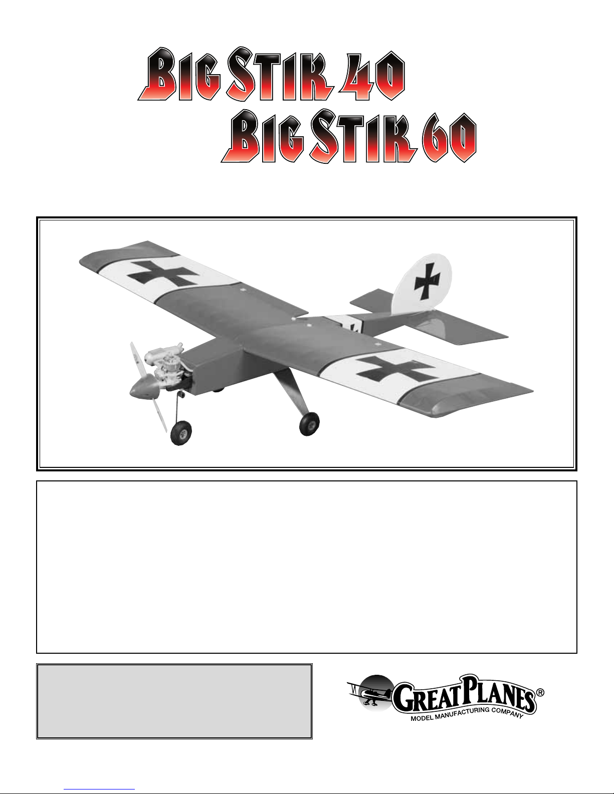
Your Big Stik ARF is not a toy, but rather a very sophisticated,
working model that functions very much like a full-size
airplane. Because of its realistic performance, the Big Stik, if
not assembled and operated properly, could possibly cause
injury to yourself or spectators and damage property.
To make your R/C modeling experience totally enjoyable,
we recommend that you get experienced, knowledgeable
help from an instructor with assembly and during your first
flights. You'll learn faster and avoid risking your model
before you're truly ready to solo. Your local hobby shop has
information about flying clubs in your area whose members
include qualified instructors.
You can also contact the national Academy of Model
Aeronautics (AMA) which has more than 2,500 chartered
clubs across the country. Through any one of them,
instructor training programs and insured newcomer training
are available. Contact the AMA at the address or toll-free
phone number below.
Academy of Model Aeronautics
5151 East Memorial Drive
Muncie, IN 47302-9252
Tele. (800) 435-9262
Fax (765) 741-0057
Or via the Internet at: http://www.modelaircraft.org
The Great Planes Big Stik ARF is an aircraft that lets you
progress from your trainer aircraft into a model that is not
only a good choice for improving your flying skills but is also
a great high performance, aerobatic model.
This plane is a good choice for a second airplane or as an
aerobatic trainer. We are sure that you will enjoy building and
flying the Big Stik ARF.
1. You must assemble the model according to the instructions.
Do not modify or alter the model, as doing so may result in an
unsafe or unflyable model. In a few cases the instructions may
differ slightly from the photos. In those instances the written
instruction should be considered as correct.
2. Take time to build straight, true and strong.
3. Use an R/C radio system that is in first-class condition
and a correctly sized engine and components throughout
the building process.
4. You must properly install the R/C radio system and other
components so that the model operates properly on the
ground and in the air.
5. You must test the operation of the model before every
flight to insure that all equipment is operating and you must
make certain that the model has remained structurally
sound. Be sure to check clevises or other connectors often
and replace them if they show signs of wear or fatigue.
PRECAUTIONS
INTRODUCTION
PROTECT YOUR MODEL, YOURSELF
& OTHERS...FOLLOW THIS
IMPORTANT SAFETY PRECAUTION
TABLE OF CONTENTS
2
Page 3
Please inspect all parts carefully before starting to build!
If any parts are missing, broken or defective, or if you
have any questions about building or flying this airplane,
please contact us at (217) 398-8970. You can also check
our web site at www.greatplanes.com or e-mail your
questions to productsupport@greatplanes.com. If you
are calling for replacement parts, please have your kit
information on hand before calling.
Items in parentheses (GPMQ4243) are suggested part
numbers recognized by distributors and hobby shops and
are listed for your ordering convenience. GPM is the Great
Planes®brand , TOP is the Top Flite®brand, and HCA is the
Hobbico®brand.
❏ Four channel radio with five servos
❏ Engine - See Engine Selection above
❏ Propeller (Top Flite
®
Power Point®–Refer To Your
Engine’s Instructions For Proper Size)
❏ 6" servo extension (2)
❏ “Y” connector (1) when using a basic 4 channel radio
These are the building tools that are required. We
recommend Great Planes Pro™CA and Epoxy glue.
❏ 2 oz. Pro CA (Thin, GPMR6003)
❏ 2 oz. Pro CA+ (Medium, GPMR6009)
❏ 6-Minute Pro Epoxy (GPMR6045)
❏ 30-Minute Pro Epoxy (GPMR6047)
❏ Epoxy Brushes (GPMR8060)
❏ Mixing Sticks (GPMR8055)
❏ Hobby Knife (TOWR1010), #11 blades (TOWR1015)
❏ String
❏ Builders Triangle Set (HCAR0480)
❏ Masking Tape (TOPR8018)
❏ 1/4" Latex Foam Rubber Padding (HCAQ1000)
❏ Paper Towels
❏ Felt tip pen
❏ Drill Bits: 1/16" (1.5mm), 5/64" (2mm), 3/32"
(2.4mm), 5/32" (4mm), 11/64" (4.4mm), 1/8" (3mm),
1/4" (6mm), #8 (5.2mm), #36 (2.8mm)
❏ Sealing Iron (TOPR2100)
❏ Heat Gun (TOPR2000)
❏ Switch and Charge Jack (GPMM1000)
❏ Fuel Filler Valve (GPMQ4160)
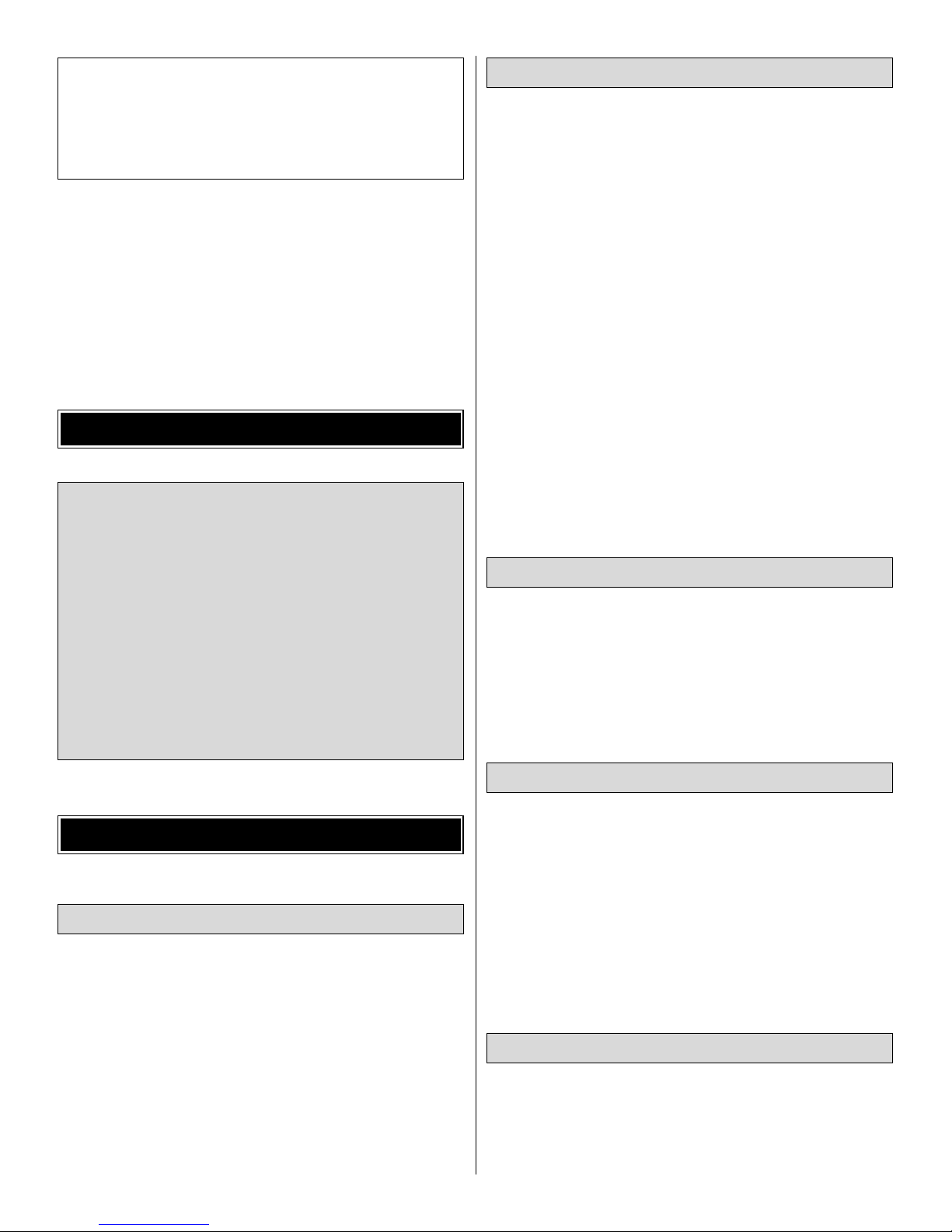
Remove the fuselage, wing panels, rudder assembly and
stabilizer assembly from their bags. Inspect all items closely
to check for any damage.
Your Big Stik ARF is covered with high quality Top Flite
MonoKote®covering. If any of the covering has loosened,
use a heat gun or sealing iron to tighten it.
During the construction we often refer to the “top” or
“bottom” of the model or a part of the model. It is understood
that the “top” or “bottom” of the model is as it would be when
the airplane is right side up and will be referred to as the
“top” even if the model is being worked on upside-down.
Building Notes
General Inspection
Optional Supplies & Tools
Building Supplies & Tools
Required Accessories
PREPARATIONS
Engine Selection
There are several engines that will work well in your Big
Stik ARF.
For the .40 Big Stik we recommend a 2-stroke engine
such as the O.S.®LA .40, O.S. .40 FX, O.S. .46 FS or the
SuperTigre®G40. For unsurpassed power and realistic
sound, an O.S. FS-52 can't be beat.
For the .60 Big Stik we recommend a 2-stroke engine
such as the O.S. LA .65, O.S. .61 FX or the SuperTigre
G61. If you prefer a four stroke engine the O.S.FS-70 or
O.S. FS-91 are both good choices.
DECISIONS YOU MUST MAKE
Note: We as the kit manufacturer, provide you with a top
quality kit and great instructions, but ultimately the quality of
your finished model depends on how you build it; therefore,
we cannot in any way guarantee the performance of your
completed model, and no representations are expressed or
implied as to the performance of your completed model.
3
Page 4
4
1/64" = .4mm
1/32" = .8mm
1/16" = 1.6mm
3/32" = 2.4mm
1/8" = 3.2mm
5/32" = 4mm
3/16" = 4.8mm
1/4" = 6.4mm
3/8" = 9.5mm
1/2" = 12.7mm
5/8" = 15.9mm
3/4" = 19mm
1" = 25.4mm
2" = 50.8mm
3" = 76.2mm
6" = 152.4mm
12" = 304.8mm
15" = 381mm
18" = 457.2mm
21" = 533.4mm
24" = 609.6mm
30" = 762mm
36" = 914.4mm
Metric Conversions
Parts List
Big Stik .40 (GPMA1225) Replacement Parts
If needed, replacement parts for your
Big Stik .40 ARF
are
available through your hobby supplier.
Wing Kit (A) ............................................................GPMA2187
Fuselage Kit (B) .....................................................GPMA2188
Tail Set (C) .............................................................GPMA2189
Landing Gear Set (D).............................................GPMA2190
Big Stik .60 (GPMA1226) Replacement Parts
If needed, replacement parts for your
Big Stik .60 ARF
are
available through your hobby supplier.
Wing Kit (A) ............................................................GPMA2191
Fuselage Kit (B) .....................................................GPMA2192
Tail Set (C) .............................................................GPMA2193
Landing Gear Set (D).............................................GPMA2194
Inch Scale
0" 1" 2" 3" 4" 5" 6" 7"
0 10 20 30 40 50 60 70 80 90 100 110 120 130 140 150 160 170 180
Metric Scale
Page 5
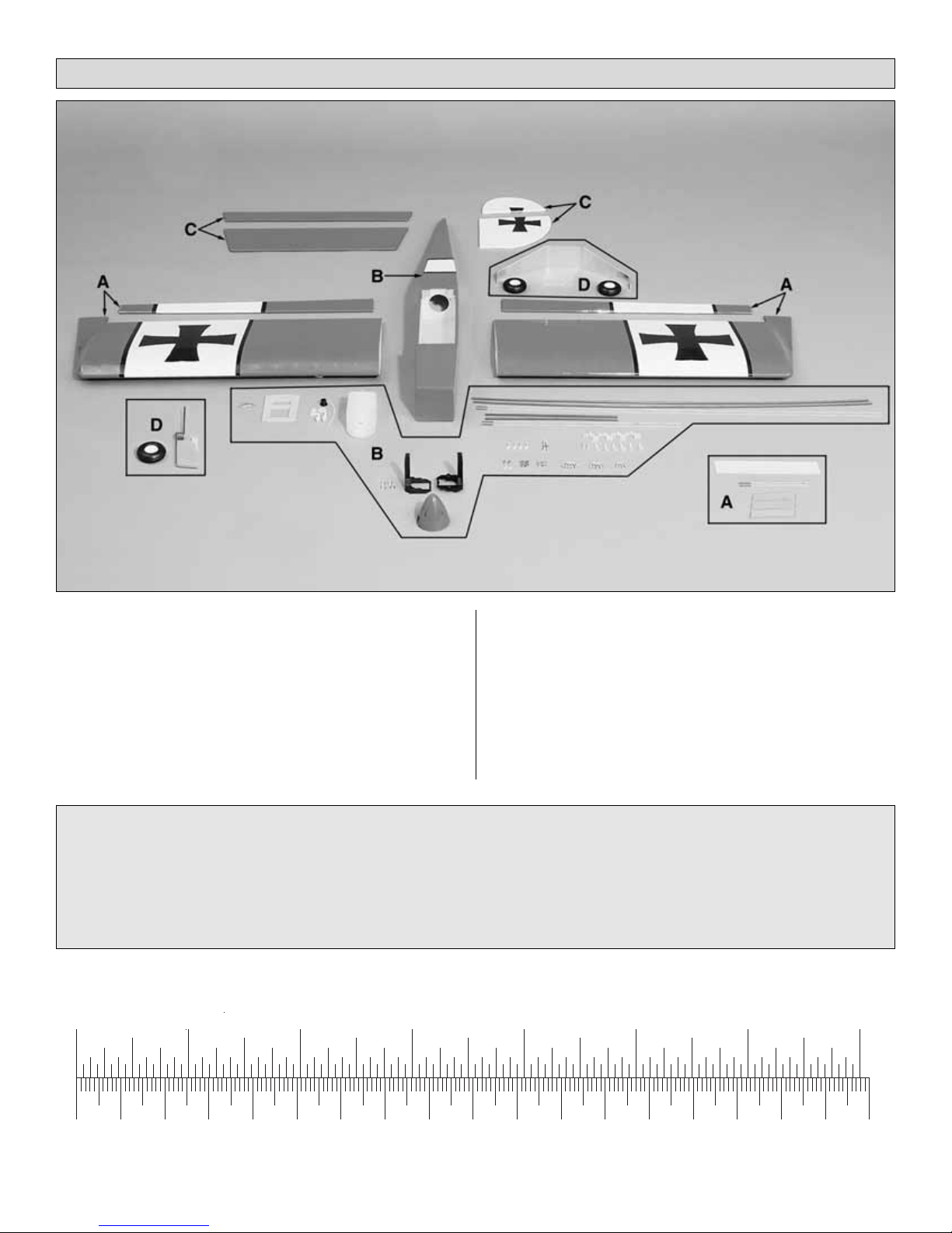
❏ 1. Locate the left and right aileron. Make a line 3/4"
(19mm) long on the leading edge of the aileron 1-1/2"
(38mm) from each end of the aileron. Make two additional
3/4" (19mm) lines, spacing them equally between the first
two lines.
❏ 2. From the 2" x 9" (50mm x 230mm) hinge material, cut
out your hinges. A total of 16 hinges will be needed for the
entire airplane. The hinges need to be cut to 3/4" x 1"
(19mm x 25mm).
❏ 3. Cut a 3/4" (19mm) slot in the leading edge of the
aileron at the previously marked locations. Trial fit the hinge
to make sure it goes in 1/2" (13mm). The slot can be done
with a hobby knife or the Great Planes Slot Machine™. The
Slot Machine is a real time saver when cutting slots for
hinges. If you are an avid modeler you will find this to be a
great tool to add to you shop!
❏ 4. Align the aileron in position at the trailing edge of the
wing. Be sure to leave at least a 1/6" (1.6mm) spacing
between the aileron and the outboard trailing edge of the
wing. When you are satisfied with the fit, mark the location
for the hinges on the trailing edge of the wing. Do this for the
left and right wing.
❏ 5. Install the aileron to the wing by applying 6 drops of
thin CA to the hinge. After the glue has cured, flex the aileron
back and forth a few times to loosen up the hinge. Pull on
the aileron to make sure that the aileron is firmly attached to
the wing. Repeat this step for the other wing.
❏ 6. Locate the servo bay in the bottom of each wing and
cut away the MonoKote to reveal the servo tray. Repeat for
the other wing.
TEMPORARY PIN
TO KEEP HINGE
CENTERED
THIN
CA
AND #11 BLADE
WITH HOBBY KNIFE
CUT HINGE SLOT
DRILL A 3/32" HOLE
1/2" DEEP, IN CENTER
OF HINGE SLOT
1"
1"
3/4"
WING ASSEMBLY
5
Page 6
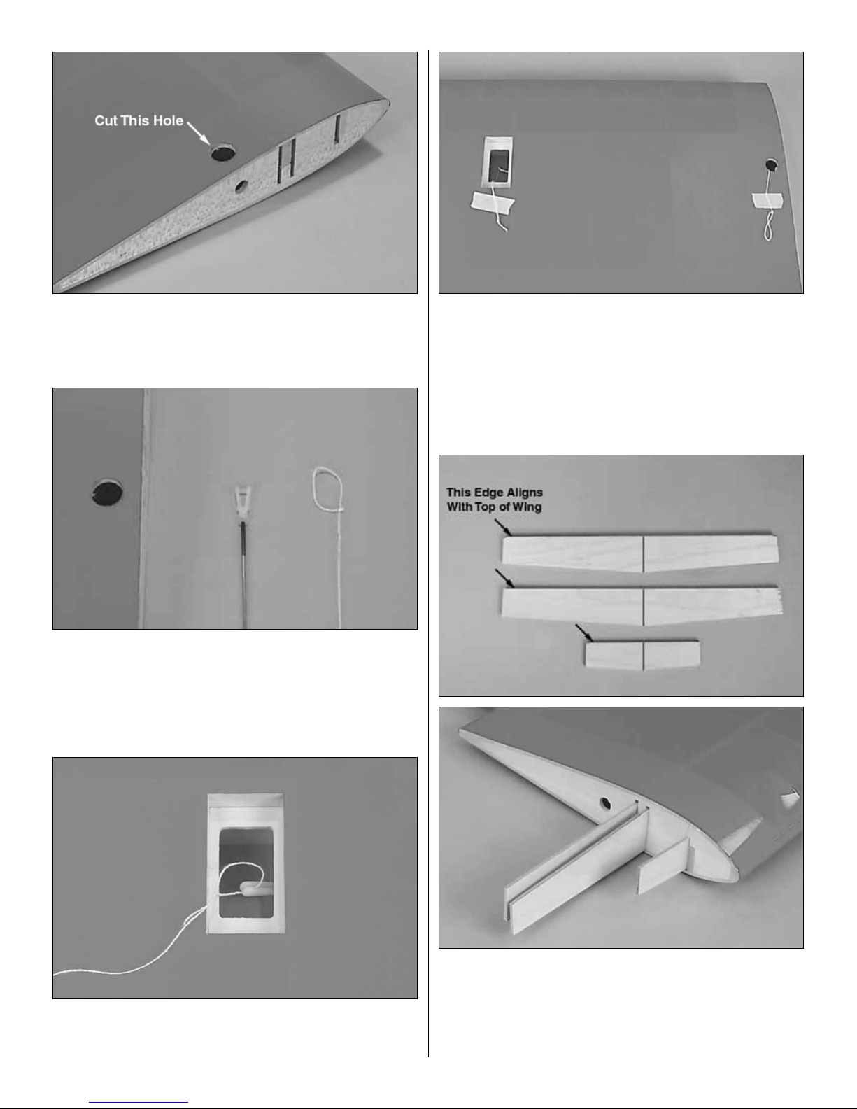
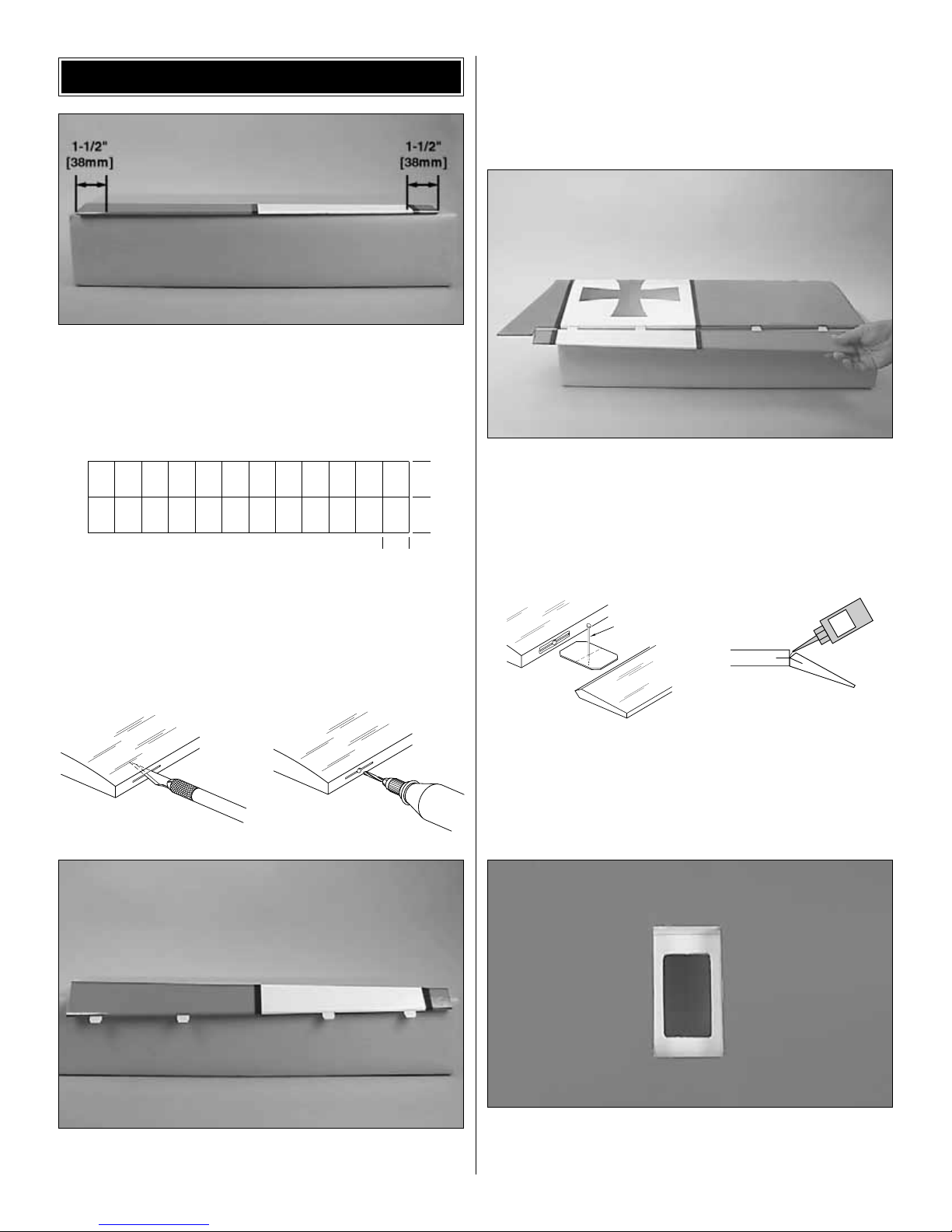
❏ ❏ 7. On the root rib there is a small hole. This is the hole
that the aileron servo wire will be fed through. Directly above
this hole make a 1/2” opening through the wing skin. This is
easily done with a Dremel® sanding drum.
❏ ❏ 8. Attach a clevis to one of the included pushrods. Tie
a loop onto a piece of string long enough to reach from the
servo bay to the hole you made in the wing skin. This string
will be used to assist pulling the servo wire through when we
get to the installation of the servos.
❏ ❏ 9. Insert the pushrod through the hole in the root rib
until the clevis shows in the servo bay. Put the string onto
the clevis and pull the string back through the hole.
❏ ❏ 10. Pull the string out through the opening in the
bottom of the wing skin. Using masking tape, tape the string
to the wing at the servo bay and the hole you pulled the
string through. Taping the string in place will prevent it from
falling back into the wing.
❏ 11. Repeat steps 7 - 10 for the other wing.
❏ 12. Locate the three wood joiners. Draw a center line on
each of them. Trial fit them into both wing halves making
sure that the straight edge of the joiner is aligned with the
top of the wing. Once you are satisfied with the fit, apply
6-minute epoxy to 1/2 of the joiner and one pocket of one of
the wing.
6
Page 7

❏ 13. After the 6-minute epoxy has cured, apply 30-minute
epoxy to the joiner and wing joiner pocket in the wing as well
as the root rib. Use masking tape to hold the two wing
halves together while the glue is drying.
❏ 1. Mark the center of the forward bulkhead that the
leading edge of the wing will attach to.
❏ 2. Place the wing in the wing saddle and align the center
of the wing on the mark you just made.
❏ 3. With the wing in the saddle and the center of the wing
aligned with the mark on the bulk head, drill two 1/4" (6mm)
holes into the wing. Drill the holes through the pre-drilled
holes that are in the bulk head.
❏ 4. Insert the 1/4" (6mm) wooden dowel into the leading
edge of the wing. The dowel should extend 1/4” (6mm)
beyond the LE of the wing. Trial fit the wing to the fuselage.
When you are satisfied with the fit, glue the dowels in place
in the wing with 6-minute epoxy.
❏ 5. When the dowels are secured to the wing they should
be flush with the bulkhead. If they are not, trim them flush.
Slightly round the tip of the dowels for easy installation of the
wing to the fuselage.
WING INSTALLATION
7
Page 8

❏ 6. Place the wing on the fuselage. Measure from the aft
center of the fuselage to one wing tip and record the
distance. Measure from the same point to the opposite wing
tip and compare it to the first measurement. If the
measurements are not the same, adjust the wing and remeasure until they are equal. Place a mark on the wing and
the fuselage so it can be repositioned accurately for the
following steps.
❏ 7. Make two additional reference marks on the fuselage,
aligning them with the center of the wing bolt blocks in
the fuselage.
❏ 8. With a 1/8" (3mm) drill bit, drill two pilot holes through
the wing and the wing bolt block. Use the reference marks
you made on the fuselage as a guide and the center the drill
on the wing plate.
❏ 9. Remove the wing. Use a #8 (5.2mm) or 13/64" drill bit
and drill through the pilot holes in the wing bolt blocks. Use
a 1/4 - 20 tap to thread the wing bolt blocks. After you have
the blocks tapped, wick some thin CA into the threads. After
the glue has dried, run the tap through the blocks once more
to clean out any excess glue.
❏ 10. Drill a 1/4" (6mm) hole through each of the pilot holes
in the wing. This will provide clearance for the wing bolts to
pass through the wing.
❏ 1. Cut 5 hinge slots in the horizontal stabilizer and the
elevator the same way you did for the ailerons. Test fit the
elevator to the horizontal stabilizer but do not glue them in
place yet.
❏ 2. Cut 3 hinge slots in the fin and the rudder the same
way you did for the ailerons. Test fit the fin to the elevator but
do not glue them in place yet.
INSTALL THE TAIL COMPONENTS
8
Page 9

❏ 3. Carefully cut away the covering from the bottom of the
fuselage in the stab saddle.
❏ 4. Mount the wing to the fuselage using the nylon bolts.
Lay the plane upside down and place the horizontal stabilizer
into position. Check the alignment as shown in the photo.
❏ 5. Stand back 8 to 10 feet (2.5 to 3 meters) and view the
model from the front and rear. The stabilizer tips should be
equally spaced in relation to the wing. If not, lightly sand the
high side of the stabilizer saddle to correct the problem.
Work slowly and check the alignment often.
❏ 6. When the alignment looks good, mark the outline of
the fuselage onto the stabilizer. Remove the stabilizer and
trim the covering 1/32" (.8mm) inside of the lines, being
careful not to cut into the underlying wood. Re-check
your alignment and glue the stabilizer to the fuselage with
6-minute epoxy.
CC
C = C
Horizontal Stabilizer
Wing
9
Page 10

❏ 7. Test fit the fin in the slot in the fuselage. When you are
satisfied with the fit, mark a line on both sides of the fin
where the top of the fuselage contacts the fin. Trim the
covering 1/32" (.8mm) inside of the lines.
❏ 8. When you are satisfied with the fit, use 6-minute epoxy
to glue the fin in position. Check the alignment of the fin to
the stabilizer with a triangle, then secure it in position with
masking tape until the epoxy has cured. Double-check the
alignment of the fin with the stabilizer while the epoxy cures.
❏ 9. Install the hinges in the stabilizer and elevator. Glue
the hinges to the elevator the same way you did with the
ailerons. Repeat this step for the rudder.
❏ 1. The top left and right corners of the firewall have pre-
drilled holes. These holes are for the fuel and pressure line to
pass through. Check to be sure that the holes are large enough
for your fuel line. If not, drill the holes to fit the fuel tubing.
❏ 2. Mix a small amount of 6-minute epoxy. Brush the
epoxy on the front of the firewall and let it cure. This will
fuelproof the firewall.
❏ 3. Cut the “spreader bar” from each Engine Mount half.
Carefully trim any extra material left by the spreader from
each mount half. The surfaces where the spreader bars were
attached must be smooth to allow the mount halves to fit
together. Trim the flashing off any rough edges if necessary.
❏ 4. Locate four 6-32 blind nuts and four 6-32 x 3/4" pan
head screws. Install the blind nuts onto the back side of the
firewall. Use the screws to attach the engine mount to the
firewall and to set the blind nuts.
ENGINE INSTALLATION
10
Page 11

❏ 5. Position the engine on the engine mount. Adjust the
mount as needed for your engine. Position the engine 4-1/4"
(106mm) from the front of the thrust washer to the firewall.
❏ 6. Use a #36 (2.8mm) drill bit and drill the four mounting
holes for the engine into the engine mount. After the holes
have been drilled, tap them with a 6-32 tap. The Great
Planes Dead Center™(GPMR8130) Engine Mount Hole
Locator works really well for this task.
❏ 1. Install the back plate, prop and prop washer onto the
engine crankshaft. Tighten the nut to hold everything in place.
❏ 2. Screw the spinner onto the backplate.
❏ 1. Locate the aluminum landing gear. Make a line 1/2"
(13mm) from the leading and trailing edge of the center portion
of the landing gear. Make four marks 3/4" (19mm) from the
bend of the gear. Where the lines intersect is the point where
you are going to drill the hole for the mounting bolts.
❏ 2. Drill four 5/32" (4mm) holes in the landing gear on the
four marks you just made.
❏ 3. Locate the aluminum landing gear under the plywood
landing gear plate. Center the landing gear over the
plywood plate. Then, using the landing gear as a template,
drill a 5/32" (4mm) hole through the fuselage in each of the
four holes in the landing gear.
MOUNT THE LANDING GEAR
PROP AND SPINNER INSTALLATION
11
Page 12

❏ 4. Re-drill the four holes in the fuselage to 11/64"
(4.4mm). Install four 6-32 blind nuts inside the fuselage in
the holes you drilled. Mount the landing gear to the fuselage
with four 6-32 x 3/4" (19mm) pan head screws.
❏ 5. Locate the wire nose gear, plastic steering arm, two
5/32" (4mm) wheel collars, one 6-32 x 1/4" (6mm) socket
head screw and one 6-32 x 1/2" (13mm) socket head screw.
Place one of the 5/32" (4mm) wheel collars into the center
of the plastic steering arm and hold it in place with the 6-32
x 1/2" (13mm) socket head screw. Insert the 6-32 x 1/4"
(6mm) socket head screw into the remaining wheel collar.
Place the steering arm onto the wire nose wheel wire and
insert the nose gear into the holes in the landing gear
mount. The steering arm should line up with the hole in the
firewall for the steering pushrod. Place the other wheel
collar on the top of the wire. Tighten the set screws. This will
hold the wire in place.
❏ 6. Locate two 5/32" (4mm) wheel collars and two 6-32 x
1/4" (6mm) set screws. Put the screws into the wheel collar.
Slide one collar onto the nose wheel axle, then your nose
wheel, and then the remaining collar. File a flat spot on the
nose gear wire where the wheel collar will be. Tighten the
set screws to hold the wheel on the center of the axle.
❏ 7. Locate four 8-32 nuts and two 8-32 x 1-1/4" (32mm)
socket head cap screws. These components are the axle for
the main gear. Install the 8-32 socket head cap screw through
the wheel. Install a nut on the screw and tighten it close to the
tire but not enough to prevent it from spinning freely on the
bolt. Insert the bolt through the hole in the landing gear. Place
the remaining 8-32 nut onto the bolt and tighten it against the
landing gear. Do the same for the other axle.
12
Page 13

❏ 1. Locate the two plywood servo plates. Position them as
shown in the photograph so that the forward plate is slightly
behind the former. The rear plate should be positioned behind
the forward plate the distance required for your servos. Leave
a 1/32" (.8mm) gap between the servos and the mounting
plates. When you are satisfied with the fit, use 6-minute epoxy
to glue the plates in position on the fuselage.
❏ 2. Use the following sequence for mounting the servos
into the servo tray.
❏ A. Install rubber grommets and brass eyelets in the
servos using the provided sketch.
❏ B. Test fit the servos in the tray.
❏ C. Mark servo hole locations on the tray, then drill
1/16" (1.5mm) pilot holes through each mark.
❏ D. Mount the servos with the screws provided with
your radio system. Notice the orientation when installing.
❏ 3. Following the manufacturer's recommendations, install
and hook up the three servos, the receiver, switch and battery
as shown in the photograph. Wrap the receiver and the
battery in foam and hold them in place by gluing small balsa
sticks (not included) above them. We added a Great Planes
Switch Mount and Charge Jack (GPMM1000, not included)
for convenience and ease of use at the field, installed on the
side of the fuselage.
❏ 4. Prepare a two arm style servo horn as follows but
don't install it on the servo until instructed to do so.
Note: The size and shape of servo horns varies from
manufacturer to manufacturer. The sketches and photos
show a typical radio installation with standard horns. All
standard servo horns should fit the Big Stik.
❏ A. Cut off two servo arms from four servo horns
included with your radio control set to make them into
"one arm" servo horns. Use your bar sander to remove
the remaining jagged edges left from the cut off arms.
❏ B. Enlarge the holes in the horns with a 5/64" (2mm) drill.
❏ C. Turn on your transmitter and receiver, then
position the aileron, rudder, elevator and throttle trim
tabs on your transmitter to the center. This is called
"centering" the servos and will allow you to place the
servo horns on the servos in a neutral position. Attach
the arms to the servos as shown in the following photos.
❏ 5. Prepare three one arm style servo horns following the
same step just done except cut off three unused arms.
RADIO INSTALLATION
13
Page 14

❏ 6. At the rear of the fuselage on both sides, cut away the
covering where the pushrod tubes exit the fuselage.
❏ 7. Install the rudder and elevator nylon control horn in
line with the servo pushrod. The rudder horn should be
mounted on the left side of the fuselage and the elevator
should be mounted on the right side of the fuselage. Hold
the horn in position and mark the location of the mounting
holes. Drill 3/32" (2.4mm) mounting holes through the
marks. Wick two to three drops of thin CA into the holes to
harden the underlying balsa, then re-drill the holes. Attach
the horns using #2 x 1/2" (13mm) Screws and Nylon Nut
Plates. Do not over-tighten the screws, crushing the
underlying balsa.
❏ 8. Locate the two longest threaded wire pushrods and
screw a nylon clevis on each one approximately 14 turns.
Place a silicone retainer over each of the clevises. Insert
the pushrod into the plastic tube. Attach the clevis to the
control horn.
❏ 9. Mark the pushrod where it crosses the servo arm.
Enlarge the servo horn hole with a 5/64" (2mm) drill bit.
❏ 10. Make a 90-degree bend in the pushrod on your mark,
then insert it through the enlarged hole in the servo arm. Cut
off the excess wire 3/8" (9.5mm) above the bend. Secure
the wire in place with a nylon FasLink.
❏ 11. Follow the same steps for the rudder except you will
need to use the two arm type control arm on the servo.
Attach the rudder pushrod to the outside arm and the
nosewheel to the inside arm.
❏ 12. Install a Brass Screw-Lock Pushrod Connector
with the 4-40 x 1/8" (3mm) Cap Screw on the servo arm
with the rudder. Snap the Nylon Retainer onto the screw-
lock pushrod connector post beneath the servo horn.
❏ 13. Assemble the Nose Gear Pushrod Wire by installing
a nylon clevis about 14 turns and a silicone retainer onto the
threaded end. Slide the nose wheel steering pushrod into
the outer tube located on the lower left side of the firewall.
❏ 14. Insert the wire into the connector, adjust the nose wheel
and tighten the cap screw. Minor adjustments to the steering
can be done either at the clevis on the nose wheel or by
adjusting the wire position at the screw-lock pushrod connector.
❏ 15. Use the following sequence for mounting the servos
into the wings.
❏ A. Install rubber grommets and brass eyelets in the
servos using the provided sketch.
❏ B. Test fit the servos in the tray in each half of the wing.
FasLink
2-56 (.074") Pushrod Wire
Servo Horn
Correct Incorrect
14
Page 15

❏ C. Mark servo hole locations on the tray, then drill
1/16" (1.5mm) pilot holes through each mark.
❏ D. Mount the servos in both sides of the wing with
the screws provided with your radio system. Notice the
orientation when installing.
❏ E. Attach a 6" (150mm) servo extension lead (not
included with the kit) to each of the aileron servos. Tape
the extension to prevent it from pulling loose. Use the
string you installed earlier to pull the wire through the
wing and out the hole.
❏ 16. Install the aileron nylon control horn in line with the
servo arm. Hold the horn in position and mark the location
of the mounting holes. Drill 3/32" (2.4mm) mounting holes
through the marks. Wick two to three drops of thin CA into
the holes to harden the underlying balsa, then re-drill the
holes. Attach the horns using #2 x 1/2" Screws and Nylon
Nut Plates. Do not overtighten the screws, crushing the
underlying balsa.
❏ 17. Center the aileron trim and aileron servo by turning
the transmitter and receiver on. Mark the pushrod where it
crosses the servo arm. Enlarge the servo horn hole with a
5/64" (2mm) drill bit.
❏ 18. Screw on a clevis and the silicone retainer to the
pushrod. Make a 90-degree bend in the pushrod on your
mark, then insert it through the enlarged hole in the servo
arm. Cut off the excess wire 3/8" (9.5mm) above the bend.
Secure the wire in place with a nylon FasLink.
❏ 1. Install a Brass Screw-lock Pushrod Connector with the
4-40 x 1/8" Cap Screw on the servo arm. Snap the Nylon
Retainer onto the screw-lock pushrod connector post
beneath the servo horn.
❏ 2. Assemble the Throttle Pushrod Wire by installing a
nylon clevis about 14 turns and a silicone retainer onto the
threaded end. Slide the throttle pushrod into the outer tube
located on the right side of the firewall.
❏ 3. Bend the throttle pushrod as necessary to reach the
throttle arm without binding. When satisfied with the fit,
insert the pushrod through the screw-lock pushrod
connector on the servo. Connect the throttle on the engine,
snap the clevis closed, then slide the retainer in place.
❏ 4. With the radio switched on, move the throttle and
control stick to the fully closed position. Manually close the
throttle on the carburetor completely. Tighten the cap screw
on the screw-lock connector. Check throttle operation with
the radio and make adjustments to the linkages as
necessary for smooth operation. Use the appropriate holes
in the servo and throttle arms to provide the correct amount
of throttle movement and to prevent the servo from binding
at its end point.
❏ 1. Assemble the fuel tank as shown in this sketch.
FUEL TANK ASSEMBLY
AND INSTALLATION
THROTTLE PUSHROD INSTALLATION
FasLink
2-56 (.074") Pushrod Wire
Servo Horn
Correct Incorrect
15
Vent
Fitting
Fuel Pick-up
Line
Cap
Clunk
Rubber Stopper
Page 16

❏ 2. Place a piece of 1/4" (6mm) foam in the compartment
for the fuel tank to rest on and install the fuel tank as shown
with the line for the carburetor and pressure line passing
through the firewall. Attach the vent line to the muffler and
the line from the fuel clunk to the carburetor.
❏ 3. Place another piece of 1/4" (6mm) foam on top of the fuel
tank. Secure the tank in place by attaching the fuel compartment
cover to the fuselage with a #2 x 1/2" (13mm) screw.
The Big Stik includes decals for the Iron Cross. The two
large decals are applied in the center of the white portion on
the top of each wing panel.
The two medium sized crosses go on the left and right side
of the fin and rudder.
The two remaining smaller crosses are applied to the white
portion of the fuselage.
By moving the position of the clevis at the control horn
toward the outermost hole, you will decrease the amount of
throw of the control surface. Moving it toward the control
surface will increase the amount of throw. If these
adjustments do not accomplish the job, you may need to
work with a combination of adjustments by also
repositioning the pushrod at the servo end. Moving the
pushrod towards the center of the servo horn will decrease
the control surface throw - outward will increase it.
Note: Throws are measured at the widest part of the
elevators, rudder and ailerons. We recommend the following
control surface throws as a starting point.
Important: Do not confuse this procedure with “checking
the C.G.” or “balancing the airplane fore and aft”.
Now that the plane is basically completed, this is a good
time to balance the model laterally (side to side). A plane
that is balanced laterally tracks better through maneuvers,
especially loops.
❏ 1. Assemble the model in as in preparation for flight. (No
fuel is needed for this procedure.)
❏ 2. With the wing level, lift the model by the engine
propeller shaft and the bottom of the rudder (this may
require two people). Do this several times.
❏ 3. If one wing always drops when you lift the model, it
means that side is heavy. Balance the plane by adding
weight to the opposite, lighter wing tip.
BALANCE YOUR MODEL LATERALLY
CARBURETOR WIDE OPEN
NOSE WHEEL TURNS RIGHT
RUDDER MOVES RIGHT
LEFT AILERON MOVES DOWN
RIGHT AILERON MOVES UP
ELEVATOR MOVES UP
4-CHANNEL
TRANSMITTER
(STANDARD MODE 2)
4-CHANNEL RADIO SETUP
TRANSMITTER
4-CHANNEL
TRANSMITTER
4-CHANNEL
TRANSMITTER
4-CHANNEL
Big Stik .40 ARF
Elevator - 1/2" (13mm) up and down
Rudder - 1-1/4" (32mm) left, 1-1/4" (32mm) right
Ailerons - 5/16" (8mm) up and down
Big Stik .60 ARF
Elevator - 9/16" (14mm) up and down
Rudder - 1-1/2" (38mm) left, 1-1/2" (38mm) right
Ailerons - 3/8" (9.5mm) up and down
CONTROL THROW ADJUSTMENTS
DECAL APPLICATION
16
Page 17

❏ 1. The balance point is located 4-1/16" back from the
leading edge of the wing. Mark this location on the bottom
of both sides of the wing at the fuselage. This is the balance
point that should be used for your first flights. After you have
become familiar with the plane you may wish to experiment
by moving the C.G. forward or aft up to 3/8" to change its
flight characteristics. Do not at any time balance your model
outside the recommended range.
The balance point is located 4-5/8" back from the leading
edge of the wing. Mark this location on the bottom of both
sides of the wing at the fuselage. This is the balance point
that should be used for your first flights. After you have
become familiar with the plane you may wish to experiment
by moving the C.G. forward or aft up to 3/8" to change its
flight characteristics. Do not at any time balance your model
outside the recommended range.
❏ 2. With all of the parts of the model installed (ready to fly)
and an empty fuel tank, lift the model at the balance point. If
the tail drops the plane is “tail heavy” and you must add
weight to the nose to balance the model. If the nose drops,
it is “nose heavy” and you must add weight to the tail to
balance the model.
❏ 3. If possible try to balance the model by changing the
position of the receiver battery. If you are unable to obtain
good balance by doing so, then it will be necessary to add
weight to the nose or tail to achieve a proper balance point.
At this time check all connections including servo horn
screws, clevises, servo cords and extensions. Make sure
you have installed the nylon retainer on the Screw-Lock
Pushrod Connector and the silicon retainers on all clevises.
Be sure that you have followed all of the instructions of the
radio manufacturer including running the antenna out the
fuselage to the tail.
Follow the battery charging procedure in your radio instruction
manual. You should always charge your transmitter and
receiver batteries the night before you go flying and at other
times as recommended by the radio manufacturer.
Carefully balance your propellers before flying. An unbalanced
prop is the single most significant cause of vibration. We
recommend the Top Flite Precision Magnetic Balancer
™
(TOPQ5700) and the Top Flite Fingertip Balancer (GPMQ5000).
The best place to fly your R/C model is an AMA (Academy
of Model Aeronautics) chartered club field. Ask your hobby
shop dealer if there is such a club and join. Club fields are
set up for R/C flying which usually makes your outing more
enjoyable. The AMA can also tell you the name of a club in
your area. We recommend that you join AMA and a local
club so you can have a safe place to fly and also have
insurance to cover you in case of a flying accident.
Inspect your radio installation and confirm that all of the
control surfaces respond correctly to the transmitter inputs.
The engine operation must also be checked by confirming
that the engine idles reliably, transitions smoothly and
rapidly to full power and maintains full power indefinitely.
The engine must be “broken-in” on the ground by running it
for at least one full tank of fuel. Follow the engine
manufacturer's instructions for “break-in”. Make sure that all
screws remain tight and that the prop is on tight.
Ground Check the Model
Find a Safe Place to Fly
Balance the Propeller
Charge the Batteries
PREFLIGHT
4-5/8"
Big Stik .60 ARF
4-1/16"
Big Stik .40 ARF
Note: This section is VERY important and must NOT be
omitted! A model that is unbalanced will be unstable
and possibly unflyable.
BALANCE YOUR MODEL (C.G.)
17
Page 18

Wherever you do fly, you need to check the operation of the
radio every time you fly. Check your radio manufacturer’s
recommendation for your particular radio system. When
range testing your model have someone help you. Have
them stand by your model and while you work the controls,
tell you what the various control surfaces are doing. If the
control surfaces are not acting correctly, do not fly. Correct
the problem first. Repeat the procedure with the engine
running to be sure there is no radio noise being created by
the engine.
Keep all engine fuel in a safe place, away from high heat,
sparks or flames, as fuel is very flammable. Do not smoke
near the engine or fuel; and remember that engine exhaust
gives off a great deal of deadly carbon monoxide. Therefore
do not run the engine in a closed room or garage.
Get help from an experienced pilot when learning to
operate engines.
Use safety glasses when starting or running engines.
Do not run the engine in an area of loose gravel or sand; the
propeller may throw such material in your face or eyes.
Keep your face and body as well as all spectators away from
the plane of rotation of the propeller as you start and run
the engine.
Keep these items away from the prop: loose clothing, shirt
sleeves, ties, scarfs, long hair or loose objects such as
pencils or screwdrivers that may fall out of shirt or jacket
pockets into the prop.
Use a “chicken stick” or electric starter to start the engine.
Do not use your fingers to flip the propeller. Make certain the
glow plug clip or connector is secure so that it will not pop
off or otherwise get into the running propeller.
Make all engine adjustments from behind the rotating propeller.
The engine gets hot! Do not touch it during or right after
operation. Make sure fuel lines are in good condition so fuel
will not leak onto a hot engine, causing a fire.
To stop a glow engine, cut off the fuel supply by closing off
the fuel line or following the engine manufacturer's
recommendations. Do not use hands, fingers or any other
body part to try to stop the engine. To stop a gasoline
powered engine an on/off switch should be connected to the
engine coil. Do not throw anything into the propeller of a
running engine.
Read and abide by the following Academy of Model
Aeronautics Official Safety Code:
1. I will not fly my model aircraft in sanctioned events, air
shows, or model flying demonstrations until it has been
proven to be airworthy by having been previously
successfully flight tested.
2. I will not fly my model aircraft higher than approximately
400 feet within 3 miles of an airport without notifying the
airport operator. I will give right of way to, and avoid flying in
the proximity of full scale aircraft. Where necessary an
observer shall be used to supervise flying to avoid having
models fly in the proximity of full scale aircraft.
3. Where established, I will abide by the safety rules for the
flying site I use, and I will not willfully and deliberately fly my
models in a careless, reckless and/or dangerous manner.
7. I will not fly my model unless it is identified with my name
and address or AMA number, on or in the model.
9. I will not operate models with pyrotechnics (any device
that explodes, burns, or propels a projectile of any kind).
1. I will have completed a successful radio equipment
ground check before the first flight of a new or
repaired model.
2. I will not fly my model aircraft in the presence of
spectators until I become a qualified flier, unless assisted by
an experienced helper.
3. I will perform my initial turn after takeoff away from the pit
or spectator areas, and I will not thereafter fly over pit or
spectator areas, unless beyond my control.
4. I will operate my model using only radio control
frequencies currently allowed by the Federal
Communications Commission.
Radio Control
General
AMA SAFETY CODE (Excerpt)
Failure to follow these safety precautions may result
in severe injury to yourself and others.
Engine Safety Precautions
Range Check Your Radio
18
Page 19

The Big Stik is a great flying sport plane that flies smoothly
and predictably, yet is highly maneuverable. It does not,
however, have the self recovery characteristics of a primary
trainer; therefore, you must have mastered the basics of
R/C flying before attempting to fly this plane or be sure to
get the assistance of an experienced modeler to help you
through the first few flights.
We recommend you take it easy for your first few flights to
get familiar with the aircraft. Add and practice one maneuver
at a time and learn how the plane does each maneuver. We
especially like the way the Big Stik flies inverted, with very
little down elevator required.
When it's time to land, cut the throttle and bleed off some
speed by raising the nose. After slowing down, lower the
nose and assume a normal glide angle, flaring to
touchdown. Have a ball, but always stay in control and fly in
a safe manner.
SpaceWalker ARF GPMA1300
Based on Jesse Anglin’s ’86 tribute to ’30s homebuilts, the
SpaceWalker takes only a few hours to assemble. It has a
strong, wood frame; welded, steel landing gear; side plates;
ABS wheel pants; windshield; and a cowl color-matched to
the MonoKote covering. Smooth in flight, it blends the
muscle of dual aileron servos with the aerobatic potential of
a symmetrical airfoil. Note: Pilot figure not included.
Piper J-3 Cub ARF GPMA1310
This sport-scale model is all-wood, impressively detailed,
and flight-ready in as little as 15-20 hours! Surrounding the
CAD-engineered framework is real woven Coverite™21st
Century®fabric. With its dual aileron servos the Cub
maneuvers well. It also lands gently and includes a
prepainted fiberglass cowl, replica cylinder heads,
adjustable engine mount and Great Planes-brand hardware.
Note: Pilot figure not included.
AT-6 Texan ARF GPMA1245
Enjoy smooth flight and easy aerobatics with this kit-quality
ARF. Precision-molded, painted parts include a glassreinforced cowl. Plus, the AT-6 offers the strength of
wood...the dependability of Great Planes hardware...and the
fine finish of Top Flite MonoKote film. Fixed landing gear is
supplied, though wheel wells and mounting rails are built-in
for retracts. Note: Pilot figure not included.
Giles G-202 GPMA1315
Designed to convince “kitters” that ARFs can be
outstanding! Parts interlock for strength, and are all-wood
except for fiberglass parts factory-painted to match the
preapplied MonoKote covering. Competition mounted
servos (2 each for ailerons and elevators, 1 for the rudder)
plus double-beveled rudder and elevator control surfaces
open the way for wild, 3D stunts. Note: Pilot figure not
included.
OTHER ITEMS AVAILABLE FROM
GREAT PLANES
FLYING
19
Page 20

BUILDING NOTES
Kit Purchased Date: _______________________
Where Purchased:_________________________
Date Construction Started: __________________
Date Construction Finished: _________________
Finished Weight: __________________________
Date of First Flight: ________________________
FLIGHT LOG
 Loading...