

Page 1
INSTRUCTION MANUAL
Wingspan: 62.5 in [1590 mm]
2
Wing Area: 672 in
[43.3 dm2]
Wing Loading: 22−24 oz/ft
2
[67−73 g/dm2]
Weight: 6.5− 7 lb [2950 −3170 g]
Length: 55 in [1395 mm]
Radio: 4-5 channels
Glow
Engine:
Electric
Power:
SPECIFICATIONS
.46 –.55 cu in
[7.5 – 9cc] two-stroke
RimFire .46 (42-60-800)
Outrunner Brushless
WARRANTY
Great Planes® Model Manufacturing Co. guarantees this kit to
be free from defects in both material and workmanship at the
date of purchase. This warranty does not cover any component
parts damaged by use or modification. In no case shall Great
Planes’ liability exceed the original cost of the purchased kit.
Further, Great Planes reserves the right to change or modify this
warranty without notice.
In that Great Planes has no control over the final assembly or
material used for final assembly, no liability shall be assumed nor
accepted for any damage resulting from the use by the user of
the final user-assembled product. By the act of using the
user-assembled product, the user accepts all resulting liability.
If the buyer is not prepared to accept the liability associated
with the use of this product, the buyer is advised to return
READ THROUGH THIS MANUAL BEFORE STARTING CONSTRUCTION. IT CONTAINS IMPORTANT
INSTRUCTIONS AND WARNINGS CONCERNING THE ASSEMBLY AND USE OF THIS MODEL.
Entire Contents © 2012 Hobbico,® Inc. All rights reserved.
this kit immediately in new and unused condition to the
place of purchase.
To make a warranty claim send the defective part or item to
Hobby Services at the address below:
Hobby Services
3002 N. Apollo Dr. Suite 1
Champaign IL 61822 USA
Include a letter stating your name, return shipping address, as
much contact information as possible (daytime telephone
number, fax number, e-mail address), a detailed description of
the problem and a photocopy of the purchase receipt. Upon
receipt of the package the problem will be evaluated as quickly
as possible.
Champaign, Illinois (217) 398-8970
E-mail: airsupport@greatplanes.com
GPMA1005 Mnl
Page 2

TABLE OF CONTENTS
INTRODUCTION . . . . . . . . . . . . . . . . . . . . . . . . . . . . . . . . 2
AMA . . . . . . . . . . . . . . . . . . . . . . . . . . . . . . . . . . . . . . . 2
SAFETY PRECAUTIONS . . . . . . . . . . . . . . . . . . . . . . . . . 2
DECISIONS YOU MUST MAKE. . . . . . . . . . . . . . . . . . . . . 3
Radio Equipment . . . . . . . . . . . . . . . . . . . . . . . . . . . . . 3
Power System Recommendations . . . . . . . . . . . . . . . . 3
Propeller. . . . . . . . . . . . . . . . . . . . . . . . . . . . . . . . . . . . 3
ADDITIONAL ITEMS REQUIRED . . . . . . . . . . . . . . . . . . . 4
Required Hardware & Accessories . . . . . . . . . . . . . . . 4
Optional Supplies and Tools. . . . . . . . . . . . . . . . . . . . . 4
Building Stand . . . . . . . . . . . . . . . . . . . . . . . . . . . . . . . 4
IMPORTANT BUILDING NOTES . . . . . . . . . . . . . . . . . . . . 4
KIT INSPECTION. . . . . . . . . . . . . . . . . . . . . . . . . . . . . . . . 5
ORDERING REPLACEMENT PARTS . . . . . . . . . . . . . . . . 5
KIT CONTENTS. . . . . . . . . . . . . . . . . . . . . . . . . . . . . . . . . 5
PREPARATIONS . . . . . . . . . . . . . . . . . . . . . . . . . . . . . . . . 6
BUILDING INSTRUCTIONS . . . . . . . . . . . . . . . . . . . . . . . 6
Assemble the Wing Panels . . . . . . . . . . . . . . . . . . . . . 6
Optional Flaps . . . . . . . . . . . . . . . . . . . . . . . . . . . . . . . 9
Glow Engine Installation. . . . . . . . . . . . . . . . . . . . . . . 11
Brushless Motor Installation. . . . . . . . . . . . . . . . . . . . 14
Install the Landing Gear & Tail Section . . . . . . . . . . . 17
Install the Tail Surface Servos & Pushrods . . . . . . . . 19
Finish the Model. . . . . . . . . . . . . . . . . . . . . . . . . . . . . 24
Apply the Decals . . . . . . . . . . . . . . . . . . . . . . . . . . . . 27
GET THE MODEL READY TO FLY . . . . . . . . . . . . . . . . . 28
Check the Control Directions . . . . . . . . . . . . . . . . . . . 28
Set the Control Throws. . . . . . . . . . . . . . . . . . . . . . . . 29
Balance the Model (C.G.). . . . . . . . . . . . . . . . . . . . . . 30
Balance the Model Laterally. . . . . . . . . . . . . . . . . . . . 31
PREFLIGHT . . . . . . . . . . . . . . . . . . . . . . . . . . . . . . . . . . . 31
Identify Your Model . . . . . . . . . . . . . . . . . . . . . . . . . . . 31
Charge the Batteries . . . . . . . . . . . . . . . . . . . . . . . . . 31
Balance Propellers. . . . . . . . . . . . . . . . . . . . . . . . . . . 31
Ground Check . . . . . . . . . . . . . . . . . . . . . . . . . . . . . . 31
Range Check . . . . . . . . . . . . . . . . . . . . . . . . . . . . . . . 31
ENGINE & ELECTRIC MOTOR SAFETY . . . . . . . . . . . . 32
AMA SAFETY CODE EXCERPTS . . . . . . . . . . . . . . . . . 32
General . . . . . . . . . . . . . . . . . . . . . . . . . . . . . . . . . . . 32
Radio Control . . . . . . . . . . . . . . . . . . . . . . . . . . . . . . . 32
CHECK LIST . . . . . . . . . . . . . . . . . . . . . . . . . . . . . . . . . . 33
FLYING. . . . . . . . . . . . . . . . . . . . . . . . . . . . . . . . . . . . . . . 33
Taxiing . . . . . . . . . . . . . . . . . . . . . . . . . . . . . . . . . . . . 33
Takeoff . . . . . . . . . . . . . . . . . . . . . . . . . . . . . . . . . . . . 34
Flight . . . . . . . . . . . . . . . . . . . . . . . . . . . . . . . . . . . . . 34
Landing . . . . . . . . . . . . . . . . . . . . . . . . . . . . . . . . . . . 34
Final Note. . . . . . . . . . . . . . . . . . . . . . . . . . . . . . . . . . 34
INTRODUCTION
Congratulations on your purchase of the Hobbico Avistar Elite
.46 GP/EP ARF! This latest version of the popular Avistar is just
what you need as a stepping stone from your fl at-bottomed
wing trainer, or is also suitable as a fi rst plane with help from
an instructor. The components of the Avistar Elite can be
assembled without the use of glue. The self-aligning, bolt-on
tail and pre-hinged control surfaces speed up assembly time.
The included IsoSmooth™ engine mount reduces engine
vibration which could cause fuel to foam and parts to loosen
over time. The Avistar can also be built with brushless motor
power. A pre-assembled brushless motor mount is included
and is designed for the recommended motor. A magnetic
battery hatch allows you easy access to your fl ight battery.
In addition, you will fi nd other time-saving steps already
completed for you such as the assembly of the fuel tank, fl at
spots ground into the axles for wheel collars, control horns
pre-installed, etc. Once in the air, you’ll fi nd the Avistar to be
a pleasure to fl y and capable of performing basic aerobatics.
The high wing design is self-righting and can fl y well at only
1/2 throttle which will help new pilots learn the basics.
For the latest technical updates or manual corrections to the
Avistar Elite visit the Hobbico web site at www.hobbico.com.
Open the “Airplanes” link, then select the Avistar Elite ARF. If
there is new technical information or changes to this model a
“tech notice” box will appear in the upper left corner of the page.
AMA
We urge you to join the AMA (Academy of Model Aeronautics)
and a local R/C club. The AMA is the governing body of model
aviation and membership is required to fl y at AMA clubs.
Though joining the AMA provides many benefi ts, one of the
primary reasons to join is liability protection. Coverage is not
limited to fl ying at contests or on the club fi eld. It even applies
to fl ying at public demonstrations and air shows. Failure to
comply with the Safety Code (excerpts printed in the back of
the manual) may endanger insurance coverage. Additionally,
training programs and instructors are available at AMA club
sites to help you get started the right way. There are over 2,500
AMA chartered clubs across the country. Contact the AMA at
the address or toll-free phone number below:
Academy of Model Aeronautics
5151 East Memorial Drive
Muncie, IN 47302-9252
Tele. (800) 435-9262
Fax (765) 741-0057
Or via the Internet at: http://www.modelaircraft.org
IMPORTANT!!! Two of the most important things you can
do to preserve the radio controlled aircraft hobby are to avoid
fl ying near full-scale aircraft and avoid fl ying near or over
groups of people.
SAFETY PRECAUTIONS
PROTECT YOUR MODEL, YOURSELF & OTHERS…
FOLLOW THESE IMPORTANT SAFETY PRECAUTIONS
1. Your Avistar Elite should not be considered a toy, but rather
a sophisticated, working model that functions very much like a
full-size airplane. Because of its performance capabilities, the
Avistar, if not assembled and operated correctly, could possibly
cause injury to yourself or spectators and damage to property.
2
Page 3

2. You must assemble the model according to the instructions.
Do not alter or modify the model, as doing so may result in an
unsafe or unfl yable model. In a few cases the instructions may
differ slightly from the photos. In those instances the written
instructions should be considered as correct.
3. You must take time to build straight, true and strong.
4. You must use an R/C radio system that is in fi rst-class
condition, and a correctly sized engine and components (fuel
tank, wheels, etc.) throughout the building process.
5. You must correctly install all R/C and other components so
that the model operates correctly on the ground and in the air.
6. You must check the operation of the model before every
fl ight to insure that all equipment is operating and that the
model has remained structurally sound. Be sure to check
clevises or other connectors often and replace them if they
show any signs of wear or fatigue.
7. If you are not an experienced pilot or have not fl own this type
of model before, we recommend that you get the assistance
of an experienced pilot in your R/C club for your fi rst fl ights.
If you’re not a member of a club, your local hobby shop has
information about clubs in your area whose membership
includes experienced pilots.
8. While this kit has been fl ight tested to exceed normal use,
if the plane will be used for extremely high stress fl ying, such
as racing, or if an engine larger than one in the recommended
range is used, the modeler is responsible for taking steps to
reinforce the high stress points and/or substituting hardware
more suitable for the increased stress.
9. WARNING: The optional cowl and wheel pants available
separately for this kit are made of fi berglass, the fi bers of
which may cause eye, skin and respiratory tract irritation. Never
blow into a part (wheel pant, cowl) to remove fi berglass dust,
as the dust will blow back into your eyes. Always wear safety
goggles, a particle mask and rubber gloves when grinding,
drilling and sanding fi berglass parts. Vacuum the parts and
the work area thoroughly after working with fi berglass parts.
the Avistar Elite. If you plan to set up your model with fl aps,
two additional standard servos are required along with a fl ap
channel on your transmitter. Recommended part numbers
are provided below:
❍ Futaba® 6JA 6-Channel 2.4GHz S-FHSS Air/4 S3004
Servos (FUTK6001)
❍ Futaba S3004 Standard Ball Bearing Servo
(FUTM0004)
In addition, two 12" [305mm] servo extensions are required for
the aileron servos. One dual servo extension is needed if you
plan to join the aileron servos together in the same channel
(typical installation), and an additional dual servo extension
is needed if you plan to use fl aps. An electric power system
will also require a 6” [152mm] servo extension to connect the
ESC to the receiver.
❍ Hobbico® 12" Extension Futaba J (HCAM2100)
❍ Futaba Dual Servo Extension 6" J (FUTM4130)
❍ Hobbico 6" Extension Futaba (HCAM2000)
The receiver battery that fi ts well on the receiver tray and is
shown in the manual is:
❍ Hobbico HydriMax™ NiMH 4C 4.8V 1600mAh 2/3A
Flat Rx U (HCAM6308)
Power System Recommendations
The recommended engine size range for the Avistar is .46 to
.55 cu in [7.5 – 9 cc] two-stroke glow engine or a RimFire™ .46
(42-60-800) brushless outrunner motor. Recommended part
numbers are provided below:
❍ O.S.® 46AX ABL w/Muffl er (OSMG0547)
❍ O.S. 46AX II w/Muffl er (OSMG0548)
❍ Great Planes® RimFire™ .46 42-60-800 Outrunner
Brushless (GPMG4725)
We, as the kit manufacturer, provide you with a top quality,
thoroughly tested kit and instructions, but ultimately the
quality and fl yability of your fi nished model depends on how
you build it; therefore, we cannot in any way guarantee the
performance of your completed model, and no representations
are expressed or implied as to the performance or safety of
your completed model.
Remember: Take your time and follow the instructions to
end up with a well-built model that is straight and true.
DECISIONS YOU MUST MAKE
This is a partial list of items required to fi nish the Avistar Elite
that may require planning or decision making before starting
to build. Order numbers are provided in parentheses.
Radio Equipment
A basic 4-channel radio with fi ve standard servos (only four
are needed if you install a brushless motor) is required to fl y
If you are installing the recommended brushless motor, you
will also need the following items:
❍ Great Planes Silver Series 45A Brushless ESC 5V/2A
BEC (GPMM1840)
❍ FlightPower® LiPo EON-X™ 30 4S 14.8V 3350mAh
30C (FPWP6356)
A LiPo compatible charger is required for the recommended
battery. An all-purpose charger such as the Triton EQ AC/
DC will charge virtually any type of battery and has a built in
cell balancer. A more economical charger would be the Triton
Jr. DC charger which is capable of charging NiCd, NiMH, LiIon, LiPo and lead acid batteries. The Triton Jr. is a DC only
charger and will also require an external cell balancer. Part
numbers are provided.
❍ Great Planes ElectriFly™ Triton™ EQ AC/DC Charger
(GPMM3155)
❍ Great Planes ElectriFly Triton™ Jr DC Computer
Charger (GPMM3152)
❍ Great Planes ElectriFly Equinox™ LiPo Cell Balancer
(GPMM3160)
3
Page 4
Propeller
If using the recommended glow engine, we suggest installing a
12 5 sport prop. If using the recommended brushless motor,
a 12 6 E prop will provide good power and fl ight time. Part
numbers are provided.
❍ Glow: APC 125 Sport Propeller (APCQ1205)
❍ EP: APC 12 6 Thin Electric Propeller (APCQ4130)
ADDITIONAL ITEMS REQUIRED
Required Hardware & Accessories
This is the list of hardware and accessories required to fi nish the
Avistar Elite ARF. Order numbers are provided in parentheses.
❍ Hobbico Latex Foam Rubber 1/4" (HCAQ1000)
❍ Great Planes Pro™ CA Glue Thin 1/2 oz (GPMR6001)
❍ Revell® #1 Light Duty Economy Knife w/Blade &
Safety Cap (RMXR6909)
❍ Great Planes Pro Threadlocker (GPMR6060)
❍ Drill bits: 1/16" [1.6mm], 5/64" [2mm]
❍ Felt-tip pen
❍ Pliers
❍ Wire cutter
❍ Wrench set
❍ 3/32" [2.4 mm], 7/64" [2.8 mm] allen wrench
❍ Small clamps or masking tape
❍ Household oil
Optional Supplies and Tools
Here is a list of optional supplies and tools that are useful for
assembling the Avistar Elite.
❍ CA applicator tips (HCAR3780)
❍ CA debonder (GPMR6039)
❍ Pro 6-minute epoxy (GPMR6045)
❍ Epoxy brushes (6, GPMR8060)
❍ Mixing sticks (50, GPMR8055)
❍ Mixing cups (GPMR8056)
❍ Curved-tip canopy scissors for trimming plastic parts
(HCAR0667)
❍ Hobbico High Precision Diagonal Cutter 5"
(HCAR0630)
❍ Pliers with wire cutter (HCAR0625)
❍ Robart Super Stand II (ROBP1402)
❍ 12" 18" [300 460mm] Builder’s Cutting Mat
(HCAR0454)
❍ 18" 24" [460 610mm] Builder’s Cutting Mat
(HCAR0455)
❍ 24" 36" [460 910mm] Builder’s Cutting Mat
(HCAR0456)
❍ T.A. Emerald Performance Duster Compressed Air 10
oz (TAEC1060)
❍ Panel Line Pen (TOPQ2510)
❍ Servo horn drill (HCAR0698)
❍ Hobby Heat™ micro torch (HCAR0755)
❍ AccuThrow™ Defl ection Gauge (GPMR2405)
❍ CG Machine™ (GPMR2400)
❍ Great Planes Clevis Installation Tool (GPMR8030)
❍ Great Planes 4-In-1 Installation Tool (GPMR8035)
❍ Precision Magnetic Prop Balancer (TOPQ5700)
❍ Great Planes ElectriFly PowerMatch™ Power Meter
Balancer (GPMM3220)
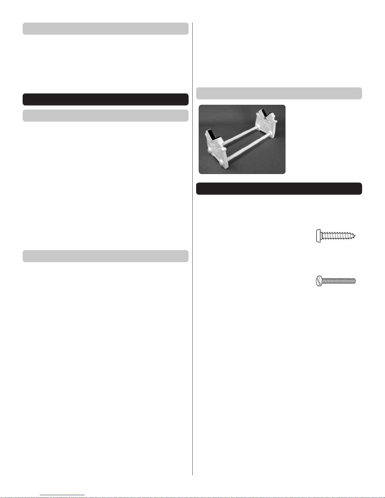
Building Stand
A building stand or cradle
comes in handy during
the build. We use the
Robart Super Stand II
(ROBP1402) for all our
projects in R&D, and it
can be seen in pictures
throughout this manual.
IMPORTANT BUILDING NOTES
● There are three types of screws used in this kit:
Sheet Metal Screws are designated by a number and a
length. For example #6 3/4” [19mm].
This is a number six screw
that is 3/4” [19mm] long.
Machine Screws are designated by a number,
threads per inch, and a length. For example
4-40 3/4” [19mm].
This is a number four screw
that is 3/4” [19mm] long with
forty threads per inch.
● Photos and sketches are placed before the step they refer
to. Frequently you can study photos in following steps to
get another view of the same parts.
● The Avistar Elite ARF is factory-covered with Top Flite®
MonoKote® fi lm. Should repairs ever be required, MonoKote
can be patched with additional MonoKote purchased
separately. MonoKote is packaged in six-foot rolls, but
some hobby shops also sell it by the foot. If only a small
piece of MonoKote is needed for a minor patch, perhaps a
fellow modeler would give you some. MonoKote is applied
with a model airplane covering iron, but in an emergency a
regular iron could be used. A roll of MonoKote includes full
instructions for application. Following are the colors used
on this model and order numbers for six foot rolls.
Orange TOPQ0202 Royal Blue TOPQ0221
Missile Red TOPQ0201 Jet White TOPQ0204
● The stabilizer and wing incidences and engine thrust angles
have been factory-built into this model. However, some
technically-minded modelers may wish to check these
measurements anyway. To view this information visit the
web site at www.hobbico.com and click on “Technical Data.”
4
Page 5
Due to manufacturing tolerances which will have little or no
effect on the way your model will fl y, please expect slight
deviations between your model and the published values.
Illinois and Nevada residents will also be charged sales tax. If
ordering via fax, include a Visa® or MasterCard® number and
expiration date for payment.
KIT INSPECTION
Before starting to build, take an inventory of this kit to make
sure it is complete, and inspect the parts to make sure they
are of acceptable quality. If any parts are missing or are not
of acceptable quality, or if you need assistance with assembly,
contact Product Support. When reporting defective or missing
parts, use the part names exactly as they are written in the
Kit Contents list on this page.
Hobbico Product Support Ph: (217) 398-8970 ext. 5
3002 N Apollo Drive Suite 1 Fax: (217) 398-7721
Champaign, IL 61822
E-mail: airsupport@hobbico.com
ORDERING REPLACEMENT PARTS
Replacement parts for the Hobbico Avistar Elite ARF are
available using the order numbers in the Replacement Parts
List that follows. The fastest, most economical service can be
provided by your hobby dealer or mail-order company. Parts
may also be ordered directly from Hobby Services, but full
retail prices and shipping and handling charges will apply.
Illinois and Nevada residents will also be charged sales tax.
To locate a hobby dealer, visit the Hobbico web site at www.
hobbico.com. Choose “Where to Buy” at the bottom of the menu
on the left side of the page. Follow the instructions provided
on the page to locate a U.S., Canadian or International dealer.
Parts may also be ordered directly from Hobby Services by
calling (217) 398-0007, or via facsimile at (217) 398-7721, but
full retail prices and shipping and handling charges will apply.
Mail parts orders Hobby Services
and payments by 3002 N Apollo Drive, Suite 1
personal check to: Champaign IL 61822
Be certain to specify the order number exactly as listed in the
Replacement Parts List. Payment by credit card or personal
check only; no C.O.D.
If additional assistance is required for any reason contact
Product Support by e-mail at productsupport@hobbico.com,
or by telephone at (217) 398-8970.
REPLACEMENT PARTS LIST
Order No. Description
GPMA4280
GPMA4281
GPMA4282
GPMA4283
GPMA4284
GPMA4285
GPMA4286
GPMA4287
GPMA4288
GPMA4289
HCAA3739
HCAA3740
HCAA3748
GPMQ4522
OSMG0548
Wing Set
Fuselage Set w/o Engine Mount
Tail Surfaces Set
Hatch
Landing Gear Set
Wing Joiner Tube
Electric Motor Mount
Propeller 12x5
Fuel Tank
Decals
Engine Mount
Isosmooth Engine Mount Parts
Tail Mounting Screws (2)
2.5" Red Spinner
.46 AXII ABL Engine
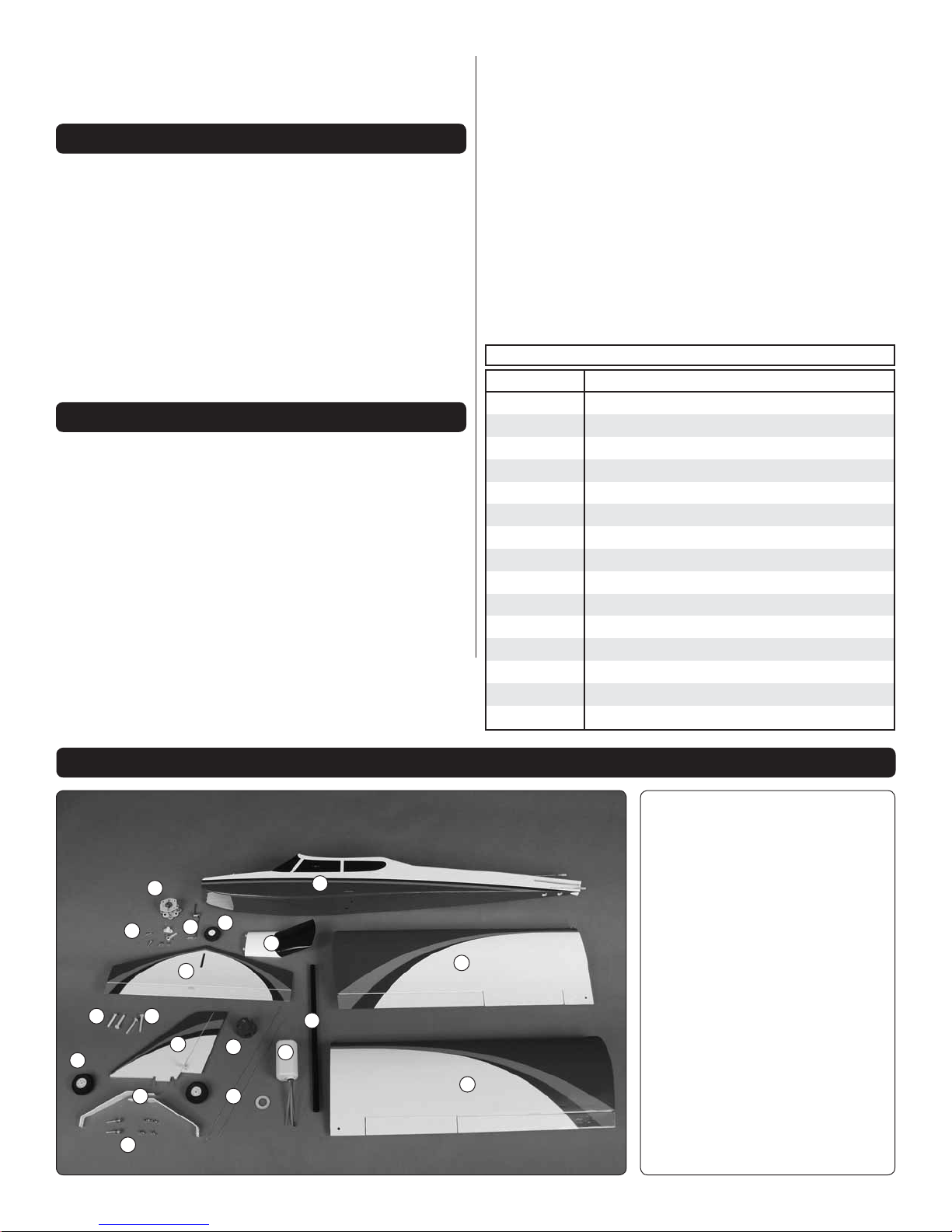
KIT CONTENTS
Kit Contents
1.
Fuselage
2.
Left & Right Wing Panel
3.
13
14
16
11
8
9
10
15
5
3
12
4
17
18
1
2
7
6
2
5
Horizontal Stabilizer
4.
Vertical Fin
5.
Hatch
6.
Fuel Tank
7.
Wing Joiner Tube
8.
Main Wheels
9.
Main Landing Gear
10.
Axle Hardware
11.
Tail Mounting Screws
12.
Wing Bolts
13.
Electric Motor Mount
14.
Nose Wheel
15.
Nose Gear
16.
Nose Gear Hardware
17.
Spinner
18.
Pushrods
Page 6
PREPARATIONS
1. If you have not done so already, remove the major
❏
parts of the kit from the box and inspect for damage. If any
parts are damaged or missing, contact Product Support at
the address or telephone number listed in the “Kit Inspection”
section on page 5.
2. During transit and storage, it is not uncommon for the
❏
MonoKote covering to develop some wrinkles. Although
the covering is applied tight at the factory, humidity and
temperature change may cause the wood structure of the
plane’s components to expand or contract which allows the
covering to relax. Before you begin assembly, we recommend
that any wrinkles in the covering be tightened using a covering
iron with a covering sock on high heat. A covering iron can be
purchased from your hobby retailer and will also be useful if
you ever need to make repairs to the MonoKote covering in
the future. When using the iron, apply pressure over sheeted
areas to thoroughly bond the covering to the wood. Work
gently around open structure (such as the area between the
wing ribs) and allow the heat of the iron to shrink the covering
until it is pulled drum tight.
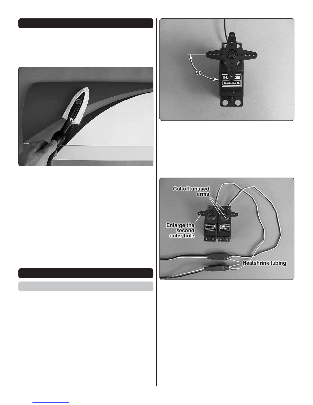
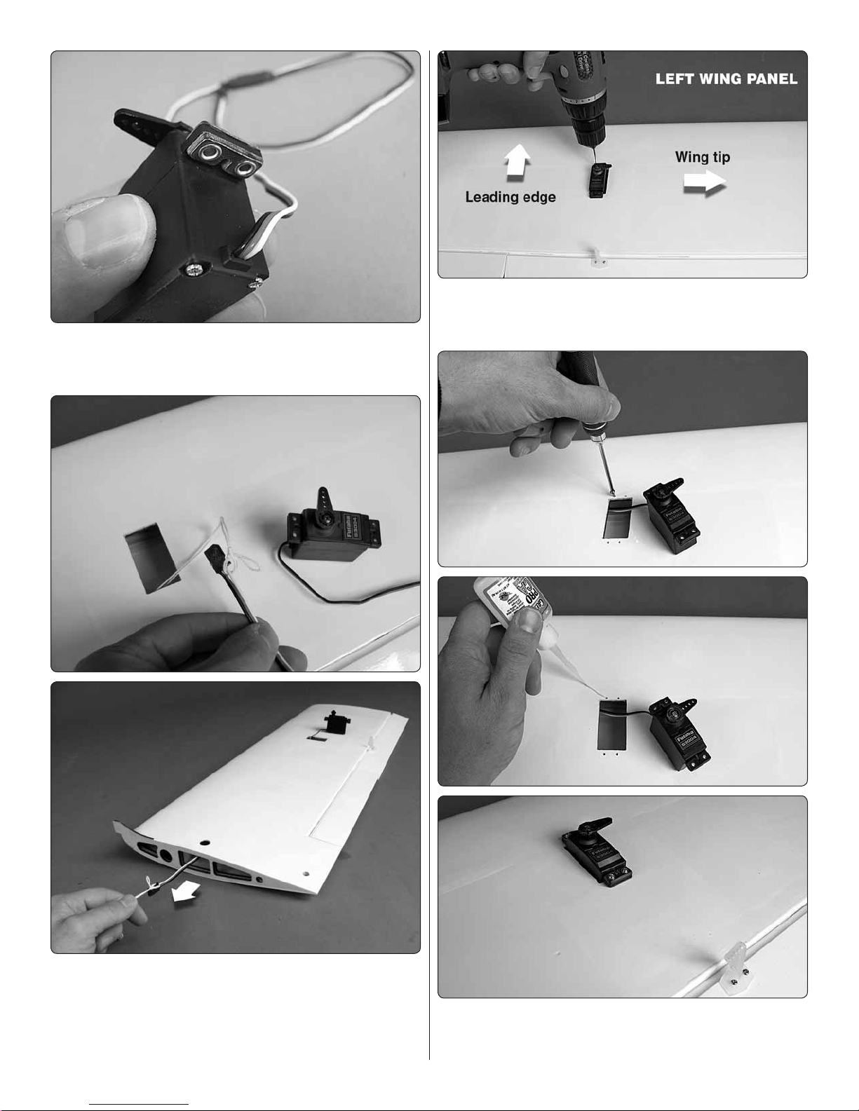
1. Begin by removing the screws that secure the aileron
❏
servo arms and pull the arms off the servos. Connect your
aileron servos to your radio system (see your radio manual for
details about the radio operation) and use the radio system
to center the servos. Reinstall the four-armed servo arms
onto the servos (ensuring the servos remain centered) and
determine the best orientation of the servo arms so that they
are perpendicular to the servo cases as shown.
BUILDING INSTRUCTIONS
Assemble the Wing Panels
After step 2, the photos in this section show the assembly of
the left wing panel. As you work through the steps, be sure
to work on both the left and the right wing panels.
No glue is required to assemble the Avistar Elite. However,
several steps recommend using thin CA glue to harden the
wood surrounding holes for self-tapping screws. Although CA
glue is not absolutely necessary, it will strengthen the wood
and it will be less likely that these screw holes will strip out
over time from fuel exposure and vibration.
2. Using the picture as a guide, cut away three unneeded
❏
arms for each aileron servo, being sure to prepare a left and
a right aileron servo (always be sure to reinstall the servo arm
screws). Enlarge the second outer hole of each remaining
arm with a 5/64" [2mm] drill bit. Attach a 12" [305mm] servo
extension to each aileron servo. Slide a piece of the included
heat shrink tubing over each of the connections. Use a heat
gun or hair dryer to apply heat to the tubing so that it shrinks
tightly around the connectors. This will prevent the connectors
from separating during fl ight.
6
Page 7
3. If you have not already done so, install the rubber
❏
grommets and eyelets (included in your servo hardware bag)
onto the servo mounting tabs.
5. Fit the servos into the servo openings and drill 1/16"
❏
[1.6mm] holes through the mounting tabs on the servo cases
into the rails.
4. Use the strings taped inside the aileron servo openings
❏
to pull the servo leads through the wing.
6. Thread a servo mounting screw (included with the servo)
❏
into each hole and back it out. Apply a drop of thin CA to each
hole to harden the wood surrounding it. When the CA has
7
Page 8
dried, install the servos into the openings using the screws
Pushrod Wire
Servo Arm
1/4" [6.4 mm]
FasLink
supplied with the servos.
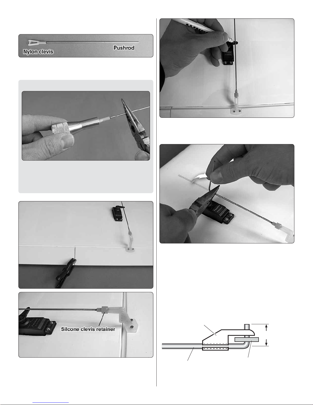
7. Thread a nylon clevis onto two 6-1/4" [159mm] pushrods
❏
20 complete turns.
Builder’s Tip
Installation of the clevises will be much easier using a clevis
installation tool (GPMR8030 or GPMR8035). Nylon clevises
are used on many models so this inexpensive tool will be a
valuable investment for all your future building.
9. With the ailerons and servos still centered, make a mark
❏
on the pushrods where they cross the second outer holes in
the aileron servo arms.
8. Center the positions of the ailerons by using small clamps
❏
or tape to secure them inline with the fl aps. Slide a silicone
clevis retainer onto the base of each clevis. Attach the clevises
on the pushrods to the outer holes in the aileron control horns.
10. Bend each pushrod at a 90 degree angle at the marks
❏
you made.
8
Page 9
11. Cut off the excess pushrod 1/4" [6.4 mm] beyond
❏
the bends. Attach the pushrods to the servo arms using
nylon FasLinks.
13. If you plan to install the optional fl aps, proceed to the
❏
next section. If not, skip the next section and set aside the wing
as it will not be needed again until the fi nal setup of the Avistar.
Optional Flaps
Installing fl aps will require a 5+ channel radio system and two
additional standard servos. The addition of fl aps will allow
the plane to fl y slower for takeoffs and landings. Note that
the fl aps are pinned in place during manufacturing and will
not be able to move until they are cut free at the end of this
assembly section.
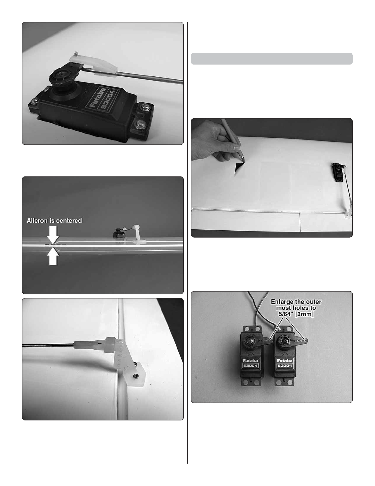
12. Thread the clevises up or down on the pushrods as
❏
necessary to center the ailerons with the servo arms still
perpendicular to the servo cases. When satisfi ed, slide
the silicone clevis retainers to the ends of the clevises to
secure them.
1. Locate the rectangular fl ap servo bays beneath the
❏
covering. If you cannot see them, look at the wing at a shallow
angle or feel around the area shown in the picture and gently
push in on the covering to locate the corners of the bays. Use
a sharp hobby knife to trim the covering along the edges of
the bays.
2. Temporarily connect each fl ap servo to the aileron
❏
channel on your receiver and use the radio system to center
the servos. Install a four-armed servo arm onto each servo
perpendicular to the servo cases and cut away the other three
arms. NOTE: Unlike the aileron servos, the servo arms of the
fl ap servos must both point in the same direction. Enlarge the
outer most holes of each servo arm with a 5/64" [2mm] drill bit.
9
Page 10
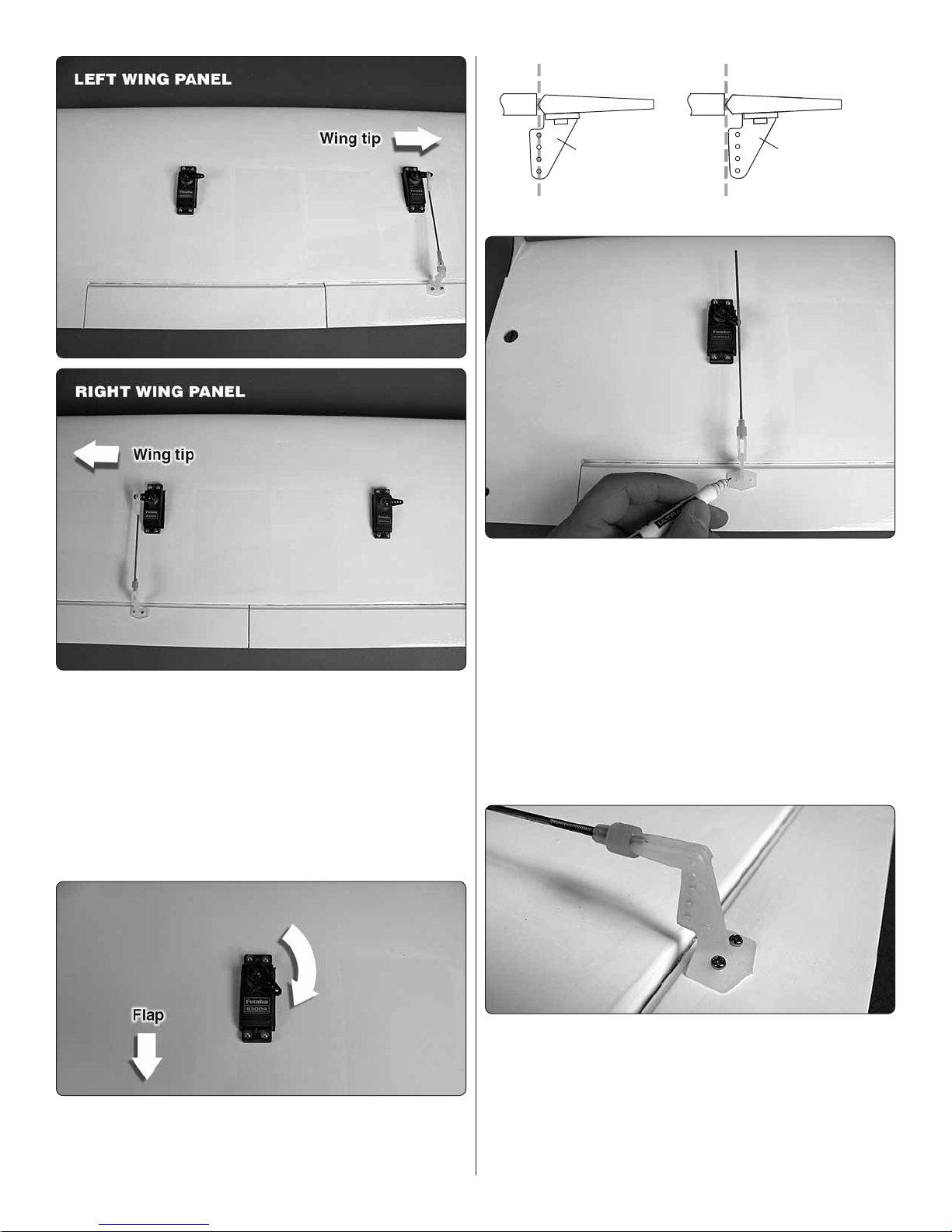
3. Install the rubber grommets and eyelets on the servos.
Hinge Line Hinge Line
CORRECT
INCORRECT
❏
Route the servo leads through the wing ribs and out the root
ribs (the distance through the wing for the fl ap servo leads is
shorter than the ailerons so using string to pull them through
is not necessary). Fit the servos in place and drill the servo
mounting holes using a 1/16" [1.6mm] drill bit. Apply a drop of
thin CA to each hole. Then install the servos using the screws
provided in the servo hardware bag. The servo arm of the left
fl ap servo should point to the wing tip and the servo arm of
the right fl ap servo should point to the wing root.
5. As you did with the aileron pushrods, install a clevis 20
❏
complete turns onto two 6-1/4" [159 mm] pushrods and slide a
silicone clevis retainer onto each clevis. Connect the clevises
to the outer holes of two control horns. Hardwood plates are
installed beneath the covering of the fl aps for mounting the
control horns. The edges of the plates can be seen by viewing
the wing at a shallow angle. Position the control horns over
the hardwood plates with the pushrods parallel to the servo
cases and aligned over the outer holes of the servo arms. The
holes in the control horns should be directly over the hinge
line of the fl aps. When satisfi ed with the position of the control
horns, use a felt-tip pen to mark the location of the control
horn mounting holes onto the fl aps.
4. Now connect each fl ap servo to the fl ap channel on
❏
your radio and use the fl ap dial on your transmitter to rotate
the servo arms toward the fl aps as far as the radio will allow.
6. Drill 1/16" [1.6mm] holes through the hardwood plates
❏
at the marks you made on the fl aps. Take care to only drill
through the plates. Do not drill completely through the
fl aps! The holes only need to be 3/8" [9.5mm] deep. Thread
a #2 x 3/8" [9.5mm] self-tapping screw into each hole and
back it out. Apply a drop or two of thin CA glue to each hole
and allow the glue to harden. Install the control horns onto
the fl aps using four #2 x 3/8" [9.5mm] self-tapping screws.
10
Page 11
7. Use a felt-tip pen to mark the location where the pushrods
❏
cross the outer holes of the fl ap servo arms.
8. Just as you did with the aileron pushrods, bend each
❏
pushrod at a 90 degree angle at the marks you made. Cut off
the excess pushrod 1/4" [6.4 mm] beyond the bends. Attach
the pushrods to the servo arms using nylon FasLinks.
11. You are now completed with the wing assembly. It can
❏
be set aside as it will not be needed again until the fi nal setup
of the Avistar.
Glow Engine Installation
This section only contains information relevant to installing
a glow engine. Skip this section if you plan to install a
brushless motor.
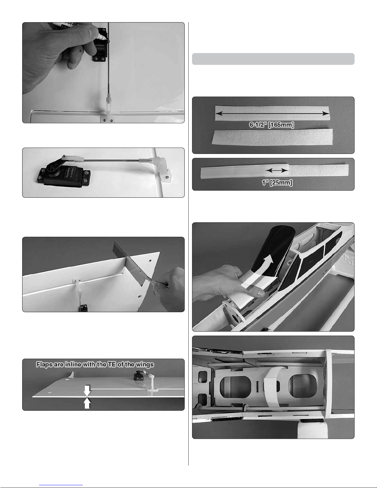
1. Cut 6-1/2" [165mm] from the included hook and loop
❏
strap material. Join the two pieces together to make the fuel
tank strap by overlapping the mating ends 1" [25mm].
9. Wooden pins were installed at the factory that lock the
❏
fl aps in place for those modelers who choose not to have
operational fl aps. Use a razor saw or similar tool to cut through
the pins (the pins can be seen by looking at the inboard ends
of the fl aps). Take care not to cut into the fl aps or wings.
10. Test the operation of the fl aps with your radio system.
❏
Unlike the ailerons, the fl aps will only move in the down
direction. If necessary, thread the clevises up or down on the
pushrods so that the fl aps are inline with the trailing edge of
the wings when the fl ap dial is rotated fully to its stop point.
When satisfi ed, slide the silicone clevis retainers to the end
of the clevises.
2. Lift off the fuselage hatch by sliding it back and up. Route
❏
the strap around the underside of the fuel tank tray. There are
notches on the sides of the tray for the strap.
11
Page 12

3. Cut a piece of 1/4" [6.4mm] foam rubber (not included)
❏
to a size of 2" x 4-3/8" [51mm x 111mm] to line the top of the
fuel tank tray. The purpose of the foam rubber is to dampen
the vibrations from the engine to help prevent the fuel from
foaming.
4. Take a close look at the fuel tank, making note of the
❏
three colored fuel lines. The pink line is the vent line and is
connected to the muffl er to provide pressure to the fuel tank.
The green line is the fi ll line and should remain plugged with
the included fuel line plug. The plug is removed to fi ll and
empty the fuel tank using your fuel pump (not included). The
blue line is the carb line and is connected to the fuel inlet
on your engine (be sure to read and fully understand the
instruction manual of your glow engine). A plywood spacer
disk is included to fi t around the neck of the fuel tank as shown.
Also, before installing the tank, confi rm that the screw in the
stopper is tight (do not apply excessive force to the screw as
it may damage the tank).
5. Fit the fuel tank neck through the hole in the fi rewall and
❏
push it forward as far as it will go. Pull the strap ends tightly
around the top of the fuel tank and connect the mating ends
(be sure the strap sides are aligned in the notches in the tray).
6. Locate the aluminum engine mount, four 6-32 x 3/4"
❏
[19mm] machine screws, four #6 fl at washers and four #6 lock
washers. Slide a lock washer followed by a fl at washer onto
each screw. Apply a couple drops of thread locking compound
onto the threads of each screw. Install the engine mount onto
the fi rewall with the screws. Take care not to cross-thread the
screws. If it feels like a screw is going in with resistance, back
it out, ensure that it is going in straight and try it again. Confi rm
that all four screws are adequately tightened against the mount.
12
Page 13

7. Fit the IsoSmooth rubber boots onto the engine mount
❏
tabs. The boots will reduce the amount of engine vibration that
is transferred to the air frame. Note: the boots are designed
to fi t snugly onto the recommended O.S. engine. If you are
installing another brand engine, you may need to enlarge the
boots to fi t over the mount tabs.
8. Press the IsoSmooth nylon brackets over the boots,
❏
being sure that they are fully seated on the boots.
9. Locate four 4x35mm machine screws, four 4mm fl at
❏
washers, four 4mm lock washers (the 4mm washers are very
similar to the #6 washers and are interchangeable), and four
4mm nuts. Slide a lock washer followed by a fl at washer onto
each screw. Fit the engine onto the engine mount and align
the holes in the nylon brackets with the holes in the mount.
Apply a drop or two of thread locking compound to the end of
each screw. Fit the screws through the holes in the brackets
and through the engine mount. Turn the fuselage on its side
and thread the 4mm nuts onto the screws. Tighten the screws
while allowing the nuts to be become seated in the hexagonal
pockets on the underside of the mount. Confi rm that all four
screws are tight.
10. Install the muffl er onto the engine using the screws
❏
included with your engine. Connect the pink vent line to the
muffl er and the blue carb line to the needle valve. Route the
green fi ll line toward the bottom of the fuselage. The fi ll line
can be cut shorter during fi nal setup to suit your preference.
13
Page 14

11. If your muffl er output is pointing up as shown in the
❏
picture in step 10, remove the muffl er nut at the aft end of
the muffl er and loosen the muffl er screw that passes through
the length of the muffl er. Rotate the muffl er end so the outlet
points down and away from the fuse. Tighten the muffl er screw
and reinstall the nut.
Brushless Motor Installation
with the mount and a drop of thread locking compound on
each screw. Pull of the gold female connectors from the ends
of the motor leads. Since these are already installed on the
ESC, you can set these aside and save them for a future use.
3. Install the prop adapter to the front of the motor with
❏
thread locking compound.
This section only contains information relevant to installing a
brushless motor. Skip this section if you have already installed
a glow engine. NOTE: It is required to disable the BEC circuit
if using the recommended SS-45 ESC. Refer to the ESC
manual for instructions on disabling the BEC.
1. Lift off the fuselage hatch by sliding it back and up.
❏
4. Use a sharp hobby knife to slit the small tabs that hold
❏
the motor wire hole plug in place. Use a hard, pointed tool such
as the end of a pair of nose pliers or a heavy duty screwdriver
to punch out the motor wire hole plug.
2. Install the aluminum ‘X’ mount to the back of the
❏
recommended RimFire .46 motor using the screws included
14
Page 15

5. Locate the plywood brushless motor mount, four 6-32
❏
x 3/4" [19mm] machine screws, four #6 fl at washers and four
#6 lock washers. Slide a lock washer followed by a fl at washer
onto each screw. Apply a couple drops of thread locking
compound onto the threads of each screw. Note that there is
a notch on one side near the back of the mount. The notch
must point down to accommodate the nose gear wire. Install
the motor mount onto the fi rewall with the screws. Take care
not to cross-thread the screws. If it feels like a screw is going
in with resistance, back it out, ensure that it is going in straight
and try it again. Confi rm that all four screws are adequately
tightened against the mount.
7. To improve the adhesion of the double-sided tape and
❏
self-adhesive hook and loop material, mix up a small batch
of epoxy (1/4 oz of 6 or 30 minute epoxy is fi ne) and apply a
thin coating to the inside wall of the fuselage where the ESC
will be installed. With epoxy brush in hand, apply a layer to
the center areas of the battery tray as well. If you do not have
epoxy, you can substitute another product that will bond to
the wood and provide a glossy surface for the tape to stick to
(such as lacquer or CA glue without the use of accelerator).
6. Install the motor onto the motor mount using four 6-32
❏
x 3/4" [19mm] screws and four #6 fl at washers. Be sure to
apply some thread locking compound onto each screw. The
motor should be oriented such that the motor leads are on
the same side as the motor wire hole in the fi rewall.
8. Feed the motor lead wires on the ESC along the side
❏
of the battery tray and out the motor wire hole in the fi rewall.
Connect the three wires on the ESC to the motor wires. At
15
Page 16

this time, the order is unimportant. Later on during setup, if
you discover that the motor rotates in the wrong direction, you
will simply need to swap the position of any two of the three
wires in order to reverse the rotation of the motor.
9. Cut a piece from the included double-sided foam tape
❏
and stick it to the back of the ESC. Secure the ESC over the
area that you applied the epoxy in step 7.
12. Route the strap around the underside of the fuel tank
❏
tray. There are notches on the sides of the tray for the strap.
10. Cut pieces from the included self-adhesive hook and loop
❏
material and stick the hook side as shown on the battery tray.
11. Cut 6" [152mm] from the included hook and loop strap
❏
material. Join the two pieces together to make the battery
strap by overlapping the mating ends 1" [25mm].
13. Apply a length of the soft side from the included self-
❏
adhesive hook and loop material to the underside of your
fl ight battery. Test fi t the battery onto the tray and draw the
strap tightly around it. The exact placement of the battery on
the tray will be determined when you balance the plane in a
later section.
16
Page 17

14. Locate the six oval cool air exit slots on the underside
❏
of the fuselage beneath the covering. There are two slots
aft of the fi rewall and the other four slots are aft of the wing
saddle. Use a sharp hobby knife to carefully trim the covering
from the six slots.
Install the Landing Gear & Tail Section
2. Loosely thread a 6-32 x 1/4" [6.4mm] socket head cap
❏
screw into a 5/32" [4mm] wheel collar. Slide the collar onto
the axle and tighten the screw with a drop of thread locking
compound. Apply a few drops of household oil to the axle.
1. Insert the threaded end of an axle into the hole at the
❏
end of one of the main landing gear legs. Thread a large axle
nut on the axle and use two wrenches to thoroughly tighten
the nut. The fl at spot on the axle should be aligned with the
bottom of the gear leg.
3. Put a 2-1/2" [6.4mm] wheel onto the axle. Follow the
❏
wheel with another 5/32" [4mm] wheel collar and 6-32 x 1/4"
[6.4mm] socket head cap screw. Tighten the screw against
the fl at spot in the axle with some thread locking compound.
Rotate the wheel on the axle and ensure that it rotates freely.
If not, loosen the outside wheel collar, move it slightly away
from the wheel and re-tighten it.
4. Repeat steps 1-3 for the other main landing gear leg.
❏
17
Page 18

5. Fit the main landing gear legs into the slots in the fuselage.
❏
Push them in until the landing gear retaining mechanism
inside the fuselage locks the gear in place. Pull on each leg
to ensure they are secured in the fuselage.
6. Install the nose gear steering block onto the fi rewall
❏
using two 6-32 x 3/4" [19mm] screws, two #6 fl at washers,
and thread locking compound.
7. Fit a 5/32" [4mm]
❏
wheel collar into the nylon
steering arm. Align the
threaded hole in the wheel
collar with the hole in the
side of the arm. Enlarge the
outer hole with a 5/64"
[2mm] drill bit.
8. Loosely thread a
❏
6-32 x 1/4" [6.4mm] socket
head cap screw into a 5/32"
[4mm] wheel collar. Slide
the collar onto the nose
gear axle and tighten the
screw against the inner fl at
spot with a drop of thread
locking compound. Apply
a few drops of household
oil to the axle. Put the 2"
[51mm] nose wheel onto
the axle followed by another
wheel collar and cap screw.
Tighten the cap screw with
thread locking compound against the outer fl at spot on the
axle. Be sure that the wheel rotates freely on the axle.
Note: Should you ever need to remove the landing gear
from the fuselage, insert a screwdriver into the hole under
the fuselage further from the leg you want to remove. Apply
light pressure to the tab inside the hole and pull the landing
gear leg out. Once the tab is moved, the screwdriver must
be removed to allow the leg to come all the way out. Do the
same with the other landing gear leg.
If your landing gear legs spread after a hard landing, remove
the legs from the airplane and bend them back to the correct
position with a vise. Do not try to straighten the legs while
installed in the airplane as that may damage the SnapGear
Landing Gear mechanism.
9. Loosely thread a 6-32 x 1/4" [6.4mm] socket head cap
❏
screw into the nylon steering arm with a drop of thread locking
compound. Slide a wheel collar with a 6-32 x 1/4" socket head
18
Page 19

cap screw loosely threaded in it onto the top of the nose gear
wire up to the coil. Insert the nose gear wire into the steering
block and slide the steering arm onto the nose gear in the
orientation shown. Push the nose gear up as high as it will go
and tighten the screw in the collar that is resting against the
coil. Align the screw in the steering arm with the fl at spot on
the nose gear wire and tighten the screw in it. Ensure that the
nose gear wire turns freely inside the steering block.
10. Slide the horizontal stabilizer into the stab slot in the aft
❏
end of the fuselage. Push it as far forward as it will fi t. Center
the stab in the slot. Look down through the vertical fi n slot and
ensure that the cutout in the horizontal stabilizer is aligned
with the vertical fi n slot.
section is secure. Confi rm that the horizontal stabilizer and
vertical fi n cannot shift in their slots. Take care not to overtighten them as excessive force could damage the wood frame.
Install the Tail Surface Servos & Pushrods
This section shows the installation of the throttle servo and
pushrod for a glow engine. If you installed a brushless motor,
follow only the instructions written for the elevator and rudder
servos and ignore the throttle servo installation.
11. Fit the vertical fi n into the vertical fi n slot. The metal
❏
posts in the fi n should pass through the holes in the bottom
of the fuselage.
12. Locate the two EasyAlign tail bolts. Slide them into the
❏
holes in the underside of the fuselage and onto the threaded
metal posts. The bolts should be tightened snugly so the tail
1. Locate the plywood tail servo tray. Use your radio
❏
system to center your elevator, rudder, and throttle servo (if
you installed a glow engine). Move the throttle stick on your
transmitter to the middle position to center the throttle servo.
As you did with the aileron servos, use the hardware included
with the tail and throttle servos to mount them to the servo
tray. Use thin CA glue to harden the wood surrounding the
screw holes.
19
Page 20

3. Install servo arms onto the elevator and throttle servos
❏
as shown, leaving only two holes in the arms. Enlarge the
outer hole of the elevator servo arm with a 5/64" [2mm] drill
bit. Install a screw-lock pushrod connector into the outer hole
of the throttle servo arm and secure it with a nylon retainer.
Confi rm that you installed the servo arm screws.
4. Thread in and remove a #2 x 3/8" [9.5mm] self-tapping
❏
screw into each of the four tail servo tray mounting holes
that are in the fuselage. Apply a drop of thin CA glue to the
mounting holes and allow the glue to harden. Fit the tail servo
tray in place and screw it down using four #2 x 3/8" [9.5mm]
self-tapping screws and four #2 fl at washers.
2. Test fi t a four-armed servo arm onto the rudder servo to
❏
determine which way it fi ts perpendicular to the servo case.
Cut off two unused arms as shown in the picture, and trim
off the tips of the remaining two arms leaving only two holes
on the left arm and three holes on the right arm. Enlarge the
outer hole of the right arm with a 5/64" [2mm] drill bit. Install a
brass screw-lock pushrod connector into the outer hole of the
left arm and secure it with a nylon retainer. Install the servo
arm onto the rudder servo perpendicular to the servo case.
Be sure to reinstall the servo arm screw.
20
Page 21

6. Remove the pushrod from the fuselage. As you did with
❏
the aileron pushrods, make a 90 degree bend at the mark you
made and cut off the excess pushrod 1/4" [6.4 mm] beyond
the bend. In order to reinstall the pushrod into the fuselage,
you will need to fi rst remove the clevis. Reinsert the pushrod
through the elevator pushrod, thread the clevis back onto
the pushrod 20 turns and reconnect it to the outer hole of
the elevator control horn. Connect the forward end of the
pushrod to the elevator servo arm and secure it with a nylon
FasLink. Make any adjustments to the position of the clevis
on the pushrod to ensure that the elevator is centered with
the servo centered. When satisfi ed, slide the silicone clevis
retainer to the end of the clevis.
5. Thread a nylon clevis with silicone clevis retainer onto a
❏
32-3/4" [832mm] pushrod 20 complete turns. Slide the pushrod
into the elevator pushrod tube and temporarily connect the
clevis to the third outer hole from the base of the elevator
control horn. Use tape or a small clamp to hold the elevator
in the neutral position. Make a mark on the pushrod where it
crosses the hole in the elevator servo arm.
21
Page 22

7. Install the rudder pushrod just as you did the elevator
❏
pushrod. The clevis should be in the outer hole of the rudder
control horn.
9. Insert the pushrod you made in the previous step into
❏
the steering pushrod tube and into the screw-lock pushrod
connector on the rudder servo. Fit the 90 degree bend in the
wire into the outer hole of the steering arm. Loosely thread a
4-40 x 1/4" [6.4mm] socket head cap screw into the screw-
lock connector.
8. Cut off the threaded end from a 17-3/4" [451mm] pushrod.
❏
Make a 90 degree bend 1/4" [6mm] from the end of the pushrod.
Make a very slight bend in the pushrod 3" [76mm] from the
other end of the pushrod. The bend should be made in the
orientation shown in the picture.
10. Center the nose gear so that it points straight ahead.
❏
With the rudder servo still centered, use thread locking
compound, and tighten the socket head cap screw in the
screw-lock connector.
22
Page 23

11. Make the throttle pushrod by threading a nylon clevis
❏
and silicone clevis retainer onto the remaining 17-3/4" [451mm]
pushrod. The pushrod must be bent so that the clevis will
clear the engine mount screw nearest to the throttle arm on
the carburetor. Before bending the wire, insert the pushrod
into the throttle pushrod tube and mark on the wire where the
bends will need to be made. Make any adjustments to the wire
until the clevis can pass over the screw head without contact
when the clevis is attached to the outer hole in the throttle
arm. The pushrod must also be able to move the complete
travel of the carburetor without binding. Note: the muffl er was
removed to better show detail of the throttle pushrod.
12. When you are satisfi ed that the throttle pushrod will
❏
freely move the throttle arm, loosely thread a 4-40 x 1/4"
[6.4 mm] socket head cap screw into the screw-lock connector
on the throttle servo arm. Insert the throttle pushrod through
the screw-lock connector and reconnect it to the throttle arm.
Rotate the carb half open and tighten the socket head screw
in the screw-lock connector.
23
Page 24

to kill the engine. The carburetor will return to its original idle
position (the 3/64" [1.2mm] opening you set when positioning
the pushrod in the screw-lock connector) when the switch is
released. Refer to your radio manual for details on setting up
a throttle cut switch.
Finish the Model
13. Temporarily connect the throttle servo to your radio
❏
system and turn on your transmitter to test the operation of
the throttle. Moving the throttle stick down to the idle position
should close the carburetor leaving approximately a 3/64"
[1.2mm] opening as shown that will keep the engine running
at idle. Moving the throttle stick up to full throttle should open
the carburetor completely. Adjust the position of the pushrod
in the screw-lock connector as necessary so your throttle
matches the pictures.
1. Wrap your receiver battery and receiver with 1/4" [6mm]
❏
foam rubber. Cut the foam around the receiver so the servo
plug sockets remain exposed.
2. Make a strap from the remaining hook and loop material
❏
and use it to secure the receiver battery and receiver to the
radio tray as shown.
14. When you wish to shut off the engine using the
❏
transmitter, you can either use the throttle trim button to close
off the opening in the carburetor barrel completely or you
can set up your transmitter with a “throttle cut” switch (most
computerized radios have a throttle cut feature). The throttle
cut switch is a toggle switch or button on the transmitter that,
when activated, will close off the carb barrel completely in order
24
Page 25

3. If you installed a glow engine a cutout is provided for
❏
the receiver on/off switch on the left side of the fuselage. This
cutout is sized for a Futaba mini switch harness (FUTM4370).
If you are installing a different sized switch, you may need to
modify the opening to accommodate your switch. Install your
switch by removing the two screws that hold the front switch
plate to the switch body. Separate the front plate from the
body and reassemble the switch with it in place in the cutout
in the fuselage.
5. A 2" [51mm] piece of plastic tubing is provided for
❏
positioning the receiver antennas in the orientation described
in your radio’s manual. Cut the piece of tubing into two equal
pieces if your receiver has dual antennas. Glue the tube halves
to the side of the fuselage and insert the antenna ends into
the tubes. The antennas can also be taped in place.
4. Connect your servos (and ESC if used) to the receiver.
❏
Unless you plan to electronically mix your two aileron servos
(and two fl ap servos if applicable) together, you will need a
Y-harness for each pair of servos that you need to join together
into one channel on your receiver. The picture shows a Futaba
dual servo extension (FUTM4130) plugged into the aileron
channel and another plugged into the fl ap channel. As you
did with the aileron servo extensions, use the last piece of 3/8"
[9.5mm] heat shrink tubing to secure the connection between
your receiver battery and switch lead. Take a moment to
bundle the servo wires together and neatly out of the way of
the servos. We used small tie straps (not included) to do this.
6. The charge lead on the switch harness is used for
❏
charging the receiver battery and for checking battery voltage
before fl ight. This lead could be mounted on the side of the
fuselage using a charge lead receptacle. However, since the
25
Page 26

Avistar has a removable hatch, we simply left it inside the
fuselage. It can be easily accessed by removing the hatch.
7. Slide the spinner backplate onto the engine crankshaft
❏
(or brushless motor prop adapter). Depending on the shaft
size of your engine or motor, you may need to enlarge the
hole in the spinner back plate. This can be done with standard
drill bits. However, to ensure the spinner rotates concentrically,
we recommend using a reamer (GPMQ5006 standard prop
reamer, GPMQ5007 metric prop reamer). Balance and install
the prop (ream if necessary) and thoroughly tighten it with the
prop washer and nut (see page 31 about balancing propellers).
9. Fit the servo leads in the wings through the holes in
❏
the underside of the wing panels. Optional fl ap servo leads
are shown.
8. Install the spinner cone onto the backplate using the
❏
included spinner screws. You may need to widen the prop
blade slots in the spinner cone with a hobby knife or rotary
tool if it does not fi t over the propeller.
10. Insert the aluminum wing joiner tube into one of the
❏
wing panels.
11. Slide the wing panels together onto the joiner tube.
❏
26
Page 27

12. Connect the aileron and fl ap servo leads to the dual
❏
servo extensions.
13. Fit the plywood wing root tabs into the slot in the fuselage.
❏
15. You are now completed with the assembly of your Avistar
❏
Elite. Charge your batteries if you have not already done so
and complete the fi nal setup of your model.
Apply the Decals
1. Use scissors or a sharp hobby knife to cut the decals
❏
from the sheet.
2. Be certain the model is clean and free from oily fi ngerprints
❏
and dust. Prepare a dishpan or small bucket with a mixture
of liquid dish soap and warm water—about one teaspoon of
soap per gallon of water. Submerse the decal in the soap and
water and peel off the paper backing. Note: Even though the
decals have a “sticky-back” and are not the water transfer type,
submersing them in soap & water allows accurate positioning
and reduces air bubbles underneath.
3. Position decal on the model where desired. Holding the
❏
decal down, use a paper towel to wipe most of the water away.
4. Use a piece of soft balsa or something similar to squeegee
❏
remaining water from under the decal. Apply the rest of the
decals the same way.
14. Use the included 1/4-20 nylon wing bolts to secure the
❏
wing in place. The tool shown in the picture is a Great Planes
4-In-1 Installation Tool (GPMR8035 not included).
27
Page 28

GET THE MODEL READY TO FLY
Check the Control Directions
1. Turn on the transmitter and receiver and center the trims.
❏
If necessary, remove the servo arms from the servos and
reposition them so they are centered. Reinstall the screws
that hold on the servo arms.
2. With the transmitter and receiver still on, check all the
❏
control surfaces to see if they are centered. If necessary, adjust
the clevises on the pushrods to center the control surfaces.
3. Make certain that the control surfaces and the throttle
❏
respond in the correct direction as shown in the diagram. If any
of the controls respond in the wrong direction, use the servo
reversing in the transmitter to reverse the servos connected to
those controls. Be certain the control surfaces have remained
centered. Adjust if necessary.
28
Page 29

Set the Control Throws
Pushrod Farther Out
Pushrod Farther Out
LESS
THROW
Pushrod Closer In
MORE
THROW
MORE
THROW
Pushrod Closer In
LESS
THROW
To ensure a successful fi rst fl ight, set up your Avistar Elite
according to the control throws specifi ed in this manual. The
throws have been determined through actual fl ight testing
and accurate record-keeping, allowing the model to perform
in the manner in which it was intended. If, after you have
become accustomed to the way the Avistar Elite fl ies, you
would like to change the throws to suit your taste, that is
fi ne. However, too much control throw could make the model
too responsive and diffi cult to control, so remember, “more
is not always better.”
Measure the high rate throws fi rst…
1. Place a ruler fl at on your work surface against the
❏
elevator. Move the elevator up with your transmitter and move
the ruler forward so it will remain contacting the trailing edge.
The distance the elevator moves up from center is the “up”
elevator throw. Measure the down elevator throw the same way.
2. Compare your measurements to the control throw table.
❏
The plane was set up during your build so that the high rate
throws should match or be very close to the measurements in
the table. If they are slightly different, use the ATV (adjustable
travel volume) or EPA (end point adjustment) in your transmitter
to fi ne tune the throws to match. If the throws are signifi cantly
different (more than 1/8" [3mm]), we suggest altering the
positions of the pushrods in the servo arms and control horns
to mechanically change the control throw rather than changing
it digitally. This will ensure that you do not lose “resolution” of
your control throws. If necessary, change the positions of the
pushrods according to the sketches.
3. Measure and set the low rate elevator throws and the
❏
high and low rate throws for the rest of the control surfaces
the same way. Refer to your radio manual for setting up and
using low rates. Flying with low rates will reduce the chance
of over-controlling the plane and is recommended for your fi rst
few fl ights if you are a beginning pilot. As you become more
experienced, low rates may still be preferable for takeoffs
and landings.
NOTE: The throws are measured at the widest part of the
elevator, rudder and ailerons.
These are the recommended control surface throws:
ELEVATORRUDDERAILERONS
LOW RATE
Up & Down
5/16"
[8 mm] 11°
Right & Left
1/2"
[13mm] 13°
HIGH RATE
Up & Down
7/16"
[11mm] 16°
Right & Left
7/8"
[22 mm] 22°
29
Up & Down
3/8"
[10mm] 11°
Up & Down
9/16"
[14mm] 17°
Page 30

If your radio does not have dual rates, we recommend setting
the throws at the low rate settings for your fi rst few fl ights.
We suggest waiting until you are accustomed to the fl ying
characteristics of the Avistar before changing to high rates.
Balance the Model (C.G.)
More than any other factor, the C.G. (center of gravity/
balance point) can have the greatest effect on how a model
fl ies and could determine whether or not your fi rst fl ight will
be successful. If you value your model and wish to enjoy it
for many fl ights, DO NOT OVERLOOK THIS IMPORTANT
PROCEDURE. A model that is not properly balanced may
be unstable and possibly unfl yable.
At this stage the model should be in ready-to-fl y condition
with all of the components in place including the complete
radio system, engine, muffl er, propeller, and spinner (the fl ight
battery should be in place if you installed a brushless motor).
If you’ve built the glow version the fuel tank should be empty.
1. If using a Great Planes C.G. Machine, set the rulers to
❏
3-5/16" [84mm]. If not using a C.G. Machine, use a fi ne-point
felt tip pen to mark lines on the underside of the wing on both
sides of the fuselage 3-5/16" [84mm] back from the leading
edge. Apply narrow (1/16" [2mm]) strips of tape over the lines
so you will be able to feel them when lifting the model with
your fi ngers.
This is where your model should balance for the fi rst
fl ights. Later, you may experiment by shifting the C.G. 3/8”
[9.5mm] forward or 3/8” [9.5mm] back to change the fl ying
characteristics. Moving the C.G. forward will improve the
smoothness and stability, but the model will then be less
aerobatic (which may be fi ne for less-experienced pilots).
Moving the C.G. aft makes the model more maneuverable
and aerobatic for experienced pilots. In any case, start at
the recommended balance point and do not at any time
balance the model outside the specifi ed range.
2. With the wing attached to the fuselage, all parts of the
❏
model installed (ready to fl y) and an empty fuel tank, place the
model on a Great Planes CG Machine, or lift it at the balance
point you marked.
3. If the tail drops, the model is “tail heavy.” If the nose
❏
drops, the model is “nose heavy.” The receiver battery could
be moved forward or aft inside the fuselage to shift the balance
point of the model toward the recommended balancing point.
If the receiver battery cannot be moved, or if additional weight
is still required, nose weight may be easily added by using
“spinner weight” (GPMQ4645 for the 1 oz. [28g] weight, or
GPMQ4646 for the 2 oz. [57g] weight). If spinner weight is
not practical or is not enough, or if tail weight is required,
use Great Planes “stick-on” lead (GPMQ4485). To fi nd out
how much weight is required, place incrementally increasing
amounts of weight on the top of the fuselage over the location
where it would be mounted inside until the model balances.
A good place to add stick-on nose weight is to the fi rewall.
Once you have determined the amount of weight required,
it can be permanently attached. If required, tail weight may
be added by cutting open the bottom of the fuse and gluing
it permanently inside.
Note: If mounting weight where it may be exposed to fuel
or exhaust, do not rely upon the adhesive on the back to
permanently hold it in place. Over time, fuel and exhaust
30
Page 31

residue may soften the adhesive and cause the weight to fall
off. Instead, permanently attach the weight with glue or screws.
4. IMPORTANT: If you found it necessary to add any weight,
❏
recheck the C.G. after the weight has been installed.
Balance the Model Laterally
1. With the wing level, have an assistant help you lift the
❏
model by the engine propeller shaft and the bottom of the
fuse under the TE of the fi n. Do this several times.
2. If one wing always drops when you lift the model, it means
❏
that side is heavy. Balance the airplane by adding weight to the
other wing tip. An airplane that has been laterally balanced
will track better in loops and other maneuvers.
PREFLIGHT
Identify Your Model
No matter if you fl y at an AMA sanctioned R/C club site or if
you fl y somewhere on your own, you should always have your
name, address, telephone number and AMA number on or
inside your model. It is required at all AMA R/C club fl ying sites
and AMA sanctioned fl ying events. Fill out the identifi cation
tag on page 35 and place it on or inside your model.
Balance Propellers
Carefully balance your propeller and spare propellers before
you fl y. An unbalanced prop can be the single most signifi cant
cause of vibration that can damage your model. Not only
will engine mounting screws and bolts loosen, possibly with
disastrous effect, but vibration may also damage your radio
receiver and battery. Vibration can also cause your fuel to
foam, which will, in turn, cause your engine to run hot or quit.
We use a Top Flite Precision Magnetic Prop Balancer
(TOPQ5700) in the workshop and keep a Great Planes
Fingertip Prop Balancer (GPMQ5000) in our fl ight box.
Charge the Batteries
Follow the battery charging instructions that came with your
radio control system to charge the batteries. You should always
charge your transmitter and receiver batteries the night before
you go fl ying, and at other times as recommended by the
radio manufacturer.
CAUTION: Unless the instructions that came with your
radio system state differently, the initial charge on new
transmitter and receiver batteries should be done for 15
hours using the slow-charger that came with the radio
system. This will “condition” the batteries so that the next
charge may be done using the fast-charger of your choice.
If the initial charge is done with a fast-charger the batteries
may not reach their full capacity and you may be fl ying with
batteries that are only partially charged.
Ground Check
If the engine is new, follow the engine manufacturer’s
instructions to break-in the engine. After break-in, confi rm
that the engine idles reliably, transitions smoothly and rapidly
to full power and maintains full power—indefi nitely. After you
run the engine on the model, inspect the model closely to
make sure all screws remained tight, the hinges are secure,
the prop is secure and all pushrods and connectors are secure.
Range Check
Ground check the operational range of your radio before the
fi rst fl ight of the day. Refer to your radio manual for the range
checking procedure of your radio system. During the check,
have an assistant stand by your model and, while you work the
controls, tell you what the control surfaces are doing. Repeat
this test with the engine running at various speeds with an
assistant holding the model, using hand signals to show you
what is happening. If the control surfaces do not respond
correctly, do not fl y! Find and correct the problem fi rst. Look
for loose servo connections or broken wires, corroded wires
on old servo connectors, poor solder joints in your battery
pack or a defective cell.
31
Page 32

ENGINE & ELECTRIC MOTOR
SAFETY PRECAUTIONS
Failure to follow these safety precautions may result in
severe injury to yourself and others.
AMA SAFETY CODE EXCERPTS
Read and abide by the following excerpts from the Academy
of Model Aeronautics Safety Code. For the complete Safety
Code refer to Model Aviation magazine, the AMA web site or
the Code that came with your AMA license.
● Keep all engine fuel in a safe place, away from high heat,
sparks or fl ames, as fuel is very fl ammable. Do not smoke
near the engine or fuel; and remember that engine exhaust
gives off a great deal of deadly carbon monoxide. Therefore
do not run the engine in a closed room or garage.
● Get help from an experienced pilot when learning to operate
engines and electric motors.
● Use safety glasses when starting or running your power
system.
● Do not run the power system in an area of loose gravel or
sand; the propeller may throw such material in your face
or eyes.
● Keep your face and body as well as all spectators away
from the plane of rotation of the propeller as you start and
run the power system.
● Keep these items away from the prop: loose clothing, shirt
sleeves, ties, scarfs, long hair or loose objects such as
pencils or screwdrivers that may fall out of shirt or jacket
pockets into the prop.
● Use a “chicken stick” or electric starter to start a glow
engine. Do not use your fi ngers to fl ip the propeller. Make
certain the glow plug clip or connector is secure so that it
will not pop off or otherwise get into the running propeller.
● Make all engine adjustments from behind the rotating
propeller.
General
1) I will not fl y my model aircraft in sanctioned events, air shows,
or model fl ying demonstrations until it has been proven to be
airworthy by having been previously, successfully fl ight tested.
2) I will not fl y my model aircraft higher than approximately
400 feet within 3 miles of an airport without notifying the
airport operator. I will give right-of-way and avoid fl ying in the
proximity of full-scale aircraft. Where necessary, an observer
shall be utilized to supervise fl ying to avoid having models fl y
in the proximity of full-scale aircraft.
3) Where established, I will abide by the safety rules for the
fl ying site I use, and I will not willfully and deliberately fl y my
models in a careless, reckless and/or dangerous manner.
5) I will not fl y my model unless it is identifi ed with my name
and address or AMA number, on or in the model. Note: This
does not apply to models while being fl own indoors.
7) I will not operate models with pyrotechnics (any device that
explodes, burns, or propels a projectile of any kind).
Radio Control
1) I will have completed a successful radio equipment ground
check before the fi rst fl ight of a new or repaired model.
2) I will not fl y my model aircraft in the presence of spectators
until I become a qualified flier, unless assisted by an
experienced helper.
● The engine or electric motor will get hot! Do not touch it
during or right after operation. Make sure fuel lines are
in good condition so fuel will not leak onto a hot engine,
causing a fi re.
● To stop a glow engine, use your radio system to completely
shut the carburetor barrel or if that method fails to work,
cut off the fuel supply by closing off the fuel line. Do not
use hands, fi ngers or any other body part to try to stop
the engine. Do not throw anything into the propeller of a
running engine.
3) At all fl ying sites a straight or curved line(s) must be
established in front of which all fl ying takes place with the
other side for spectators. Only personnel involved with fl ying
the aircraft are allowed at or in the front of the fl ight line.
Intentional fl ying behind the fl ight line is prohibited.
4) I will operate my model using only radio control frequencies
currently allowed by the Federal Communications Commission.
5) I will not knowingly operate my model within three miles
of any pre-existing fl ying site except in accordance with
the frequency sharing agreement listed [in the complete
AMA Safety Code].
9) Under no circumstances may a pilot or other person touch
a powered model in fl ight; nor should any part of the model
other than the landing gear, intentionally touch the ground,
except while landing.
32
Page 33

CHECK LIST
During the last few moments of preparation your mind may
be elsewhere anticipating the excitement of the fi rst fl ight.
Because of this, you may be more likely to overlook certain
checks and procedures that should be performed before the
model is fl own. To help avoid this, a check list is provided to
make sure these important areas are not overlooked. Many
are covered in the instruction manual, so where appropriate,
refer to the manual for complete instructions. Be sure to
check the items off as they are completed (that’s why it’s
called a check list!).
1. Check the C.G. according to the measurements provided
❏
in the manual.
2. Be certain the battery and receiver are securely mounted
❏
in the fuse. Simply stuffi ng them into place with foam rubber
is not suffi cient.
3. Balance your model laterally as explained in the
❏
instructions.
4. Use thread locking compound to secure critical fasteners
❏
such as the screws that hold the wheel collars to the axles,
engine mount screws, screw-lock pushrod connectors, etc.
5. Add a drop of oil to the axles so the wheels will turn freely.
❏
6. Confi rm that all hinges are securely glued in place.
❏
7. Reinforce holes for wood screws with thin CA where
❏
appropriate (servo mounting screws, etc.).
8. Confi rm that all controls operate in the correct direction
❏
and the throws are set up according to the manual.
9. Make sure there are silicone retainers on all the clevises
❏
and that all servo arms are secured to the servos with the
screws included with your radio.
10. Secure connections between servo wires and servo
❏
extensions using the included heat shrink tubing.
17. Cycle your receiver battery pack (if necessary) and
❏
make sure it is fully charged.
18. If you wish to photograph your model, do so before
❏
your fi rst fl ight.
19. Range check your radio when you get to the fl ying fi eld.
❏
FLYING
Do not attempt to fl y by yourself if you are a beginning
pilot. The Avistar’s docile fl ying characteristics makes learning
to fl y R/C an easier experience, but the help from an instructor
is invaluable. An instructor is going to be able to inspect your
airplane to make sure everything is working correctly and he
will also be able to give you a few tips and comments on how
to improve your fl ying. Also, make sure you fl y at an AMA
sanctioned fl ying fi eld.
CAUTION (THIS APPLIES TO ALL R/C AIRPLANES): If,
while fl ying, you notice an alarming or unusual sound such
as a low-pitched “buzz,” this may indicate control surface
fl utter. Flutter occurs when a control surface (such as an
aileron or elevator) or a fl ying surface (such as a wing or
stab) rapidly vibrates up and down (thus causing the noise).
In extreme cases, if not detected immediately, fl utter can
actually cause the control surface to detach or the fl ying
surface to fail, thus causing loss of control followed by an
impending crash. The best thing to do when fl utter is detected
is to slow the model immediately by reducing power, then
land as soon as safely possible. Identify which surface
fl uttered (so the problem may be resolved) by checking all
the servo grommets for deterioration or signs of vibration.
Make certain all pushrod linkages are secure and free of
play. If it fl uttered once, under similar circumstances it will
probably fl utter again unless the problem is fi xed. Some
things which can cause fl utter are; Excessive hinge gap;
Not mounting control horns solidly; Poor fi t of clevis pin in
horn; Side-play of wire pushrods caused by large bends;
Excessive free play in servo gears; Insecure servo mounting;
and one of the most prevalent causes of fl utter; Flying an
over-powered model at excessive speeds.
11. Make sure any servo extension cords you may have used
❏
do not interfere with other systems (servo arms, pushrods, etc.).
12. Secure the pressure tap (if used) to the muffl er with
❏
high temp RTV silicone, thread locking compound or J.B. Weld.
13. Make sure the fuel lines are connected and are not
❏
kinked.
14. Balance your propeller (and spare propellers).
❏
15. Tighten the propeller nut and spinner.
❏
16. Place your name, address, AMA number and telephone
❏
number on or inside your model.
Taxiing
Before the model is ready for takeoff, it must fi rst be set up
to roll straight down the runway. With the engine running at
a low idle, place the plane on the runway and, if your fl ying
fi eld permits, stand behind the model. Advance the throttle
just enough to allow the model to roll. If the model does not
roll straight down the runway, shut the engine off and adjust
the nose gear pushrod as necessary. Do not use the rudder
trim to correct the nose wheel because this will also affect the
rudder. Note: Crosswinds may affect the direction the model
rolls, so this test should be done in calm conditions, or with
the model facing directly into the wind.
33
Page 34

Takeoff
It is typical when fl ying with an instructor to allow him or her to
have control during take off and landing for at least your fi rst
couple of fl ights. Allow yourself time to become comfortable
with the sticks in the air before attempting a complete fl ight
on your own if you are a beginning pilot.
If possible, take off directly into the wind. If you are experienced,
taking off in a crosswind is permissible (and sometimes
necessary—depending upon the prevailing wind conditions
and runway heading).Taking off into the wind will help the
model roll straight and also reduces ground speed for takeoff.
Taxi the model onto the runway or have an assistant carry
it out and set it down, pointing down the runway into the
wind. When ready, lower the fl aps (if equipped) and gradually
advance the throttle while simultaneously using the left stick
(rudder/nose wheel) to steer the model. Gain as much speed
as the runway and fl ying site will practically allow before gently
applying up elevator lifting the model into the air. Be ready
to make immediate corrections with the ailerons to keep the
wings level, and be smooth on the elevator stick, allowing
the model to establish a gentle climb to a safe altitude before
making the fi rst turn (away from yourself). Do not “yank” back
the elevator stick forcing the plane into too steep of a climb
which could cause the model to quit fl ying and stall.
fi ve to ten feet off the ground. If the model is too far away,
carefully add a small amount of power to fl y the model closer.
If going too fast, smoothly advance the throttle and allow the
model to gain airspeed, then apply elevator to climb out and
go around to make another attempt. When fi nally ready to
touch down, continue to apply up elevator, but not so much
that the airplane will climb. Continue to apply up elevator while
the plane descends until it gently touches down.
After you have landed and shut the engine off, adjust the
pushrods on the ailerons, elevator and rudder as necessary
so the trim levers on the transmitter may be returned to center.
This will not be required on any of the controls that did not
need trim adjustments.
Final Note
One fi nal note about fl ying your model. Have a goal or fl ight
plan in mind for every fl ight. For beginners, your fi rst few
fl ights should be you becoming familiar with the basic controls
of R/C. When the plane is fl ying toward you it is common
for beginner pilots to hesitate or turn the plane in the wrong
direction because the aileron and rudder control will act in
reverse from the pilot’s perspective as it was when fl ying away
from them. Focus on fl ying the model as if you were sitting
in the cockpit. With practice you will learn to do this without
having to think about it.
Flight
Once airborne, maintain a steady climb and make the initial
turn away from the runway. When at a comfortable, safe
altitude, throttle back to slow the model and raise the fl aps
(if equipped), thus giving you time to think and react. The
Avistar Elite should fl y well at half or slightly less than half
throttle. Adjust the trims so the plane fl ies straight and level.
After fl ying around for a while, and while still at a safe altitude
with plenty of fuel (or battery charge), practice slow fl ight and
execute practice landing approaches by reducing the throttle
further to see how the model handles when coming in to land.
Add power to see how the model climbs as well. Continue to
fl y around while learning how the model responds. Mind your
fuel level, but use this fi rst fl ight to become familiar with the
model before landing.
Landing
When ready to land, gently lower the fl aps and pull the throttle
stick fully back while fl ying downwind just before making
the 180-degree turn toward the runway. Allow the nose of
the model to pitch downward to gradually bleed off altitude.
Continue to lose altitude, but maintain airspeed by keeping
the nose down while turning. Apply up elevator to level the
plane when it reaches the end of the runway and is about
As you progress, your fl ight plans should include smooth
takeoffs and landings. Practice executing smooth landings
such that the Avistar approaches the runway in a smooth
and descending path with the correct airspeed and touches
down without bouncing. If possible at your airfi eld, perform
several “touch and go” landings until you are comfortable with
the plane’s landing characteristics.
Regardless of your objective for each fl ight, do not surprise
yourself by impulsively attempting a maneuver and suddenly
fi nding that you’ve run out of time, altitude or airspeed. Every
maneuver should be deliberate, not impulsive. For example, if
you’re going to do a loop, check your altitude, mind the wind
direction (anticipating rudder corrections that will be required
to maintain heading), remember to throttle back at the top, and
make certain you are on the desired rates (high/low rates).
A fl ight plan greatly reduces the chances of crashing your
model just because of poor planning and impulsive moves.
Remember to think.
Have a ball! But always stay in control
and fl y in a safe manner.
GOOD LUCK AND GREAT FLYING!
34
Page 35

This model belongs to:
Name
Address
City, State, Zip
Phone Number
AMA Number
35
Page 36

GPMA1005 Mnl
 Loading...