

Great Plains Industries GPRO PRO25-012PO, GPRO PRO25-012 Series, GPRO PRO25-024PO, GPRO PRO25-024 Series, GPRO PRO25-012PO/XTS Owner's Manual
OWNER'S MANUAL
SAVE THESE INSTRUCTIONS
PRO25-012 PRO25-024
12-Volt DC 24-Volt DC
PRO25-012PO Pump Only PRO25-024PO Pump Only
PRO25-012PO/XTS Pump Only - Extreme
Temperature Series
DO NOT RETURN THIS PRODUCT
TO THE STORE!
Please contact Great Plains Industries before returning any product.
If you are missing parts or experience problems with your installation,
our Customer
Support Department will be happy
800-835-0113 or 316-686-7361
to assist you:
TABLE OF CONTENTS
General Information .................................................... 2
Safety Instructions ...................................................... 2
Installation .................................................................. 3
Operation .................................................................... 4
Maintenance ............................................................... 4
Repair ......................................................................... 4
Troubleshooting .......................................................... 5
Specications ............................................................. 6
Illustrated Parts Drawing ............................................ 7
Parts and Service ....................................................... 8
Warranty .......................................................See Insert
To the owner...
Congratulations on receiving your GPRO® Fuel Transfer
Pump. We are pleased to provide you with a system designed
to give you maximum reliability and efciency.
Your fuel pump is designed, tested, and approved for use with
gasoline blends, diesel fuel blends and kerosene. Please take
all due precautions when handling these ammable liquids.
Your safety is important to us.
Also, to assure the longest possible service life, it is important
that you follow the operation and maintenance procedures
outlined in this manual. We are proud to provide you with a
quality product and dedicated support. Together with your
conscientious use, we are sure that you will obtain years of
safe, dependable service.
02/2017
Victor Lukic, President
Great Plains Industries, Inc.
922106-01 Rev D

GENERAL INFORMATION
The purpose of this manual is to assist you in installing, operating and maintaining your
manual covers models PRO25-012 (12-Volt DC) and
PRO25-024 (24-Volt DC).
GPRO® pump. This
Model Components
PRO25-024PO / PRO25-012PO: Includes pump only.
PRO25-012PO/XTS: Includes pump only and compo-
nents to assemble to unit before use.
NOTE: Sufxes PO and PO/XTS are for ordering purposes
only. Constructions described above are covered as
alternate constructions under the Part No. PRO25
UL Listing.
An automatic bypass valve prevents pressure build
up when the pump is on with the nozzle closed. To
avoid damage, do not run the pump more than 10
minutes with the nozzle closed.
The duty cycle of this pump is 30 minutes ON and 30
minutes OFF. Allow the pump to cool for 30 minutes.
This pump is designed for use only with gasoline (up
to 15% alcohol blends such as E-15), diesel fuel (up to
20% biodiesel blends such as B20) and kerosene. Do
not use this pump for dispensing any uids other than
those for which it was designed. To do so may damage
pump components and will void the warranty.
This pump is designed to operate on a typical DC automotive electrical system. The pump is designed to operate
with the appropriate DC voltage at the motor leads and
the ratings are determined at this voltage. Performance
may vary due to length of power cord, battery condition
or output from the vehicle charging system that will affect
system voltage.
Do not leave the system running with uids. “Dry running”
can damage the pump.
Do not pump the tank completely dry, as contaminants
from the bottom of the tank may enter the pump.
SAFETY INSTRUCTIONS
The following safety alert symbols are used in
this manual. Obey all safety messages that follow
this symbol to avoid possible injury or death.
DANGER
WARNING
DANGER indicates an
imminently hazardous
situation which, if not avoided, will result in death or
serious injury.
WARNING indicates
a potentially hazardous
situation which, if not avoided, could result in death or
serious injury.
CAUTION
There are inherent dangers wherever ammable fuel and
AC electrical sources are in close proximity.
Static electricity as a source of sparking is always a
concern and requires extreme care in the installation and
operation of your entire fuel transfer system.
Additional components such as meters, automatic nozzles
and lters must be listed for use with fuel transfer systems.
The ow of fuel through a hose and nozzle can generate
static electrical charges and dangerous sparking can
result in re or explosion. Hoses and nozzles must be
electrically conductive and bonded to ground.
It is your responsibility to:
• Know and follow applicable national, state and local
safety codes pertaining to installing and operating
electrical equipment for use with ammable liquids.
• Know and follow all safety precautions when handling
petroleum fuels.
• Ensure that all equipment operators have access to
adequate instructions concerning safe operating and
maintenance procedures.
Observe all safety precautions concerning safe handling
of petroleum fuels.
To ensure safe operation, all fuel transfer systems must
be properly grounded. Proper grounding means a continuous metal-to-metal contact from one component to the
next, including tank, bung, pump, meter, lter, hose and
nozzle. Care should be taken to ensure proper grounding
during initial installation and after any service or repair
procedures. For your safety, please take a moment to
review the warnings below.
To prevent physical injury, observe precautions against
re or explosion when dispensing fuel. Do not operate
the system in the presence of any source of ignition
including running or hot engines, lighted cigarettes, or
gas or electric heaters.
Observe precautions against electrical shock when operating the system. Serious or fatal shock can result from
operating electrical equipment in damp or wet locations.
Inspect external pump wiring regularly to make sure it is
correctly attached to the battery. To avoid electrical shock,
use extra care when connecting the pump to power.
Avoid prolonged skin contact with petroleum fuels. Use
protective goggles, gloves and aprons in case of splashing or spills. Change saturated clothing and wash skin
promptly with soap and water.
Observe precautions against electrical shock when
servicing the pump. Always disconnect power before
repairing or servicing. Never apply electrical power to
the system when any of the coverplates are removed.
If using solvent to clean pump components or tank, observe the solvent manufacturer’s recommendations for
safe use and disposal.
CAUTION indicates
a potentially hazardous
situation which, if not avoided, may result in minor or
moderate injury.
2
INSTALLATION
Install Suction Pipe
Your pump is designed to mount directly to a standard
2 in. NPT tank tting. For the suction pipe, a 1 inch
galvanized steel pipe cut to length and threaded on one
end may be used. Suction pipe should extend to within
3 inches of tank bottom. Apply thread tape to the suction
pipe thread and securely tighten the suction pipe to the
pump inlet port.
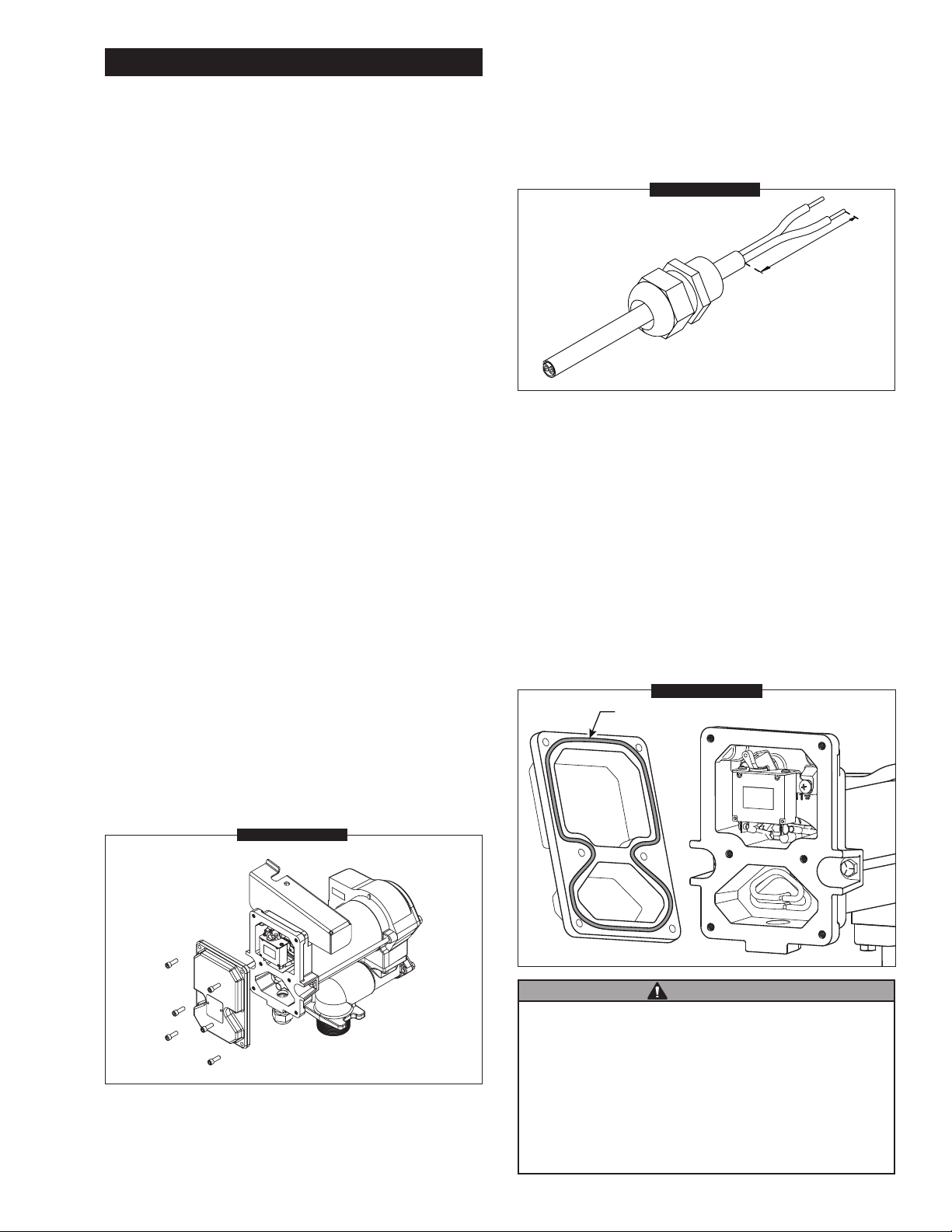
Trim the power cord to the desired length. If your power
cord is not pre-stripped, strip 3 inches of outer insulation
from the power cord end. Then strip 1/2 inch of insulation
from the power cord wires. Slide the strain relief grip onto
the power cord so that the threaded end of the strain relief
grip faces the stripped power wires. (Figure 2)
FIGURE 2
Make sure any check valve or foot valves used are
equipped with proper pressure relief valves.
Install Pump on Tank
• Clean the tank interior of all dirt and foreign material.
• Place the pump with suction pipe installed on the tank
tting and tighten securely. Make sure the pump is not
cross-threaded.
• To prevent pressure build-up and possible fuel leaks
through the nozzle, make sure the tank is vented. A
vent cap rated at 3 psi or less is recommended.
Install Electrical Connections
A grounding connection is provided. It is identied as a green
colored binding head screw in the electrical cavity.
PRO25-012 models must be connected to a 12-volt DC
power source only.
PRO25-024 models must be connected to a 24-volt DC
power source only.
DO NOT attempt to connect these pumps to a 115-volt
AC or 230-volt AC power source.
For installation in unclassied areas, the supplied power
cord, fuse and strain relief grip may be used.
NOTE: These components have not been evaluated as
part of the UL Listed Equipment and are not intended
for use in a Hazardous (Classied) Location.
3 in. Ref.
Insert the power cord through the 3/4 in. NPT connection
on the bottom of the pump.
Using wire nuts, connect the black wire to the black wire
and the white (or red) wire to the white (or red) wire in
the pump’s electrical cavity. Position the wires inside the
electrical cavity and tighten the strain relief grip securely.
Inspect the mating surfaces of the electrical coverplate
and electrical cavity for debris. Clean any debris with
an alcohol wipe. If needed, re-apply a light coating of
Lubriplate® 1242 (or equivalent) white lithium grease
to coverplate perimeter, as shown in Figure 3. Reinstall
electrical coverplate and tighten screws securely to 95105 in•lbs (10.7-11.8 N•m).
Apply grease around
perimeter, as shown
FIGURE 3
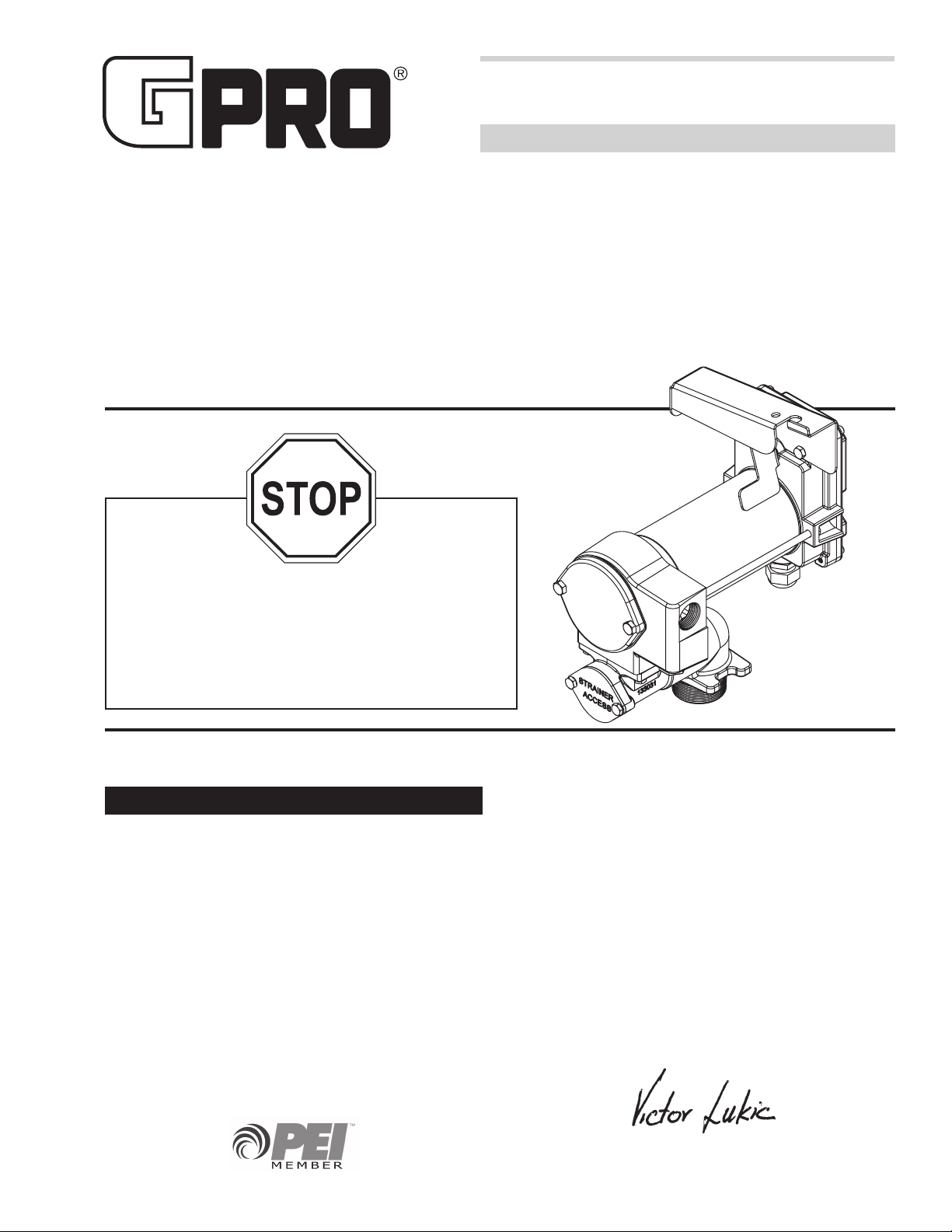
To install the power cord, remove the electrical coverplate.
(Figure 1)
FIGURE 1
WARNING
Carefully route the power cord to the battery, protecting the power
cord from hot surfaces, sharp edges or anything that could damage
the power cord, resulting in a short circuit.
A fuse is provided to protect the power cord and motor. Install fuse
in the white (or red) wire of the power cord as close as possible
to the battery. Connect the red wire of the fuse to the positive
(ungrounded) side of battery. Connect black wire to the negative
(grounded) side of the battery.
Failure to follow these instruction could result in death, serious
injury or loss of equipment due to short circuit, re or explosion.
3
 Loading...