

Page 1
Great Plains Mfg., Inc.
Twin-Row Spacer Bracket
Yield-Pro Planters
Used with:
• Pre-2007 12- and 16-row Yield-Pro Planters
General Information
Installation Instructions 1
These instructions explain how to install the Twin-Row
Spacer Bracket. This feature is now standard on new
products, and is available as an upgrade to existing planters.
These instructions apply to:
198-493A 16 TWIN ROW SPACER KIT
198-494A 12 TWIN ROW SPACER KIT
Installation
1. Inspect your planter for obstructions on the main
toolbar between pairs of twin row units.
Before You Start
Each kit converts one planter.
For each kit, inventory the contents per the “Parts List”
on page 3.
If necessary, move the implement to a dry well-lighted
location suitable for disassembly.
Raise the planter and install lift assist cylinder locks.
Secure the tractor if left connected.
Disconnect any hydraulic and electrical power to the
implement.
If you have ever changed the factory positioning of row
units, measure and mark the correct twin-row centerlines
desired.
Have the following tools at hand:
• Basic hand tools
• Assistance for moving row units
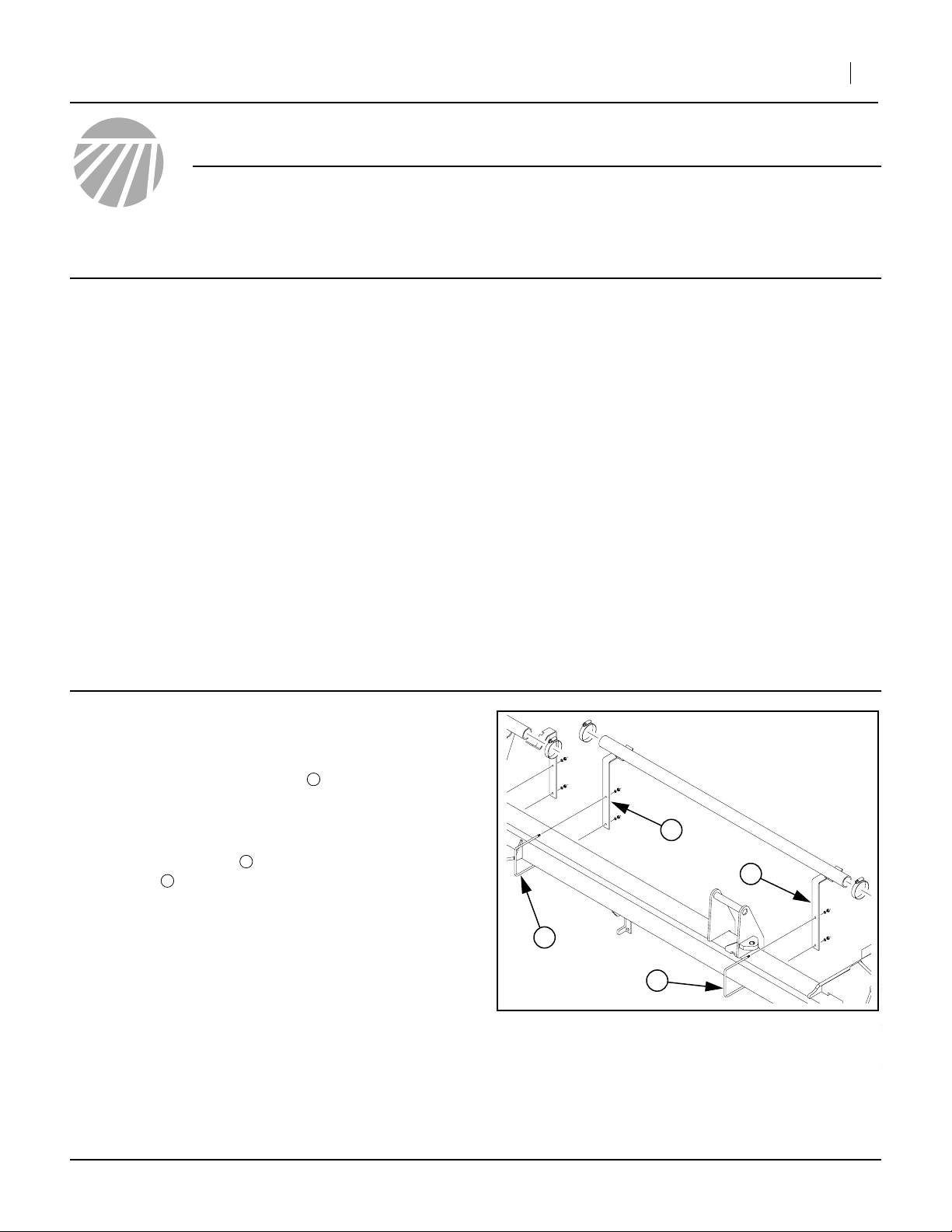
Note: Some planter configurations may have one or
both hose support brackets attached to the
toolbar between twinned row units. If no obstructions are found, skip to step 5.
Refer to Figure 1
2. Remove the U-bolts securing the hose support
brackets to the toolbar.
3. Relocate the hose support bracket mounting points
to outside row unit pairs.
4. Re-install the U-bolts and secure.
1
2
1
1
1
2
2
Figure 1
Hose Support Brackets
©Copyright 2006 Printed 12/21/2006 198-492M
21986
Page 2
2 Twin-Row Spacer Bracket
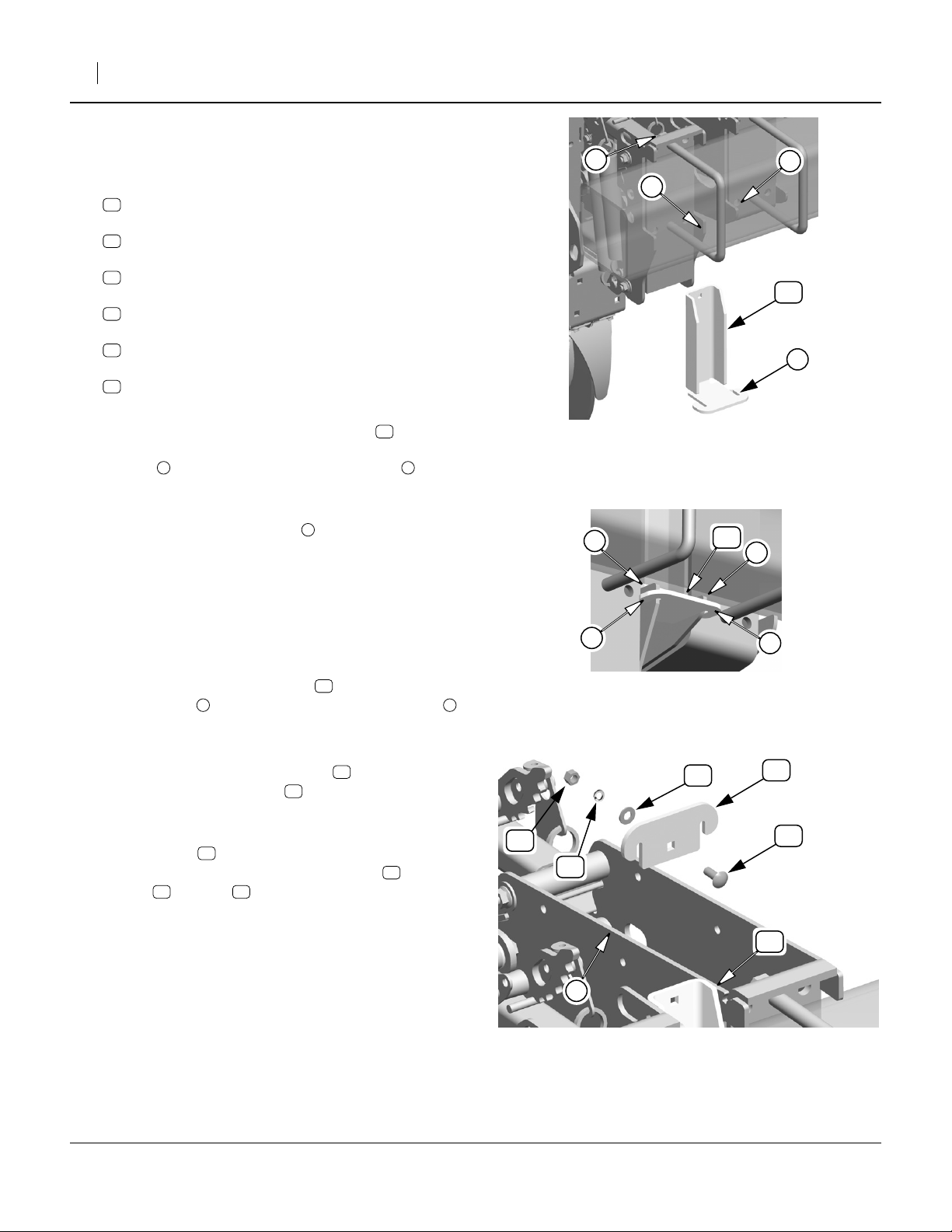
Refer to Figure 2 and Figure 3
Starting at one side of the planter, perform step 5 through
step 11 for each row unit pair.
5. Select one each of:
12
198-334D
TWIN ROW SPACER BRACKET LOWER
13
198-335D
TWIN ROW SPACER BRACKET UPPER
14
802-015C
RHSNB 3/8-16X1 GR5
16
804-012C
WASHER FLAT 3/8 SAE PLT
17
804-013C
WASHER LOCK SPRING 3/8 PLT
15
803-014C
NUT HEX 3/8-16 PLT
6. Make a trial fit of a lower spacer bracket between
the row units of a pair. If it fits snugly, and both retain-
ing ears fit completely over the lower tabs of the
row units, skip to step 9.
7. If it is apparent which of the two row units to adjust,
loosen the nuts on the U-bolt , and slide the row
unit into position. Using the lower spacer bracket to
check fit, tighten the U-bolt.
8. If both row units need to beadjusted, align them so
that the centerline of the row unit pair (and the bolt
hole at the top of the lower spacer bracket) is at the
correct location for the desired row unit spacing.
Tighten both U-bolts.
9. Insert the lower spacer bracket , making sure its
retaining ears fit completely over the lower tabs
of the row units.
Refer to Figure 4
10. Position the upper spacer bracket behind the top
of the lower spacer bracket , so that the ears of the
upper bracket are over the row unit sides, and the
square holes of both brackets align.
11. Insert the bolt through the square holes from
planter front, and secure with flat washer , lock
washer and nut .
1 2
3
12
1 2
12
14
17 15
12
13
16
15
17
3
2
Figure 2
Insert Lower Bracket
2
1
Figure 3
Retaining Ears
16
Great Plains Mfg., Inc.
2
12
1
25388
12
2
1
25389
13
14
12
1
Figure 4
Upper Bracket
198-492M 12/21/2006
25390
Page 3

Great Plains Mfg., Inc.
Figure 5 depicts a completed spacer installation.
Installation Instructions 3
Parts List
198-493A,-494A Twin-Row Spacer Bracket
Your kit includes:
Quantity in Kit...
Callout 198-493A 198-494A Part No. Part Description
11
12
13
14
15
16
17
1 1 198-492M This manual
16 12 198-334D TWIN ROW SPACER BRACKET LOWER
16 12 198-335D TWIN ROW SPACER BRACKET UPPER
16 12 802-015C RHSNB 3/8-16X1 GR5
16 12 803-014C NUT HEX 3/8-16 PLT
16 12 804-012C WASHER FLAT 3/8 SAE PLT
16 12 804-013C WASHER LOCK SPRING 3/8 PLT
Figure 5
Installed Spacer
25391
Great Plains Manufacturing, Inc.
Corporate Office: PO Box 5060
Salina, KS 67402-5060 USA
12/21/2006 198-492M
 Loading...