

Page 1
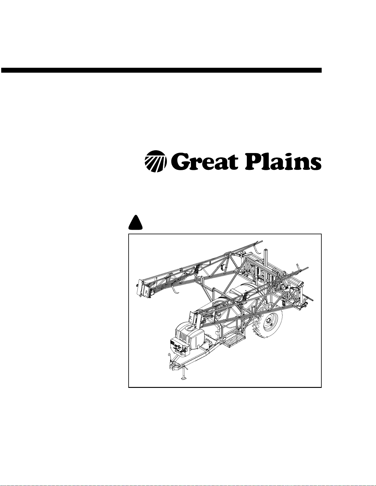
Operator Manual
!
TSF1080, TSF1090, TSF1280 & TSF1290
80- and 90-Foot Front Fold Boom Sprayers
Manufacturing, Inc.
www.greatplainsmfg.com
Read the operator manual entirely. When you see this symbol, the subsequent
instructions and warnings are serious - follow without exception. Your life and
the lives of others depend on it!
27295
Illustrations may show optional equipment not supplied with standard unit.
© Copyright 2012 Printed 05/10/2012 500-641M
Page 2

Page 3

Great Plains Manufacturing, Inc.
Table of Contents
Important Safety Information ....................................1
Safety Reflectors and Decals .......................................8
Introduction ..............................................................17
Document Family .......................................................17
Description of Unit ......................................................17
Intended Usage ......................................................17
Models Covered .....................................................17
Using This Manual......................................................17
Definitions...............................................................17
Owner Assistance ......................................................18
Preparation and Setup .............................................19
Before You Start.........................................................19
Hitching Tractor to Sprayer ........................................19
Hitch Type ..............................................................19
Hitching with Hydraulic Pump.................................20
Hitching with PTO Pump ........................................21
Axle Spacing ..............................................................21
Electrical Connections............................................22
Hydraulic Hookup ...................................................23
Sprayer Control Hydraulic Hookup .....................23
Hydraulic Pump Hookup.....................................23
Tractor / PTO Shaft Hookup.......................................24
Leveling Sprayer ........................................................25
Hitch Height............................................................25
Frame Level Adjustment.........................................26
Leveling Boom........................................................26
Locking System Setup................................................27
Hydraulic Pump Setup................................................27
Ace Pump Flow Limiter (Option).............................28
Flow Limiter Installation ......................................28
Setting Pump Rate .................................................28
Electrical Installation...................................................28
Lights......................................................................28
Raven SCS 450......................................................29
Raven Setup.......................................................29
Hydraulic Valve Control..........................................30
Foam Marker Control (Option)................................30
Raven Auto-Boom (Option) ....................................31
Spraying Setup...........................................................31
Hydraulic Pump Setup............................................31
PTO Pump Setup ...................................................31
Manual Throttle Valve ............................................ 32
Sprayer Calibration .................................................... 33
Speed Calibration................................................... 33
Rate Calibration .....................................................34
Operations ................................................................ 36
General Notes For Field Operation............................ 36
Operating Checklist................................................ 37
Using Hand Wash Tank ............................................. 37
Transporting............................................................... 38
Plumbing Overview .................................................... 38
Filling Tanks............................................................... 42
Filling Hand Wash Tank ......................................... 42
Filling the Flush Tank ............................................. 43
Filling the Main Tank .............................................. 43
Inspect Main Tank Quad Jets ............................ 43
Adding Water to Main Tank................................ 44
Main Fill Using Sprayer’s Pump ......................... 44
Main Fill Using Supply Pump .............................45
Adding Chemicals ...................................................... 46
Inducting Chemicals (Option)................................. 47
Agitation ..................................................................... 48
Foam Marker Tank Fill ........................................... 48
Boom Operations ....................................................... 49
2007+ Sprayer Hydraulics...................................... 49
2006- Sprayer Hydraulics....................................... 49
Elevator Raising/Lowering .....................................49
Boom Height ...................................................... 49
Boom Unfolding...................................................... 50
Boom Fold.............................................................. 50
Boom Tilt ................................................................ 50
Autoboom Operation (Option) ................................ 50
60-Foot Spraying.................................................... 51
Conversion to 60-Foot, from Folded .................. 51
Conversion to 60-Foot, from Unfolded ............... 51
Re-conversion to Full Width ............................... 51
Operating Pump......................................................... 52
Unloading Materials ................................................... 52
Tank and Boom Flush................................................ 53
Parking....................................................................... 54
Unhitching with Hydraulic Pump ............................55
Unhitching with PTO Pump .................................... 55
© Copyright 2005, 2006, 2007, 2008, 2009, 2010, 2011, 2012. All rights Reserved.
Great Plains Manufacturing, Inc. provides this publication “as is” without warranty of any kind, either expressed or implied. While every precaution has been
taken in the preparation of this manual, Great Plains Manufacturing, Inc. assumes no responsibility for errors or omissions. Neither is any liability assumed for
damages resulting from the use of the information contained herein. Great Plains Manufacturing, Inc. reserves the right to revise and improve its products as
it sees fit. This publication describes the state of this product at the time of its publication, and may not reflect the product in the future.
05/10/2012 500-641M
Trademarks of Great Plains Manufacturing, Inc. include: Singulator Plus, Swath Command, Terra-Tine.
Registered Trademarks of Great Plains Manufacturing, Inc. include:
Air-Pro, Clear-Shot, Discovator, Great Plains, Land Pride, MeterCone, Nutri-Pro, Seed-Lok, Solid Stand,
Terra-Guard, Turbo-Chisel, Turbo-Chopper, Turbo Max, Turbo-Till, Ultra-Till, Verti-Till, Whirlfilter, Yield-Pro.
Brand and Product Names that appear and are owned by others are trademarks of their respective owners.
Printed in the United States of America
Page 4

TSF1080, TSF1090, TSF1280 & TSF1290 Great Plains Manufacturing, Inc.
Table of Contents
Storage ...................................................................... 56
Adjustments ............................................................. 57
General Field Adjustments......................................... 57
Boom Height ..........................................................57
Nozzle Pressure..................................................... 57
Axle Wheel Spacing Adjustment................................ 58
Break Away Spring .................................................... 59
Troubleshooting....................................................... 60
Maintenance and Lubrication ................................. 62
Maintenance .............................................................. 62
Sprayer/Boom Maintenance .................................. 62
Equipment Cleanup ............................................... 62
General Information ...............................................62
Filter Maintenance ................................................. 63
Clean-out the solution Whirlfilter®...................... 63
Clean Out Tank Fill Filter ................................... 63
Shear Bolt ..............................................................64
Pump Maintenance & Repair ................................. 65
Ace Pumps............................................................. 66
Ace Pump Disassembly ..................................... 66
Ace Pump Assembly .......................................... 67
Ace Belt Drive Pump Seal Replacement............ 68
Elevator Slide......................................................... 69
Quad-Jet Agitators ................................................. 69
Tank Entry.............................................................. 70
Lubrication ................................................................. 71
Options ..................................................................... 74
Autoboom .................................................................. 74
Axles and Wheels...................................................... 74
Calibration Accessories ............................................. 75
Chemical Inductor...................................................... 75
High Volume Foam Marker........................................ 75
Gauge Protector ........................................................ 76
Hitches (Hydraulic Pump Only) ................................. 76
Open Center Hydraulic Kit......................................... 76
Pumps ....................................................................... 77
Ace Hydraulic Pump .............................................. 77
Ace Flow Limiter ................................................ 77
Ace PTO Pumps .................................................... 77
Speed Sensors .......................................................... 78
Radar Speed Sensor ............................................. 78
Raven Wheel Speed Sensor ................................. 78
Y-Cable.................................................................. 78
Appendix .................................................................. 79
Specifications and Capacities.................................... 79
Tire Inflation Chart ..................................................... 79
Torque Values ........................................................... 80
Hydraulic and Plumbing Diagrams ............................ 81
Boom Hydraulics.................................................... 81
Standard Closed Center Pin Assignments ............ 82
Manifold-Boom Assignments ................................. 83
Raven G1 Autoboom Hydraulics ........................... 84
Index ......................................................................... 87
© Copyright 2005, 2006, 2007, 2008, 2009, 2010, 2011, 2012. All rights Reserved.
Great Plains Manufacturing, Inc. provides this publication “as is” without warranty of any kind, either expressed or implied. While every precaution has been
taken in the preparation of this manual, Great Plains Manufacturing, Inc. assumes no responsibility for errors or omissions. Neither is any liability assumed for
damages resulting from the use of the information contained herein. Great Plains Manufacturing, Inc. reserves the right to revise and improve its products as
it sees fit. This publication describes the state of this product at the time of its publication, and may not reflect the product in the future.
500-641M 05/10/2012
Trademarks of Great Plains Manufacturing, Inc. include: Singulator Plus, Swath Command, Terra-Tine.
Registered Trademarks of Great Plains Manufacturing, Inc. include:
Air-Pro, Clear-Shot, Discovator, Great Plains, Land Pride, MeterCone, Nutri-Pro, Seed-Lok, Solid Stand,
Terra-Guard, Turbo-Chisel, Turbo-Chopper, Turbo Max, Turbo-Till, Ultra-Till, Verti-Till, Whirlfilter, Yield-Pro.
Brand and Product Names that appear and are owned by others are trademarks of their respective owners.
Printed in the United States of America
Page 5
Great Plains Manufacturing, Inc. Important Safety Information 1
Important Safety Information
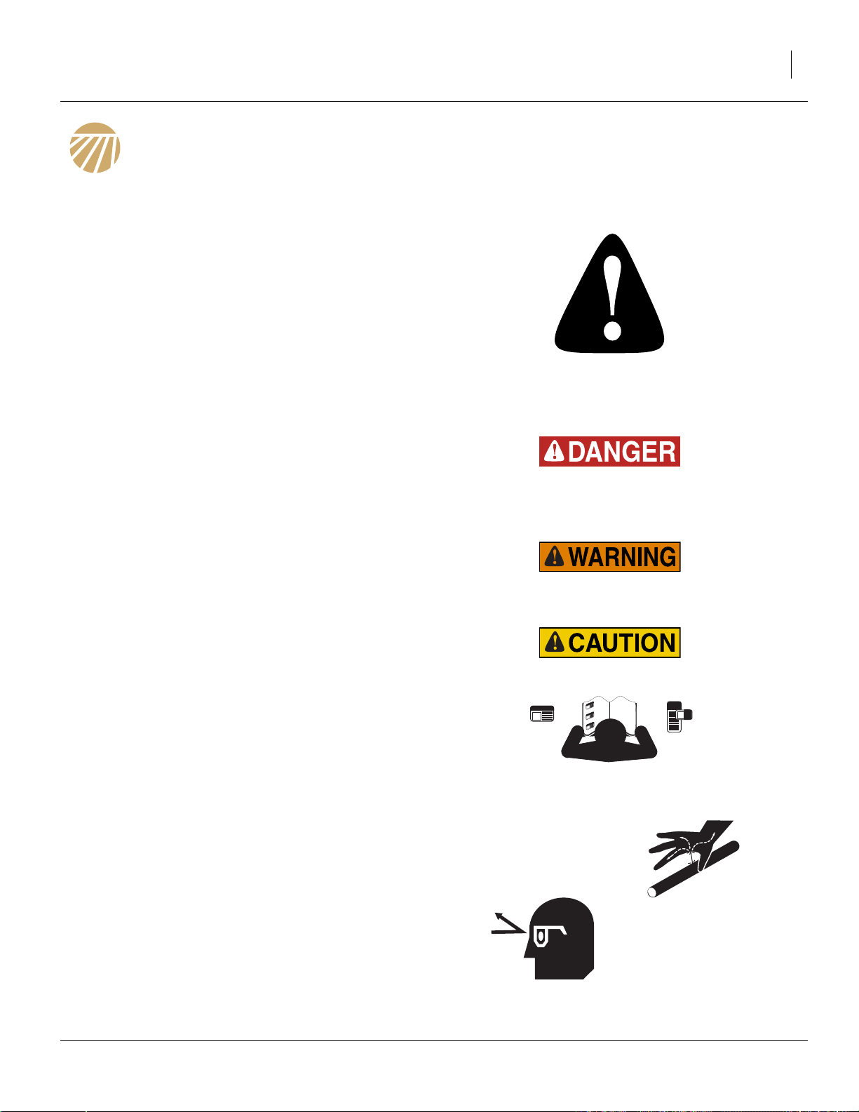
Look for Safety Symbol
The SAFETY ALERT SYMBOL indicates there is a
potential hazard to personal safety involved and extra
safety precaution must be taken. When you see this
symbol, be alert and carefully read the message that follows it. In addition to design and configuration of equipment, hazard control and accident prevention are
dependent upon the awareness, concern, prudence and
proper training of personnel involved in the operation,
transport, maintenance and storage of equipment.
Be Aware of Signal Words
Signal words designate a degree or level of hazard seriousness.
DANGER indicates an imminently hazardous situation
which, if not avoided, will result in death or serious injury.
This signal word is limited to the most extreme situations,
typically for machine components that, for functional purposes, cannot be guarded.
WARNING indicates a potentially hazardous situation
which, if not avoided, could result in death or serious
injury, and includes hazards that are exposed when
guards are removed. It may also be used to alert against
unsafe practices.
CAUTION indicates a potentially hazardous situation
which, if not avoided, may result in minor or moderate
injury. It may also be used to alert against unsafe practices.
Be Familiar with Safety Decals
▲ Read and unerstand “Safety Reflectors and Decals” start-
ing on page 8, thoroughly.
▲ Read all instructions noted on the decals.
Avoid High Pressure Fluids
▲ Escaping fluid under pressure can penetrate the skin, caus-
ing serious injury. If hydraulic fluid penetrates the skin
under pressure, immediate medical attention is required.
See a physician familiar with this type of injury
▲ Avoid the hazard by relieving pressure before disconnecting
hydraulic lines.
▲ Use a piece of paper or cardboard, NOT BODY PARTS, to
check for suspected leaks.
▲ Wear protective gloves and safety glasses or goggles when
working with hydraulic systems.
05/10/2012 500-641M
Page 6

2 TSF1080, TSF1090, TSF1280 & TSF1290 Great Plains Manufacturing, Inc.
Wear Protective Equipment
Great Plains advises all users of chemical pesticides or
herbicides to use the following personal safety equipment.
▲ Waterproof, wide-brimmed hat
▲ Waterproof apron.
▲ Face shield, goggles or full face respirator.
▲ Goggles with side shields or a full face respirator is
required if handling or applying dusts, wettable powders, or
granules or if being exposed to spray mist.
▲ Cartridge-type respirator approved for pesticide vapors
unless label specifies another type of respirator.
▲ Waterproof, unlined gloves. Neoprene gloves are recom-
mended.
▲ Cloth coveralls/outer clothing changed daily; waterproof
items if there is a chance of becoming wet with spray
▲ Waterproof boots or foot coverings
▲ Do not wear contaminated clothing. Wash protective cloth-
ing and equipment with soap and water after each use. Personal clothing must be laundered separately from
household articles.
▲ Clothing contaminated with certain pesticides must be
destroyed according to state and local regulations. Read
chemical label for specific instructions.
▲ Wear clothing and equipment appropriate for the job. Avoid
loose-fitting clothing.
▲ Prolonged exposure to loud noise can cause hearing
impairment or loss. Wear suitable hearing protection such
as earmuffs or earplugs.
▲ Avoid wearing entertainment headphones while operating
machinery. Operating equipment safely requires the full
attention of the operator.
500-641M 05/10/2012
Page 7

Great Plains Manufacturing, Inc. Important Safety Information 3
Handle Chemicals Properly
▲ Read and follow chemical manufacturer’s instructions.
▲ Wear protective clothing.
▲ Handle all chemicals with care.
▲ Agricultural chemicals can be dangerous. Improper use can
seriously injure persons, animals, plants, soil and property.
▲ Inhaling smoke from any type of chemical fire is a serious
health hazard.
▲ Store or dispose of unused chemicals as specified by the
chemical manufacturer.
▲ Before adding chemical to the tank, make sure tank is at
least half full. Do not pour concentrate into an empty tank.
▲ Never leave fill hose attached to the sprayer after filling
tank. Chemicals in tank can siphon out of tank and contaminate freshwater source.
▲ Always keep hand-wash tank filled with clean water and
have soap available in case of an emergency. Immediately
and thoroughly flush any area of the body that is contaminated by chemicals.
▲ Do not touch sprayer components with mouth or lips.
▲ If chemical is swallowed, carefully follow the chemical
manufacturer’s recommendations and consult with a doctor.
▲ If persons are exposed to a chemical in a way that could
affect their health, consult a doctor immediately with the
chemical label or container in hand. Any delay could cause
serious illness or death.
▲ Dispose of empty chemical containers properly. By law
rinsing of the used chemical container must be repeated
three times. Puncture the container to prevent future use. An
alternative is to jet-rinse or pressure rinse the container.
▲ Wash hands and face before eating after working with
chemicals. Shower as soon as spraying is completed for the
day.
▲ Spray only with acceptable wind conditions. Wind speed
must be below 5 mph. Make sure wind drift of chemicals
will not affect any surrounding land, people or animals.
▲ Never wash out the sprayer tank within 100 feet (30m) of
any freshwater source or in a car wash.
▲ Rinse out the tank. Spray rinse water on last field sprayed.
05/10/2012 500-641M
Page 8
4 TSF1080, TSF1090, TSF1280 & TSF1290 Great Plains Manufacturing, Inc.
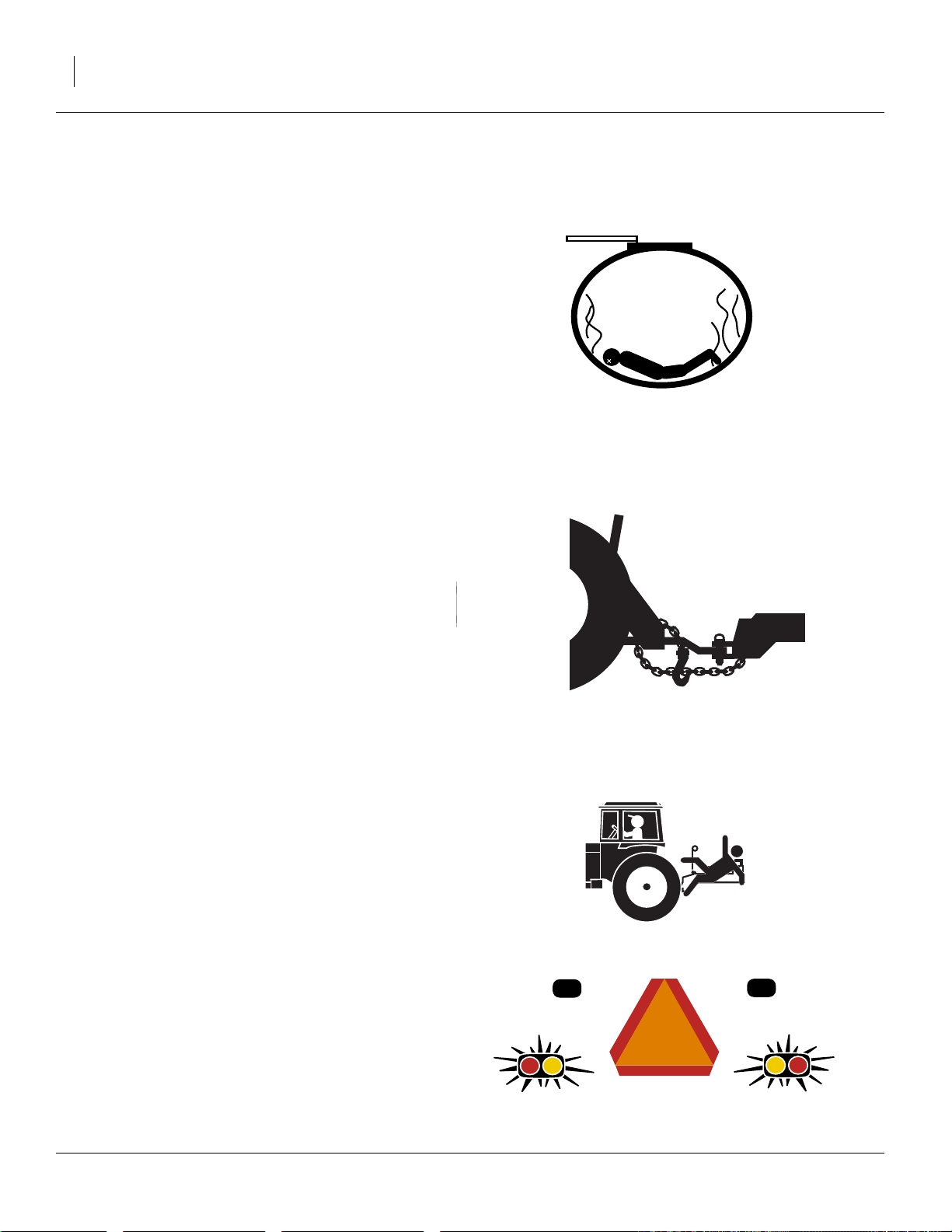
Confined Space
Once used for hazardous fertilizers, or seeds with hazardous treatments, your tank may become a
“permit-required confined space” under applicable statutes, regulations, insurance rules or business policy.
▲ When hazardous fumes are present, you can be quickly
overcome even with the tank lid open.
▲ Do not enter a tank for material loading, material unload-
ing, tank cleaning or valve maintenance.
▲ Clean tank by power washing from outside the tank top.
▲ Perform valve maintenance by removing meters from bot-
tom of empty tank.
▲ If obstruction removal or repair requires tank entry, have
the work performed by a team trained in confined space
procedures. See “Tank Entry” on page 70.
Use A Safety Chain
▲ Use a safety chain to help control drawn machinery should
it separate from tractor drawbar.
▲ Use a chain with a strength rating equal to or greater than
the gross weight of towed machinery.
▲ Attach chain to tractor drawbar support or other specified
anchor location. Allow only enough slack in chain to permit
turning.
▲ Replace chain if any links or end fittings are broken,
stretched or damaged.
▲ Do not use safety chain for towing.
Keep Riders Off Machinery
▲ Riders obstruct the operator’s view. Riders could be struck
by foreign objects or thrown from the machine.
▲ Never allow children to operate equipment.
▲ Keep all bystanders away from machine during operation.
Use Safety Lights and Devices
▲ Slow-moving tractors and towed implements can create a
hazard when driven on public roads. They are difficult to
see, especially at night.
▲ Use flashing warning lights and turn signals whenever driv-
ing on public roads.
▲ Use tractor lights and lights provided with implement.
500-641M 05/10/2012
Page 9
Great Plains Manufacturing, Inc. Important Safety Information 5
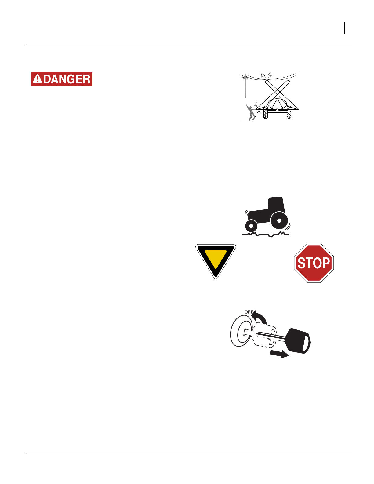
Check for Overhead Lines
Sprayer booms contacting overhead electrical lines can introduce lethal voltage levels on sprayer and tractor frames. A
person touching almost any metal part can complete the circuit to ground, resulting in serious injury or death. At higher
voltages, electrocution can occur without direct contact.
▲ Avoid overhead lines during sprayer operations.
Transport Machinery Safely
▲ Maximum transport speed for implement is 20 mph (32
kph). Some rough terrains require a slower speed. Sudden
braking can cause a towed load to swerve and upset.
▲ Do not exceed 20 mph (32 kph). Never travel at a speed
which does not allow adequate control of steering and stopping. Reduce speed if towed load is not equipped with
brakes.
▲ Comply with state and local laws.
▲ Do not tow an implement that, when fully loaded, weighs
more than 1.5 times the weight of towing vehicle.
▲ Carry reflectors or flags to mark Front Fold Boom Sprayer
in case of breakdown on the road.
▲ Keep clear of overhead power lines and other obstructions
when transporting. Refer to transport dimensions under
“Specifications and Capacities” on page 79.
▲ Do not fold or unfold the Front Fold Boom Sprayer while
the tractor is moving.
Shutdown and Storage
▲ Fold Front Fold Boom Sprayer, put tractor in park, turn off
engine, and remove the key.
▲ Secure Front Fold Boom Sprayer using blocks and supports
provided.
▲ Detach and store Front Fold Boom Sprayer in an area
where children normally do not play.
05/10/2012 500-641M
Page 10
6 TSF1080, TSF1090, TSF1280 & TSF1290 Great Plains Manufacturing, Inc.
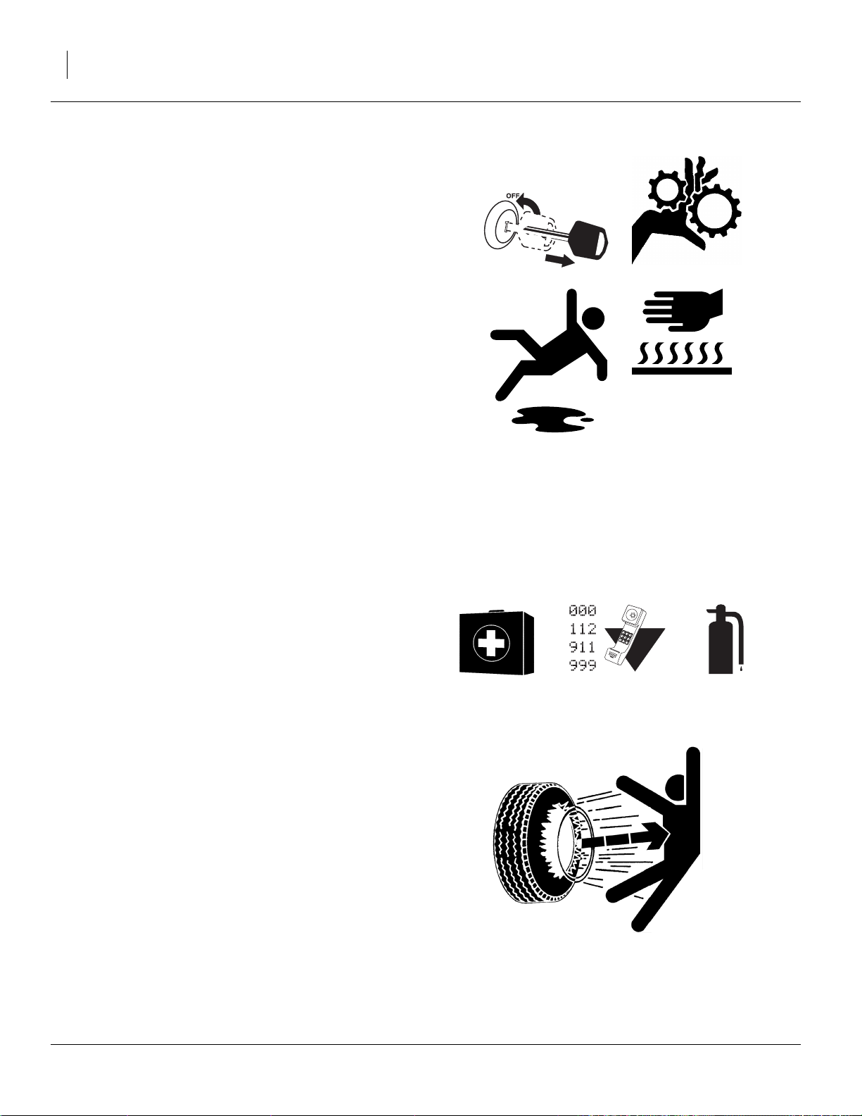
Practice Safe Maintenance
▲ Understand procedure before doing work. Use proper tools
and equipment. Refer to this manual for additional information.
▲ Work in a clean, dry area.
▲ Fold the Front Fold Boom Sprayer, put tractor in park, turn
off engine, and remove key before performing maintenance.
▲ Make sure all moving parts have stopped and all system
pressure is relieved.
▲ Allow Front Fold Boom Sprayer to cool completely.
▲ Disconnect battery ground cable (-) before servicing or
adjusting electrical systems or before welding on Front Fold
Boom Sprayer.
▲ Inspect all parts. Make sure parts are in good condition and
installed properly.
▲ Remove buildup of grease, oil or debris.
▲ Remove all tools and unused parts from Front Fold Boom
Sprayer before operation.
Prepare for Emergencies
▲ Be prepared if a fire starts.
▲ Keep a first aid kit and fire extinguisher handy.
▲ Keep emergency numbers for doctor, ambulance, hospital
and fire department near phone.
Tire Safety
▲ Tire changing can be dangerous and should be performed
by trained personnel using correct tools and equipment.
▲ When inflating tires, use a clip-on chuck and extension hose
long enough for you to stand to one side–not in front of or
over tire assembly. Use a safety cage if available.
▲ When removing and installing wheels, use wheel-handling
equipment adequate for weight involved.
500-641M 05/10/2012
Page 11

Great Plains Manufacturing, Inc. Important Safety Information 7
Safety At All Times
▲ Thoroughly read and understand the instructions in this
manual before operation. Read all instructions noted on the
safety decals.
▲ Be familiar with all Front Fold Boom Sprayer functions.
▲ Operate machinery from the driver’s seat only.
▲ Do not leave Front Fold Boom Sprayer unattended with
tractor engine running.
▲ Do not dismount a moving tractor. Dismounting a moving
tractor could cause serious injury or death.
▲ Do not stand between the tractor and Front Fold Boom
Sprayer during hitching.
▲ Keep hands, feet and clothing away from power-driven
parts.
▲ Wear snug-fitting clothing to avoid entanglement with mov-
ing parts.
▲ Watch out for wires, trees, etc., when folding and raising
Front Fold Boom Sprayer. Make sure all persons are clear
of working area.
▲ Do not turn tractor too tightly, causing Front Fold Boom
Sprayer to ride up on wheels. This could cause personal
injury or equipment damage.
▲ Use only water without pesticides added to calibrate the
sprayer. Do not exceed the calibrated sprayer speed and
pressure when operating.
▲ When using a PTO pump, be sure that PTO shield is in
place on the tractor, PTO coupler bolts are torqued to the
correct specification, and torque bar is properly chained to
tractor drawbar.
▲ Spray with the boom in the unfolded position only.
▲ The boom has many pinch points during field operation and
folding. Keep all bystanders away.
▲ Never use tank for potable water.
05/10/2012 500-641M
Page 12
8 TSF1080, TSF1090, TSF1280 & TSF1290 Great Plains Manufacturing, Inc.
Safety Reflectors and Decals
Your sprayer comes equipped with all safety reflectors
and decals in place. They were designed to help you
safely operate your sprayer.
▲ Read and follow decal directions.
▲ Keep all safety decals clean and legible.
▲ Replace all damaged or missing decals. Order new decals
from your Great Plains dealer. Refer to this section for
proper decal placement.
▲ When ordering new parts or components, also request cor-
responding safety decals.
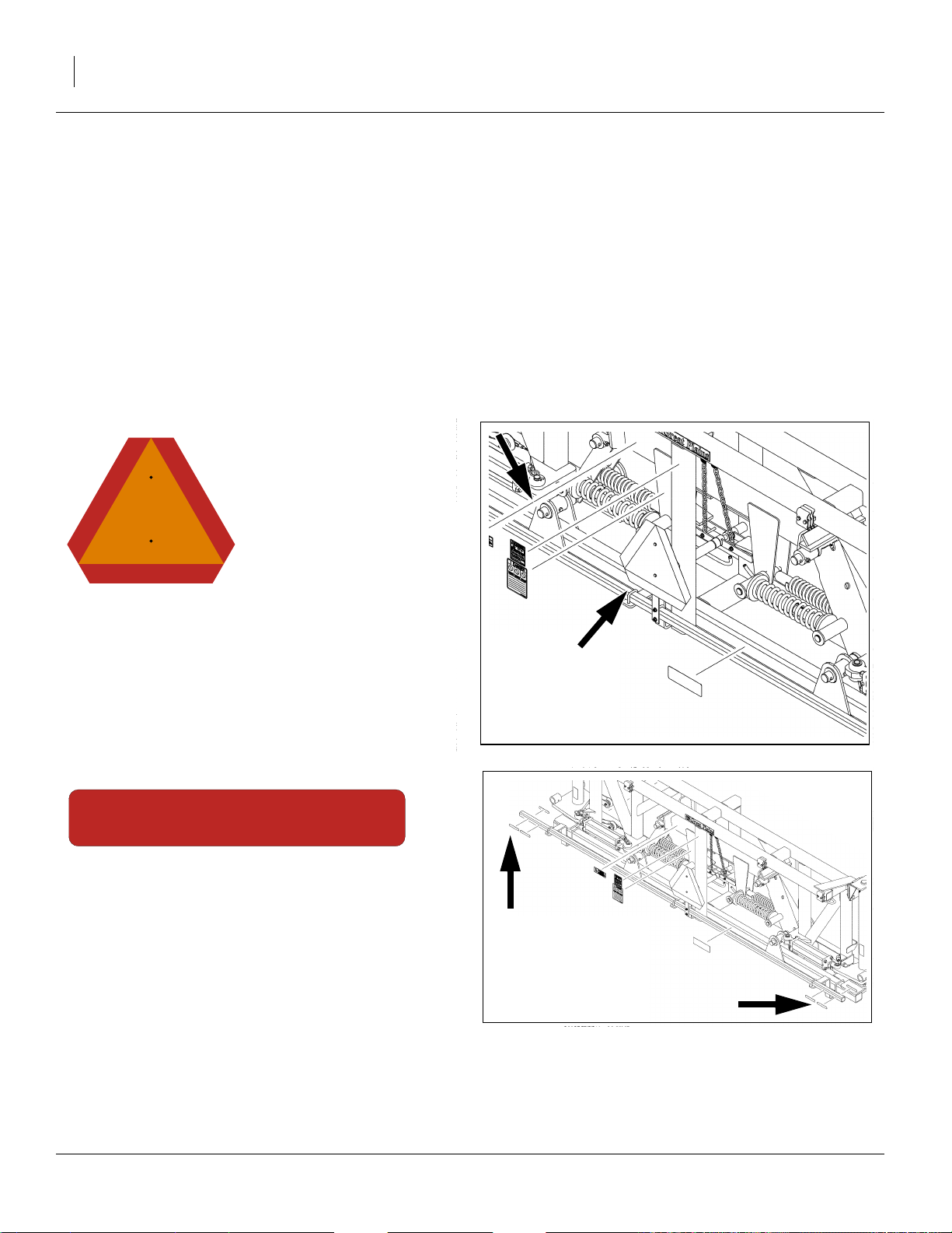
Slow Moving Vehicle Reflector
To install new decals:
1. Clean the area on which the decal is to be placed.
2. Peel backing from decal. Press firmly on surface,
being careful not to cause air bubbles under decal.
818-055C
center section of boom, facing to rear;
1 total
Red Reflectors
818-266C
center section of boom, outside ends,
rear face of lower tube;
2 total
20441
20441
500-641M 05/10/2012
Page 13
Great Plains Manufacturing, Inc. Important Safety Information 9
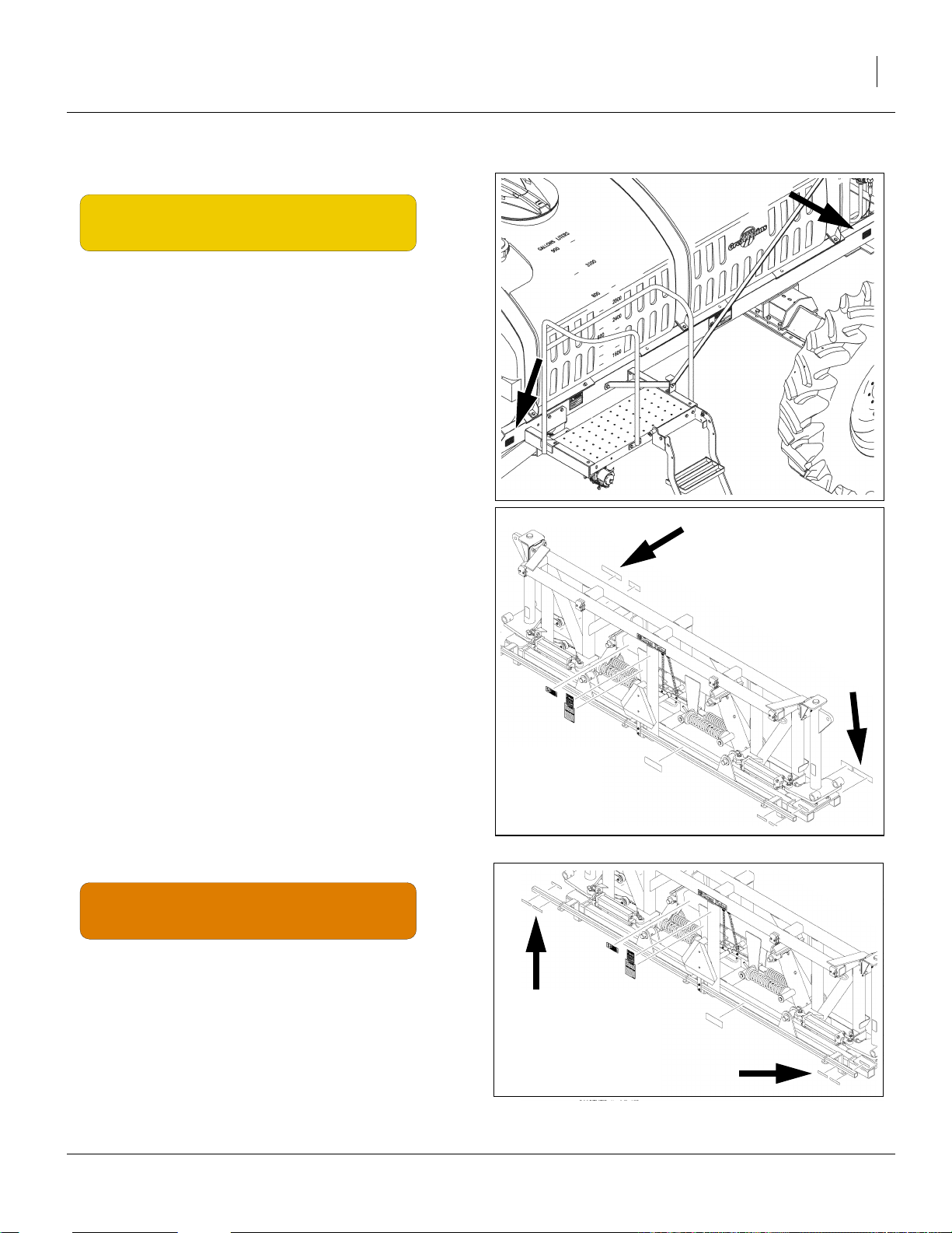
Amber Reflectors
818-265C
main frame, outside faces, front & rear corners;
center section of boom, front face of forward tube, outside ends:
6 total
20377
20441
Daytime Reflectors
818-267C
center section of boom, rear face of lower tube, just
inboard of Red reflectors;
2 total
20441
05/10/2012 500-641M
Page 14
10 TSF1080, TSF1090, TSF1280 & TSF1290 Great Plains Manufacturing, Inc.
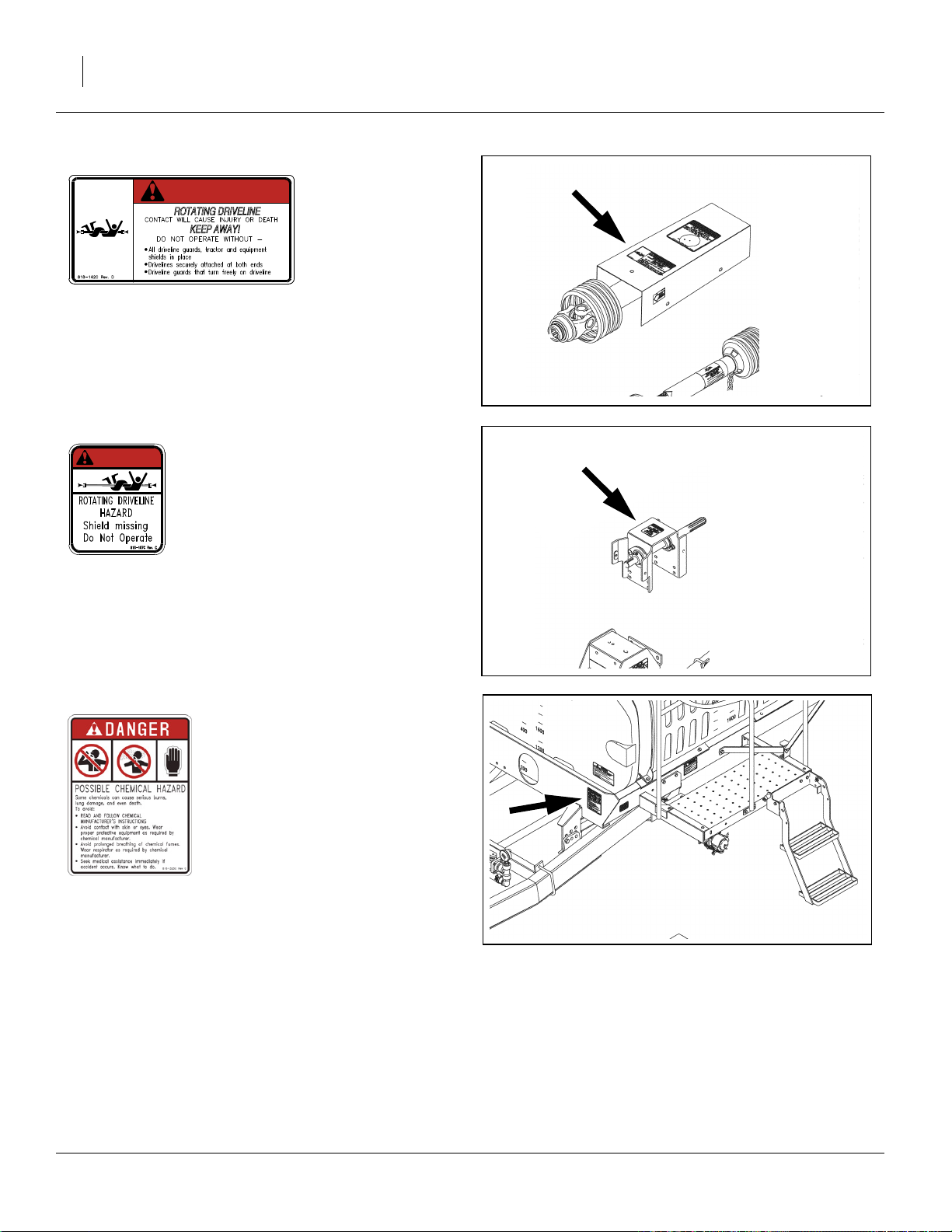
Danger: Rotating Driveline (PTO only)
DANGER
818-142C
top of PTO shaft guard;
1 total
20377
Danger: Rotating Driveline (PTO only)
DANGER
818-187C
top of PTO bearing mount guard;
1 total
Danger: Agricultural Chemicals
818-323C
forward face of mainframe, left side;
1 total
20377
500-641M 05/10/2012
Page 15
Great Plains Manufacturing, Inc. Important Safety Information 11
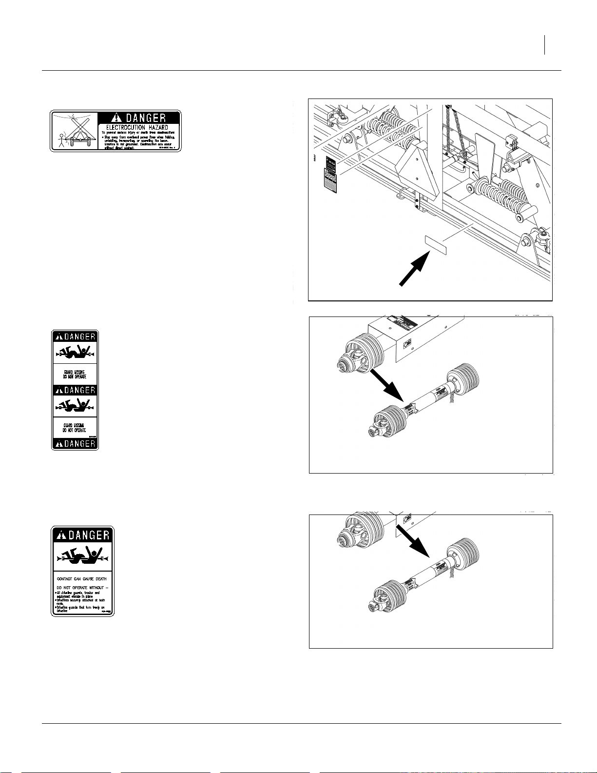
Danger: Electrocution Hazard
818-367C
center section of boom, rear face of lower rear tube;
1 total
20441
Danger: Guard Missing (PTO only)
818-540C
20377
forward end of PTO driveline
(visible only when in an unsafe condition);
1 total
Danger: Guard Missing (PTO only)
ROTATING DRIVELINE
KEEP AWAY!
818-552C
aft end of PTO driveline
(visible only when in an unsafe condition);
1 total
05/10/2012 500-641M
20377
Page 16
12 TSF1080, TSF1090, TSF1280 & TSF1290 Great Plains Manufacturing, Inc.
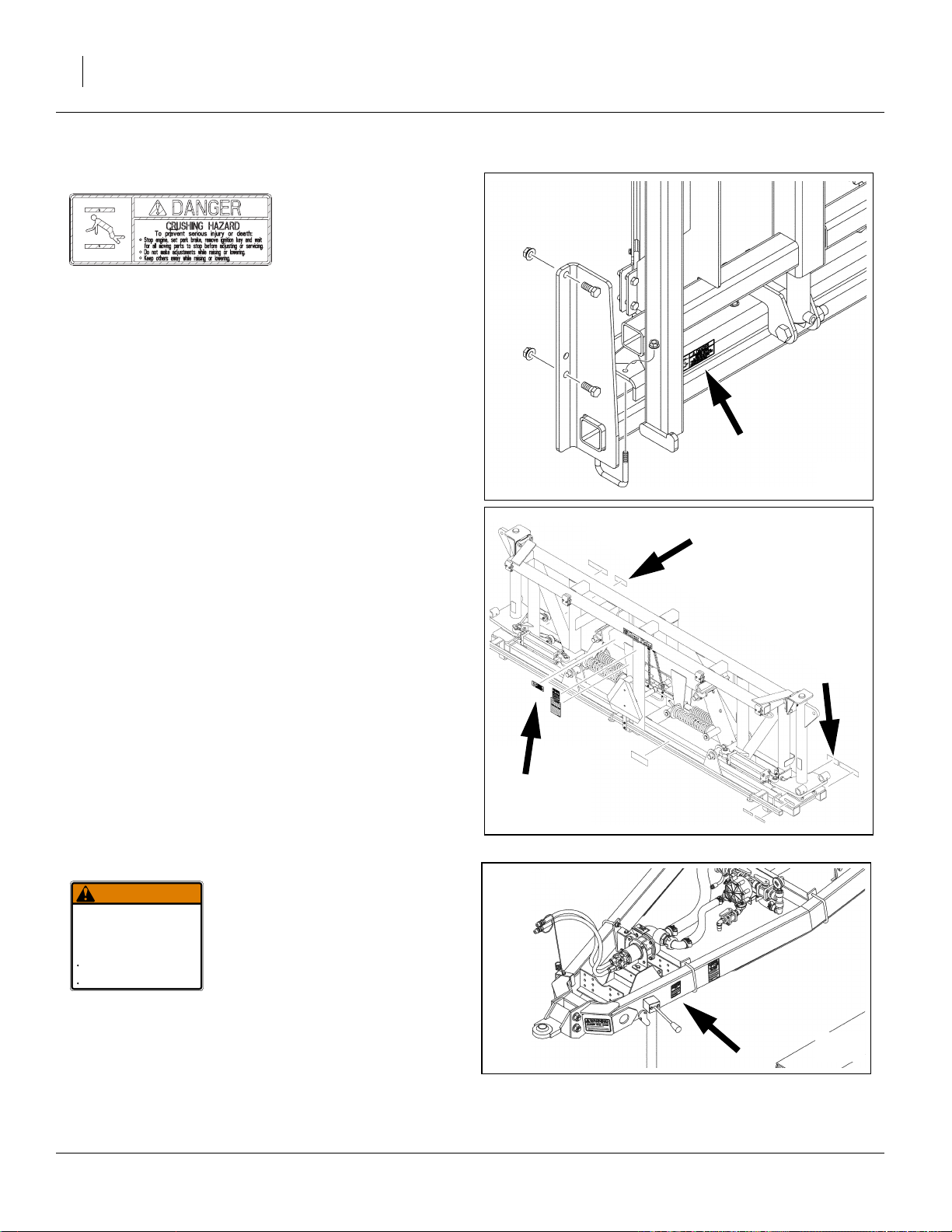
Danger: Crushing Hazard
818-864C
base of elevator(1),
boom center section, rear face of fixed mount(1),
boom center section, inboard of amber reflectors(2);
4 total
20238
20441
Warning: Negative Tongue Weight
WARNING
NEGATIVE TONGUE WEIGHT
HAZARD
Negative tongue weight can cause immediate
elevation of tongue when unhitching implement
To prevent serious injury or death:
Always be certain implement is hitched securely
to tractor drawbar before raising.
Lower implement BEFORE unhitching.
818-019C
left side of tongue;
1 total
500-641M 05/10/2012
818019C Rev D
20377
Page 17
Great Plains Manufacturing, Inc. Important Safety Information 13
Warning: Excessive Speed
WARNING
EXCESSIVE SPEED HAZARD
To Prevent Serious Injury or Death:
Do Not exceed 20 mph maximum transport
speed. Loss of vehicle control and/or machine
can result.
818-188C
front left side of hitch;
1 total
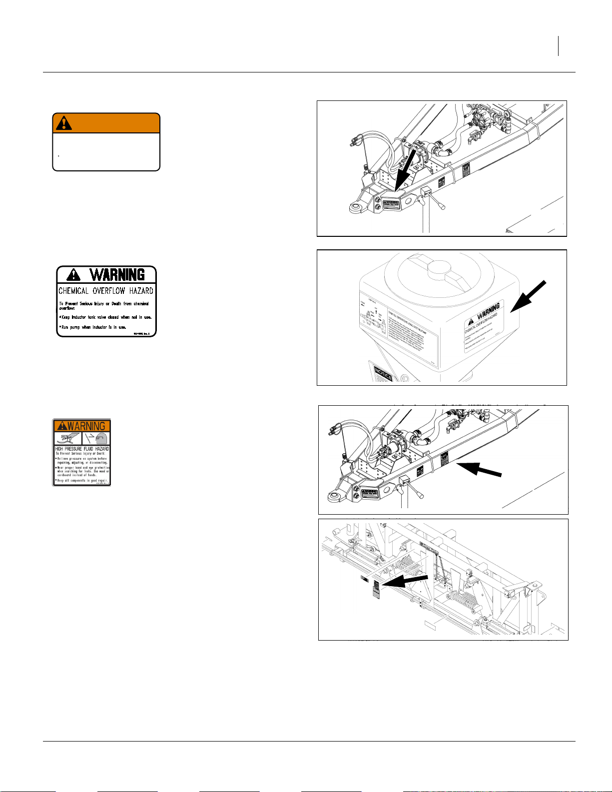
Warning: Chemical Overflow (Option)
818188C R v C
20377
818-303C
outside face of inductor tank;
1 total
Warning: High Pressure Fluids
818-339C
front left side of hitch;
2 total
16142
20238
20441
05/10/2012 500-641M
Page 18
14 TSF1080, TSF1090, TSF1280 & TSF1290 Great Plains Manufacturing, Inc.
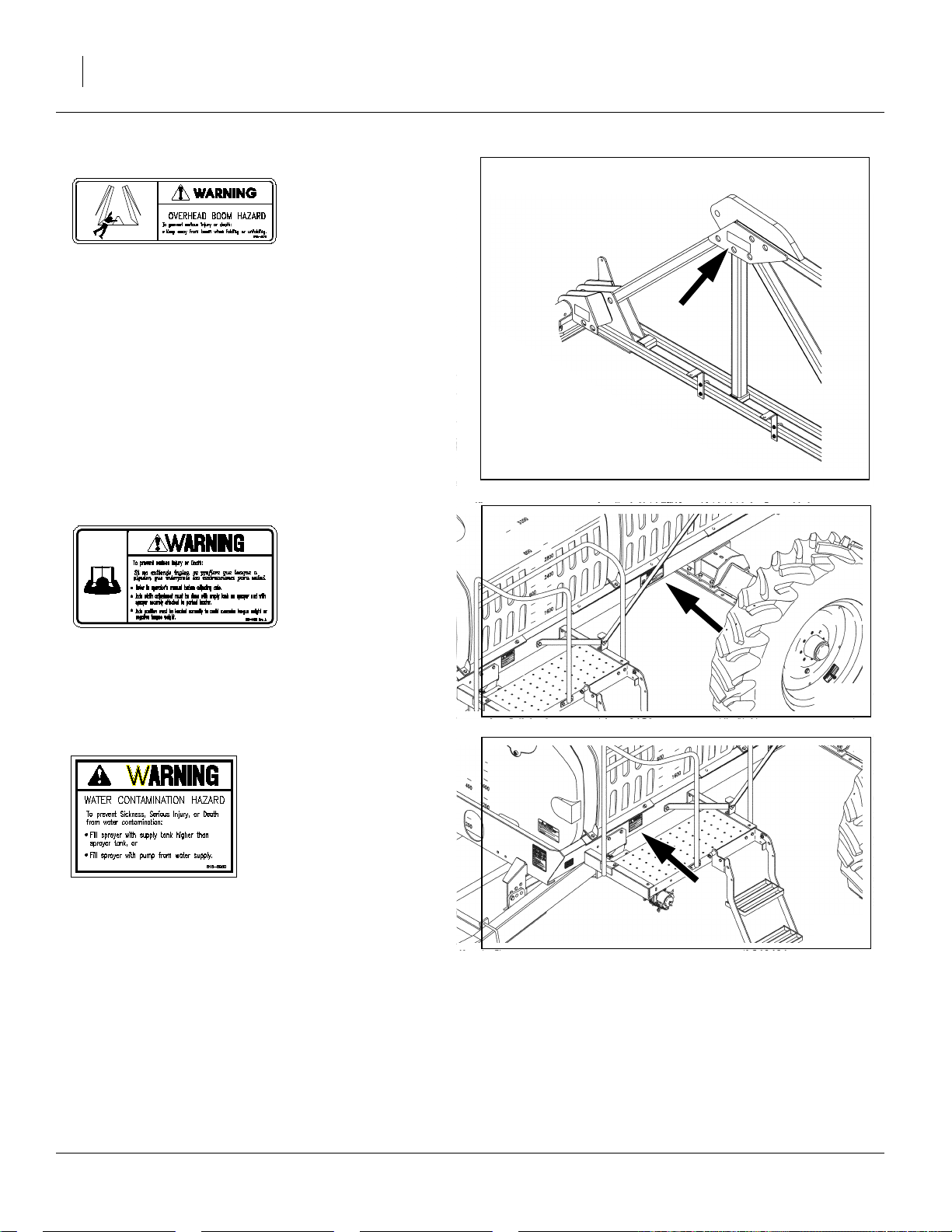
Warning: Overhead Boom
818-467C
rear face of top inboard gusset, each boom inner section;
2 total
20441
Warning: Axle Adjustment
818-548C
left center side of main frame;
1 total
Warning: Water Contamination
818-696C
left side of main frame, at walkboard;
1 total
20377
20377
500-641M 05/10/2012
Page 19
Great Plains Manufacturing, Inc. Important Safety Information 15
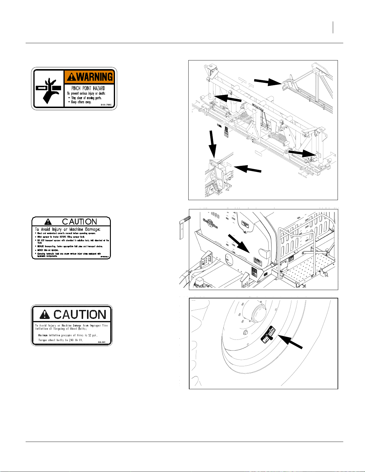
Warning: Pinch Point
818-798C
rear facing on center section pivot tubes (2),
rear face, lower inboard gusset, boom inner section (2),
inside faces of end plates at boom section joint (4);
8 total
20441
Caution: General Sprayer
818-324C
front of tank, lower left;
1 total
Caution: Tire Pressure & Torque
818-365C (SN 1129RR-)
13.6-38 wheel rims;
Valve stem side of tire rim; 1 each wheel
0 or 2 total
848-347C (SN 1130RR+)
320/85R38 Radial Tires
Valve stem side of tire rim; 1 each wheel
0 or 2 total
20377
13838
05/10/2012 500-641M
Page 20
16 TSF1080, TSF1090, TSF1280 & TSF1290 Great Plains Manufacturing, Inc.
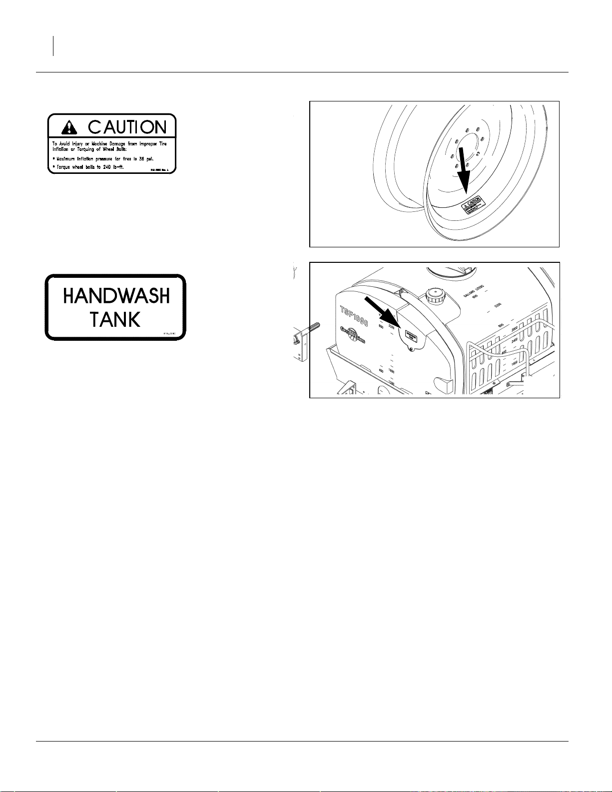
Caution: Tire Pressure and Torque
818-381C
14.9 R46 wheel rims;
0 or 2 total
21519
General: Handwash Tank Location
818-304C
front of hand wash tank, (main tank front top);
1 total
20377
500-641M 05/10/2012
Page 21
Great Plains Manufacturing, Inc. Introduction 17
Introduction
Great Plains welcomes you to its growing family of new
product owners. Your Front Fold Boom Sprayer has been
designed with care and built by skilled workers using
quality materials. Proper setup, maintenance, and safe
operating practices will help you get years of satisfactory
use from the machine.
Document Family
500-641M Operator Manual (this document)
500-641P Parts Manual
509-200M Application Guide
832-038C Nozzle Calculator (U.S.customary units)
832-058C Nozzle Calculator (metric)
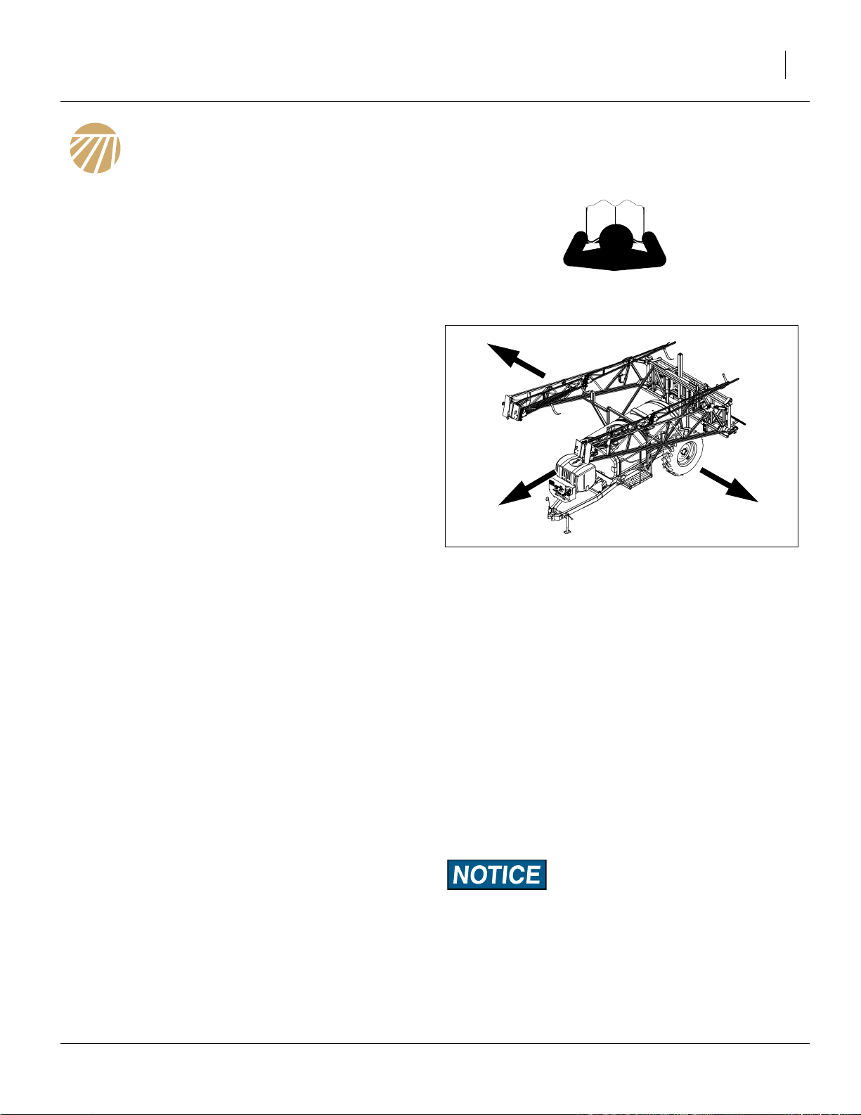
Description of Unit
The TSF1080, TSF1090, TSF1280 & TSF1290 are pulltype implements. They have a working width of 80 or 90
feet (24.4 or 27.4m) depending on model, and are capable of spraying at either 60 feet (18.3m)or the full 80 or
90 feet depending on your application needs. The level
float boom is fully suspended starting with vertical spring
suspension in a 42in (107cm) hydraulic elevator which
provides a wide range of boom height adjustment along
with gas shocks that provide side-to-side stability.
R
Figure 1: TSF1080, TSF1090,
TSF1280 & TSF1290 Sprayer
L
27296
Intended Usage
Use these booms as part of a pressurized sprayer system to apply liquid pesticides, herbicides or fertilizers to
production-agriculture crops only. Do not modify sprayer
for use with attachments other than those approved by
Great Plains.
Models Covered
TSF-1080-3330 1000 Gallon 80 foot 30in spacing
TSF-1080-4820 1000 Gallon 80 foot 20in spacing
TSF-1090-3730 1000 Gallon 90 foot 30in spacing
TSF-1090-5420 1000 Gallon 90 foot 20in spacing
TSF-1280-3330 1230 Gallon 80 foot 30in spacing
TSF-1280-4820 1230 Gallon 80 foot 20in spacing
TSF-1290-3730 1230 Gallon 90 foot 30in spacing
TSF-1290-5420 1230 Gallon 90 foot 20in spacing
Using This Manual
This manual familiarizes you with safety, assembly, operation, adjustments, troubleshooting, and maintenance.
Read this manual and follow the recommendations to
help ensure safe and efficient operation.
The information in this manual is current at printing.
Some parts may change to assure top performance.
Definitions
The following terms are used throughout this manual.
Right-hand and left-hand as used in this manual are
determined by facing the direction the machine will travel
while in use unless otherwise stated.
Paragraphs in this format present a crucial point of information
related to the current topic. Read and follow the directions to:
- remain safe,
- avoid serious damage to equipment and
- ensure desired field results.
Note: Paragraphs in this format provide useful informa-
tion related to the current topic.
05/10/2012 500-641M
Page 22
18 TSF1080, TSF1090, TSF1280 & TSF1290 Great Plains Manufacturing, Inc.
Owner Assistance
If you need customer service or repair parts, contact a
Great Plains dealer. They have trained personnel, repair
parts and equipment specially designed for Great Plains
products.
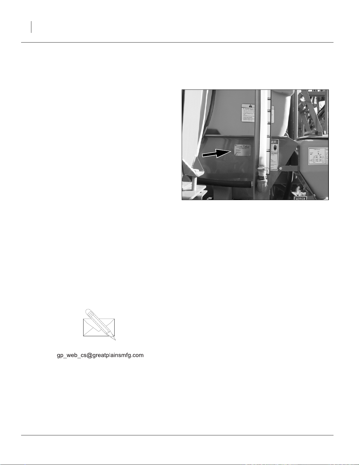
Refer to Figure 2
Your machine’s parts were specially designed and
should only be replaced with Great Plains parts. Always
use the serial and model number when ordering parts
from your Great Plains dealer. The serial-number plate is
located on the front face of the left vertical tube of the 3point frame.
Record your sprayer model and serial number here for
quick reference:
Model Number:__________________________
Serial Number: __________________________
The serial number plate is located on the front of the tank
frame.
Your Great Plains dealer wants you to be satisfied with
your new machine. If you do not understand any part of
this manual or are not satisfied with the service received,
please take the following actions.
1. Discuss the matter with your dealership service
manager. Make sure they are aware of any problems
so they can assist you.
2. If you are still unsatisfied, seek out the owner or general manager of the dealership.
For further assistance write to:
Figure 2
Serial Number Plate
20422
Product Support
Great Plains Mfg. Inc., Service Department
PO Box 5060
Salina, KS 67402-5060
785-823-3276
500-641M 05/10/2012
Page 23

Great Plains Manufacturing, Inc. Preparation and Setup 19
Preparation and Setup
Before You Start
Read and understand the owners manual for your
sprayer. A basic understanding of how the sprayer works
will aid in the assembly, setup and operation of your
sprayer.
Perform these checks before setting up your cross-fold
boom.
1. Read and understand “Important Safety Informa-
tion” on page 1.
2. Check that all working parts are moving freely, bolts
are tight, and cotter pins are spread.
3. Check that all grease fittings are in place and lubricated. See “Lubrication” on page 71.
4. Check that all safety decals and reflectors are correctly located and legible. Replace if damaged. See
“Safety Reflectors and Decals” on page 8.
Hitching Tractor to Sprayer
The standard TSF1080, TSF1090, TSF1280 & TSF1290
sprayers require a tractor with closed center hydraulics. If
the tractor has open center hydraulics, the sprayer must
be adapted to it with an open center conversion kit, 833427C. See page 76.
Negative tongue weight - do not unfold boom before hitching.
When the tank is low or empty, unfolded booms can move the
center of gravity aft of the wheels. This will cause the tongue
to rise, with risk of personal injury and equipment damage.
Hitch Type
If the sprayer has a hydraulic pump, the hitch is a choice
of single tang or clevis. Hitching instructions begin on
page 20.
If the sprayer has a PTO pump, a ball hitch with hitch
plate is standard. Hitching instructions begin on page 21.
You may be severely injured or killed by being crushed
between the tractor and sprayer. Do not stand or place any
part of your body between sprayer and moving tractor. Stop
tractor engine and set park brake before installing the hitch
pin.
Electrocution hazard. To prevent serious injury or death from
electric shock, keep clear of overhead power lines when transporting, folding or unfolding boom. Boom is not grounded.
Electrocution can occur without direct contact. Refer to transport dimensions under “Specifications and Capacities”on
page 79. Do not fold or unfold boom while tractor is moving.
05/10/2012 500-641M
Page 24

20 TSF1080, TSF1090, TSF1280 & TSF1290 Great Plains Manufacturing, Inc.
Hitching with Hydraulic Pump
Refer to Figure 3
A hydraulic pump sprayer has either a single tang or clevis hitch. To change the hitch type, see “Hitches
(Hydraulic Pump Only)” on page 76 for ordering information. The clevis hitch may be inverted if necessary to
obtain ideal hitch height.
Refer to Figure 4
1. Park the sprayer in an open, flat and level area with
the jack in the park position.
2. Back the tractor up to the sprayer, and adjust the
sprayer hitch height with the jack and/or adjust the
tractor hitch height. Back the tractor until the hitches
align.
3. Insert the hitch pin and secure.
4. Skip to “Leveling Sprayer” on page 25.
Figure 3
Tang or Clevis Hitch
20234
Refer to Figure 4 and Figure 5
5. Remo
ve the jack and pin it to the storage stob on the
brace tube above the left wheel axle.
Figure 4
Jack in Parking Position
13811
Figure 5
20402
Jack in Storage Position
500-641M 05/10/2012
Page 25
Great Plains Manufacturing, Inc. Preparation and Setup 21
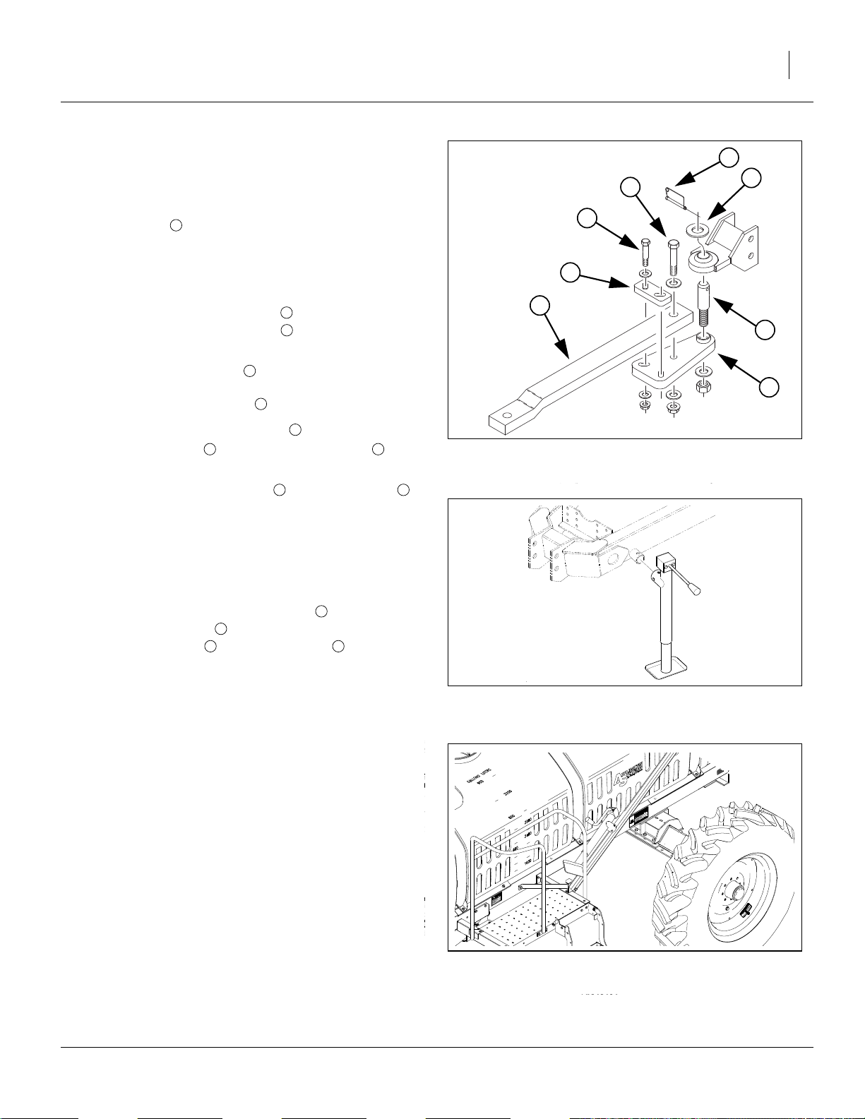
Hitching with PTO Pump
Refer to Figure 6
A PTO pump sprayer has a ball hitch. The hitch parts
include a hitch plate and ball hitch pin to adapt a plain
tractor drawbar to ball hitch use.
If the tractor already has a ball hitch-compatible drawbar,
skip to step 6.
1. Remove the hammer-strap on the tractor.
2. Assemble the ball hitch plate to the drawbar by
placing the 1-8 x 5in long bolt through the drawbar
hole using flat washers on both ends.
3. Place the backup plate on top of the drawbar and
orient the slots so they point in the opposite direc-
tions from the hitch plate slots.
4. Insert the
the backup plate slots and the hitch plate slots.
Secure with washers and flange nuts provided.
5. Insert the ball hitch pin stud in the hitch plate
and secure with washer and 1
6. Park the sprayer in an open, flat, level area with the
jack in the park position.
1
2
3
5
2
3
⁄
-10 x 5in long bolt through washers,
4
5 2
4
6 2
1
⁄
-7 nylon insert nut.
4
7
3
8
4
5
1
6
2
Figure 6
Ball Hitch
20359
Refer to Figure 7 and Figure 8
7. Back the tractor up to the sprayer. Hook up the
sprayer ball hitch onto the stud pin mounted on
the ball hitch plate . Secure the ball hitch with the
large flat washer and the lynch pin .
2
8 7
6
8. Remove the jack and pin it to the storage stob on the
brace tube above the left wheel axle.
Axle Spacing
The TSF sprayers have sliding axles allowing wheel center-lines to be in the range:
N.America: 80 to 120 inches (203 to 305cm)
Export: 203 to 290cm (80 to 114in).
You can set them to match or complement tractor tire
spacing.
This adjustment is most easily done when the sprayer is
mechanically hitched with empty tanks. See “Axle
Wheel Spacing Adjustment” on page 58 for detailed
instructions.
Figure 7
Jack in Parking Position
Figure 8
Jack in Storage Position
13811
20402
05/10/2012 500-641M
Page 26

22 TSF1080, TSF1090, TSF1280 & TSF1290 Great Plains Manufacturing, Inc.
Electrical Connections
For a new sprayer (or moving to a different tractor), first
complete tractor electrical installation (See “Electrical
Installation” on page 28), and installation of any sprayer
Options not factory- or dealer-installed.
Connection Comment
❑ Lights Standard
❑ Raven Controller Standard
❑ Electro-Hydraulics Standard (two connectors)
❑ Foam Marker Optional
❑ Raven G1 Autoboom Optional
❑ Wheel Sensor Optional
❑ Radar Sensor Optional - routine hook-up
necessary only if sensor is
mounted on sprayer
500-641M 05/10/2012
Page 27
Great Plains Manufacturing, Inc. Preparation and Setup 23
Hydraulic Hookup
The standard TSF1080, TSF1090, TSF1280 & TSF1290
sprayer has a single hydraulic connection at the hitch.
Each cart hydraulic function is served by an electrohydraulic control valve at boom center.
If an optional hydraulic pump is installed, there is a second hydraulic connection for the pump, which is located
near the hitch.
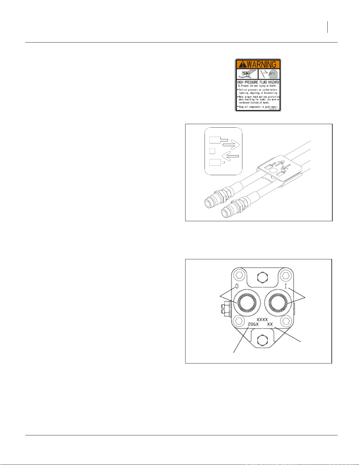
Refer to Figure 9
Both hose sets have labels for flow conventions. These
labels use cylinder Base/Extend and Rod/Retract icons.
Be sure to connect these to the matching tractor
remotes, so that when remote levers are activated as
described in this manual:
a. booms move in the described directions, and
b. pump flow is forward and not reversed.
Sprayer Control Hydraulic Hookup
If the sprayer has a hydraulic pump, and the tractor has
only one circuit capable of continuous flow or only one
capable of adjustable continuous flow, reserve that circuit
for the pump, and use another for the main sprayer functions.
1. Connect the main sprayer hydraulic hoses to suitable
tractor remotes. They are easily identified, as they
pass behind the pump.
Hydraulic Pump Hookup
The hydraulic motor used on all liquid pumps is a 7 gpm
(23 liter/min.) motor. If the tractor used on the sprayer
does not have the capabilities to adjust the remotes
down to this flow, then a Hydraulic Flow Divider Kit must
be installed so that flow can be controlled to prevent
operating the pump at excessive speeds. See a Great
Plains dealer for more information.
Refer to Figure 10
2. The pressure hose coming out of the tractor remotes
must be connected to the motor inlet port (“I” on current pumps; “A” on older pumps, Base end on hose
label), and the return line connected to the motor
outlet (“O” on current pumps, “B” on older pumps,
Rod end on hose label).
3. Before operating, place a stop in the neutral position
for the tractor hydraulics so that the hydraulic lever
can only be moved to the float and down positions.
Refer to the tractor’s operator’s manual or tractor
dealer on information for the neutral stop.
Note: DO NOT move the hydraulic lever into the neutral
position while the hydraulic pump is running. To do
so may cause damage to the hydraulic pump.
4. See page 52 for setting flow rate.
Figure 9
Hose Label
Outlet Port
Motor Model (204N,206N,210N)
Figure 10
Ace Pump Connections
27270
Inlet Port
Date Code
27141
05/10/2012 500-641M
Page 28
24 TSF1080, TSF1090, TSF1280 & TSF1290 Great Plains Manufacturing, Inc.
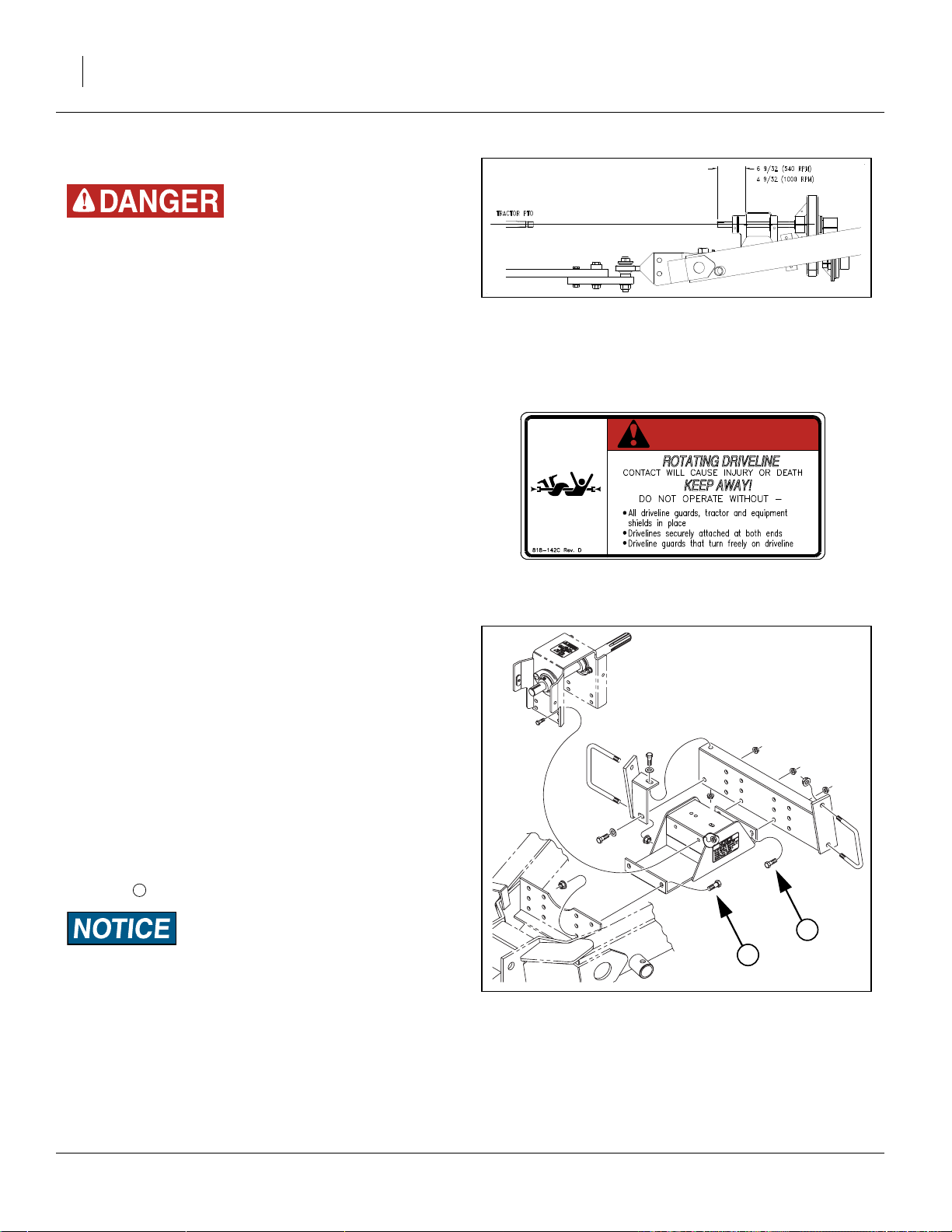
Tractor / PTO Shaft Hookup
Rotating driveline contact can cause death. KEEP AWAY!
Shut down tractor when making connection.
Do not operate without guards attached and driveline securely
attached at both ends.
1. Verify that the tractor drawbar height, and tractor
PTO-to-drawbar spacing, are within ASAE standards, or as shown on page 25.
2. Position the PTO pump on the tractor’s PTO shaft
with the coupler bolt removed on the splined end.
3. Push the coupler of the pump on to align with notch
in the tractor PTO shaft and install bolt.
4. For a 540 RPM pump or a 1000 RPM 1
pump, torque the
ft-lbs.
5. Rotate the PTO shaft by hand to make sure the bolts
clear the PTO shielding.
6. Attach the torque bar chain to the drawbar securely.
7. Hook the tarp strap in such a way that the slack in
the chain is taken up slowly when the PTO is
engaged so the torque bar does not bang.
8. Tie up any loose hoses with cable ties to prevent
hose damage.
1
⁄
in Grade 8 coupler bolts to 105
2
3
⁄
in spline
8
Figure 11
Sprayer PTO Input
DANGER
15837
Refer to Figure 11
9. If ASAE dimensions can be maintained, re-adjust the
tractor drawbar so that the implement end of the driveline centerline, at the bearing housing is level with
or slightly higher than the output centerline at the
tractor. This reduces driveline vibration when turning
a corner.
Refer to Figure 12
10. If insufficient (or no) hitch adjustment is available,
adjust the rear driveline height by loosening the four
4
bolts securing the pump mount.
If, after adjusting the vertical position of the pump drive-shaft,
the drive-shaft is still much higher than the PTO drive-shaft on
the tractor, adjust the hitch up one position and readjust the
pump drive-shaft. See “Leveling Sprayer” on page 25.
Figure 12
Sprayer Pump Mount
4
4
13035
500-641M 05/10/2012
Page 29

Great Plains Manufacturing, Inc. Preparation and Setup 25
Leveling Sprayer
Refer to Figure 13
Check and adjust this only when hitched on level ground.
For proper tank drainage and correct boom height control, the tank mainframe must be sloped forward in operation at an angle of:
1
one to two degrees (1-2
ASAE standards call for the top of the tractor drawbar
2
to be 13 to 20 inches (33 to 51cm) above ground.
Using a level, and yardstick or meter stick, check along
the tank frame. The forward end of the measuring stick
would be lower than the back end by:
yardstick:
meter stick: 2cm
Level may be adjusted either at the hitch, or at the
tongue-to-frame joint (or both).
If a PTO pump is present, the hitch height adjustment
range may be limited. If adjustments are made for PTO
alignment, level needs to be re-checked, and may need
adjustment at the tongue-mainframe joint .
3
⁄
in
4
°).
3
3
Hitch Height
With a hydraulic pump sprayer, make leveling adjustments at the tractor hitch (if possible). Keep the tractor
drawbar height within the ASAE recommended range
(13-20 inches, 33-51cm).
With a PTO pump, make leveling adjustments at the
hitch, but only if:
1
2
3
Figure 13
Leveled Sprayer
27161
5
4
2
Tractor
• both drawbar height ,
• PTO output to drawbar spacing can be kept within
recommendation - and
• the PTO input at the bearing mount (see Figure 11 on
page 24) can be kept at or slightly above the height of
the PTO output.
References:
Drawbar Height 13 to 20 inches 33 to 51cm
2
PTO-to-Drawbar 6 to 12 inches 15.2 to 30.5cm
4
540 PTO Setback 14 inches 35.6cm
5
1000 PTO Setback 16 inches 40.6cm
6
2
4
540 rpm PTO Dimensions
Figure 14
15764
6
4
2
Tractor
Figure 15
1000 rpm PTO Dimensions
05/10/2012 500-641M
15765
Page 30

26 TSF1080, TSF1090, TSF1280 & TSF1290 Great Plains Manufacturing, Inc.
Frame Level Adjustment
Block the wheels, and use a hoist or multiple jacks for this
adjustment. Do not remove the adjustment bolts until the front
end of the tank mainframe is fully supported. Do not remove
the rear pivot bolts.
Refer to Figure 16 (shown with the tongue removed for clarity
- do not remove the tongue for adjustment)
The tongue can pivot about a pair of rear bolts , when
the forward adjustment bolts are removed. Two plates
3
with staggered hole patterns permit re-securing the
2
1
tongue over a range of angles.
1. Securely support the front of the tank mainframe
with a hoist or multiple jacks and stands.
3
1
2. Remove both adjustment bolts .
2
3. Adjust the hoist or jacks up or down until the mainframe is as close as possible to the desired 1
° for-
ward tilt angle.
4. Re-insert and securely fasten the adjustment bolts
2
. Torque these
3
⁄
-10 Grade 5 bolts to per the chart
4
“Torque Values” on page 80.
Leveling Boom
Pinch point hazard. Your fingers, hands or arms could be seriously injured or severed if caught in the folding boom sections.
Shut off tractor and remove key before adjusting shims.
Note: The boom sections must be level across the span
for even spraying.
Refer to Figure 17 and Figure 18
To adjust the inner arm:
1. Unfold the boom. See page 50.
2. Place supports under boom.
3. Loosen bolts holding the plates at the top of the pivots, located between the center section and the inner
boom arms.
4. Add or remove shims as necessary.
Additional shims are available from Great Plains as
part number 506-826D.
5. Retighten bolts.
2
Figure 16
Tongue-Mainframe Adjustment
Figure 17
Boom Level Shims Installed
27163
21762
Figure 18
21805
Boom Level Shims
500-641M 05/10/2012
Page 31

Great Plains Manufacturing, Inc. Preparation and Setup 27
Locking System Setup
Refer to Figure 19
The TSF1080, TSF1090, TSF1280 and TSF1290 have a
locking system for automatic boom locking during folding
and transport. For proper folding, the boom-lock cable
must be tight enough that the lock arms just clear their
stops when unfolded and rest secure against the stop
when folded.
Refer to Figure 20
To
adjust the tension on the boom-lock cable, loosen jam
nut and turn clevis.
Re-tighten jam nut.
Hydraulic Pump Setup
The hydraulic motor used on all liquid pumps is a 7 gpm
(23 liter/min.) motor. If the tractor used on the sprayer
does not have the capabilities to adjust the remotes
down to this flow, then a Hydraulic Flow Divider Kit must
be installed so that flow can be controlled to prevent
operating the pump at excessive speeds. See a Great
Plains dealer for more information.
1. Connect the hydraulic pump to the tractor remotes.
See “Hydraulic Pump Hookup” on page 23 for
details. If no limiter is required, skip to step 7.
Figure 19
Boom Lock Arms
Figure 20
Boom Lock Cable
21760
21761
DO NOT move the hydraulic lever into the neutral position
while the hydraulic pump is running. To do so may cause dam-
Figure 21
Ace Pump Flow Limiter
23395
age to the hydraulic pump.
05/10/2012 500-641M
Page 32

28 TSF1080, TSF1090, TSF1280 & TSF1290 Great Plains Manufacturing, Inc.
Ace Pump Flow Limiter (Option)
The flow limiter (Great Plains part number 829-125C) is
a hydraulic device designed to shut off the flow of
hydraulic oil when a specified flow is exceeded. On tractors with LOAD SENSING (LS) Closed Center hydraulic
systems, this device limits the flow of oil to the Ace motor
and prevents failures due to misapplication.
Newer Case-IH, John Deere, New Holland, and CAT
tractors, present a great potential to turn the motors
beyond their rated speeds. Flows out of the hydraulic
valves can exceed 20 gpm while the motors are rated at
4-11 gpm. The flow limiter protects the Ace motor by
shutting off when hydraulic flows exceed the motor’s
capacity.
The flow limiter should not be used on OPEN Center or
PRESSURE COMPENSATING Closed Center hydraulic
systems. The flow limiter should not be used with a
restrictor orifice.
Flow Limiter Installation
2. Install the flow limiter in the inlet port of the Ace
motor.
3. Shut off boom and agitation valves on the sprayer to
deadhead the sprayer pump flow.
4. Adjust the flow control on the tractor to the minimum
flow setting (typically a “turtle” icon).
5. Move the hydraulic lever to the “Lower/Retract” position.
6. Adjust the flow control on the tractor until the sprayer
system deadhead pressure is 80 psi.
Note: If the flow limiter stops the flow of oil to the motor:
6a) Move the hydraulic lever to the “Neutral” position. This removes the oil pressure from the flow
limiter and allows it to reset.
6b) Adjust the flow control to a lower flow position.
6c) Repeat step 5 and step 6.
Setting Pump Rate
7. To determine the correct setting of the flow rate, start
out with the hydraulic flow control valve at minimum
flow for the outlets that operate the pump.
8. With water in the sprayer tank and in the pump, place
the hydraulic lever in the float position.
9. Open up the sprayer flow control valve to its maximum setting.
10. Start the tractor and engage the pump by placing the
hydraulic lever in the down (forward) position.
11. Once the system builds pressure, close the agitation
valve, shut off the boom section switches, and close
the throttling valves (if applicable).
12. The pump is now at dead head pressure and the
hydraulic control valve must be adjusted so that the
spray pressure reaches 80 PSI maximum on the
nozzle pressure gauge. This process should be done
with the tractor throttle set at normal operating
speed. Mark this setting on the hydraulic control
valve for future reference.
13. Open up the agitation valve and reset the throttling
valve (if applicable). See “Manual Throttle Valve”on
page 32.
Electrical Installation
Prior to first use, complete these items (or verify that they
have been completed), then make the tractor-sprayer
electrical connections (see page 24).
Lights
Refer to Figure 22
The lights and harness are standard, and pre-installed
on the sprayer, but require the common SAE J560B 7pin receptacle on the tractor. If your tractor doesn’t have
this connector, your dealer can assist you with the installation of one.
500-641M 05/10/2012
Tractor Lighting Connector
Figure 22
26467
Page 33

Great Plains Manufacturing, Inc. Preparation and Setup 29
Raven SCS 450
The Raven SCS 450 (Sprayer Control System) is standard, and the sprayer-side components (other than
speed sensor) are pre-installed.
The SCS 450 system consists of a computer-based Control Console, a Speed Sensor, a turbine type Flow Meter
and a motorized Control Valve. The Console mounts
directly in the cab of the tractor for easy operator use.
The Radar Speed Sensor is mounted to the frame of the
tractor or sprayer (wheel drive and speedometer Drive
Speed Sensors are also available.) The motorized Control Valve and Flow Meter mount to the framework supporting the boom valves. Appropriate cabling is furnished
for field installation.
The controller module must be installed in the tractor cab
prior to first use, and must be connected to one or more
tractor systems, including:
• battery power (red:+, black:-)
• existing or new speed sensor, if tractor-mounted (and
if new tractor mount, the sensor must be installed)
Your Great Plains dealer can assist with the installation.
A Raven installation and service manual are provided.
Once installed and connected for the first time, setup and
calibration steps are necessary prior to first field operations. See “Sprayer Calibration” on page 33.
It is important to read and understand the Raven manual
before operating the system.
The operator sets the target volume per area to be
sprayed and the SCS 450 automatically maintains the
flow regardless of vehicle speed or gear selection. A
manual override switch allows the operator to manually
control flow for system check-out and spot spraying.
Actual volume per area being applied is displayed at all
times. The SCS 450 additionally functions as an area
monitor, speed monitor and volume totalizer.
Raven Setup
Current TSF1080, TSF1090, TSF1280 & TSF1290
sprayers include a Raven SCS 450 controller as standard equipment. The controller needs to be installed in
the tractor cab, and cables run to the sprayer, speed sensor and battery prior to first use. Consult the included
Raven manual for installation instructions.
The SCS 450 requires some initial data about your
sprayer and tractor prior to first use.
This data is retained as long as the SCS 450 remains
connected to battery power. If power is removed for electrical work, long term tractor parking or welding, the data
is lost and must be re-entered.
Figure 23
Raven SCS 450 and Cab Cables
27271
Consult the Raven manual for display interpretation and
keyboard procedures.
05/10/2012 500-641M
Page 34

30 TSF1080, TSF1090, TSF1280 & TSF1290 Great Plains Manufacturing, Inc.
The following data is needed for Raven setup:
Model Description BOOM CAL SPEED CAL METER CAL VALVE CAL
TSF-1080-3330
TSF-1080-4820
TSF-1090-3730
TSF-1090-5420
TSF-1280-3330
TSF-1280-4820
TSF-1290-3730
TSF-1290-5420
* Suggested initial value. Refine using calibration procedure in Raven SCS 450 manual.
† This value is printed on a durable tag attached to the meter cable.
‡ This value, typically “2123”, is printed on the label on the valve body.
1000 Gallon 80
foot 30in spacing
1000 Gallon 80
foot 20in spacing
1000 Gallon 90
foot 30in spacing
1000 Gallon 90
foot 20in spacing
1250 Gallon 80
foot 30in spacing
1250 Gallon 80
foot 20in spacing
1250 Gallon 90
foot 30in spacing
1250 Gallon 90
foot 20in spacing
990in (2515 cm)
960 in (2438 cm)
1110 in (2819 cm)
1080 in (2743 cm)
990in (2515 cm)
960 in (2438 cm)
1110 in (2819 cm)
1080 in (2743 cm)
598
598
598
598
598
598
598
598
*
*
*
*
*
*
*
*
Cable Tag
Cable Tag
Cable Tag
Cable Tag
Cable Tag
Cable Tag
Cable Tag
Cable Tag
†
†
†
†
†
†
†
†
Body Label
Body Label
Body Label
Body Label
Body Label
Body Label
Body Label
Body Label
‡
‡
‡
‡
‡
‡
‡
‡
Hydraulic Valve Control
Refer to Figure 24
Install the Fasse valve switch box in a convenient location in the tractor cab.
The Fasse controller requires a connection to the tractor
battery. Use the 6 ft, two-wire red and black cable to connect the hydraulic controls. Connect red wire from each
cable to positive terminal and black wire from each cable
to negative terminal.
If no foam marker is installed, one 4-pin connector is
1
not used.
Foam Marker Control (Option)
This option includes a separate installation and operation
manual.
If ordered with the sprayer, the foam marker is factoryinstalled and cabled to the Fasse harness.
1
Figure 24
Fasse Valve Switch Box
27272
500-641M 05/10/2012
Page 35

Great Plains Manufacturing, Inc. Preparation and Setup 31
Raven Auto-Boom (Option)
This option includes a separate installation and operation
manual.
Refer to Figure 25
Dealer installation of the AutoBoom normally includes on
the sprayer-side components. Install the controller module at a convenient location in the tractor cab.
Connect the unterminated ends of the power lead to a
switched source of 12Vdc power (black-, red+).
Route the control harness to the hitch.
2
1
Spraying Setup
1. Securely hitch the sprayer to the tractor and fasten
the safety chain. Make sure the hitch is adjusted for
1-2° forward tilt of the tank (front of sprayer tank
frame is about 1
that liquid in the tank will drain to the sump.
2. Fill sprayer tank half full with clean water for calibrat-
ing purposes.
3. Hook-up the pump to the tractor. Engage the pump
slowly and check for any leaks.
Hydraulic Pump Setup
1. To determine the correct flow rate to the hydraulic
motor, start with the hydraulic control valve set at a
minimum flow, and the hydraulic lever in the float
position.
2. Open up the sprayer control valve to its maximum
setting. (On the Raven SCS 450 monitor, with the
power switch On, the Rate switch must be placed in
the manual position, and the increase/decrease
switch must be pushed to Increase for 10-12 seconds.)
3. Start the tractor and engage the pump by placing the
hydraulic lever in the down position. Once the system builds pressure on the nozzle pressure gauge,
speed up the tractor throttle to normal operating
speed. Shut off the boom section switches and close
the agitation valve.
4. The pump is now at deadhead pressure and the
hydraulic control valve must be adjusted up until the
spray pressure reaches 80 psi maximum on the nozzle pressure gauge. Mark this setting on the hydraulic control valve for future reference.
1
⁄
in {3.8cm} lower than the rear) so
2
2
1
Figure 25
Raven G1 Autoboom Controller
4. Set the deadhead pressure of the pump at 80 psi
depending on how the pump is driven. See:
Hydraulic Pump Setup or
PTO Pump Setup below.
5. Calibrate sprayer. See:
Sprayer Calibration on page 33
5. Open up the agitation valve.
PTO Pump Setup
1. Open up the sprayer control valve to the maximum
setting. (On the Raven SCS 450 monitor, with the
power switch on, the rate switch must be placed in
the manual position, and the increase/decrease
switch must be pushed to increase for 10-12 seconds.)
2. Start the tractor and engage the PTO pump slowly
with the tractor engine idling. Once the system builds
pressure on the nozzle pressure gauge, shut off the
boom section switches, and close the agitation valve.
3. The pump is now at deadhead pressure. Increase
the engine RPM’s until the spray pressure reaches
80 P.S.I. maximum on the nozzle pressure gauge or
the PTO speed reaches the rated RPM (540/1000).
Never exceed the rated tractor PTO RPM. This is the
RPM needed to spray at to prevent excess pressure
on the sprayer’s plumbing.
4. Open up the agitation valve.
25023
05/10/2012 500-641M
Page 36

32 TSF1080, TSF1090, TSF1280 & TSF1290 Great Plains Manufacturing, Inc.
Manual Throttle Valve
When the manual throttle valve is full open (valve in
23
Figure 28 on page 40), the pressure adjustment can be
very sensitive. The butterfly valve has to move more
16
often causing additional wear.
To decrease the sensitivity, set the manual throttle
adjustment valve as follows:
1. Open the throttle valve so that it is wide open and
there is full flow to the sprayer booms. Open the butterfly valve until it is full open.
2. Close the throttle valve down until the pressure is
about 20 psi greater than the pressure you intend to
spray at. Spraying pressure is determined when calibrating sprayer. Refer to the Application Guide.
With this valve set, it decreases the flow through the
electric ball valve and reduces the sensitivity of the pressure adjustment switch.
500-641M 05/10/2012
Page 37

Great Plains Manufacturing, Inc. Preparation and Setup 33
Sprayer Calibration
Sprayer calibration prepares your sprayer for operation
and diagnoses nozzle wear. This gives you optimum performance from your nozzles and ensures accurate application.
Equipment that may be needed:
• Calibration Container
• Great Plains Nozzle Tip Calculator:
832-038C - U.S. customary units (English), or
832-058C - Metric (English/Russian legends)
• General calculator
• Stopwatch or wristwatch with second hand.
Speed Calibration
Current TSF1080, TSF1090, TSF1280 & TSF1290
sprayers include a Raven SCS 450 controller as standard equipment, and the SCS 450 requires a speed
sensing input, a new or existing wheel sensor or radar.
For a sprayer with the Raven SCS440 controller, perform
the speed calibration procedure from the Raven SCS
450 manual, then resume at “Rate Calibration” on page
34 in this manual.
For a sprayer without a Raven controller, use the following steps.
1. Measure off a 200 foot (or 100 meter) course in the
area to be sprayed or in an area with similar surface
conditions.
2. Select the engine throttle setting and gear that will
be used when spraying. Allow ample approach distance to starting point so that tractor is at desired
speed at start marker. Allow ample overrun area so
that braking is not needed until exiting the course.
3. Hold the speed as you approach the “start” marker,
and check the time required to travel through the
course to the “end” marker.
4. Repeat the above procedure, and average the times
that were recorded. Use these equations to determine the trial ground speed.
CourseFeet 60×
TrialMPH
-------------------------------------------------
=
ElapsedSeconds 88×
Example:
27 seconds over a 200 ft course
200 60×
-------------------
5.05=
27 88×
27165
Speed was: 5.05 mph
TrialKPH
CourseMeters 3.6×
----------------------------------------------
=
ElapsedSeconds
05/10/2012 500-641M
Page 38

34 TSF1080, TSF1090, TSF1280 & TSF1290 Great Plains Manufacturing, Inc.
Rate Calibration
Current TSF1080, TSF1090, TSF1280 & TSF1290
sprayers include a Raven SCS 450 controller as standard equipment, and the SCS 450 system includes a
flow rate sensor in the boom plumbing. This supports
direct real-time readout of the current application rate.
For a newer sprayer, perform the rate calibration procedures from the Raven SCS 450 manual.
For an older sprayer without an SCS 450, perform the following steps.
1. Determine the nozzle rate (gpm or liters/min) at
which your chemical should be sprayed. In determining the rate, and which spray nozzles to use with
your sprayer, you need to know:
Parameter Units Your value Data Source
Nozzle SpacingIn or SpacingCm inch or cm from sprayer configuration (page 17)
Target GpA or LpHa g/ac or liters/Ha From material container or supplier
Intended Mph ok Kph mph or kph From course trial above
Nominal application psi or kg/cm
2
psi or kg/cm
2
from GP slide chart
2. Using this information, calculate the nozzle rate, per
nozzle, per a formula below:
GpA Mph× SpacingIn×
NozzleGpM
----------------------------------------------------------
=
5940
LpHa Kph× SpacingCm×
NozzleLpM
--------------------------------------------------------------
=
60000
Using 0.34 gpm and pressure 30 psi, you would
select a nozzle from your nozzle chart that comes
closest to providing the desired output.
3. Turn on your sprayer and adjust the pressure.
4. While operating the sprayer at desired pressure,
catch the discharge in the calibration container for
one minute. For U.S. customary units, divide the
number of ounces caught by 128 to determine gallons per minute (GpM) per nozzle. 128 fluid ounces
equals one gallon.
SampleOuncesPerMinute
NozzleGpM
--------------------------------------------------------------
=
128
Example:
Nozzle Spacing: 20 in
Speed: 5.05 mph
Pressure: 30 psi
20 5.05 20××
-------------------------------
0.34=
5940
Nozzle Rate = 0.34 Gallons Per Minute
Example:
Sample: 44 U.S. Fluid Ounces in 1 minute
44
-------
0.34=
128
Nozzle Rate = 0.34 Gallons Per Minute
500-641M 05/10/2012
Page 39

Great Plains Manufacturing, Inc. Preparation and Setup 35
5. Check the area rate. You need:
the nozzle spacing (inches or cm) from the sprayer,
the intended field speed from step 4, and
the nozzle GpM or LpM from step 4.
NozzleGpM 5940×
GpA
---------------------------------------------
=
Mph SpacingIn×
Example:
Nozzle rate: 0.34 GpM
Speed 5.05 Mph
Spacing: 20ini
0.34 5940×
------------------------- -
20=
5.05 20×
NozzleLpM 60000×
LpHa
The above procedure assures you of accurate application in the event there is an error in the gauge, nozzle
spacing, nozzle height, tractor speed or nozzle wear.
Since all tabulations are based on spraying clean water,
conversion factors must be used when spraying solutions
which are heavier or lighter than water, or which significantly change the viscosity of water. Consult material
supplier documents for assistance.
-----------------------------------------------
=
Kph SpacingCm×
Area Rate = 20 Gallons Per Acre
Do not calibrate with actual agricultural chemicals. There is
extreme hazard in sample collection, and excess material
would be applied where the sprayer is parked. Instead, rely on
the Rate Controller monitoring, and observed tank consumption rate over the acres/hectares applied.
If sprayer is equipped with a Raven SCS 450 Automatic
Rate Controller, this simple calibration procedure will
also work for verifying speed and proper nozzle output.
All Raven SCS 450 Control Systems require either wheel
drive speed sensor magnets or a radar speed sensor.
Calibration procedures for the speed sensor magnets
can be found in the Raven SCS 450 manual. Calculation
procedures for radar speed sensors are included with
each radar unit dependent on make and model. Make
sure to follow initial programming instructions (Step 3) of
the Raven manual to select either
SP1-(wheel drive sensor), or
SP2-(radar sensor).
05/10/2012 500-641M
Page 40

36 TSF1080, TSF1090, TSF1280 & TSF1290 Great Plains Manufacturing, Inc.
Operations
General Notes For Field Operation
1. Lubricate the sprayer as needed. See “Lubrication”
on page 71.
2. Check the tire pressure in each tire. See “Tire Infla-
tion Chart” on page 79.
3. Securely hitch the sprayer to the tractor and fasten
the safety chain. Make sure the hitch is adjusted so
that the tank contents drain to the sump of the tank.
See “Hitching Tractor to Sprayer” on page 19.
4. Hook-Up the pump to the tractor. See “Hitching
Tractor to Sprayer” on page 19.
5. Fill the hand wash tank with clean water. Have soap
available to wash any exposed areas.
6. Check and clean, if necessary, pump, nozzles and
Whirlfilters®.
7. Check the sprayer initially and periodically for loose
bolts, pins and hose clamps. Check the hoses,
pumps, valves and fittings for leaks.
8. When transporting the sprayer,
DO NOT exceed 20 mph/32 kph and
DO NOT transport with chemical in the tank.
9. NEVER allow anyone to ride on the sprayer.
At the Field
10. Make sure all tank shut off valves are turned on.
11. Calibrate sprayer with a half tank of water only, not
chemical and water. Refer to the calibration procedures in the Application Guide.
12. Adjust the boom height required for the nozzles and
spacing to be used. (Refer to nozzle tables in the
Application Guide.)
Make sure to read the label on the chemical compound that is
to be applied. It is the law.
13. Consider how the chemical will be stored and how
you will dispose of the chemical, according to the
chemical label.
14. When calibrating, filling the tank, or working around
chemicals, wear protective clothing that covers the
body. See “Wear Protective Equipment” on page 2.
Never open a container with your bare hands.
15. When filling the sprayer, it is better to mix the chemical in the field where it is to be applied. Position the
Read and follow chemical manufacturer’s instructions. Some
chemicals and cause serious burns, lung damage and even
death.
sprayer 100 feet from any well or other water source
before mixing the chemical.
16. Safely and carefully add the chemical to the sprayer
tank. By law rinsing of the used chemical container
must be repeated three times. The container should
then be punctured to prevent future use. An alternative is to jet-rinse or pressure rinse the container.
When adding chemical, remain at least 100 feet from
any water well or fresh water source. Follow chemical manufacturer’s recommendations for safe handling of chemicals.
17. Take note of adjoining crops, houses, gardens, people, etc.
18. Apply spray when the wind is 5 mph/8 kph or less.
Minimize drift. Use nozzle tips with the largest practical openings. Operate the sprayer boom at the lowest practical height and lowest practical pressure.
19. If possible, work crosswise to the wind, starting from
the downwind side of the field. This will prevent
heading directly into the chemical fumes.
20. Drive at the same speed you used in your calibration.
Refer to Application Guide. Keep your sprayer calibrated.
21. When turning at the end of a field, make sure you are
correct on the rows so that the boom will not overlap
on crop previously sprayed.
22. Check the sprayer initially and periodically for loose
bolts, pins and hose clamps. Check the hoses,
pumps, valves and fittings for leaks.
23. Check the condition of hoses and connections frequently. Release system pressure before working on
the sprayer by shutting off the pump and flipping the
individual boom section switches on the control box.
Always wear rubber gloves when making repairs or
adjustments.
24. When you are finished spraying, empty the tank and
flush the sprayer with water, including the pump, the
nozzles and the bypass line from the throttling
valves. Properly store the chemical emptied from the
tank or dispose of it per label recommendations.
500-641M 05/10/2012
Page 41

Great Plains Manufacturing, Inc. Operations 37
Operating Checklist
Each time the sprayer is used, check the following:
Check sprayer tire pressure, wear and overall condi-
❑
tion.
Check the tractor’s brakes to make sure they oper-
❑
ate properly.
Make sure all lights and turn signals are working
❑
properly.
❑ Lubricate sprayer as needed.
❑ Booms must be locked in place before transporting.
Inspect tank. Make sure the hitch is adjusted so that
❑
the solution drains to the sump.
❑ Use safety equipment as listed on page 2.
Fill with water and calibrate sprayer BEFORE add-
❑
ing chemical to the tank.
Check the position of the ball valves in the plumbing
❑
to see if they are in the correct position.
❑ Check hoses, pumps and valves for any leaks.
❑ Check nozzle pattern for streaks and non-uniformity.
Check the sprayer initially and periodically for loose
❑
bolts and pins.
Follow “Important Safety Information” on page 1
❑
of this Manual.
❑ Make sure the hand wash tank is full of clean water.
Using Hand Wash Tank
In the event of an accidental spill of chemicals on skin or
in eyes, use the Hand Wash Tank to flush away chemicals.
1. Make sure all persons working with or near the
sprayer know where the tank is located and how to
use it. In the event of a spraying accident, it may be
necessary to find and operate the wash line with
impaired vision.
2. Open the tank valve and use the hose to direct the
clean water on all contaminated areas. Wash all contaminated areas of skin with soap and water. To flush
chemicals from eyes, point the hose and water
stream upward while lowering eyes into the stream
of flowing water.
3. Close the tank valve and refill the hand wash tank.
See “Filling Hand Wash Tank” on page 42.
4. Periodically empty and refill the hand wash tank with
clean water.
Figure 26
Hand Wash Tank Valve
27268
05/10/2012 500-641M
Page 42

38 TSF1080, TSF1090, TSF1280 & TSF1290 Great Plains Manufacturing, Inc.
Transporting
1. Position your sprayer in an open area where you will
not hit power lines, buildings, etc. when the boom is
folded.
2. If transporting empty, do at least fill the hand wash
tank. See “Filling Hand Wash Tank” on page 42.
3. Check that the tractor is capable of towing the
sprayer. The sprayer must weigh no more than 150%
of the tractor weight. The tractor must be rated for
the load. See table at right for sprayer configurations.
4. Make sure the safety chain is securely fastened to
the tractor draw bar and the retaining clip is fastened
to the hitch pin.
5. Never allow riders when transporting the sprayer.
6. When transporting your sprayer, be sure to watch the
height clearances of your folded boom to prevent
damage to the boom and possible injury.
Contact with electrical power lines can cause death by electrocution.
7. Do not exceed 20 mph (32 kph) while transporting
your sprayer.
8. Do not transport sprayer while filled with chemical
mixture.
Note: If a suitable water source exists at the field, trans-
port the sprayer with main tank empty. The weight
of the sprayer more than doubles when the main
tank is full.
To Prevent Serious Injury or Death:
Sprayer Configuration Weight
TSF 1080, Empty 9290 lbs (4214 kg)
TSF 1080, Full 23390 lbs (10610 kg)
TSF 1090, Empty 9340 lbs (4237 kg)
TSF 1090, Full 23440 lbs (10632 kg)
TSF 1280, Empty 9760 lbs (4427 kg)
TSF 1280, Full 27385 lbs (12422 kg)
TSF 1290, Empty 9890 lbs (4486 kg)
TSF 1290, Full 27435 lbs (12444 kg)
WARNING
EXCESSIVE SPEED HAZARD
Do Not exceed 20 mph maximum transport
speed. Loss of vehicle control and/or machine
can result.
818 188C Rev C
Plumbing Overview
Refer to Figure 28
A basic knowledge of how the sprayer is plumbed helps
you understand how to operate your Great Plains
Sprayer. Throughout this manual, the components on
this diagram are described with the terminology labeling
these components.
Five of the valves are labeled on the sprayer decals.
1
Agitator Selector Valve
2
Pump Inlet (Tank) Selector Valve
3
Fill/Spray Selector Valve
4
Product Valve (Tank Fill vs. Induct)
5
Inductor Valve (On/Off)
Other key components are:
Main Tank
10
500-641M 05/10/2012
Flush Tank
11
Main Tank Sump
12
Figure 27
Valve Setting Decal
838-700C
Page 43

Great Plains Manufacturing, Inc. Operations 39
Pump
13
Solution Whirlfilter®
14
Flow Meter
15
Bypass Control Butterfly Valve
16
5-Way Boom Manifold Valves
17
Agitation Gauge
18
Inductor
19
Main Inlet Quick Connect
20
Main Inlet Filter
21
Flush Tank Inlet Quick Connect
22
Manual Throttle Valve
23
Agitator Inlet Shutoff Valves (Normally Open)
30
Main Inlet Shutoff (Normally Closed)
31
Flush Tank Inlet Shutoff (Normally Closed)
32
Main Tank Sump Shutoff (Normally Open)
33
Whirlfilter Cleanout Shutoff Valve (Normally Closed)
34
Inductor Outlet/Tank Inlet Shutoff Valve (N.Open)
35
Valves operate by moving their handles to point at the
function on the decal, or toward the pipe desired on an
otherwise unmarked selector valve. Shut-off valves are
open when the handle is parallel to the piping, and
closed when the handle is perpendicular.
Fluid is drawn from the main tank via the sump
and passes through the pump. The illustration shows
13
10 12
an Ace hydraulic pump, but your pump may be PTO or a
non-standard installation.
From the pump, fluid passes through the solution Whirlfil-
14
ter® , which filters out or grinds up all undissolved
chemical and solid particles. The fluid then passes
through both the flow meter and the bypass control
butterfly valve .
16
The bypass control butterfly valve controls how much
15
16
fluid goes to the boom. This is regulated by the Raven
SCS 450 controller. The fluid passes through the flow
15 17
meter and proceeds to the 5-Way Boom Manifold
valves. If a boom valve is on, the fluid passes to its
respective boom section and is sprayed out the individual
nozzles. See page 83 for a layout of the boom plumbing.
The agitation is set by adjusting the agitation pressure
1
valve while the pump is at operating speed. Refer to
Application Guide to adjust the agitation.
The optional inductor provides convenient pump-
15
driven loading of concentrates into the main tank.
There are tank shut off valves ( - ) at each inlet and
30 35
outlet. Use these to prevent spills and isolate any leaks.
To operate a correctly connected hydraulic pump, push
the hydraulic lever in the “down” position. When you want
to stop the pump, put the hydraulic lever in the “float”
position.
Do not move the hydraulic lever to the neutral position while
the hydraulic pump is running. To do so may cause damage to
the hydraulic pump.
05/10/2012 500-641M
Page 44

40 TSF1080, TSF1090, TSF1280 & TSF1290 Great Plains Manufacturing, Inc.
30
10
17
22
18
32
13
11
14
30
34
23
15
16
21
12
33
31
20
19
35
Figure 28
Sprayer Tank Plumbing
500-641M 05/10/2012
24457
Page 45

Great Plains Manufacturing, Inc. Operations 41
Figure 29
24459
Boom Plumbing System
05/10/2012 500-641M
Page 46

42 TSF1080, TSF1090, TSF1280 & TSF1290 Great Plains Manufacturing, Inc.
Filling Tanks
Always fill the hand wash tank first.
Filling Hand Wash Tank
1
Use only potable or distilled water in the hand wash tank. In
the event of a chemical accident, it may be necessary to spray
this water into your eyes.
Keep the hand wash tank clean, and free of mold and fungus.
After a period of storage, scrub the inside using a mild detergent. Rinse thoroughly.
Plug or cap the hose when parked or stored, to prevent pests
from entering, nesting and plugging the hose. Test the valve
and hose when filling.
To fill the hand wash tank:
Refer to Figure 30
1. Open the filler cap and inspect the condition of the
tank interior. If any debris, sediments, deposits or
growths are seen, scrub and rinse the tank before
use.
2. Unplug/uncap the hose and open the valve .
3. Begin adding clean water at the filler.
If water flows freely out the hose, close the valve.
if water does not flow freely out the hose, stop adding water, and clear the obstruction.
4. Close the valve and complete filling the tank.
1
2
2
Figure 30
Hand Wash Tank Fill
27268
500-641M 05/10/2012
Page 47

Great Plains Manufacturing, Inc. Operations 43
Filling the Flush Tank
The rinse/flush tank fills from the bottom of the tank and
uses a standard 2 inch Cam-Lock coupler , located on
the valve control panel, to connect to the freshwater
22
32
hose.
The flush tank fill line is not connected to the sprayer
pump. A supply pump or pressurized water source is
required to fill the flush tank.
The tank lid is vented and does not need to be opened
for any tank operations other than inspection and cleaning.
To fill the flush tank:
22
Refer to Figure 31, page 38 and Figure 28 on page 40.
1. Check that the hand wash tank is full.
2. Check that all shutoff and cleanout valves are in their
“normal” positions for field operations.
3. Close the ball valve at the flush tank inlet.
4. Set pump inlet selector valve to MAIN TANK.
32
2
5. Connect the supply hose to the quick-fill Cam-Lock
coupler.
Note: If using a positive-displacement pump, open the in-
let valve before starting the pump.
32
6. Turn on the water supply.
7. Open the quick-fill ball valve .
32
8. Stop filling by first stopping the pump, then closing
the inlet valve .
32
Filling the Main Tank
Inspect Main Tank Quad Jets
The main tank has two 4-port nozzles at the bottom. A
portion of the materials to be applied are recirculated
through these jets to evenly mix the chemicals and keep
insoluble components in suspension.
Before adding water to the main tank, inspect the quad
ports to see that their nozzles point toward the tank corners.
If the nozzles are not correctly aligned, see “Quad-Jet
Agitators” on page 69 for adjustment instructions. Follow the instructions carefully, as tank entry may be
required, and can be extremely hazardous.
2
Figure 31
Flush Tank Fill
Figure 32
Quad Jet Orientation
22673
13784
05/10/2012 500-641M
Page 48

44 TSF1080, TSF1090, TSF1280 & TSF1290 Great Plains Manufacturing, Inc.
Adding Water to Main Tank
When filling the sprayer tank, use a check valve or anti-siphon
device to prevent the solution in the tank from infiltrating into
the fresh water source and contaminating it.
31
20
Never add chemicals to an empty tank.
Add chemicals at the field. See page 46.
Note: Tank Straps
The tank straps that wrap around the sprayer tank
may become loose after the first few hours of operation. This occurs when the tank settles in the saddle. Polyethylene tanks are especially susceptible
to this. Retighten the tank straps to secure the tank.
Refer to Figure 33, Figure 34, page 38 and Figure 28 on
page 40.
The main tank fills from the bottom of the tank and uses
a standard 2 inch Cam-Lock coupler , located under
20
the walkboard, to connect to the freshwater hose. The
sprayer must be hitched to the tractor for this operation.
The tank lid is vented and does not need to be opened
for any tank operations.
To fill the tank:
1. Check that the hand wash tank is full.
2. Check that all shutoff and cleanout valves are in their
“normal” positions for field operations. Set all boom
switches to OFF.
Main Fill Using Sprayer’s Pump
The sprayer’s own hydraulic or PTO pump is a centrifugal
type, and may be run with downstream valves closed. It
may require priming if the water level at the source has
no pressure and is below the sprayer.
Figure 33
Main Tank Fill Inlet
1
2
Figure 34
Main Tank Fill with Sprayer Pump
27273
3
27274
3. Close the ball valve at the main tank inlet.
4. Set panel valve to OFF.
31
1
Note: Use of the sprayer’s own pump to fill the tank is
possible only when the optional inductor is
installed. Tank Fill relies on valves and plumbing
5. Set panel valve to MAIN TANK.
6. Set inductor valve to TANK FILL.
2
4
supplied with the inductor.
7. Connect the supply hose to the quick-fill Cam-Lock
coupler .
20
8. Turn on the water.
9. Open the quick-fill ball valve .
31
10. Start the sprayer pump.
11. Stop filling by first stopping the pump, then closing
the inlet valve .
500-641M 05/10/2012
31
Page 49

Great Plains Manufacturing, Inc. Operations 45
Main Fill Using Supply Pump
If relying on gravity, make sure the supply tank is higher than
the sprayer tank.
If relying on an external pump, make sure there is sufficient
pressure at the tank inlet (nominally, at least 10 psi).
1
Failure to do so can cause back-flow from the sprayer tank
causing sickness, serious injury or death from water contamination.
If the supply pump at the water source is a positive displacement type, do not start it until after opening the ball valve
at the inlet.
1. Close the ball valve at the main tank inlet.
2. Set panel valve to MAIN TANK.
3. Set panel valve to SPRAY.
31
2
3
4. Connect the supply hose to the quick-fill Cam-Lock
coupler .
20
5. If using gravity or a pump that is not positive displacement, turn on the water source.
6. Open the quick-fill ball valve .
31
7. If using a positive displacement pump, turn it on.
8. When the tank is filled to the required level:
If using gravity or a pump that is not positive displacement, close the inlet ball valve , then shut off
31
the water source.
If using a positive displacement pump, shut off the
pump, and then close the inlet ball valve .
31
31
2
Figure 35
Main Tank Fill with Supply Pump
3
22673
05/10/2012 500-641M
Page 50

46 TSF1080, TSF1090, TSF1280 & TSF1290 Great Plains Manufacturing, Inc.
Adding Chemicals
Chemicals may be added at the tank top, or by using the
optional inductor.
1. Check that the hand wash tank is full of fresh potable
or distilled water.
2. Before you add the chemical to the tank, make sure
the tank is at least one half full of water. Never add
chemicals to an empty tank. Do not add water after
adding chemicals. Make sure the freshwater hose is
disconnected and the inlet shutoff closed.
3. Check that all shutoff and cleanout valves are set to
their “Normal” field positions. Set all boom switches
to OFF.
4. Park the sprayer so that you will be facing downwind
when adding chemicals at the lid or at the inductor.
5. Keep the spray solution away from all skin. Wear protective clothing and goggles. If the solutions comes
in contact with the body, wash off the contaminated
area with soap and water.
6. Do not smoke while handling chemicals.
7. Store or dispose of unused chemicals as specified
by the chemical manufacturer.
8. Dispose of empty chemical containers properly. By
law rinsing of the used chemical container must be
repeated three times. Puncture the container to prevent future use. An alternative is to jet-rinse or pressure rinse the container.
Do not add chemicals until you are at the field, just prior to
spraying. When you add a chemical, follow the manufacturer’s
instructions for mixing the spray solution in order to achieve
the desired application rate.
Read the manufacturer’s label carefully before handling chemicals.
1
If using liquid fertilizer, or any other chemical corrosive to
brass, install a Great Plains 507-034V gauge protector at the
inlet of the agitation gauge . Failure to do so results in corrosion, eventually causes the gauge to fail, and chemical then
leaks under pressure from the gauge.
18
507-034V
18
Figure 36
Gauge Protector
500-641M 05/10/2012
27297
Page 51

Great Plains Manufacturing, Inc. Operations 47
Inducting Chemicals (Option)
Always turn pump on before opening inductor shutoff valve (at
step 14). Always turn pump off after closing inductor shutoff
valve (at step 19). If the pump is not running, the tank can
drain back through the inductor. The inductor lid is vented,
and cannot prevent overflow.
Refer to Figure 28 on page 40
9. Check that the
35
inductor-outlet/tank-inlet valve
is open.
Refer to Figure 37 and Figure 38
10. At the inductor, set valves:
5
to OFF and
4
(product valve) from OFF to INDUCT.
11. At the valve panel, set valves:
1
to AGITATE,
2
to MAIN TANK, and
3
to SPRAY.
12. Be sure the valve to the tank is open. Start the pump.
Note: The pump recirculates tank contents through a
venturi beneath the inductor tank.
13. Open the inductor lid.
Note: The inductor lid is vented, and the inductor may be
operated with the lid on or off.
1
3
14. Open the inductor shutoff valve and inspect to
5
ensure that there is no back-flow of water from the
tank into the inductor.
15. Add the chemical to the inductor tank.
16. When the required amount of chemical has been
added, and the inductor tank is empty, close the
inductor shutoff valve .
5
2
Figure 37
Panel for Induction
27275
05/10/2012 500-641M
Page 52

48 TSF1080, TSF1090, TSF1280 & TSF1290 Great Plains Manufacturing, Inc.
17. Secure the lid on the inductor tank.
18. Turn off the pump.
19. Set the product valve to OFF.
4
Agitation
Refer to Figure 39
The agitator system bleeds of some of the material flow
and recirculates it through quad jet orifices at the bottom
of the tank. It helps maintain constant concentration with
materials that might otherwise tend to precipitate, sediment or stratify.
5
4
Figure 38
Inductor Valves On
14993
18
1
The agitation valve adjusts the pressure to the agitation nozzles in the tank when set to positions in between
OFF and AGITATION.
Refer to the agitation gauge , and adjust the pressure
to a desired rate. Different chemicals require different
agitation pressures to keep the chemical in suspension.
(see chemical label).
1
18
Foam Marker Tank Fill
Consult the separate manual provided with the marker
system for information on selecting, mixing, loading and
applying marker foam.
Figure 39
Agitation Valve
27275
500-641M 05/10/2012
Page 53

Great Plains Manufacturing, Inc. Operations 49
Boom Operations
2007+ Sprayer Hydraulics
On newer sprayers, the hydraulics use a “live” system.
The tractor hydraulic pump may be left on during sprayer
operations. This requires 5-to-8 gpm flow.
The console toggle switches move up and down from
center off, and are auto-return. They must be held up or
down until an operation is complete.
2006- Sprayer Hydraulics
The tractor circuit is engaged only during the operation,
and the tractor lever determines the direction of cylinder
movement.
The console switches move only up, are detented, and
remain in the selected position until moved. The switch
may be operated before or after lever movement.
Refer to Figure 40
The “live” hydraulic controls come standard to operate
with “closed center” tractor hydraulics. To be used with
an “open center” system a conversion kit must be purchased (part no. 833-427C). To install the conversion kit,
remove the plug from the end of the valve block (#14)
located on the top of the center boom section. Install the
conversion valve and coil into this location. Plug the
electrical cable into the open plug on the valve harness
and the conversion is complete.
14
Figure 40
Fasse Valve Block
29639
Elevator Raising/Lowering
The elevator lifts and lowers the center section of the
boom, which raises and lowers the entire boom.
Refer to Figure 41
Lifting is performed by a hydraulic cylinder controlled by
a solenoid valve, which in turn is controlled by an up-
down/center-stop switch on the boom control panel in
the tractor cab.
The elevator is fully raised for folding.
Lowering is by gravity retraction of the cylinder. When the
switch is toggled down, the hydraulic circuit is put in float.
Lifting and lowering speeds may differ.
Boom Height
After calibrating the sprayer for the specific nozzle to be
used at a desired pressure and tractor speed, the main
field adjustment is the boom height.
Depending on which type of nozzle is being used, set the
boom height so that the correct overlap for that specific
nozzle is achieved. If the crop canopy is taller in some
1
1
Figure 41
Elevation Switches
fields than others, adjust the boom height accordingly.
Refer to the Nozzle Charts in the Application Guide to
determine the height of the boom.
In center-off, the elevator stays at the current position. In
normal field operations, the elevator is set to the desired
height, and left there for the field. Typically this is about
20in (51cm) above the crop canopy.
As necessary, wings are raised and lowered at turns by
the operator, and adjusted to accommodate uneven terrain. The optional Autoboom system is useful on irregular
terrain.
27276
05/10/2012 500-641M
Page 54

50 TSF1080, TSF1090, TSF1280 & TSF1290 Great Plains Manufacturing, Inc.
Boom Unfolding
Negative tongue weight. Do Not unfold the booms if the
sprayer is unhooked from tractor with the sprayer tank empty
or low.
The following procedure should be used to unfold the
boom.
1. Raise left and right Tilt to uppermost position.
2. Unfold left and right inner booms 90˚.
3. Lower left and right tilt to lowest position.
Make sure lock plunger lowers out of the way.
4. Unfold left and right outer booms 180˚.
5. Lower elevator to desired spraying height.
Normal boom use may shift the outer boom support
locks along the inner section. When properly adjusted,
the outer arm plate will snap into the gap between the
lock plates, and the holes line up. Loosen the U-bolts and
reposition brackets as necessary. Adjust cable tension
so the plunger is out of the way when boom is unfolded.
Make sure outer boom cylinder pressure is released and
lock plunger is free to move up and down before unfolding boom.
1
Switches for Unfolding Steps
1
Figure 42
2
45
2 4
27276
Boom Fold
The following procedure should be used to fold the
boom.
1. Raise elevator to top position.
2. Fold left and right outer booms 180˚.
Make sure outer booms snap into locks.
3. Raise left and right tilt to uppermost position. Make
sure lock plunger moves up, locking boom in place.
4. Fold left and right inner booms 90˚.
5. Lower left and right tilt so the booms rest on the
transport supports.
Note: Outer booms will not lock if booms are tilted.
Boom Tilt
Tilt cylinders are single-acting (hydraulic retract, gravity/
float extend).
On the standard TSF sprayers, the booms are level at full
extension.
Tilt is used for storage and for lifting the booms at obstacles and turns.
4
3
Figure 43
Switches for Folding Steps
21
3
4 2
27276
Autoboom Operation (Option)
On TSF sprayers with Autoboom, the Tilt cylinders can
extend below boom level. Boom tilt at full extension is
regulated by gauge wheels with pressure transducers.
Consult the Raven manual for detail on Autoboom installation, setup, adjustments and operations.
500-641M 05/10/2012
Page 55

Great Plains Manufacturing, Inc. Operations 51
60-Foot Spraying
The TSF sprayer is capable of spraying at 60 feet as well
as 80/90 feet. The conversion may be done starting from
a folded configuration, or with booms unfolded.
Refer to Figure 44 (depicting right boom fully unfolded)
The outer boom has an inner section (the “60 foot”
boom) and an outer section (the “80 foot” or “90 foot”
3
boom). The 80/90 section can be folded back, while leaving the 60 foot section extended.
Conversion to 60-Foot, from Folded
1. Raise left and right Tilt to uppermost position.
2
4
5
2. Unfold left and right inner booms 90˚.
1
3. Lower elevation to a position where the end of the
boom is easily accessible.
4. Remove the pin interconnecting the 60ft and 80/
4
90ft boom sections.
5. Manually swing the 60 ft boom section out 180˚
until it seats in the snaps .
6. Replace pin in the 80/90ft section for storage.
7. Unhook cable from the ring on the lock plunger,
4
6
5
2
and hook the cable to the stationary ring on the weldment. This keeps the 80/90ft section locked to the
inner boom .
1
3
8. Turn off sprayer boom sections 1 and 5.
Conversion to 60-Foot, from Unfolded
1. Remove the pin interconnecting the 60ft and
80/90ft boom sections.
3
2. Hydraulically fold the inner section of outer boom
4 2
2
180˚.
3. Replace pin in the 80/90ft section for storage.
4. Unhook cable from lock plunger ring, and hook it
4
6
to the stationary ring on the weldment. This keeps
the 80/90ft section locked to the inner boom .
3 1
5. Turn off sprayer boom sections 1 and 5.
Re-conversion to Full Width
1. Remove pin from storage in the 80/90ft section.
4
7
3
2
6
60ft Boom Operations
While converted to 60-foot operation, do not attempt to unfold
the outer boom sections with the hydraulics, or machine damage will occur.
1
Figure 44
27298
2. Unhook the lock cable from welded ring and hook
6
to plunger ring.
3. Fold 60ft boom and replace pin to tie outer
2 4
boom sections together.
05/10/2012 500-641M
Page 56

52 TSF1080, TSF1090, TSF1280 & TSF1290 Great Plains Manufacturing, Inc.
Operating Pump
Rotating drive line contact can cause death. KEEP AWAY! Do
not operate without guards attached and drive line securely
attached at both ends.
To operate the PTO pumps, engage the PTO shaft slowly
at the tractor’s idle throttle position. Slowly accelerate to
the desired PTO RPM. On a 540 RPM pump, the RPM of
the PTO would be the speed at which the dead head
pressure reaches 80 PSI or 540 RPM. On a 1000 RPM
pump, the RPM of the PTO would be the speed at which
the dead head pressure reaches 80 PSI or 1000 RPM.
Never operate the PTO pump without the tractor PTO shield in
place, and the pump torque bar firmly chained in place.
1. To operate the hydraulic pump, first make sure that
the hydraulic hoses are routed correctly so that the
pump turns in the correct direction. See “Hitching
with Hydraulic Pump” on page 20.
2. To run the pump, push the hydraulic lever in the
“down” position.
3. When stopping the pump, push the hydraulic lever in
the “float” position.
Note: Do not move the hydraulic lever to the neutral posi-
tion while the hydraulic pump is running. To do so
may cause damage to the hydraulic pump.
Unloading Materials
Sprayed chemicals are normally diluted in water for
application, and cannot be recaptured and stored for reuse.
Refer to Figure 45
If a small amount of material remains in the main tank at
completion of spraying, one method of disposing of it is
to apply it to the same fields. To avoid an overdose of
material, reduce the rate or further dilute the tank contents with water (but don’t use the Flush tank water for
this - reserve it for final tank flush and clean-out).
If material must be drained from the tank, rather than
applied via boom, drain at the Whirlfilter sump .
1
1
Do not attempt to drain the main tank by removing the main
sump cap. Potentially hazardous materials will spray in random directions as the clamp is being removed.
500-641M 05/10/2012
Figure 45
Whirlfilter Sump
20403
Page 57

Great Plains Manufacturing, Inc. Operations 53
Tank and Boom Flush
The Tank Rinse and Flush features use the fresh water in
the 100 gallon flush tank to rinse out the main sprayer
tank and boom in the field.
Before operation, make sure the Flush tank is filled with
fresh, clean water.
1. Completely empty the chemical in the main sprayer
tank by turning the agitation off the last pass and
spraying the main tank contents out in the field. To
avoid overdosing, use a higher ground speed or
lower application rate.
2. Make sure all boom valves and pump are turned off.
Refer to Figure 46
3. Set the panel valves to:
agitation valve to “FLUSH”,
tank valve “FLUSH TANK”, and
operation valve “SPRAY”.
4. Operate the pump with the sprayer stationary, and
rinse the tank until
gallons or 126 liters) is consumed and then stop the
pump.
5. With the sprayer pump off, turn the agitation valve
from “FLUSH” to “OFF”.
1
2
3
1
⁄
of the flush tank volume (33
3
Figure 46
Panel for Tank Rinse
1
1
3
2
22672
Refer to Figure 47
6. Rotate the tank valve from “FLUSH TANK” to
“MAIN TANK”.
7. Operate the pump and spray out, in the field just finished, the full 33 gallon (126 liter) volume of liquid
(deposited into the main sprayer tank from the Flush
Tank).
8. Repeat step 2 through step 7 twice more until the
flush tank is empty and the main sprayer tank and
boom has been rinsed completely three times.
9. Reset the agitation pressure before filling the main
sprayer tank again.
2
2
Figure 47
Panel for Boom Flush
1
3
22673
05/10/2012 500-641M
Page 58

54 TSF1080, TSF1090, TSF1280 & TSF1290 Great Plains Manufacturing, Inc.
Parking
The following list should be conducted when unhitching
the sprayer. Important unhitching steps are different for
hydraulic pump hitches and PTO hitches.
See “Storage” on page 56, for more information about
long term storage of the sprayer.
Negative tongue weight. Do Not unhitch an unfolded sprayer.
If the tank is low or empty, the hitch will rise when disconnected from the tractor.
Refer to Figure 48 and Figure 49
1. Fold the booms.
2. If field operations are complete, drain the sprayer
tank of any excess water left from flushing. Dispose
of or store chemical properly by instructions on the
chemical label.
Refer to Figure 50 or Figure 51 on page 55
3. Inspect the hitch.
For a PTO hitch, if the large flat washer is lifted up
against the cross pin ,
7
8
there is negative tongue weight.
For a hydraulic pump hitch, if there is a gap between
the [top] tang and the tractor tongue,
there is negative tongue weight
DO NOT UNHITCH before resolving the negative
tongue weight. Fold booms if not already done.
4. Park the sprayer on a flat, level area, preferably
where it is sheltered from direct sunlight.
5. Remove the jack from the transport position and
move it to the parking position.
6. If the ground is soft, place a board or plate under the
jack to widen the ground contact area.
7. Extend the jack until the weight of the tongue is off
the tractor drawbar and is supported by the jack.
8. Disconnect the electrical lines.
9. Set all tractor circuits to Float. Shut off tractor.
Unplug the hydraulic lines.
Figure 48
Jack in Storage Position
Figure 49
Parking Stand
20402
13811
500-641M 05/10/2012
Page 59

Great Plains Manufacturing, Inc. Operations 55
Unhitching with Hydraulic Pump
Negative tongue weight. Do Not unhitch an unfolded sprayer.
If the tank is low or empty, the hitch will rise when disconnected from the tractor.
Refer to Figure 50
A hydraulic pump sprayer has either a single tang or clevis hitch.
1. Remove the hitch pin.
2. Disconnect the safety chain.
3. Check for any cables or hoses not yet disconnected.
4. Pull the tractor forward.
Unhitching with PTO Pump
Refer to Figure 51
1. Disconnect the PTO drive line.
2. Remove the
long bolt .
3. Swing the ball hitch plate away from the tractor
tongue and loosely re-assemble the backup plate
on it using the bolts, washers and nuts just removed.
4. Check for any cables or hoses not yet disconnected.
5. Check for any cables or hoses not yet disconnected.
6. Pull the tractor forward.
3
⁄
-10 x 5in long bolt and the 1-8 x 5in
4
3
2
4
Figure 50
Hydraulic Pump Hitch
20234
7
3
8
4
5
5
1
6
2
Figure 51
PTO Hitch
20359
05/10/2012 500-641M
Page 60

56 TSF1080, TSF1090, TSF1280 & TSF1290 Great Plains Manufacturing, Inc.
Storage
1. Empty solution from the tank, clean the chemical
inductor (option), and store or dispose of the chemical as recommended by the manufacturer’s chemical
label.
2. Flush the entire sprayer system with clean water.
3. Clean out Whirlfilter®. See “Clean-out the solution
Whirlfilter®” on page 63.
4. Circulate 3 - 5 gallons (11-19 liters) of antifreeze
(Great Plains strongly recommends the use of nontoxic recreational vehicle antifreeze) through the system including the pump, hoses and nozzles.
5. A cast iron pump must be either full of RV antifreeze
or completely empty of all liquid to avoid corrosion. If
the contents of the pump is unclear it is advisable to
drain the pump, remove it, and place it in a warm dry,
environment during the winter.
Regular antifreeze is harmful or fatal to animals and humans.
Use carefully according to the label’s instructions. We strongly
recommend the use of recreational vehicle (RV) antifreeze
which does not exhibit these harmful side effects.
6. Wash off the exterior of the sprayer thoroughly using
a safe solvent or soap and water.
7. Unhitch sprayer per steps under “Parking” on page
54.
8. Remove nozzles, disconnect the control box, and
place them indoors with the pump.
9. Change filters in the tractor cab after finished.
10. Apply grease to exposed cylinder rods to prevent
rust. Be sure to remove grease prior to next use, to
avoid damaging seals.
11. Inspect all parts of the sprayer for wear and rust.
Repair and paint parts as necessary.
12. Store the sprayer in a dry area away from direct sunlight.
500-641M 05/10/2012
Page 61

Great Plains Manufacturing, Inc. Adjustments 57
Adjustments
The following table summarizes the available adjustments. Not all are in this section of the manual.
Adjustment Page Adjustment Affects
Leveling Sprayer 25
Frame Level Adjustment 26 Proper tank drainage and correct boom height control
Leveling Boom 26 Consistent boom height across all rows
Hydraulic Flow Limiter 28 Pump protection and coarse pumping rate
Spraying Setup 31 Correct material pressure and flow
Manual Throttle Valve 32 Maximum consistency of rate control
Agitation 48 Consistent materials solution
Boom Adjustments
Boom Height 49 Correct spray cone overlap for even application
Width Conversion 51 60-foot operation
Elevator Slide 69 Sooth movement and consistent boom level
Break Away Spring 59 Proper boom end response to obstacles
Auto-Boom adjustments ☛ See separate Raven manual
Nozzle Selection ☛ see separate Application Guide and nozzle slide chart
Initial GPM and pressure ☛ see separate Application Guide and nozzle slide chart
Foam setup and rate ☛ see separate manual
Axle Wheel Spacing Adjustment 58 Tire tracks relative to rows and tractor tires
General Field Adjustments
Boom Height
After calibrating the sprayer for the specific nozzle that
will be used at a desired pressure and tractor speed, the
main field adjustment is the boom height. See “Boom
Height” on page 49. Depending on which type of nozzle
is being used, set the boom height so that the correct
overlap for that specific nozzle is achieved. If the crop
canopy is taller in some fields than others adjust the
boom height accordingly. Refer to the Nozzle Charts in
the Application Guide located in this manual to determine the height of the boom needed.
EXAMPLE: A 2.5 Metercone nozzle at 20 inch spacing is
being used. From the Nozzle Chart (refer to the Applica-
tion Guide), a height of 19 to 21 inches above the top of
the crop is required. If the crop is 6 inches off the ground,
the boom height should be set to 25 to 27 inches off the
ground.
Nozzle Pressure
Another area that will need some field adjustments is the
nozzle pressure. As the tank level decreases the boom
pressure may need to be adjusted to keep the pressure
at the same magnitude for what the sprayer was calibrated for if the sprayer is not equipped with a monitor.
Watch the pressure gauge and be aware of changes in
the pressure.
05/10/2012 500-641M
Page 62

58 TSF1080, TSF1090, TSF1280 & TSF1290 Great Plains Manufacturing, Inc.
Axle Wheel Spacing Adjustment
Refer to Figure 52
Axle extension can be adjusted for differing row spacings.
Do not change the fore/aft position of the axle mount, Moving
it forward may result in negative tongue weight even when
folded. Moving it aft increases positive tongue weight and
risks tire contact with boom.
1. Hitch the sprayer on level ground.
2. Measure the current wheel spacing (span) between
tread center-lines.
Note: Also measure the distance from the outer end of
each axle to the mount. Keep these equal, or the
sprayer will pull skewed.
3. Compute the difference between the current and
desired spans. Divide it by two. This is the amount to
extend or retract each axle.
4. Use a hoist or jacks at the left rear corner of the
mainframe to raise the sprayer until the tire on that
side (only) is slightly elevated off the ground.
Leave the other tire firmly on the ground to provide resistance
to lateral frame movement when adjusting an axle.
5. Loosen the bolts joining the upper and lower axle
mounts, starting with the bolts nearest the wheel
being adjusted. Loosen only enough bolts to allow
movement of the axle to be adjusted.
6. Slide the axle in or out to the new setting.
Do not adjust the wheel spacing wider than:
120in (305cm) on North American models, or
290cm (114in) on export models
at tire tread center lines. To do so may cause a falling axle
hazard while the sprayer is in service.
7. Secure the four bolts nearest the tire.
8. Lower the adjusted side.
9. Elevate the right corner, and repeat step 5 through
step 8.
10. Tighten all the bolts to “Torque Values” on page 80.
Figure 52
Wheel Axle Adjustment
13855
500-641M 05/10/2012
Page 63

Great Plains Manufacturing, Inc. Adjustments 59
Break Away Spring
Refer to Figure 53
If an outer boom arm strikes an obstruction, a pair of
spring-load rollers ride up and out of a detent, allowing
the arm to pivot back and upward.
The arm usually re-seats itself automatically. If it does
not:
1. Stop the tractor and set the parking brake.
2. Set hydraulic pump circuit to Float or shut down
PTO.
3. Wear gloves and swing the arm forward until the rollers are back in detent.
Periodically check that break-away springs are compressed to dimension in the figure:
1
5
⁄
in (14cm)
2
1
Adjust spring by turning mounting nut under spring.
More serious obstructions may fail a shear bolt at the
inner arm pivot. See page 64 for replacing this shear
bolt.
Figure 53
Break-Away Spring
1
17001
05/10/2012 500-641M
Page 64

60 TSF1080, TSF1090, TSF1280 & TSF1290 Great Plains Manufacturing, Inc.
Troubleshooting
Problem
Pressure
decreasing
Pressure
fluctuating
Pressure
increasing
Pressure
cannot
increase
No pressure
No pressure
Problem
Area
Between
gauge and liquid supply
Between pump
outlet and liquid
Between
gauge and
nozzle
Pump or electric ball valve
Plumbing Tank shut-off valves off Make sure all tank shut-off valves are open
Pump Hydraulic pump running in the
Pump wearing Rebuild or replace pump
Plugged suction or pump to pressure head hose
Plugged Whirlfilter See “Clean-out the solution Whirlfilter®”on
Plugged gauge Remove the quick disconnect fitting and flush
Check suction hose & fittings for
air leaks. Air in system is indicated by buffs of air at nozzles
Vortex in tank suction Align agitators properly
Cracked pump housing Replace pump housing
Nozzle screens clogged Clean screens
Nozzle orifices plugged Remove material with soft brush or air
Boom hoses becoming clogged Remove obstruction from clogged area
Boom hoses pinched Use cable ties to position hose so it will not
From nozzle charts check liquid
demand against pump capacity
(nozzle requirement + agitation
requirement)
Electric ball valve or gauge not
functional
Pressure adjust switch faulty Test switch & replace if faulty
Fuse is out in control box Replace fuse
Manual pressure adjustment
valve not all the way open
Loose fittings Tighten fittings so pump can prime
Collapsed suction hose to pump Replace hose
Obstruction in suction hose or
tank
wrong direction
PTO pump coupler loose Tighten PTO coupler
Specific Checks Solutions
Clean hose and reduce cause of clogging
page 63.
gauge protector
Remove obstruction from clogged area
kink
Reduce swath width by nozzle reduction;
install smaller nozzles and drive at a lower
rate of speed
Replace or repair
Open the manual pressure valve all the way
and allow the electric ball valve to govern the
pressure
Remove obstruction
Switch hydraulic hoses in the tractor outlet
500-641M 05/10/2012
Page 65

Great Plains Manufacturing, Inc. Troubleshooting 61
Problem
Pressure
cannot
Problem
Area
Pump or electric ball valve
Specific Checks Solutions
Tank agitation restricted Check that the agitator valve is open and that
the liquid is being agitated
decrease
Liquid will
not induct
Inductor
overflow
Switch No. Boot Color Switch Position Hot Wires Pin Out Location Pressure Ports Tank Ports Function
1 Long White Center (off) --------- --------- --------- --------- Off
2 Long Red
Chemical
Inductor
Chemical
Inductor
Left Foam (stat) Red & Wht 4 Cond D-4WP, A-4WP Left Foam Marker
Right Foam (stat) Red & Grn 4 Cond D-4WP, C-4WP Right Foam Marker
Up (mom) Red/Blk & Grn 5-12P, 10-12P C5 Left Tilt Up
Center (off) --------- --------- --------- --------- Off
Down (mom) Red/Blk & Grn & Blk/Wht 5-12P, 10-12P, 9-12P C5 Left Tilt Down
Make sure the valve below the
inductor tank is open
Make sure the pump is in operation and has prime
Make sure the venturi bypass
valve is open
Close valve below inductor tank
until pump is running, has pressure and venturi valve is open
Firing Diagram for Fasse 700-0807-4208 Great Plains 833-423C
Up (mom) Org/Blk & Grn 6-12P, 10-12P C4 Center Up
3 Long White
4 Long Blue
5 Short Green
6 Short Yellow
7 Short Grey
8 Short Red
--------- --------- --------- Blk (zip) --------- --------- --------- Ground
--------- --------- --------- Blk 11-12P --------- --------- Ground
--------- --------- --------- Blu/Blk 4-12P --------- --------- Ground
--------- --------- --------- Blk B-4WP --------- --------- Ground
Center (off) --------- --------- --------- --------- Off
Down (mom) Org/Blk & Grn & Blk/Wht 6-12P, 10-12P, 9-12P C4 Center Down
Up (mom) Wht/Blk & Grn 7-12P, 10-12P C3 Right Tilt Up
Center (off) --------- --------- --------- --------- Off
Down (mom) Wht/Blk & Grn & Blk/Wht 7-12P, 10-12P, 9-12P C3 Right Tilt Down
Up (mom) Grn/Wht & Blu/Wht & Grn A-3P, B-3P, 10-12P C7 C14 Left Outer Fold
Center (off) --------- --------- --------- --------- Off
Down (mom) Grn/Wht & Blu/Wht & Grn & Blk/Wht A-3P, B-3P, 10-12P, 9-12P C14 C7 Left Outer Unfold
Up (mom)
Center (off) --------- --------- --------- --------- Off
Down (mom) Grn/Blk & Red/Wht & Grn & Blk/Wht 12-12P, C-3P, 10-12P, 9-12P C13 C6 Left Inner Unfold
Up (mom) Wht & Blu & Grn 3-12P, 8-12P, 10-12P C2 C9 Right Inner Fold
Center (off) --------- --------- --------- --------- Off
Down (mom) Wht & Blu & Grn & Blk/Wht 3-12P, 8-12P, 10-12P, 9-12P C9 C2 Right Inner Unfold
Up (mom) Red & Org & Grn 1-12P, 2-12P, 10-12P C1 C8 Right Outer Fold
Center (off) --------- --------- --------- --------- Off
Down (mom) Red & Org & Grn & Blk/Wht 1-12P, 2-12P, 10-12P, 9-12P C8 C1 Right Outer Unfold
Grn/Blk & Red/Wht & Grn 12-12P, C-3P, 10-12P C6 C13 Left Inner Fold
29641
05/10/2012 500-641M
Page 66

62 TSF1080, TSF1090, TSF1280 & TSF1290 Great Plains Manufacturing, Inc.
Maintenance and Lubrication
Maintenance
Proper servicing and adjustment is the key to long life for
any implement. With careful and systematic inspection,
costly maintenance, repairs and down time can be
avoided.
Before working on, servicing or making adjustments on
sprayer, always disengage power, shut off tractor engine, make
sure all moving parts have stopped, and all pressure in the system is relieved.
▲ Always wear rubber gloves when making repairs or adjust-
ments.
▲ Make sure all safety equipment mentioned in “Important
Safety Information” starting on page 1, are stored in an
easily accessible place but protected from potential contamination from dust or chemicals.
Sprayer/Boom Maintenance
1. After several hours of operation, check sprayer for
loose bolts, pins and hose clamps.
2. Check hoses, pumps, valves and fittings for leaks.
Always wear rubber gloves when making repairs and
adjustments.
3. Clean nozzles with an air hose with less than 30 psi.
Periodically replace nozzles.
4. Keep elevator slide pads properly adjusted. Lubricating slide pads with grease may cause dirt accumulation that jams elevator. If necessary, use silicone
spray on slide pads.
5. For lubrication points and intervals refer to “Lubrica-
tion” starting on page 71.
6. Check for proper air pressure in the sprayer tires. 22
psi is recommended for the 13.6 x 38 tires.
7. Wash sprayer and boom daily using a safe solvent,
or soap and water.
8. If equipped with a foam marker, clean the air filter on
the air pump no less than once a week, even more
often in extreme conditions.
Equipment Cleanup
Read and follow chemical manufacturer’s instructions. Some
chemicals and cause serious burns, lung damage and even
death.
Nozzles should be cleaned with a low pressure (less
than 30 psi) air hose, and periodically replaced. Haul a
supply tank of water so cleaning of the spray tank and
applicator can be done in the field. NEVER wash tank
out in the yard or at a car wash.
Dispose of leftover chemical in the same manner
described on the manufacturer’s label of the chemical
last used in the sprayer. Rinse out the tank and spray the
rinse water on the last field that was sprayed.
Flush the sprayer with fresh water and spray the water in
the field that was last sprayed. While the sprayer is being
flushed at the field, turn the boom section switches “on”
to flush the nozzles, then turn them “off” to flush out the
bypass lines. Repeat this procedure several times.
General Information
If equipment is to be used in freezing or near freezing
conditions, protect pump and plumbing system by thoroughly draining liquid and pumping antifreeze (Great
Plains strongly recommends the use of recreational vehicle antifreeze) solution through the plumbing system.
The cast iron pump must be either full of RV antifreeze or
completely empty of all liquid to avoid corrosion. If the
contents of the pump is unclear it is advisable to drain
the pump, remove it, and place it in a warm dry, environment during the winter.
Check the condition of the sprayer hoses and clamps. Fix
all leaks by tightening hose clamps or fittings. If the pump
is leaking, refer to the pump maintenance section. If the
hoses are dragging when the sprayer is operated use
cable ties to fix their position. Make sure the hoses do
not bind or kink when the boom is folded or raised. If so,
route the hoses to prevent kinking and binding. If hoses
are damaged, replace as necessary. Periodically check
for loose bolts and tighten.
Inspect all parts of the sprayer for wear and rust. Repair
and paint parts as necessary.
500-641M 05/10/2012
Page 67

Great Plains Manufacturing, Inc. Maintenance and Lubrication 63
Filter Maintenance
There are two filters on the sprayer. One is a canister
type that filters the water entering the tank and the other
is a Whirlfilter® that filters the chemical solution being
sprayed.
These need to be cleaned seasonally, or sooner if flow
restriction is observed.
Clean-out the solution Whirlfilter®
Refer to Figure 54
1. Fill the sprayer tank with water and turn the pump on.
2. With the pump running, slowly open the clean-out
valve and allow the grit to flow out into a bucket.
Clean out the solution Whirlfilter® only when the
sprayer tank is filled with water and no chemical has
been added.
3. Close the clean-out valve and turn off the pump.
4. Dispose of the grit and water in the same manner
described on the manufacturer’s label of the latest
chemical used in the sprayer.
Clean Out Tank Fill Filter
Figure 54
Whirlfilter Clean-Out Valve
15787
Wear chemical gloves and protective clothing. Although used
for adding clean water, the chemical mix in the main tank can
back-wash into this assembly.
Refer to Figure 55
1. Start with an empty sprayer tank.
2. Position a bucket under the plug in the sump cap
2
of the filter. Remove the plug and allow the grit to
1
fall out.
3. Screw the plug back in using pipe thread sealant to
seal the plug.
4. Dispose of the grit and water in the same manner
described on the manufacturer’s label of the latest
chemical used in the sprayer.
If draining the filter does not improve flow:
5. Unscrew the entire sump cap . Remove it slowly
and save the gasket .
3
6. Remove the filter element . Clean or replace it.
2
4
7. Re-assemble the filter. No thread sealant is required
on the main cap threads.
4
3
2
1
Figure 55
Tank Inlet Filter
21808
05/10/2012 500-641M
Page 68

64 TSF1080, TSF1090, TSF1280 & TSF1290 Great Plains Manufacturing, Inc.
Shear Bolt
Refer to Figure 56
Your Great Plains sprayer is equipped with four shear
1
bolts , two each side, to help prevent damage to the
booms. These are located at the inner boom pivot posts
at the ends of the center section. When the boom
encounters an obstruction, both bolts on that side fail,
allowing the boom to swing back.
If a pair of shear bolts breaks, replace them with a pair of
5
⁄
-11 x 3in Grade 5 bolts (Great Plains part 802-160C). If
8
this size and grade bolt is not immediately available, you
may temporarily substitute metric M14x2 Class 8.8 bolts.
Using a lower grade/class bolt causes nuisance shears.
Using a higher grade/class bolt may result in serious
equipment damage.
Inspect these bolts at the start of the spraying season to
insure the bolts have not been weakened through use or
rusting.
Stock a spare nut for each spare shear bolt, as the nut
end of the sheared bolt commonly falls away and is difficult to locate.
1
1
Figure 56
Shear Bolts
22940
500-641M 05/10/2012
Page 69

Great Plains Manufacturing, Inc. Maintenance and Lubrication 65
Pump Maintenance & Repair
The Great Plains pump is designed for long life and service. Through the years there may be a need to replace
the mechanical seal or service some component of the
pump. A mechanical seal may weep slightly, but if it
starts to drip the pump will have to be disassembled.
Before disassembling the pump be sure to wash it out
with fresh water. Refer to the parts manual for the components of the pump.
Refer to Figure 57
If the pump is leaking, before removing it from the
sprayer, run the pump with adequate water in the tank to
diagnose the actual pump problem. If fluid leaks out
between the front suction housing and the rear volute
housing , the housing gasket may be dried out. Give
the gasket adequate time to absorb moisture and
8
6
swell up. If necessary, retighten the volute housing by
alternating on opposite sides until all nuts are torqued
5
8
9
to 16 - 18 ft.-lbs. It is a good practice to apply grease to
both sides of the gasket to prevent shrinkage.
6
If seal replacement is required:
1. Disassemble pump and clean all components.
2. Assemble the ceramic ring seat of the mechanical
7 8
seal into the volute housing of the pump. Make
sure the ceramic seat is positioned square into the
volute housing.
3. Clean off any grease or dirt from pump shaft and
10
dry the shaft so the rubber bellows on the mechanical seal will adhere to the shaft properly when
assembled.
4. Bolt up the pump input bearing housing (not shown)
to the volute housing using bolts , and with
8 2 3 4
spacers (not furnished) for alignment and assembly
of the shaft seal.
5. Assemble the seal without its spring, on the pump
7
shaft by pushing on the inside rubber portion of the
seal using water as the lubrication. The graphite seal
face should touch the white ceramic seat face. The
rubber bellows adhering to the pump shaft should
not protrude more than
1
⁄
in (1.6mm) beyond the
16
stainless steel ring located on the impeller side of the
seal.
6. Assemble the seal’s spring and the impeller, being
careful not to move the mechanical seal that has
been positioned on the pump shaft. Torque the
impeller bolt 16-18 ft-lbs (22-24 N-m).
1
7. Remove the three bolts and spacers. Using gun
grease, lubricate the gasket . Assemble the gasket
6 5
and suction housing using bolts, flat washers
6
and locknuts. Torque nuts 16 - 18 ft./lbs.
Figure 57
11591
Centrifugal Pump Assembly
05/10/2012 500-641M
Page 70

66 TSF1080, TSF1090, TSF1280 & TSF1290 Great Plains Manufacturing, Inc.
Ace Pumps
The Ace pump is designed for long life and service.
Through the years, it may be necessary to replace the
mechanical seal or service components of the pump. A
mechanical seal may weep slightly, but if it starts to drip,
the pump will have to be disassembled. Before disassembly, be sure to wash it out with fresh water.
Ace Hydraulic Pump Seal Replacement
If the pump leaks, before removal from sprayer, run the
pump with adequate water in tank to diagnose the actual
pump problem.
Refer to Figure 58
Ace Pump Disassembly
1. Remove four
of motor. Remove motor and coupler.
2. Remove rear internal bearing snap ring .
3. Remove four
from mounting frame . Remove volute .
4. Remove
5
⁄
in hex head cap screws from rear
16
18
3
3
⁄
in x
⁄
8
3
⁄
in lock nut from shaft . Insert a flat
8
in hex head cap screws
4
8 2
3
19
11
16
file into impeller vane to hold stationary.
Excess torque may damage plastic impellers.
5. Press shaft out of impeller using one
16
5
head cap screw from step 1. Remove impeller ,
key , and rotating seal member .
15
6
5
⁄
in hex
16
5
6. Press shaft/bearing assembly out of frame.
7. Remove stationary seal member by prying out
17
with screwdriver or pressing out from motor end of
9
pump housing.
8. Remove o-ring from shaft groove.
20
Note: If replacing only the pump seal:
a) Press the shaft /bearing assembly into frame.
b) Reinstall rear internal bearing snap ring.
c) Skip to Assembly step 8.
9. Press bearings off of shaft.
10. Remove forward internal bearing snap ring .
11
Figure 58
23373
Ace Hydraulic Pump
500-641M 05/10/2012
Page 71

Great Plains Manufacturing, Inc. Maintenance and Lubrication 67
Ace Pump Assembly
Refer to Figure 59
1. Install forward internal bearing snap ring in
mounting frame .
2. Press in forward bearing from rear side of mounting frame to snap ring .
8
12
8
11
3. Install two external shaft retainer rings with
spacer between on shaft .
14 16
4. Press shaft assembly through forward bearing
until forward shaft snap ring rests against inner
face of forward bearing .
5. Press rear bearing over shaft .
12 16
13
12
6. Insert rear internal bearing snap ring .
7. Slide rubber slinger over shaft and push back
to front bearing .
10 16
12
11
13
12
11
8. Clean old sealant from mounting frame seal bore.
9. Install o-ring in shaft groove.
20
10. Apply non-hardening Type 2 Permatex or similar
under stationary seal flange.
11. Place stationary portion of seal over shaft and
press into seal bore cavity. Use a 1
17 16
3
⁄
in ID pipe or
8
PTO adapter to press seal flange evenly on all sides.
12. Install rotating portion of seal over shaft and oring by hand. The two polished seal faces should
20
6
16
face each other. Avoid contacting polished seal
faces.
13. Insert key in keyway and install impeller on
shaft .
15
16
14. Place lock washer and
and tighten nut .
3
15. Replace volute o-ring or gasket , volute , and
3
⁄
8
3
in x
⁄
in cap screws .
4
four
5 5
3
4 3
⁄
in lock nut on shaft
8
7 2
9
16
16. Position coupler in pump shaft slot and fill cavity surrounding coupler with grease.
17. Install motor by aligning motor tang and coupler
slot. Rotate motor until nameplate faces up.
18. Install four
18
18
5
⁄
in cap screws .
16
19
Figure 59
23373
Ace Hydraulic Pump
05/10/2012 500-641M
Page 72

68 TSF1080, TSF1090, TSF1280 & TSF1290 Great Plains Manufacturing, Inc.
Ace Belt Drive Pump Seal Replacement
Refer to Figure 15
3
1. Loosen 4
the pump volute to the mounting frame. Remove
⁄
in x
8
3
⁄
in long hex screws which attach
4
2
1
volute from mounting frame.
6. Apply a small portion of non-hardening sealant to
new seal case to assure good seal mounting frame
bore. Insert case into bore.
7. Make sure non-rotating seal portion is properly
2. Remove impeller from pump shaft. Use file or similar tool to unscrew in clockwise direction (left hand
thread).
3. Ceramic rotating portion of the seal may now be
removed.
4. Using two screwdrivers inserted in mounting frame
weep holes, pry non-rotating portion of the seal
toward the threaded part of the shaft and finish
removing by hand.
5. If seal case is difficult to extract from the mounting
3
seated by tapping lightly with suitable tool.
8. Place o-ring over pump shaft and slide downward.
Oil face of new ceramic portion with light lubricating
4
oil and place over o-ring and press downward to contact with the stationary portion.
9. Install impeller on shaft (left hand thread). Tighten by
5
inserting a file or similar tool into impeller vane and
turn counter-clockwise while holding shaft steady.
3
10. Replace gasket , volute, and four 4
6
⁄
8
in x
3
⁄
in long
4
hex screws.
frame seal bore, two screwdrivers may be used to
further dislodge the seal.
Figure 60
16141
Ace Belt Drive Pump Seal
500-641M 05/10/2012
Page 73

Great Plains Manufacturing, Inc. Maintenance and Lubrication 69
Elevator Slide
Refer to Figure 61
The polyethylene slides on the elevator can be adjusted
to take out any side-to-side play. Periodically check the
slide pads for wear. As the pads wear, tighten 1/2-inch
bolts on both sides of elevator frame until pads just
touch frame.
Tighten the slides so that there is a minimal amount of
play in the elevator.
When tightening the slides be sure to keep the elevator slide
centered in the elevator mount. If the elevator is adjusted to
one side there can be an interference.
Cycle the elevator a few times to ensure there is no binding and that the slides are sufficiently tightened.
A
B B
Quad-Jet Agitators
Refer to Figure 62
The Quad-Jet agitators are two 4-port nozzle heads in
the sprayer tank. A portion of the tank outflow may be
recirculated to the quad jets to maintain a constant concentration of materials that might otherwise tend to stratify, clump, precipitate or sediment.
The agitator head is oriented at 45 degrees, with reference to the tank ends, so that the water jets are aimed at
the corners of the tank. At completion of tank flushing,
check that the ports are pointing to the corners.
If the ports have shifted, re-adjust them. If they require
frequent adjustment, remove the assemblies and check
for loose fittings.
Confined space, chemical fume and low oxygen hazards.
Review and implement the recommendations of the next section (Tank Entry) before performing any work inside the tank.
Figure 61
Elevator Slide
Figure 62
Quad Jet Agitators
17000
13784
05/10/2012 500-641M
Page 74

70 TSF1080, TSF1090, TSF1280 & TSF1290 Great Plains Manufacturing, Inc.
Tank Entry
Normal use of the sprayer and routine maintenance do
not require entry.
▲ You can be overcome by hazardous fumes very quickly even
in an empty tank with the lid open.
▲ Oxygen levels may be insufficient.
▲ Do not enter a tank for loading material.
▲ Do not enter a tank for unloading material.
▲ Do not enter a tank for routine cleaning.
▲ Never enter a tank without at least one trained and
equipped attendant present.
Never enter a tank for any reason unless you fully comply with applicable laws, regulations, rules, agreements,
and the instructions in this section. Where applicable
laws, regulations, rules, agreements contradict an
instruction below, do not follow that instruction.
Depending on use, the TSF sprayer tank may be or
become a “permit-required confined space” under U.S.
OSHA regulations (29 CFR 1910.146) and similar regulations, statutes, insurance agreements and local business policy. A written policy and permitting process may
be required for any tank entry.
Tank entry may be necessary in some unusual circumstances, such as:
• agitator nozzle alignment;
• clean-out nozzle repair/replacement; or,
• removal of obstructions not susceptible to fishing or
pumping out from the open lid.
Should such a situation arise, observe the following precautions:
1. Evaluate the hazards
Review the material safety data sheets (MSDS) for
any chemicals used in the tank since it was last thoroughly cleaned, and the most recent materials even
if the tank was subsequently cleaned. Retain the
MSDS information for any medical treatment that
might be required.
2. Designate or engage a team
Tank entry is never a single-person activity. At least
one attendant/observer is necessary. Give priority to
individuals already trained in confined space operations. Designate a leader (who will not be the
entrant) with authority to terminate the activity.
3. Protect the team
Obtain the necessary safety equipment specified for
confined space exposure to those materials, paying
particular attention to respiratory support and protection. This may include contaminant detection equipment and positive ventilation to refresh air in the
tank.
4. Equip the team
At least one attendant must be equipped with communications capability, to summon outside aid in the
event that the tank worker is overcome. Equip the
entrant with a safety harness and safety line.
5. Train the team
Review the hazards. Review the procedures. Understand the use of the protective equipment. Know the
steps to take in emergencies. Practice them. Train
the observer to summon aid, and not attempt tank
entry if the entrant is overcome.
6. Secure the cart
Block the cart wheels to prevent movement.
7. Empty the tank
Follow the steps at “Unloading Materials” on page
52. If a blockage makes this impossible, use an
external pump line to remove as much material as
possible without performing a tank entry. Pump until
at least some material is exiting the clean-out port.
Leave the clean-out port open.
8. Clean the tank
Perform normal tank flushing, per “Tank and Boom
Flush” on page 53. From the outside at the walkboard, power-wash the inside of the tank. Use a mild
detergent sprayer. Rinse thoroughly.
9. Air the tank
Leave the tank lid and clean-out door open, and do
not commence work until the rinse water has completely evaporated.
10. Plan the work. Work the plan.
Postpone the work if any team members, equipment
or other resources are missing, or weather/lighting
conditions are not favorable. Terminate and evacuate
if any unexpected situations arise.
500-641M 05/10/2012
Page 75

Great Plains Manufacturing, Inc. Maintenance and Lubrication 71
Lubrication
Multipurpose
spray lube
Elevator Slide
Multipurpose
grease lube
10
pads and exposed vertical tube bearing surfaces
Type of Lubrication: Dry graphite or NLGI grade 2
grease
Quantity: coat surface lightly
Swing Arm Weldment
10
Multipurpose
oil lube
Intervals (service hours) at
which lubrication is required
50
27384
2 zerks each side; 4 total
Type of Lubrication: Grease
Quantity: Until resistance is felt
Ace Pump: (if applicable)
1 zerk
(located on belt idler arm casting)
Type of Lubrication: Grease
Quantity: 3 pumps
10
Null4:
20417
15979
05/10/2012 500-641M
Page 76

72 TSF1080, TSF1090, TSF1280 & TSF1290 Great Plains Manufacturing, Inc.
PTO Pump: (if applicable)
10
1 zerk
(located on rear gear case cover, and marked by decal)
Type of Lubrication: Grease
Quantity: 5 pumps
12229
Inner Pivot Tube
30
2 zerks each side (top and bottom); 4 total
Type of Lubrication: Grease
Quantity: Until resistance is felt
Base Pivot, Inner Fold Section
30
1 zerk each side; 2 total
Type of Lubrication: Grease
Quantity: Until resistance is felt
Null4:
20418
Null4:
20419
500-641M 05/10/2012
Page 77

Great Plains Manufacturing, Inc. Maintenance and Lubrication 73
Base Pivot, Outer Fold Section
30
2 zerks each side; 4 total
Type of Lubrication: Grease
Quantity: Until resistance is felt
Null4:
20420
Base Pivot, Outer Fold Section
30
1 zerks each outer break-away boom; 4 total
Type of Lubrication: Grease
Quantity: Until resistance is felt
Transport: Wheel Bearings
Seasonally
2 bearings each axle; 4 total
Type of Lubrication: Grease
Quantity: repack
27299
13854
05/10/2012 500-641M
Page 78

74 TSF1080, TSF1090, TSF1280 & TSF1290 Great Plains Manufacturing, Inc.
Options
Autoboom
The Raven G1 Autoboom system consists of:
• adjustable gauge wheel assemblies with pressure
transducers for lift sensing,
• on-sprayer hydraulic control valve assembly, plumbed
into existing sprayer lines, and;
• a cab control module with harness connections to
valve block, sensors and power.
The standard kit is for tractors with closed center hydraulics. The sprayer-side components of the Autoboom are
dealer-installed.
Description Part Numbers
RAVEN G1 AUTOBOOM ASY 833-421C
G1 OPEN CENTER CONV. 833-422C
The Autoboom includes separate installation and operation manuals.
Figure 63
Raven G1 Autoboom Controller
25023
Axles and Wheels
All sprayers are available with North American or Export
axles. Sprayers shipped by intermodal container must
have export axles. Export models have shorter axle
tubes. Available wheel-to-wheel span is:
N.America: 80 to 120 inches (203 to 305cm)
Export: 203 to 290cm (80 to 114in).
1000 gallon sprayers (TSF-1080/1090) have a further
choice of:
13.6x38 wheels and two-step ladder, or
14.9 R46 wheels and three-step ladder.
1200 gallon sprayers (TSF-1280/1290) use only 14.9
R46 wheels.
Description Option
13.6-38 Wheel, N.America
SN1129RR-
13.6-38 Wheel, Export 72 504-046A
14.9 R46 Wheel, N.America
SN1129RR-
14.9 R46 Wheel, Export 73 504-047A
320/85R38 WHEEL & AXLE ASSY
SN1130RR+
320/85R38 WHEEL & AXLE ASY EXP
SN1130RR+
70 504-037A
71 504-036A
70 504-051A
71 504-052A
Part
Numbers
Figure 64
Wheels, Axles and Ladder
27300
For setup, see “Axle Wheel Spacing Adjustment” on page 58.
500-641M 05/10/2012
Page 79

Great Plains Manufacturing, Inc. Options 75
Calibration Accessories
Your sprayer includes a nozzle calculator and sample
container. Export sprayers include a metric nozzle calculator.
Description
CALIBRATION CONTAINER 817-199C
NOZZLE TIP CALCULATOR 832-038C
NOZZLE TIP CALCULATOR-METRIC 832-058C
Part
Numbers
Chemical Inductor
The inductor eliminates the need to climb the walkboard
and add materials directly to the tank water. It provides a
convenient and safe dedicated ground-level 3-gallon
(11.3 liter) tank.
If ordered with a new TSF1080, TSF1090, TSF1280 &
TSF1290 (option #61), the inductor is pre-installed prior
to delivery.
Description Option
CHEMICAL INDUCTOR ASY 61 502-144K
For operations, see “Chemical Inductor” on page 75.
The inductor adds 38 lbs (17 kg) to the empty weight of
the sprayer. When fully loaded with material, the inductor
adds 83 lbs (38 kg) to the sprayer.
Part
Numbers
High Volume Foam Marker
This kit includes a 25 gallon tank with integral pump,
mounting hardware, plumbing, nozzles and cab control.
Dispensers are provided for both left and right booms.
If ordered with a new TSF1080, TSF1090, TSF1280 &
TSF1290 (option #52 or 53), the foam marker tank is preinstalled prior to delivery. The foam marker includes a
separate installation and operation manual.
Figure 65
Calibration Accessories
Figure 66
Inductor Components
27165
22668
Description Option
FOAM MARKER KIT 80/90FT 52 502-147A
FOAM MARKER 60/80, 60/90FT 53 502-153A
The foam marker adds 114 lbs (52 kg) to the empty
weight of the sprayer. When fully loaded, it adds 314 lbs
(91 kg) to the sprayer.
05/10/2012 500-641M
Part
Numbers
Figure 67
Foam Marker Components
22703
Page 80

76 TSF1080, TSF1090, TSF1280 & TSF1290 Great Plains Manufacturing, Inc.
Gauge Protector
This fitting protects the control panel pressure gauge
from corrosive chemicals added to the main tank.
Description Part Number
GAUGE PROTECTOR ASSY 507-034V
See page 46 for installation location.
507-034V
Hitches (Hydraulic Pump Only)
Sprayers with hydraulic (not PTO) pumps have a choice
of tang or clevis hitch.
Description Option
Clevis Hitch 62 500-007H
Tang Hitch 63 500-008H
For setup, see “Hitching with Hydraulic Pump” on
page 20.
Part
Numbers
Open Center Hydraulic Kit
2007+ sprayers require a tractor with closed center
hydraulics. Use this kit to convert the sprayer for use with
an open center tractor.
63
Figure 68
Gauge Protector
62
Figure 69
Tang or Clevis Hitch
27297
20234
Description Part Number
FASSE LIVE HYD OPEN CTR KIT 833-427C
For installation location, see page 81.
Figure 70
Open Center Kit
500-641M 05/10/2012
27385
Page 81

Great Plains Manufacturing, Inc. Options 77
Pumps
The standard TSF1080, TSF1090, TSF1280 & TSF1290
does not include a pump. Optional hydraulic or PTO
pumps are available.
Ace Hydraulic Pump
If ordered with a new TSF1080, TSF1090, TSF1280 &
TSF1290 (Option 35), the pump is pre-installed prior to
delivery.
Description Option
Part
Numbers
PUMP - TS HIGH VOL HYD 35 507-105A
For operation, see “Operating Pump” on page 52.
Pump kit weight: 40 lbs (18 kg)
Ace Flow Limiter
On tractors with LOAD SENSING (LS) Closed Center
hydraulic systems, this device limits the flow of oil to the
Ace motor and prevents failures due to misapplication.
Your Great Plains dealer can assist with installation of
the flow limiter.
Description
FLOW LIMITER VALVE - ACE PUMP 829-125C (2006-)
FLOW LIMITER VALVE - ACE PUMP 829-131C (2007+)
Part
Numbers
For use, see “Ace Pump Flow Limiter (Option)” on
page 28.
Ace PTO Pumps
Pumps are available for 540 rpm PTO (#33) or 1000 rpm
3
1
⁄
in PTO (#34).
8
The pump kit includes required hitch components.
If ordered with a new TSF1080, TSF1090, TSF1280 &
TSF1290 (see option #s above), the pump is preinstalled prior to delivery.
Figure 71
Hydraulic Pump Components
Figure 72
Ace Flow Limiter
27301
23395
Description Option
PUMP TS ACE150 540 DRIVE
SHAFT
PUMP TS ACE 1000 1-3/8 DR
SHFT
33 507-083A
34 507-084A
Part
Numbers
Pump kit weights:
507-083A 152 lbs (69 kg)
507-084A 167 lbs (76 kg)
05/10/2012 500-641M
Figure 73
Ace PTO Pump
20358
Page 82

78 TSF1080, TSF1090, TSF1280 & TSF1290 Great Plains Manufacturing, Inc.
Speed Sensors
The standard TSF1080, TSF1090, TSF1280 & TSF1290
does not include a speed sensor, which is required by
the Auto-Control system to regulate material rate based
on current speed. Optional sensors kits detect speed via
wheel rotation or radar ground speed.
If the tractor already has a speed sensor, a “Y” cable is
available to share its signal with the Raven SCS 450 controller. Otherwise, order one of the following:
Description Option
TSF RADAR KIT 43 509-289A
TSF WHEEL SENSOR MNT KIT 42 509-288A
Your Great Plains dealer can assist you with installation
Part
Numbers
Radar Speed Sensor
This easy-to-install precision sensor may be mounted on
either the tractor or the sprayer. It is compatible with a
wide variety of agricultural cab controls, and may be
used for implements other than the TSF1080, TSF1090,
TSF1280 & TSF1290 when not spraying.
Raven Wheel Speed Sensor
This economical speed sensor is sprayer-mounted. Consult your dealer for installation.
Y-Cable
If your tractor already has a speed sensor, it may be
compatible with the Raven SCS 450 controller. Consult
your dealer for advice.
If the sensor is compatible, these cables share the signal
between your existing tractor systems and the Raven
SCS 450.
Figure 74
Radar Speed Sensor
Figure 75
Wheel Speed Sensor
Figure 76
Y Cable
27153
27154
27155
Part Numbers Comment
115-0159-432 TRW radar, Case IH
115-0159-519 DICKEY-john or Magnavox radar, John Deere 1990 or later
115-0159-518 DICKEY-john radar, Cat Challenger (Model 65 & 75)
115-0159-517 DICKEY-john radar, Case IH
115-0159-529 DICKEY-john radar, Ford/White
115-0159-627 DICKEY-john radar, Cat Challenger (Model 65C, 75C-Mod, D-Mod Row Crop 35,45,55)
115-0159-700 DICKEY-john or Magnavox radar, John Deere 7000/8000/9000 Series (2WD or MFWD)
117-0159-462 Magnavox radar, other than John Deere
117-0159-463 TRW radar, other than Case IH
500-641M 05/10/2012
Page 83

Great Plains Manufacturing, Inc. Appendix 79
Appendix
Specifications and Capacities
TSF-1080 TSF-1090 TSF-1280 TSF-1290
Boom Width 60 or 80 feet
18.3 or 24.4m
Nozzle Spacing 20 or 30in (51 or 76cm)
Nozzle Count 48 (20in) or 33 (30in) 54 (20in) or 37 (30in)
Main Tank Capacity 1000 gallons (3785 liters) 1250 gallons (4731.7 liters)
Flush Tank Capacity 100 gallons (379 liters)
Hand Wash Tank Cap. 5 gallons (18.9 liters)
Marker Foam Tank Cap. 25 gallons (95 liters)
Tractor Requirement 100 hp (75 kW)
Closed Center
*
Hydraulic Circuits
Empty Weight 9290 lbs (4214 kg) 9340 lbs (4237 kg) 9760 lbs (4427 kg) 9890 lbs (4486 kg)
Full Weight 23390 lbs (10610 kg) 23440 lbs (10632 kg) 27385 lbs (12422 kg) 27435 lbs (12444 kg)
Working Width 83 ft (25.3m) 93 ft (28.4m) 83 ft (25.3m) 93 ft (28.4m)
Transport Width 12 ft (3.7m)
Transport Height 13 ft 6 in (4.1m)
Length 22 ft 5in (6.8m)
Clearance
‡
Wheel Spacing North American models: 80 to 120 inches (203 to 305cm)
Tire Size
Pumps
††
320/85R38
Ace Tractor mounted high volume PTO pump - 540 RPM,
Ace Tractor mounted high volume PTO pump - 1000 RPM 1
customer-provisioned 90 gpm at 30 psi (341 liters/min at 207 kPa)
* An optional kit (833-427C) is available for open center tractors. See page 76.
† If tractor cannot restrict flow to 6 gpm, purchase a flow-control kit from your Great Plains dealer.
‡ Lowest part of hitched sprayer is the tractor side of the hitch.
** May be upgraded by Option to 14.9 R46.
†† Standard sprayer does not include a pump.
60 or 90 feet
18.3 or 27.4m
60 or 80 feet
18.3 or 24.4m
One hydraulic remote (with PTO pump)
Two hydraulic remotes (with hydraulic pump)
28 in (71cm)
Export models: 203 to 290cm (80 to 114in)
**
14.9 R46
Ace Hydraulic,
60 or 90 feet
18.3 or 27.4m
†
3
⁄
in spline, or
8
Tire Inflation Chart Tire Warranty Information
Wheel Tire Size Inflation
Transport 13.6-38 6 Ply Tubeless
Transport
14.9 R46 4* 10 Ply
Radial
Transport 320/85R38 Radial
05/10/2012 500-641M
22 psi
152 kPa
36 psi
221 kPa
52 psi
359 kPa
All tires are warranted by the original manufacturer of the tire.
Tire warranty information is found in the brochures included
with your Operator’s and Parts Manuals or online at the manufacturer’s websites listed below. For assistance or information, contact your nearest Authorized Farm Tire Retailer.
Manufacturer Website
Firestone www.firestoneag.com
Gleason www.gleasonwheel.com
Titan www.titan-intl.com
Page 84

80 TSF1080, TSF1090, TSF1280 & TSF1290 Great Plains Manufacturing, Inc.
Torque Values
Bolt
Size
in-tpi
1
⁄4-20
1
⁄4-28
5
⁄16-18
5
⁄16-24
3
⁄8-16
3
⁄8-24
7
⁄16-14
7
⁄16-20
1
⁄2-13
1
⁄2-20
9
⁄16-12
9
⁄16-18
5
⁄8-11
5
⁄8-18
3
⁄4-10
3
⁄4-16
7
⁄8-9
7
⁄8-14
1-8
1-12
1
⁄8-7
1
1
1
⁄8-12
1
1
⁄4-7
1
1
⁄4-12
3
⁄8-6
1
3
1
⁄8-12
1
1
⁄2-6
1
1
⁄2-12
Bolt Head Identification
Grade 2 Grade 5 Grade 8 Class 5.8 Class 8.8 Class 10.9
a
b
d
N-m
ft-lb
7.4 11 16
8.5 13 18
15 24 33
17 26 37
27 42 59
314767
43 67 95
49 75 105
66 105 145
75 115 165
95 150 210
105 165 235
130 205 285
150 230 325
235 360 510
260 405 570
225 585 820
250 640 905
340 875 1230
370 955 1350
4801080 1750
540 1210 1960
680 1520 2460
750 16802730
890 1990 3230
1010 2270 3680
1180 2640 4290
1330 2970 4820
N-m N-m
5.6 8 12
61014 5 8 11
11 17 25 12 19 27
13 19 27 13 21 29
20 3144 243953
22 3549 294562
324970 426793
365578 44 70 97
49 76 105 66 77 105
55 85 120 68 105 150
70 110 155 73 115 160
79 120 170 105 165 230
97 150 210 115 180 245
110 170 240 145 230 300
170 265 375 165 260 355
190 295 420 205 325 450
165 430 605 230480 665
185 475 670 355 560 780
250 645 910 390 610 845
275 705 995 705 1120 1550
355 795 1290 785 1240 1710
395 890 1440 1270 1950 2700
500 1120 1820 1380 2190 3220
555 1240 2010
655 1470 2380
745 1670 2710
870 1950 3160
80 2190 3560
9
Bolt Head Identification
Bolt
Size
ft-lb ft-lb ft-lb ft-lb ft-lb
mm x pitch
M 5 X 0.8
M 6 X 1
M 8 X 1.25
M 8 X 1
M10 X 1.5
M10 X 0.75
M12 X 1.75
M12 X 1.5
M12 X 1
M14 X 2
M14 X 1.5
M16 X 2
M16 X 1.5
M18 X 2.5
M18 X 1.5
M20 X 2.5
M20 X 1.5
M24 X 3
M24 X 2
M30 X 3.5
M30 X 2
M36 X 3.5
M36 X 2
a. in-tpi = nominal thread diameter in inches-threads per inch
b. N· m = newton-meters
c. mm x pitch = nominal thread diameter in mm x threadpitch
d. ft-lb = f
c
oot pounds
5.88.8 10.9
N-m N-m N-m
3 57
71115
17 26 36
18 2839
33 52 72
396185
58 91 125
60 95 130
90 105 145
92 145 200
99 155 215
145 225 315
155 240 335
195 310 405
220 350 485
280 440 610
310 650 900
480 760 1050
525 830 1150
960 1510 2100
1060 16802320
1730 2650 3660
1880 2960 4100
946
To r que tolerance + 0%, -15% of torquing values. Unless otherwise specified use torque values listed above.
25199
500-641M 05/10/2012
Page 85

Great Plains Manufacturing, Inc. Appendix 81
Hydraulic and Plumbing Diagrams
Boom Hydraulics
C8
C14
C13
C9
P
C7
Valve Port Function
P T
,
C1
C2
C3
C4
C5
C6
C7
C8
C9
C13
C14
Tractor Remote Circuit
Right Outer Boom Fold
Right Inner Boom Fold
Right Boom Lift
Elevator Lift
Left Boom Lift
Left Inner Boom Unfold
Left Outer Boom Fold
Right Outer Boom Unfold
Right Inner Boom Unfold
Left Inner Boom Fold
Left Outer Boom Unfold
C14
C7
C2 C1C3C4C5C6
T
833-427C
C5
C9
C2
C4
C13
C6
C1
C8
C3
27269
05/10/2012 500-641M
Page 86

82 TSF1080, TSF1090, TSF1280 & TSF1290 Great Plains Manufacturing, Inc.
Standard Closed Center Pin Assignments
Switch No. Boot Color Hot Wires Pin Out Location Function
1 Long White Center (off) --------- --------- --------- --------- Off
2 Long Red
3 Long White
4 Long Blue
5 Short Green
Switch
Position
Left Foam
(stat)
g
Ri
Foam
(stat)
Up (mom) 5-12P, 10-12P C5 Left Tilt Up
Center (off) --------- --------- --------- --------- Off
Down
(mom)
Up (mom) 6-12P, 10-12P C4 Center Up
Center (off) --------- --------- --------- --------- Off
Down
(mom)
Up (mom) 7-12P, 10-12P C3 Right Tilt Up
Center (off) --------- --------- --------- --------- Off
Down
(mom)
Up (mom) C7 C14
Center (off) --------- --------- --------- --------- Off
Down
(mom)
ht
Red/Blk & Grn
Red/Blk & Grn
Org/Blk & Grn
Org/Blk & Grn
Wht/Blk & Grn
Wht/Blk & Grn
Grn/Wht & Blu/
Grn/Wht & Blu/
Red & Wht 4
Cond
Red & Grn 4
Cond
& Blk/Wht
& Blk/Wht
& Blk/Wht
Wht & Grn
Wht & Grn &
Blk/Wht
D-4WP, A-4WP
D-4WP, C-4WP
5-12P, 10-12P,
9-12P
6-12P, 10-12P,
9-12P
7-12P, 10-12P,
9-12P
A-3P, B-3P,
10-12P
A-3P, B-3P,
10-12P, 9-12P
Pressure
Ports
C14 C7
Tank
Ports
Left Foam
Marker
Right Foam
Marker
C5 Left Tilt Down
C4 Center Down
Right Tilt
C3
Down
Left Outer
Fold
Left Outer
Unfold
Grn/Blk & Red/
Up (mom) C6 C13 Left Inner Fold
6 Short Yellow
7 Short Grey
8 Short Red
--------- --------- --------- --------- --------- --------- Ground
--------- --------- --------- 11-12P --------- --------- Ground
--------- --------- --------- 4-12P --------- --------- Ground
--------- --------- --------- B-4WP --------- --------- Ground
Center (off) --------- --------- --------- --------- Off
Down
(mom)
Up (mom) C2 C9
Center (off) --------- --------- --------- --------- Off
Down
(mom)
Up (mom) C1 C8
Center (off) --------- --------- --------- --------- Off
Down
(mom)
Wht & Grn
Grn/Blk & Red/
Wht & Grn &
Blk/Wht
Wht & Blu &
Grn
Wht & Blu &
Grn & Blk/Wht
Red & Org &
Grn
Red & Org &
Grn & Blk/Wht
Blk (zip)
Blk
Blu/Blk
Blk
12-12P, C-3P,
10-12P
12-12P, C-3P,
10-12P, 9-12P
3-12P, 8-12P,
10-12P
3-12P, 8-12P,
10-12P, 9-12P
1-12P, 2-12P,
10-12P
1-12P, 2-12P,
10-12P, 9-12P
C13 C6
C9 C2
C8 C1
Left Inner
Unfold
t Inner
igh
R
Fold
Right Inner
Unfold
Right Outer
Fold
Right Outer
Unfold
34218
500-641M 05/10/2012
Page 87

Great Plains Manufacturing, Inc. Appendix 83
Manifold-Boom Assignments
R
OUTER
L
INNER
CENTER
60-Foot Sections
INNER
27306
OUTER
05/10/2012 500-641M
Page 88

84 TSF1080, TSF1090, TSF1280 & TSF1290 Great Plains Manufacturing, Inc.
Raven G1 Autoboom Hydraulics
27305
500-641M 05/10/2012
Page 89

Great Plains Manufacturing, Inc. Appendix 85
Warranty
Great Plains Manufacturing, Incorporated warrants to the original pur-
chaser that thisspraying equipment will be free from defects in material
and workmanship for a period of one year from the date of originalpur-
chasewhenused as intended and under normal service and conditions
for personal use; 90 days for commercial or rentalpurposes.This War-
ranty is limited to the replacement of any defective part byGreatPlains
Manufacturing, Incorporated and the installation by the dealer of any
such replacement part. Great Plains reserves the right to inspect any
equipment or part which are claimed to have been defective in material
or workmanship.
This Warranty does not apply to any part or product which in Great
Plains’ judgement shall have been misused or damaged by accident or
lack of normal maintenance or care, or which has been repaired or al-
tered in a way which adversely affects its performance or reliability, or
which has been used for a purpose for which the product is not de-
signed. This Warranty shall not apply if the product is towed at aspeed
in excess of 20 miles per hour.
Claimsunder this Warranty must bemade to the dealer which originally
sold the product and all warranty adjustments must by made through
such dealer. Great Plains reserves the right to make changes in mate-
rials or design of the product at any time without notice.
This Warranty shall not be interpreted to render Great Plains liable for
damages of any kind, direct, consequential, or contingent, to property.
Furthermore, GreatPlainsshall not beliable for damages resulting from
any cause beyond its reasonable control. This Warranty does not extend to loss of crops,losses caused byharvestdelays or any expense
or loss for labor, supplies, rental machinery or for any other reason.
No other warranty of any kind whatsoever, express or implied, is
made with respect to thissale; and all implied warranties of mer-
chantability and fitness for a particular purpose which exceed
the obligations set forth in this written warranty are hereby disclaimed and excluded from this sale.
This Warranty is not valid unless registered with GreatPlains Manufac-
turing, Incorporated within 10 days from the date of original purchase.
27157
05/10/2012 500-641M
Page 90

86 TSF1080, TSF1090, TSF1280 & TSF1290 Great Plains Manufacturing, Inc.
500-641M 05/10/2012
Page 91

Great Plains Manufacturing, Inc. 87
Index
Numerics
100 feet ............................................. 36
1000 Gallon ....................................... 17
1000 RPM ......................................... 24
1000 rpm ........................................... 25
115-0159-432, Y-cable ...................... 78
115-0159-517, Y-cable ...................... 78
115-0159-518, Y-cable ...................... 78
115-0159-519, Y-cable ...................... 78
115-0159-529, Y-cable ...................... 78
115-0159-627, Y-cable ...................... 78
115-0159-700, Y-cable ...................... 78
117-0159-462, Y-cable ...................... 78
117-0159-463, Y-cable ...................... 78
1230 Gallon ....................................... 17
13.6-38 .............................................. 74
13.6-38 6 Ply Tubeless ...................... 79
14.9 R46 ............................................ 74
20 mph .............................................. 38
20 psi ................................................. 32
2006- Sprayer Hydraulics .................. 49
2007+ Sprayer Hydraulics ................. 49
32 kph ............................................ 5, 38
320/85R38 Radial .............................. 79
500-007H, hitch ................................. 76
500-008H, hitch ................................. 76
500-641M, this manual ...................... 17
500-641P, parts manual .................... 17
502-144K, inductor ............................ 75
502-147A, marker .............................. 75
502-153A, marker .............................. 75
504-036A, axle/wheel ........................ 74
504-037A, axle/wheel ........................ 74
504-046A, axle/wheel ........................ 74
504-047A, axle/wheel ........................ 74
506-826D, boom shim ....................... 26
507-034V, gauge protector .......... 46, 76
507-083A, pump ................................ 77
507-084A, pump ................................ 77
507-105A, pump ................................ 77
509-200M, Application Guide ............ 17
509-288A, wheel sensor .................... 78
509-289A, radar ................................ 78
540 RPM ........................................... 24
540 rpm ............................................. 25
60-Foot Spraying ............................... 51
785-823-3276 .................................... 18
7-pin receptacle ................................. 28
80 foot ............................................... 17
80 psi ........................................... 28, 31
802-160C, shear bolt ......................... 64
818-019C, warning decal, NTW ........ 12
818-055C, SMV reflector ..................... 8
818-142C, Danger decal, PTO .......... 10
818-187C, Danger decal, PTO ......... 10
818-188C, Warning decal, speed ..... 13
818-265C, amber reflector .................. 9
818-266C, red reflector ....................... 8
818-267C, daytime reflector ................ 9
818-303C, Warning decal, overflow .. 13
818-304C, Caution decal, hand wash
tank ............................................... 16
818-323C, Danger Decal, Ag Chem . 10
818-324C, Caution decal, general .... 15
818-339C, Warning decal, HPF ........ 13
818-365C, decal ................................ 15
818-367C, Danger decal, electrocution
11
818-381C, decal ................................ 16
818-467C, Warning decal, boom ...... 14
818-540C, Danger decal, PTO guard 11
818-548C, Warning decal, axle ......... 14
818-552C, Danger decal, PTO guard 11
818-696C, Warning decal, contamination
....................................................... 14
818-798C, Warning decal, pinch ....... 15
818-864C, Danger decal, crushing ... 12
829-125C, flow limiter ....................... 28
829-125C, pump ............................... 77
832-038C, Nozzle Calc, USc ...... 17, 33
832-058C, Nozzle Calc, metric ... 17, 33
833-421C, autoboom ........................ 74
833-422C, autoboom o.c. kit ............. 74
833-427C, o.c. kit ............ 19, 76, 79, 81
848-347C, Caution decal, tire ........... 15
90 foot ............................................... 17
A
accidents ..................................... 37, 42
Ace Pump ......................................... 71
Ace pump .................................... 66, 77
Ace Pump Connections .................... 23
Adding Chemicals ............................. 46
adjustment bolts ................................ 26
adjustment, flow limiter ..................... 28
Adjustments ...................................... 57
Agitation Gauge ................................ 39
agitation valve ............................. 28, 31
agitator .............................................. 48
Agitator Inlet ...................................... 39
agitator nozzle alignment .................. 70
agitator nozzles ................................. 69
Agitator Selector Valve ..................... 38
amber reflectors .................................. 9
antifreeze .................................... 56, 62
Application Guide ............ 32, 36, 49, 57
apron ................................................... 2
ASAE standards ................................ 25
Auto-Boom ........................................ 31
Autoboom ..............................22, 74, 84
Autoboom Operation ......................... 50
Axle Adjustment ................................. 14
Axle Wheel Spacing .......................... 58
Axles .................................................. 74
axles, sliding ...................................... 21
B
ball valve, electric ..............................32
Boom Height ................................ 49, 57
Boom Hydraulics ............................... 81
boom level .........................................26
Boom Operations ............................... 49
boom plumbing .................................. 41
Boom Unfolding ................................. 50
boom-lock cable ................................ 27
boots .................................................... 2
Break Away Spring ............................ 59
Butterfly Valve ................................... 39
Bypass Control ..................................39
C
cable, boom lock ................................ 27
cage, safety .........................................6
Calibration ......................................... 33
canister filter ......................................63
canopy, crop ......................................49
Capacities .......................................... 79
Caution decals
general ..........................................15
hand wash tank ............................. 16
tire .................................................15
chain, safety ........................................ 4
Checklists
Operating .......................................37
chemical ............................................ 36
chemical container ............................. 36
chemical containers ........................... 46
Chemical Inductor .............................. 75
Chemical Overflow decal ................... 13
Chemicals ............................................ 3
chemicals ............. 35, 37, 44, 46, 52, 62
Chemicals, Inducting .........................47
children ................................................ 4
Cleanout ............................................39
clean-out ............................................ 63
Cleanup .............................................62
clevis hitch ......................................... 20
clevis, boom lock ...............................27
closed center ...............................19, 74
Closed Center, LS .............................28
components, plumbing ...................... 38
Confined Space ................................... 4
confined space .................................. 70
Console ............................................. 29
container, chemical ............................ 36
05/10/2012 500-641M
Page 92

88 TSF1080, TSF1090, TSF1280 & TSF1290 Great Plains Manufacturing, Inc.
containers, chemical ......................... 46
Contamination ................................... 14
Control Valve ..................................... 29
corrosive chemicals ........................... 76
corrosives .......................................... 46
crop canopy ....................................... 49
customer service ............................... 18
D
danger decals
agricultural chemicals ................... 10
crushing hazard ............................ 12
electrocution .................................. 11
guard missing ................................ 11
PTO ............................................... 10
daytime reflectors ................................ 9
dead head pressure .......................... 28
deadhead pressure ........................... 31
Decals
Caution
Tire Pressure and Torque
16
decals .................................................. 8
disposal ............................................... 3
Divider Kit .......................................... 23
Document Family .............................. 17
drawbar ............................................. 21
driveline ............................................. 24
E
electric ball valve ............................... 32
Electrical Connections ....................... 22
Electrical Installation ......................... 28
electrocution ........................................ 5
Electrocution hazard ......................... 19
Electro-Hydraulics ............................. 22
element, filter ..................................... 63
Elevator ............................................. 49
elevator ....................................... 50, 62
Elevator Slide .............................. 69, 71
email .................................................. 18
entry, tank ........................................... 4
F
Face shield .......................................... 2
falling axle hazard ............................. 58
Fasse valve ....................................... 30
fertilizer .............................................. 17
Fill Selector Valve ............................. 38
Filter, Inlet ......................................... 39
filters .................................................. 63
fire ................................................... 3, 6
Flow Limiter ................................. 28, 77
Flow Meter .................................. 29, 39
Flush ................................................. 53
Flush Tank .................................. 38, 43
Flush Tank Inlet ................................. 39
flushing .............................................. 36
Foam Marker ............................... 22, 75
Foam Marker Control ........................ 30
Foam Marker Tank ............................48
Frame Level .......................................26
freezing ..............................................62
fumes ...................................................4
G
G1 Autoboom ...................22, 31, 74, 84
Gauge ................................................39
Gauge Protector ................................76
gauge protector ..................................46
gauge wheels .....................................50
gloves ..................................................2
goggles ................................................2
H
hammer-strap ....................................21
Hand Wash Tank .........................37, 42
handles, valves ..................................39
hand-wash tank ...................................3
Handwash Tank decal .......................16
harness ..............................................28
hat ........................................................2
hazard, confined space ......................69
hazard, falling axle .............................58
hazard, overflow ................................47
hazardous fumes .................................4
headphones .........................................2
Height, Boom .....................................49
herbicides ..........................................17
High Pressure Fluids .....................1, 13
hitch ...................................................20
Hitch Height .......................................25
hitch plate ..........................................21
hitch, PTO ..........................................21
Hitches ...............................................76
hose labels .........................................23
HPF (High Pressure Fluids) ...............13
hydraulic connection ..........................23
Hydraulic Flow Divider .......................23
Hydraulic Pump .....................20, 31, 77
hydraulic pump ......................19, 23, 52
Hydraulic Valve Control .....................30
I
Important! (defined) ...........................17
Induct .................................................38
Inducting Chemicals ..........................47
Inductor ..............................................39
inductor ..............................................75
inductor tank ......................................13
Inductor Valve ....................................38
inductor, required ...............................44
inlet, main tank ...................................44
J
J560B .................................................28
jack, parking ...........................20, 21, 54
L
labels, hose ........................................23
leaks ..............................................1, 65
left-hand (defined) ..............................17
level frame ......................................... 26
level, PTO .......................................... 24
Leveling Boom ................................... 26
Leveling Sprayer ................................ 25
Lights .................................................22
lights .............................................. 4, 28
lines, electrical ..................................... 5
lock plunger ring ................................ 51
Locking System ................................. 27
LS closed ..................................... 28, 77
Lubrication .........................................71
M
Main Inlet ........................................... 39
Main Inlet Filter .................................. 39
Main Tank .......................................... 38
main tank fill ....................................... 43
main tank inlet ................................... 44
Maintenance ..................................6, 62
Manifold .............................................83
Manual Throttle Valve .................. 32, 39
Marker ................................... 22, 30, 75
Marker Tank ...................................... 48
material safety data sheets ................ 70
Models Covered ................................ 17
MSDS ................................................ 70
N
Negative tongue weight ......... 19, 50, 54
Note (defined) .................................... 17
Nozzle ................................................ 57
nozzle .......................................... 36, 49
Nozzle Pressure ................................ 57
nozzle repair/replacement ................. 70
Nozzles .............................................. 62
nozzles ........................................ 33, 56
nozzles, agitation ............................... 43
NTW (Negative Tongue Weight) ....... 12
O
obstructions ....................................... 59
obstructions, tank .............................. 70
Open Center ...................................... 28
open center .................................. 19, 74
Options .............................................. 74
overflow hazard ................................. 47
Overhead Boom decal ....................... 14
Overhead Lines ................................... 5
P
Parking .............................................. 54
Parking Jack ...................................... 20
permit ................................................... 4
permit-required confined space ......... 70
pesticides ........................................... 17
Pin Assignments ................................ 82
Plumbing ............................................ 38
plumbing illustration ........................... 40
plumbing, boom ................................. 41
power lines .......................................... 5
Product Valve .................................... 38
500-641M 05/10/2012
Page 93

Great Plains Manufacturing, Inc. 89
protective clothing ............................. 36
Protective Equipment .......................... 2
protector, gauge ................................ 46
PTO bearing mount guard ................. 10
PTO decals .................................. 10, 11
PTO driveline ..................................... 11
PTO Pump ............................. 21, 31, 72
PTO pump ..................................... 7, 52
PTO Pumps ....................................... 77
PTO shaft guard ................................ 10
PTO Shaft Hookup ............................ 24
Pump ................................................. 39
Pump Inlet ......................................... 38
pump maintenance ............................ 65
Pump Operations .............................. 52
pump, storage ................................... 62
Pumps ............................................... 77
Q
Quad Jets .......................................... 43
Quad-Jet ............................................ 69
Quick Connect ................................... 39
R
Radar Sensor .................................... 22
Raven Auto-Boom ............................. 31
Raven Controller ............................... 22
Raven G1 Autoboom ............. 22, 74, 84
Raven SCS 450 ........................... 29, 33
reflectors
amber .............................................. 9
daytime ........................................... 9
red ................................................... 8
SMV ................................................ 8
respirator ............................................. 2
Riders .................................................. 4
riders ................................................. 38
right-hand (defined) ........................... 17
rinse ................................................... 53
RV antifreeze ..................................... 56
S
SAE J560B ........................................ 28
Safety .................................................. 1
safety cage .......................................... 6
safety chain ......................................... 4
safety reflectors ................................... 8
SCS 450 ............................................ 29
seal, Ace pump .................................. 68
Selector Valve ................................... 38
Sensors ............................................. 22
Setup, Raven SCS ............................ 29
Setup, Spraying ................................ 31
shear bolt .................................... 59, 64
shims ................................................. 26
Shutoff Valves ................................... 39
Signal Words
CAUTION ....................................... 1
DANGER ........................................ 1
WARNING ...................................... 1
sliding axles ...................................... 21
Slow Moving Vehicle ........................... 8
Solution Whirlfilter ............................. 39
SP1-(wheel drive sensor) .................. 35
SP2-(radar sensor) ........................... 35
spacing .............................................. 17
span, wheel ....................................... 74
Specifications .................................... 79
speed .................................................. 5
speed limit ........................................... 5
Speed Sensor ................................... 29
speed sensor .................................... 35
Speed Sensors ................................. 78
speed, wind ......................................... 3
Spray Selector Valve ........................ 38
sprayer calibration ............................. 33
Sprayer Control System (SCS) ......... 29
Sprayer Pump Mount ........................ 24
Spring, Break-Away .......................... 59
stob ................................................... 21
Storage ............................................. 56
straps, tank ....................................... 44
Sump ................................................. 38
Sump, Whirlfilter ................................ 52
Support ............................................. 18
T
tang hitch .......................................... 20
Tank Entry ......................................... 70
tank entry ............................................ 4
tank lid ............................................... 44
tank straps ........................................ 44
tank, hand wash ................................ 37
tarp strap ........................................... 24
Throttle Valve .................................... 39
throttle valve, manual ........................ 32
throttling valve ................................... 28
tilt ...................................................... 50
tire ..................................................... 58
Tire Safety ........................................... 6
toggle switches .................................. 49
Torque Values ...................................80
tractor weight ....................................... 5
transport speed .................................... 5
transporting ........................................ 38
Troubleshooting ................................. 60
TSF-1080-3330 ................................. 17
TSF-1080-4820 ................................. 17
TSF-1090-3730 ................................. 17
TSF-1090-5420 ................................. 17
TSF-1280-3330 ................................. 17
TSF-1280-4820 ................................. 17
TSF-1290-3730 ................................. 17
TSF-1290-5420 ................................. 17
turns ............................................. 36, 49
U
Unfolding, Boom ................................ 50
Unhitching .......................................... 55
URL ............................................. 18, 79
V
valve maintenance ............................... 4
valves, list .......................................... 38
W
Warning decals
axle ................................................ 14
boom .............................................14
contamination ................................14
HPF ............................................... 13
NTW .............................................. 12
overflow .........................................13
pinch .............................................. 15
speed .............................................13
Warranty ............................................ 85
water, hand wash tank ....................... 42
weight, sprayer ..................................38
weight, towing vehicle ........................ 38
welding ................................................ 6
Wheel Sensor .................................... 22
Wheel Spacing .................................. 58
Wheels ............................................... 74
Whirlfilter .................... 36, 39, 52, 56, 63
wind ...................................................36
Wind speed .......................................... 3
working width ..................................... 17
Y
Y-Cable .............................................. 78
05/10/2012 500-641M
Page 94

90 TSF1080, TSF1090, TSF1280 & TSF1290 Great Plains Manufacturing, Inc.
500-641M 05/10/2012
Page 95

Page 96

Great Plains Manufacturing, Inc.
Corporate Office: P.O. Box 5060
Salina, Kansas 67402-5060 USA
 Loading...