

Great Plains TM700 Operator Manual
Operator’ s Manual
1993-1996 TM500 & TM700
Tractor Mount Sprayer
Manufacturing, Inc.
Read the operator’smanualentirely.Whenyouseethissymbol,thesubsequent
instructions and warnings are serious - follow without exception. Your life and
!
the lives of others depend on it!
12303
Cover illustration may show optional equipment not supplied with standard unit.
© Copyright 1997 Printed 5/13/2003
500-052M

Table of Contents
Important Safety Information . . . . . . . . . . . . . . . . . 1
Wear Protective Equipment. . . . . . . . . . . . . . . . . 5
Handle Chemicals Properly. . . . . . . . . . . . . . . . . 6
Safety Decals. . . . . . . . . . . . . . . . . . . . . . . . . . . . 8
Introduction . . . . . . . . . . . . . . . . . . . . . . . . . . . . . . 10
Intended Usage. . . . . . . . . . . . . . . . . . . . . . 10
Models Covered . . . . . . . . . . . . . . . . . . . . . 10
Using This Manual. . . . . . . . . . . . . . . . . . . . . . . 10
Definitions . . . . . . . . . . . . . . . . . . . . . . . . . . 10
Owner Assistance . . . . . . . . . . . . . . . . . . . . . . . 10
Preparation and Setup. . . . . . . . . . . . . . . . . . . . . . 11
Tractor Requirements . . . . . . . . . . . . . . . . . . . . 11
Before You Start. . . . . . . . . . . . . . . . . . . . . . . . . 11
Case/IH 7110 - 7150 Tractor Mount Assembly
Instructions . . . . . . . . . . . . . . . . . . . . . . . . . . . . 11
John Deere 4240 - 4455 Tractor Mount Assembly
Instructions . . . . . . . . . . . . . . . . . . . . . . . . . . . . 13
John Deere 4630 - 4960 Tractor Mount Assembly
Instructions . . . . . . . . . . . . . . . . . . . . . . . . . . . . 14
Plumbing & Controls Instructions. . . . . . . . . . . . 15
Agitation & Gauge Plumbing . . . . . . . . . . . . . . . 19
Boom & Attachment Plumbing Instructions . . . . 20
Tractor / PTO Pump Hook-Up . . . . . . . . . . . . . . 20
Tractor / Hydraulic Pump Hook-Up . . . . . . . . . . 20
Quad-Jet Agitators {S.S. Tanks Only} . . . . . . . . 21
Control Box Assembly {Manual Control
Systems Only} . . . . . . . . . . . . . . . . . . . . . . . . . . 22
Control Box Wiring Assembly Instructions
{Manual Control System Only}. . . . . . . . . . . . . . 23
Operating Instructions. . . . . . . . . . . . . . . . . . . . . . 24
Basic Sprayer Operating Procedures . . . . . . . . 24
Plumbing Operations {Manual Control
System Only}. . . . . . . . . . . . . . . . . . . . . . . . . . . 24
Operating Pump. . . . . . . . . . . . . . . . . . . . . . . . . 25
Filling Tank Procedures . . . . . . . . . . . . . . . . . . . 25
Using Handwash Tank. . . . . . . . . . . . . . . . . . . . 26
Operating Whirlfilter®. . . . . . . . . . . . . . . . . . . . . 26
To clean-out the solution . . . . . . . . . . . . . . . 26
To clean out the tank-fill . . . . . . . . . . . . . . . . 26
Transporting . . . . . . . . . . . . . . . . . . . . . . . . . . . . 26
General Notes For Field Operation . . . . . . . . . . 27
Adjustments . . . . . . . . . . . . . . . . . . . . . . . . . . . . . . 28
Sprayer Pre-Calibrations . . . . . . . . . . . . . . . . . . 28
Calibration Procedures. . . . . . . . . . . . . . . . . . . . 28
Basic Sprayer Calibration. . . . . . . . . . . . . . . . . . 29
Miles Per Hour Calibration . . . . . . . . . . . . . . . . . 29
Worn Nozzles & Flow Table Information. . . . . . . 30
TeeJet® Worn Nozzles & Flow Table . . . . . . . . . 31
MeterCone® Worn Nozzles & Flow Table . . . . . 31
Spraying Solutions Other Than Water . . . . . . . . 32
Useful Formulas . . . . . . . . . . . . . . . . . . . . . . . . . 32
Check Valve Restriction Data. . . . . . . . . . . . . . . 33
Miscellaneous Conversion Factors. . . . . . . . . . . 33
General Field Adjustments. . . . . . . . . . . . . . . . . 51
Boom Height . . . . . . . . . . . . . . . . . . . . . . . . 51
Nozzle Pressure. . . . . . . . . . . . . . . . . . . . . . 51
Solenoid Throttling Valve {Manual Control
System Only} . . . . . . . . . . . . . . . . . . . . . . . . . . . 51
Pressure Adjustments {Manual Control
System Only} . . . . . . . . . . . . . . . . . . . . . . . . . . . 52
Troubleshooting . . . . . . . . . . . . . . . . . . . . . . . . . . . 53
Maintenance and Lubrication . . . . . . . . . . . . . . . . 54
Maintenance. . . . . . . . . . . . . . . . . . . . . . . . . . . . 54
Equipment Cleanup . . . . . . . . . . . . . . . . . . . 54
General Information. . . . . . . . . . . . . . . . . . . 54
Pump Maintenance & Repair. . . . . . . . . . . . 54
Lubrication . . . . . . . . . . . . . . . . . . . . . . . . . . . . . 56
Storage. . . . . . . . . . . . . . . . . . . . . . . . . . . . . . . . 56
Specifications and Capacities. . . . . . . . . . . . . . . . 57
Appendix . . . . . . . . . . . . . . . . . . . . . . . . . . . . . . . . . 58
Torque Values Chart. . . . . . . . . . . . . . . . . . . . . . 58
Warranty. . . . . . . . . . . . . . . . . . . . . . . . . . . . . . . 59
© Copyright 1997 All rights Reserved
Great PlainsManufacturing,Inc. provides this publication “as is” without warranty of any kind, either expressed or implied. While every precaution has been takenin the
preparationofthis manual, Great Plains Manufacturing, Inc. assumes noresponsibilityforerrorsor omissions. Neither is any liabilityassumedfordamagesresulting from
theuse of theinformation contained herein. GreatPlains Manufacturing, Inc. reservesthe right toreviseand improve its products as it sees fit.This publication describes
the state of this product at the time of its publication, and may not reflect the product in the future.
Great Plains Manufacturing, IncorporatedTrademarks
The following are trademarks of Great Plains Mfg., Inc.: Application Systems, Ausherman, Land Pride, Great Plains
All other brands and product names are trademarks or registered trademarks of their respective holders.
Printed in the United States of America.
5/13/2003
500-052M

Important Safety Inf ormation
Look for Safety Symbol
The SAFETY ALERT SYMBOL indicates there is
apotential hazard to personal safety involvedand
extrasafety precaution must be taken. When you
see this symbol, be alert and carefully read the
message that follows it. In addition to design and
configuration of equipment, hazard control and
accident preventionare dependent upon the
awareness, concern, prudence and proper training of personnel involved in the operation,
transport, maintenance and storage of
equipment.
Important Safety Information
!
1
Be Aware of Signal Words
Signal words designate a degree or level of hazard seriousness.
DANGER indicates an imminently hazardous situation which, if not avoided, will result in death or
serious injury.This signal word is limited to the
most extreme situations, typically for machine
components that, forfunctional purposes, cannot
be guarded.
WARNINGindicates a potentially hazardous situationwhich,ifnotavoided,could result in death or
serious injury,and includes hazards that are exposed when guards are removed. It may also be
used to alert against unsafe practices.
CAUTION indicates a potentially hazardous situation which, if not avoided, may result in minor or
moderate injury. It may also be used to alert
against unsafe practices.
DANGER
!
WARNING
!
CAUTION
!
5/13/2003
500-052M

Tractor Mount Sprayer
2
Be Familiar with Safety Decals
▲ Read and understand “Safety Decals,” page 8,
thoroughly.
▲ Read all instructions noted on the decals.
Keep Riders Off Machinery
Riders obstruct the operator’s view. Riders could
be struck by foreign objects or thrown from the
machine.
▲ Never allow children to operate equipment.
▲ Keep all bystanders away from machine dur-
ing operation.
Shutdown and Storage
▲ Fold the Tractor Mount Sprayer Boom, put
tractor in park, turn off engine, and remove the
key .
▲ Secure Tractor Mount Sprayer using blocks
and supports provided.
OFF
▲ Detach and store Tractor Mount Sprayer in an
area where children normally do not play.
Use Safety Lights and Devices
Slow-moving tractors and towed implements can
create a hazard when driven on public roads.
They are difficult to see, especially at night.
▲ Use flashing warning lights and turn signals
whenever driving on public roads.
▲ Use lights and devices provided with imple-
ment.
Use A Safety Chain
▲ Use a safety chain to help control drawn
machinery should it separate from tractor
drawbar.
▲ Use a chain with a strength rating equal to or
greater than the gross weight of towed
machinery.
▲ Attach chain to tractor drawbar support or
other specified anchor location. Allow only
enough slack in chain to permit turning.
▲ Replace chain if any links or end fittings are
broken, stretched or damaged.
▲ Do not use safety chain for towing.
500-052M
5/13/2003

Transport Machinery Safel y
Maximum transport speed for implement is 20
mph. Some rough terrains require a slower
speed.Sudden braking can cause atowedload to
swerve and upset.
▲ Do not exceed 20 mph. Never travel at a
speed which does not allow adequate control
of steering and stopping. Reduce speed if
towed load is not equipped with brakes.
▲ Comply with state and local laws.
▲ Do not tow an implement that, when fully
loaded, weighs more than 1.5 times the weight
of towing vehicle.
▲ Carry reflectors or flags to mark Tractor Mount
Sprayer in case of breakdown on the road.
▲ Keep clear of overhead power lines and other
obstructions when transporting. Refer to transport dimensions under “Specifications and
Capacities,” page 57.
Important Safety Information
3
▲ Do not fold or unfold the Tractor Mount
Sprayer Boom while the tractor is moving.
Avoid High Pressure Fluids
Escaping fluid under pressure can penetrate the
skin, causing serious injury.
▲ Avoid the hazard by relieving pressure before
disconnecting hydraulic lines.
▲ Use a piece of paper or cardboard, NOT
BODY PARTS, to check for suspected leaks.
▲ Wear protective gloves and safety glasses or
goggles when working with hydraulic systems.
▲ If an accident occurs, see a doctor immedi-
ately. Any fluid injected into the skin must be
surgically removed within a few hours or gangrene may result.
5/13/2003
500-052M

Tractor Mount Sprayer
4
Practice Safe Maintenance
▲ Understand procedure before doing work. Use
proper tools and equipment. Refer to this manual for additional information.
▲ Work in a clean, dry area.
▲ Fold the Tractor Mount Sprayer, put tractor in
park, turn off engine, and remove key before
performing maintenance.
▲ Make sure all moving parts have stopped and
all system pressure is relieved.
▲ Allow Tractor Mount Sprayer to cool com-
pletely.
▲ Disconnect battery ground cable (-) before
servicing or adjusting electrical systems or
before welding on Tractor Mount Sprayer.
▲ Inspect all parts. Make sure parts are in good
condition and installed properly.
▲ Remove buildup of grease, oil or debris.
▲ Remove all tools and unused parts from Trac-
tor Mount Sprayer before operation.
Prepare for Emergencies
▲ Be prepared if a fire starts.
▲ Keep a first aid kit and fire extinguisher handy.
OFF
▲ Keep emergency numbers for doctor, ambu-
lance, hospital and fire department near
phone.
Tire Safety
Tire changing can be dangerous and should be
performed by trained personnel using correct
tools and equipment.
▲ When inflating tires, use a clip-on chuck and
extension hose long enough for you to stand
to one side–not in front of or over tire assembly. Use a safety cage if available.
▲ When removing and installing wheels, use
wheel-handling equipment adequate for
weight involved.
500-052M
911
5/13/2003

Wear Pr otective Equipment
Great Plains advises all users of chemical pesticides or
herbicides to use the following personal safety
equipment.
▲ Waterproof, wide-brimmed hat.
▲ Waterproof apron.
▲ Face shield, goggles or full face respirator.
▲ Goggles with side shields or a full face respirator is
required if handling or applying dusts, wettable powders, or granules or if being exposed to spray mist.
▲ Cartridge-type respirator approved for pesticide
vapors unless label specifies another type of respirator.
▲ Waterproof, unlined gloves. Neoprene gloves are
recommended.
Important Safety Information
5
▲ Cloth coveralls/outer clothing changed daily; water-
proof items if there is a chance of becoming wet with
spray.
▲ Waterproof boots or foot coverings.
▲ Do not wear contaminated clothing. Wash protective
clothing and equipment with soap and water after
each use. Personal clothing must be laundered separately from household articles.
▲ Clothing contaminated with certain pesticides must
be destroyed according to state and local regulations. Read chemical label for specific instructions.
▲ Wear clothing and equipment appropriate for the job.
Avoid loose-fitting clothing.
▲ Prolonged exposure to loud noise can cause hear-
ing impairment or loss. Wear suitable hearing protection such as earmuffs or earplugs.
▲ Avoid wearing radio headphones while operating
machinery. Operating equipment safely requires the
full attention of the operator.
5/13/2003
500-052M

Tractor Mount Sprayer
6
Handle Chemicals Properly
▲ Read and follow chemical manufacturer’s
instructions.
▲ Wear protective clothing.
▲ Handle all chemicals with care.
▲ Agricultural chemicals can be dangerous.
Improper use can seriously injure persons,
animals, plants, soil and property.
▲ Inhaling smoke from any type of chemical fire
is a serious health hazard.
▲ Store or dispose of unused chemicals as
specified by the chemical manufacturer.
▲ Before adding chemical to the tank, make
sure tank is at least half full. Do not pour concentrate into an empty tank.
▲ Never leave fill hose attached to the sprayer
after filling tank. Chemicals in tank can siphon
out of tank and contaminate freshwater
source.
▲ Always keep hand-wash tank filled with clean
water and have soap available in case of an
emergency. Immediately and thoroughly flush
any area of the body that is contaminated by
chemicals.
▲ Spray only with acceptable wind conditions.
Wind speed must be below 5 mph. Make sure
wind drift of chemicals will not affect any surrounding land, people or animals.
▲ Never wash out the sprayer tank within 100
feet of any freshwater source or in a car wash.
▲ Rinse out the tank. Spray rinse water on last
field sprayed.
▲ Do not touch sprayer components with mouth
or lips.
▲ If chemical is swallowed, carefully follow the
chemical manufacturer’s recommendations
and consult with a doctor.
▲ If persons are exposed to a chemical in a way
that could affect their health, consult a doctor
immediately with the chemical label or container in hand. Any delay could cause serious
illness or death.
▲ Dispose of empty chemical containers prop-
erly. By law rinsing of the used chemical container must be repeated three times. Puncture
the container to prevent future use. An alternative is to jet-rinse or pressure rinse the container.
▲ Wash hands and face before eating after
working with chemicals. Shower as soon as
spraying is completed for the day.
500-052M
5/13/2003

Safety At All Times
Thoroughly read and understand the instructions
in this manual before operation. Read all instructions noted on the safety decals.
▲ Be familiar with all TractorMount Sprayer func-
tions.
▲ Operate machinery from the driver’s seat only.
▲ Do not leave Tractor Mount Sprayer unat-
tended with tractor engine running.
▲ Do not dismount a moving tractor. Dismount-
ing a moving tractor could cause serious injury
or death.
▲ Do not stand between the tractor and Sprayer
Boom during hitching.
▲ Keep hands, feet and clothing away from
power-driven parts.
Important Safety Information
7
▲ Wear snug-fitting clothing to avoid entangle-
ment with moving parts.
▲ Watch out for wires, trees, etc., when folding
and raising Sprayer Boom. Make sure all persons are clear of working area.
▲ Do not turn tractor too tightly, causing Sprayer
Boom to ride up on wheels. This could cause
personal injury or equipment damage.
▲ Use only water without pesticides added to
calibrate the sprayer. Do not exceed the calibrated sprayer speed and pressure when
operating.
▲ When using a PTO pump, be sure that PTO
shield is in place on the tractor, PTO coupler
bolts are torqued to the correct specification,
and torque bar is properly chained to tractor
drawbar.
▲ Spray with the boom in the unfolded position
only.
▲ The boom has many pinch points during field
operation and folding. Keep all bystanders
away.
5/13/2003
500-052M

Tractor Mount Sprayer
8
Safety Decals
Your implement comes equipped with all safety
decals in place. They were designed to help you
safely operate your implement.
▲ Read and follow decal directions.
▲ Keep all safety decals clean and legible.
▲ Replace all damaged or missing decals. Order
new decals from your Great Plains dealer.
Refer to this section for proper decal placement.
818-324C
Caution! General Sprayer Safety Information.
▲ When ordering new parts or components, also
request corresponding safety decals.
▲ To install new decals:
1. Clean the area where the decal is to be
placed.
2. Peel backing from decal. Press firmly on
surface, being careful not to cause air
bubbles under decal.
12538
818-367C
Danger! Power line hazard.
818-323C
Caution! Use proper personal safety equipment. Also,
refer to previous page.
500-052M
12538
12219
5/13/2003
Important Safety Information
9
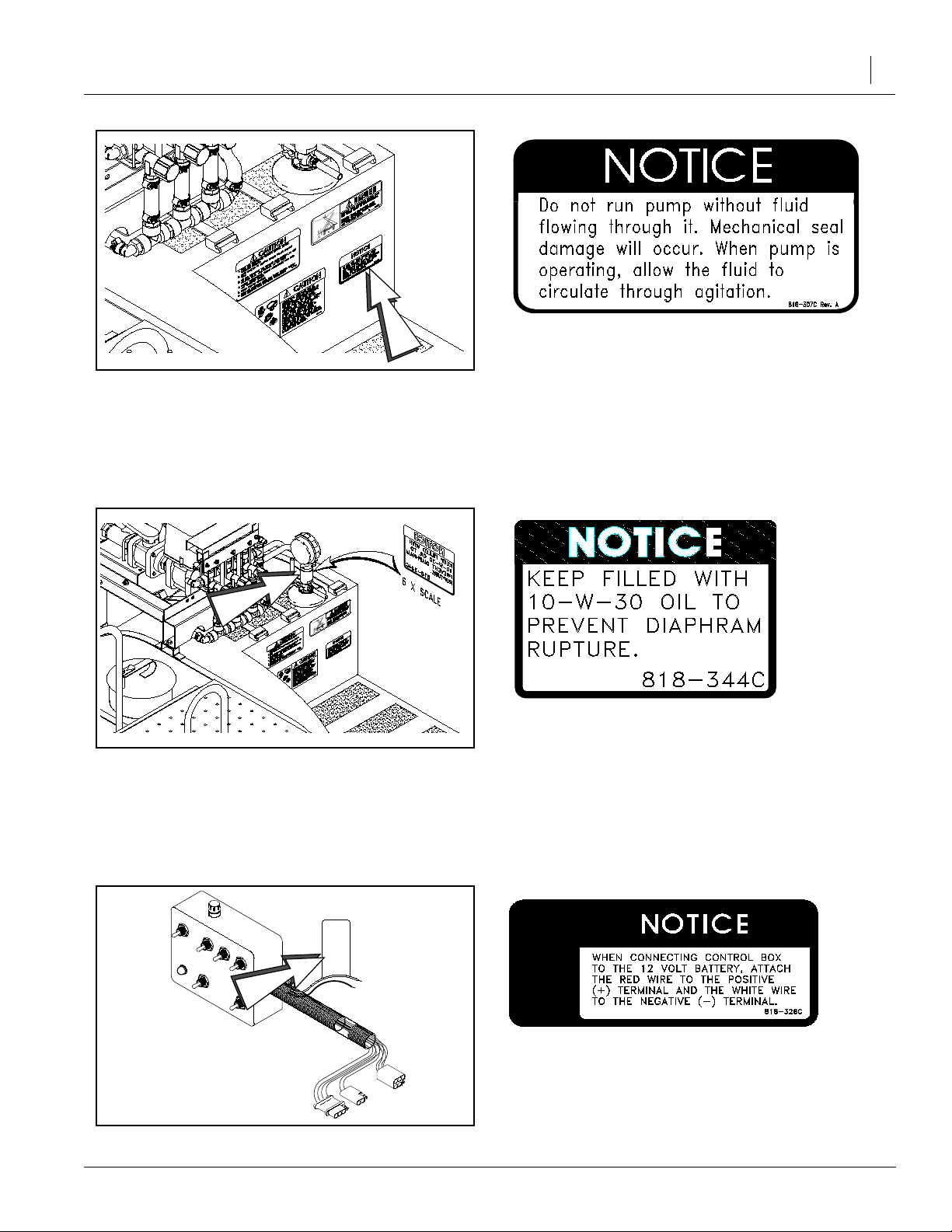
12538
12539
818-307C
Caution! Do Not run pump dry.
818-344C
Notice! Gauge protector.
5/13/2003
12540
818-326C
Notice! Control box power leads.
500-052M

Tractor Mount Sprayer
10
Introduction
GreatPlains welcomes youto its growingfamilyof
new product owners. This Tractor Mount Sprayer
has been designed with care and built by skilled
workers using quality materials. Proper setup,
maintenance and safe operating practices will
help you get years of satisfactory use from the
machine.
Intended Usage
Use this Tractor Mount Sprayeras part of a pressurized sprayer system to apply liquid pesticides,
herbicides or fertilizersto production-agriculture
crops only. Do not modify sprayer for use with attachments other than those approved by Great
Plains.
Models Covered
TM500 & TM700 Tractor Mount Sprayer
Using This Manual
This manual will familiarize you with safety, assembly, operation, adjustments, troubleshooting
and maintenance. Read this manual and follow
the recommendations to help ensure safe and efficient operation.
The information in this manual is current at printing. Some parts may change to assure top
performance.
Definitions
The followingterms are used throughout this
manual.
Right-hand and left-hand as used in this manual
are determined by facing the direction the machine will travel while in use unless otherwise
stated.
Owner Assistance
If you need customer service or repair parts, contact a Great Plains dealer. They have trained
personnel, repair parts and equipment specially
designed for Tractor Mount Sprayer products.
Your machine’sparts were specially designedand
should only be replaced with Tractor Mount Sprayer parts.Alwaysuse the serial and model number
whenordering partsfromyour GreatPlainsdealer.
Record your sprayer model and serial number
here for quick reference:
Model Number:__________________________
Serial Number: ___________________________
Your Great Plains dealer wants you tobe satisfied
with your new machine. If you do not understand
anypart of this manualorare not satisfied with the
service received, please take the following
actions.
1. Discussthe matter withyourdealershipservice
manager.Make sure they are aware of any
problems so they can assist you.
2. If you are still unsatisfied, seek out the owner
or general manager of the dealership.
3. For further assistance write to:
Product Support
Great Plains Mfg. Inc., Service Department
PO Box 5060
Salina, KS 67402-5060
500-052M
IMPORTANT: A crucial point of information related to the preceding topic. For safe and correct operation, read and follow the directions
provided before continuing.
NOTE: Useful information related to the preceding topic.
5/13/2003

Preparation and Setup
Preparation and Setup
11
Tractor Requirements
To operate your Great Plains Sprayer,a tractor using a
12 volt electrical system must be used.
The tractor will need two hydraulic outlets (one pair) if
the sprayer is equipped with a hydraulic pump.
Before You Start
Read and understand the owners manual for your
sprayer. A basic understanding of how the sprayer
works will aid in the assembly, setup and operation of
your sprayer.
Before attempting to assemble the sprayer, use the following as a checklist. Having all the needed parts and
equipment readily at hand will speed up your assembly
task and will make the job as safe as possible.
1.❑Check for all sprayercomponents and hardware.
2.❑Ifa bolt, pin or othercomponent has been removed,
or if you are unsure about where it is used, refer to the
parts manual to identify it.
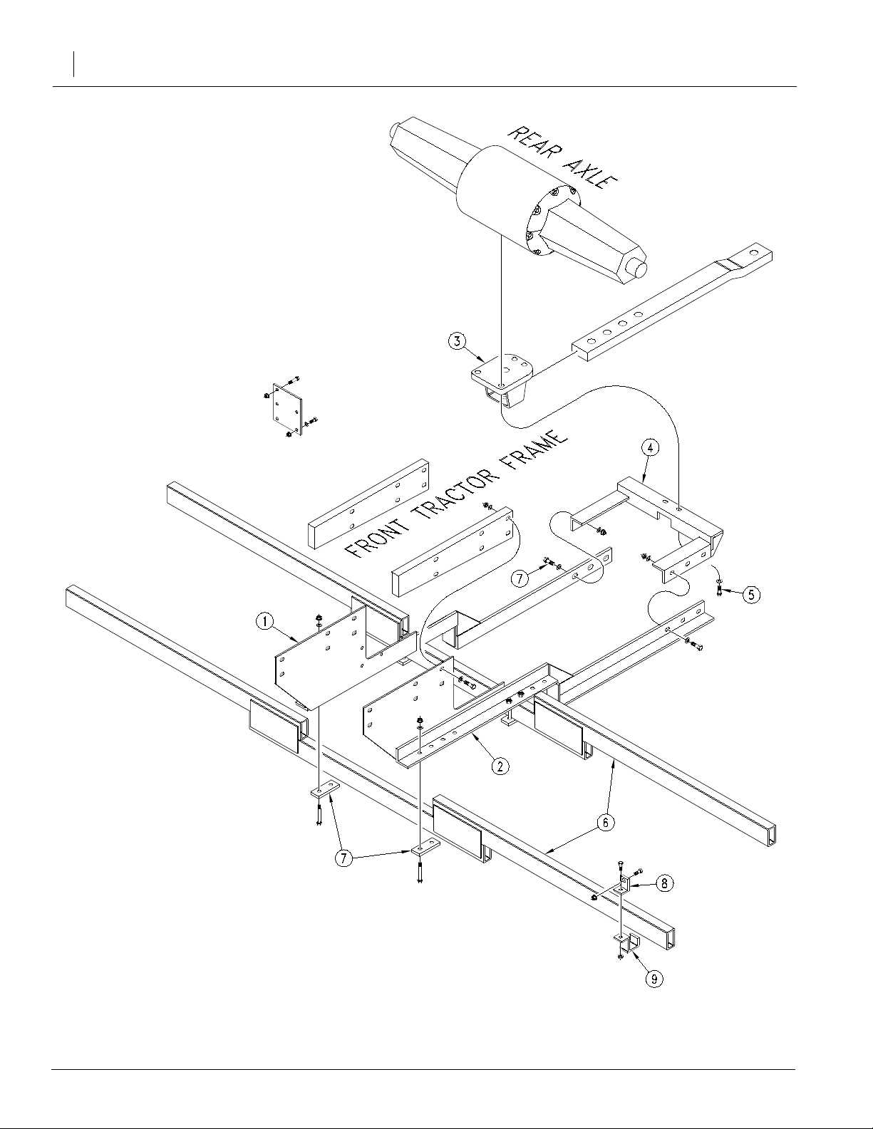
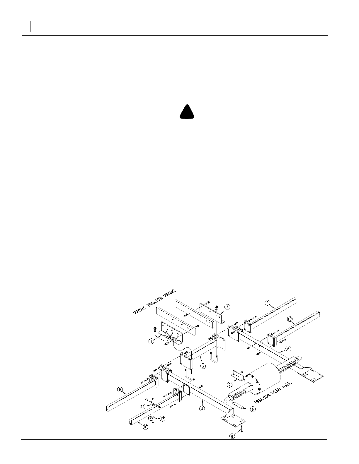
Case/IH 7110 - 7150 Tractor Mount
Assembly Instructions
Refer to Figure 2 on page 12
To assemble the side-mount tanks, you will need to remove the steps, the front fenders (if equipped) and
possibly other components to fit the tanks onto the
tractor.
1. Assemble the right (1) and left (2) side plates onto
the front of the tractor frame using the twelve 5/8" x
5" long bolts, flat washers and flange nuts.
whenyoufasten the railsonthatyoubolt them in the
same perspective hole locations or else the tanks
won’t fit on the rails.
6. Positionthe notched tank on the left railsandthe full
tank on the right rails with the tank caps toward the
outside.
!
WARNING
Lifting Hazard
-Use a crane or hoist to lift and position the tanks.
-The tanks can fall causing potential injury if not handled cor-
rectly.
Move the tanks so that there is sufficient clearance between the tanks and the tractor.
Refer to Figure 1
7. Assemble the angles (8) onto the outer holes in the
tank saddles using the 3/4" x 1 3/4" long bolts, and
flange nuts. There are four angles on each saddle
that support the four corners of the saddle.
8. Hook the four angle brackets(9) onto the rails for
each tank and bolt them to the angles (8) using the
1/2"x13/4" long bolts,andflange nuts.Releasethe
overheadsupport of the tanks after they are securely fastened.
9. Check and make sure allnutsare torqued to the correct specs listed in the “Torque Values Table”on
page 58.
10. Proceed with the “Plumbing & Controls Instruc-
tions” on page 15.
2. Remove the two front bolts from the tractor drawbar
support (3).
3. Assemble the rear bracket support (4) with the two
longer M16.2.0x75 metric bolts (5) and 5/8" flat
washers included.
4. Bolt together the right (1) and left (2) side plates to
therear bracketsupport(4) withthesix5/8" x 2"long
bolts, flat washers and flange nuts.
5. Assemble the two tank rails (6) onto the right (1) and
left (2) side plates with the backup plates (7), 5/8" x
6" long bolts, flat washers, and flange nuts. There
arethreelocationsto bolt these rails. Makesurethat
5/13/2003
12527
Figure 1
Angles on Saddle
500-052M
Tractor Mount Sprayer
12
500-052M
12526
Figure 2
Case/IH 7110 - 7150 Tractor Mount Assembly Instructions
5/13/2003
Preparation and Setup
13
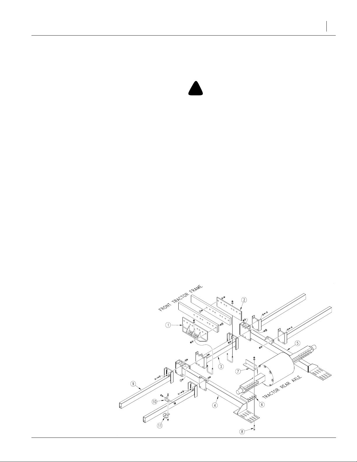
John Deere 4240 - 4455 Tractor
Mount Assembly Instructions
Refer to Figure 3
To assemble the side-mount tanks, you will need to remove the steps, the front fenders (if equipped) and
possibly other components to fit the tanks onto the
tractor.
1. Assemble the left (1) and right (2) side plates onto
thefront of the tractor frame using theeight 5/8" x 2"
long carriage bolts, flat washers and flange nuts.
2. Mount the spreader bar (3) onto the left and right
side plates with the u-bolts, 5/8" flange nuts, and
washers but do not tighten the nuts completely.
3. Determinewheretheleft (4) right (5)siderails will be
positioned so that when the tanks are mounted,
there will be sufficient clearance between the tires
andthetanks. Youwill havetoslide the spreader bar
(3) to position where the rails will be.
4. Fasten the left (4) and right (5) side rails to the
spreader bar (3) with four 5/8" x 2" long carriage
bolts, flat washers, and flange nuts on each rail.
Support the rear of the rails by assembling a few of
the bolts in step 5.
5. After determining where the left and right rails (4 &
5) will be positioned, use the optimum holes in the
rear portion of the rails (4 & 5) with the two spacer
blocks (6), four backup angles (7), eight 5/8" x 11
1/2"longbolts(8), and the eight 5/8" flange nuts and
washers.
7. Assemble the four tank rails (9) using the 5/8" x 2"
long bolts, flat washers and flange nuts.
8. Position the notched tank on the left railsandthe full
tank on the right rails with the tank caps toward the
outside.
!
WARNING
Lifting Hazard
-Use a crane or hoist to lift and position the tanks.
-The tanks can fall causing potential injury if not handled cor-
rectly.
Move the tanks so that there is sufficient clearance between the tanks and the tractor.
9. Assemble the angles (10) onto the outer holes in the
tanksaddles(referto Figure 1 on page 11) using the
3/4" x 1 3/4" long bolts, and flange nuts. There are
fourangles oneach saddle that supportthe fourcorners of the saddle.
10. Hook the four angle brackets (11) onto the rails for
eachtank and bolt them tothe angles (10) using the
1/2"x13/4" long bolts,andflange nuts.Releasethe
overheadsupport of the tanks after they are securely fastened.
11. Checkand makesure allnutsare torqued to the correct specs listed in the “TorqueValues Table”on
page 58
12. Proceed with the “Plumbing & Controls Instruc-
tions” on page 15.
6. Tighten all the hardware on all the components assembled to the correct torque specifications listed
on page 58.
Figure 3
John Deere 4240 - 4455 TractorMount
Assembly Instructions
5/13/2003
12528
500-052M
Tractor Mount Sprayer
14
John Deere 4630 - 4960 Tractor
Mount Assembly Instructions
Refer to Figure 4
To assemble the side-mount tanks, you will need to remove the steps, the front fenders (if equipped) and
possibly other components to fit the tanks onto the
tractor.
1. Assemble the left (1) and right (2) side plates onto
thefront of the tractor frame using theeight 5/8" x 2"
long carriage bolts, flat washers and flange nuts.
2. Mount the spreader bar (3) onto the left and right
side plates with the u-bolts, 5/8" flange nuts, and
washers but do not tighten the nuts completely.
3. Determinewheretheleft (4) right (5)siderails will be
positioned so that when the tanks are mounted,
there will be sufficient clearance between the tires
andthetanks. Youwill haveto slide the spreader bar
(3) to position where the rails will be.
4. Fasten the left (4) and right (5) side rails to the
spreader bar (3) with four 5/8" x 2" long carriage
bolts, flat washers, and flange nuts on each rail.
Support the rear of the rails by assembling a few of
the bolts in step 5.
5. After determining where the left and right rails (4 &
5) will be positioned, use the optimum holes in the
rear portion of the rails (4 & 5) with the two spacer
blocks(6), four backupangles(7),andtheeight 5/8"
x 10" long bolts (8), flange nuts and washers.
6. Tighten all the hardware on all the components assembled to the correct torque specifications listed
on page 56.
7. Assemble the front two tank rails (9) using the eight
5/8" x 2" long bolts, flat washers and flange nuts.
8. Assemble the rear to tank rails (10) using the four
5/8" x 5" bolts, four 5/8" x 2" long bolts and the eight
5/8" flange nuts and flat washers.
9. Positionthe notched tank on the left railsandthe full
tank on the right rails with the tank caps toward the
outside.
!
WARNING
Lifting Hazard
-Use a crane or hoist to lift and position the tanks.
-The tanks can fall causing potential injury if not handled cor-
rectly.
Move the tanks so that there is sufficient clearance between the tanks and the tractor.
10. Assemblethe angles (11) onto the outer holes in the
tanksaddles(referto Figure 1 on page 11) using the
3/4 x 1 3/4" long bolts, and flange nuts. There are
fourangles oneach saddle that supportthe fourcorners of the saddle.
11. Hook the four angle brackets (12) onto the rails for
eachtank and bolt them tothe angles (11) using the
1/2"x13/4"long bolts,andflange nuts.Releasethe
overheadsupport of the tanks after they are securely fastened.
12. Checkand makesure allnutsare torqued to the correct specs listed in the “Torque Values Table”on
page 58.
13. Proceed with the “Plumbing & Controls Instruc-
tions” on page 15.
Figure 4
John Deere 4630 - 4960 Tractor
Mount Assembly Instructions
500-052M
12529
5/13/2003
Preparation and Setup
15
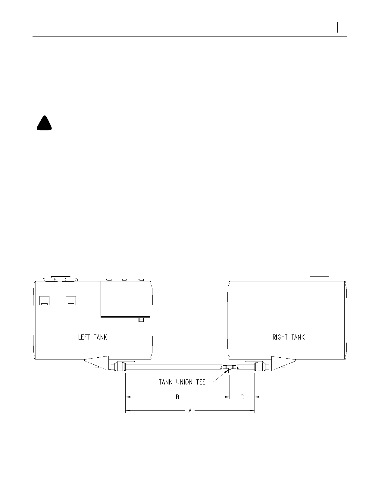
Plumbing & Controls Instructions
Refer to Figure 5
1. Measure the distance “A” to determine where the
tank union tee should be placed.
2. The length “B” and length “C” should be as follows:
Length “B” 75% of Length “A”
Length “C” 25%of Length “A”
!
CAUTION
Chemical Hazard
Make sure the tank union tee is assembled according to instructions. Failure to place the tee in the correct position may
cause water overflow out of a tank when filling the tanks.
Chemical residue previously in the tank could be exposed to
the environment if the fill-water is spilled.
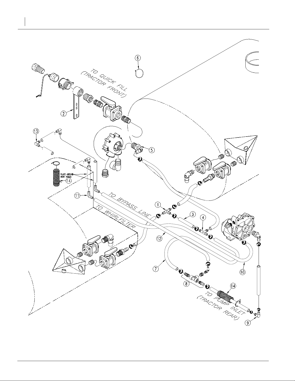
Refer to Figure 6 on page 16
3. Assemble the 1 1/2" hose barb tank union tee (1)
withthecorrectlengthof11/2" ID hose according to
the measurements you determined in step 2. It is
recommended to use petroleum jelly or some type
oflubricant in the insidediameter of the hose before
it is assembled on the hose barbs. It will make the
assembly much easier. Tighten the #28 hose
clamps after the hose is assembled.
4. Mount the quick-fill bracket (2) on the front of your
tractorso that the fill-coupler is easilyaccessed.You
may be able to place the quick-fill bracket in-between two tractor weights.
5. Cut a short section of 1 1/2" hose (3) and assemble
a second 1 1/2" hose barb tee (4) on the section of
hose. Fasten the hose with the #28 hose clamps
when finished.
6. Measure out and cut a section of 1 1/2"IDhosefrom
thetee(4)tothe hose barb (5). Secure the #28 hose
clamps when finished. Use plastic cable-ties 6) to
secure the hose to the tractor. Make sure the hose
does not droop below the tractor where it could get
caught.
7. Attach another short section of 1 1/2" ID hose (7) in
between tee (4) and the tee assembly (8). Tighten
the #28 hose clamps.
8. Follow the “Tractor/PTO Pump Hook-Up”on
page 20 {if equipped} and mount the pump onto the
tractor.
9. Measure and assemble a section of 1 1/2" ID hose
from the tee assembly (8) to the pump with a 1 1/2"
hose barb elbow (9) just below the pump. The sectionof hose in-between the hose barb elbow (9) and
the pump should be less than a foot long. Tighten
the #28 hose clamps.
10. Use cable ties (6) to secure the hose under the tractor.
Figure 5
Tank Union Tee
12545
5/13/2003
500-052M
Tractor Mount Sprayer
16
500-052M
12534
Figure 6
Plumbing Assembly Instructions
5/13/2003
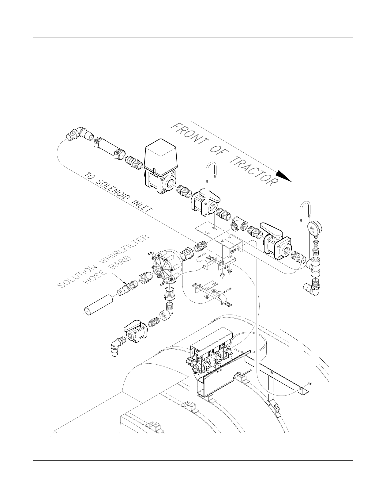
Refer to Figure 7
11. Cuta 1"IDhose(10)thatleadsfromthe pump to
the solution Whirlfilter®hose barb. You will need
to place 1" elbow hose-barbs (11) as shown to
orient the hose up the side of the tank. Measure
out and cut a length of hose guard material (14)
along the area between the tractor and the tank,
and route hose from pump to Whirlfilter®hose
Preparation and Setup
barb through the hose guard material. Pump
suctionand pressure line should also berouted
through the hose guard material where sharp
corners exist under the tractor transmission area. Tighten the #16 hose clamps.
12. Use cable ties (6) to secure the hose under the
tractor.
17
5/13/2003
13229
Figure 7
Pressure Head Assembly
500-052M
 Loading...