

Great Plains TCN5313 User Manual
Table of Contents Index
Assembly Manual
5107, 5309, 5311 & 5313
Turbo-Chisel TCN
Manufacturing, Inc.
www.greatplainsmfg.com
Read the operator’s manual entirely. When you see this symbol, the
subsequent instructions and warnings are serious - follow without
exception. Your life and the lives of others depend on it!
Illustrations may show optional equipment not supplied with standard unit.
41967
ORIGINAL INSTRUCTIONS
© Copyright 2014 Printed 2014-03-17 566-170Q-ENG
Table of Contents Index
EN

Table of Contents Index
Table of Contents Index

Great Plains Manufacturing, Inc. iii
Table of Contents
Important Safety Information ..................................... 1
Introduction ..................................................................4
Description of Unit ..........................................................4
Models Covered ............................................................. 4
Document Family ...........................................................4
Tools Required ...............................................................4
Pre-assembly Checklist..................................................4
Using This Manual..........................................................5
Definitions................................................................... 5
Shipping Inventory..........................................................6
Unloading ....................................................................... 6
Unpacking Components .............................................6
Unload Smaller Items First .........................................6
Unpacking Boxes .......................................................6
Assembly and Setup Assistance ................................6
Assembly ......................................................................7
Torque Tube...............................................................7
Center Lift & Gang Mount........................................... 7
Trusses....................................................................... 8
Hitch & Center Lift Assembly...................................... 8
Wings .......................................................................10
569-190S Shank....................................................... 12
569-196S Shank....................................................... 12
Turbo Gang ..............................................................13
Depth Gauge ............................................................13
Valve, Fitting and Hose Assembly................................14
Depth Stop ...............................................................14
Install Rebound Valve and O-Ring Fittings...............14
Install Hose Handle and JIC Fittings ........................15
Attach Hose Clamps and Hose wraps...................... 16
Hydraulic Hose Hookup............................................ 16
Hose Handles........................................................... 17
Purging Hydraulic System........................................17
North American Light Assembly...............................18
International Lights Assembly .................................. 20
Air Brakes Assembly ................................................ 22
Hydraulic Brakes Assembly ..................................... 24
Install Rear Hitch (optional)......................................26
Completing Setup..................................................... 26
Appendix..................................................................... 27
Torque Values Chart.................................................... 27
Tire Inflation Chart ....................................................... 28
Hydraulic Connectors and Torque ............................... 28
Hydraulic Lift Layout .................................................... 29
3-Section Hydraulic Fold Layout .................................. 30
5107 Hydraulic Gang Layout ....................................... 31
5309-5313 Hydraulic Gang Layout .............................. 32
TCN 5107 Machine Layout .......................................... 33
TCN5309 Machine Layout ........................................... 34
TCN5311 Machine Layout ........................................... 35
TCN5313 Machine Layout ........................................... 36
Twisted Shovel Layout................................................. 37
TCN5107 Chopper Reel Layout................................... 38
TCN5309 Chopper Reel Layout................................... 39
TCN5311 Chopper Reel Layout................................... 40
TCN5313 Chopper Reel Layout................................... 41
TCN 5107 Buster Bar Layout....................................... 42
TCN5309 Buster Bar Layout........................................ 43
TCN5311 Buster Bar Layout........................................ 44
TCN5313 Buster Bar Layout........................................ 45
Index............................................................................ 47
© Copyright 2006, 2007, 2008, 2009, 2010, 2011, 2012, 2013, 2014 All rights Reserved
Great Plains Manufacturing, Inc. provides this publication “as is” without warranty of any kind, either expressed or implied. While every precaution has been
taken in the preparation of this manual, Great Plains Manufacturing, Inc. assumes no responsibility for errors or omissions. Neither is any liability assumed for
damages resulting from the use of the information contained herein. Great Plains Manufacturing, Inc. reserves the right to revise and improve its products as
it sees fit. This publication describes the state of this product at the time of its publication, and may not reflect the product in the future.
03/17/2014 566-170Q-ENG
Trademarks of Great Plains Manufacturing, Inc. include: Singulator Plus, Swath Command, Terra-Tine.
Registered Trademarks of Great Plains Manufacturing, Inc. include:
Air-Pro, Clear-Shot, Discovator, Great Plains, Land Pride, MeterCone, Nutri-Pro, Seed-Lok, Solid Stand,
Terra-Guard, Turbo-Chisel, Turbo-Chopper, Turbo Max, Turbo-Till, Ultra-Till, Verti-Till, Whirlfilter, Yield-Pro.
Brand and Product Names that appear and are owned by others are trademarks of their respective owners.
Printed in the United States of America

iv TCN5107-5313 Great Plains Manufacturing, Inc.
566-170Q-ENG 03/17/2014
Great Plains Manufacturing, Inc. 1
Important Safety Information
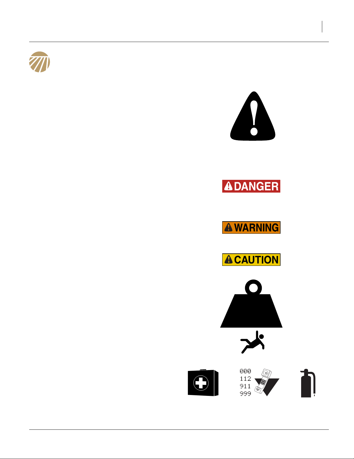
Look for Safety Symbol
The SAFETY ALERT SYMBOL indicates there is a
potential hazard to personal safety involved and extra
safety precaution must be taken. When you see this
symbol, be alert and carefully read the message that follows it. In addition to design and configuration of equipment, hazard control and accident prevention are
dependent upon the awareness, concern, prudence and
proper training of personnel involved in the operation,
transport, maintenance and storage of equipment.
Be Aware of Signal Words
Signal words designate a degree or level of hazard seriousness.
DANGER indicates an imminently hazardous situation
which, if not avoided, will result in death or serious injury.
This signal word is limited to the most extreme situations,
typically for machine components that, for functional purposes, cannot be guarded.
WARNING indicates a potentially hazardous situation
which, if not avoided, could result in death or serious
injury, and includes hazards that are exposed when
guards are removed. It may also be used to alert against
unsafe practices.
CAUTION indicates a potentially hazardous situation
which, if not avoided, may result in minor or moderate
injury. It may also be used to alert against unsafe practices.
Use Adequate Lifting Means
The frame sections and gangs of this machine are
extremely heavy. If using multiple lifters, make sure each
is rated for at least its share of the load.
> 14,000
POUNDS
Prepare for Emergencies
▲ Be prepared if a fire starts
▲ Keep a first aid kit and fire extinguisher handy.
▲ Keep emergency numbers for doctor, ambulance, hospital
and fire department near phone.
03/17/2014 566-170Q-ENG
2 TCN5107-5313 Great Plains Manufacturing, Inc.
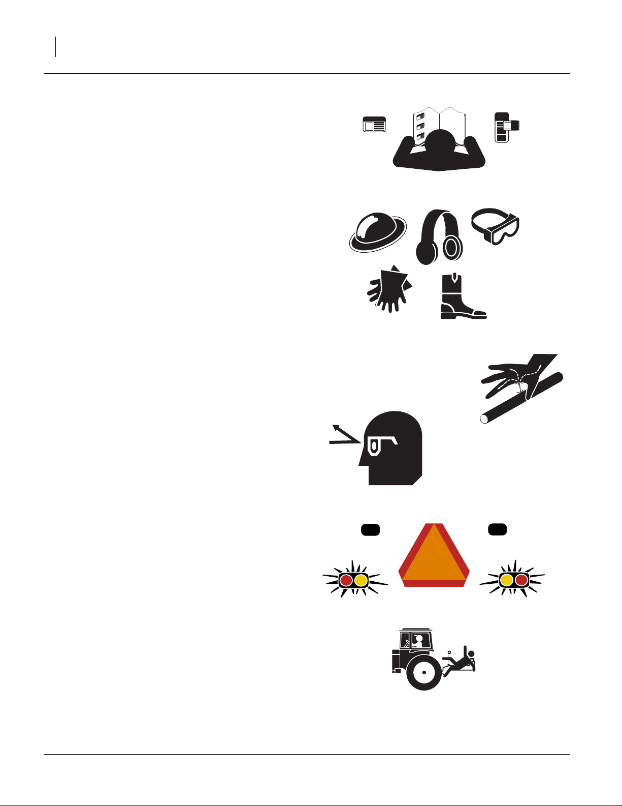
Be Familiar with Safety Decals
▲ Read and understand the “Safety Decals” section of the
Operators Manual.
▲ Read all instructions noted on the decals.
▲ Keep decals clean. Replace damaged, faded and illegible
decals.
Wear Protective Equipment
▲ Wear protective clothing and equipment.
▲ Wear clothing and equipment appropriate for the job. Avoid
loose-fitting clothing.
▲ Because prolonged exposure to loud noise can cause hear-
ing impairment or hearing loss, wear suitable hearing protection such as earmuffs or earplugs.
▲ Because operating equipment safely requires your full
attention, avoid wearing entertainment headphones while
operating machinery.
Avoid High Pressure Fluids
Escaping fluid under pressure can penetrate the skin,
causing serious injury.
▲ Avoid the hazard by relieving pressure before disconnecting
hydraulic lines.
▲ Use a piece of paper or cardboard, NOT BODY PARTS, to
check for suspected leaks.
▲ Wear protective gloves and safety glasses or goggles when
working with hydraulic systems.
▲ If an accident occurs, seek immediate medical assistance
from a physician familiar with this type of injury.
Use Safety Lights and Devices
Slow-moving tractors and towed implements can create
a hazard when driven on public roads. They are difficult
to see, especially at night.
▲ Use flashing warning lights and turn signals whenever driv-
ing on public roads.
Use lights and devices provided with implement
Keep Riders Off Machinery
Riders obstruct the operator’s view. Riders could be
struck by foreign objects or thrown from the machine.
▲ Never allow children to operate equipment.
▲ Keep all bystanders away from machine during operation.
566-170Q-ENG 03/17/2014
Great Plains Manufacturing, Inc. Important Safety Information 3
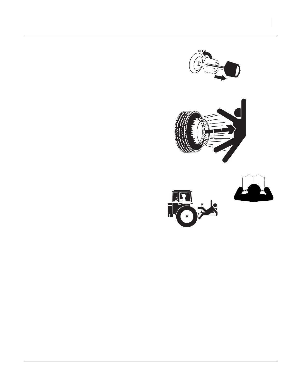
Shutdown and Storage
▲ Lower implement, put tractor in park, turn off engine, and
remove the key.
▲ Secure Turbo-Chisel using blocks and supports provided.
▲ Detach and store Turbo-Chisel in an area where children
normally do not play.
Tire Safety
Tire changing can be dangerous and should be performed by trained personnel using correct tools and
equipment.
▲ When inflating tires, use a clip-on chuck and extension hose
long enough for you to stand to one side–not in front of or
over tire assembly. Use a safety cage if available.
▲ When removing and installing wheels, use wheel-handling
equipment adequate for weight involved.
Safety At All Times
Thoroughly read and understand the instructions in this
manual before operation. Read all instructions noted on
the safety decals.
▲ Be familiar with all machine functions.
▲ Operate machinery from the driver’s seat only.
▲ Do not leave machine unattended with tractor engine run-
ning.
▲ Do not stand between the tractor and machine during
hitching.
▲ Keep hands, feet and clothing away from power-driven
parts.
▲ Wear snug-fitting clothing to avoid entanglement with mov-
ing parts.
▲ Watch out for wires, trees, etc., when folding and raising
machine. Make sure all persons are clear of working area.
03/17/2014 566-170Q-ENG
4 TCN5107-5313 Great Plains Manufacturing, Inc.
Introduction
The Turbo-Chisel TCN has been designed with care and
built by skilled workers using quality materials. Proper
setup, maintenance, and safe operating practices will help
the customer get years of satisfactory use from the
machine.
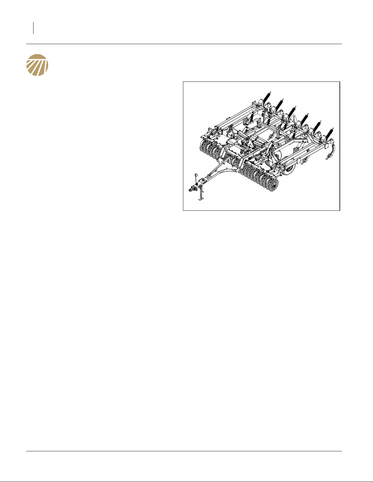
Description of Unit
The TCN5107-5313 Turbo-Chisel is a one or three-section
“vertical” tillage tool. Working width ranges from 9 to 17
feet. The implement is designed to cut, size and bury residue. It can work up to 11” deep, will dislodge rootballs and
leave the field smooth enough for “one pass” finishing in
Spring. For optimum leveling of your machine, it should be
equipped with either a Chopper Reel or Buster Bar attachment.
Models Covered
TCN5107 15-Foot 1-section
TCN5309 18-Foot 3-section
TCN5311 21-Foot 3-section
TCN5313 24-Foot 3-section
Document Family
566-170Q-ENG Assembly Manual (this document)
566-170Q Pre-Delivery Manual
566-170M Operator Manual
566-170P Parts Manual
Tools Required
• Basic Hand Tools
• Torque Wrench
• Fork Truck, Overhead Hoist or Loader
Pre-assembly Checklist
1. Before assembling, read and understand “Important
Safety Information” in front part of this manual.
2. Have at least two people on hand while assembling.
Figure 1
Turbo-Chisel
3. Make sure area is level and free of obstructions
(preferably an open concrete area).
4. Have all major componets
5. Have all fasteners and pins shipped with Discovator.
41977
566-170Q-ENG 03/17/2014
Great Plains Manufacturing, Inc. Introduction 5
Using This Manual
This manual was written to help you assemble and prepare the new machine for the customer. The manual
includes instructions for assembly and setup. Read this
manual and follow the recommendations for safe, efficient and proper assembly and setup.
An operator’s and parts manual is also provided with the
new machine. Read and understand “Important Safety
Information” and “Operating Instructions” in the operator’s manual before assembling the machine. Refer to
the parts manual for proper part’s identification. As a reference, keep the operator’s and part’s manual on hand
while assembling.
The information in this manual is current at printing.
Some parts may change to assure top performance.
Definitions
The following terms are used throughout this manual.
A crucial point of information related to the preceding topic.
Read and follow the directions to remain safe, avoid serious
damage to equipment and ensure desired field results.
Note: Useful information related to the preceding topic.
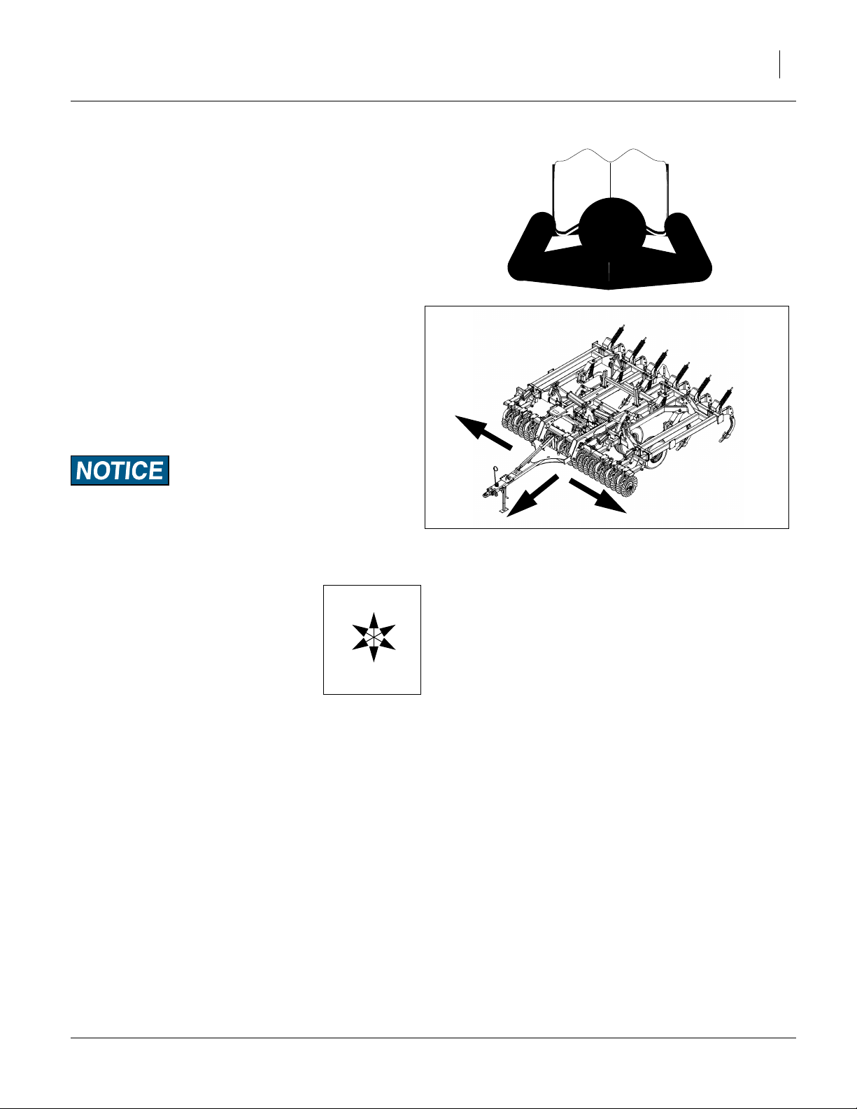
Right-hand and left-hand as used in
this manual are determined by facing
the direction the machine will travel
while in use unless otherwise stated.
An orientation rose in some line art
illustrations shows the directions of: Up,
Back, Left, Down, Front, Right.
R
F
U
B
L
D
R
L
Figure 2
Right / Left
41977
03/17/2014 566-170Q-ENG
6 TCN5107-5313 Great Plains Manufacturing, Inc.
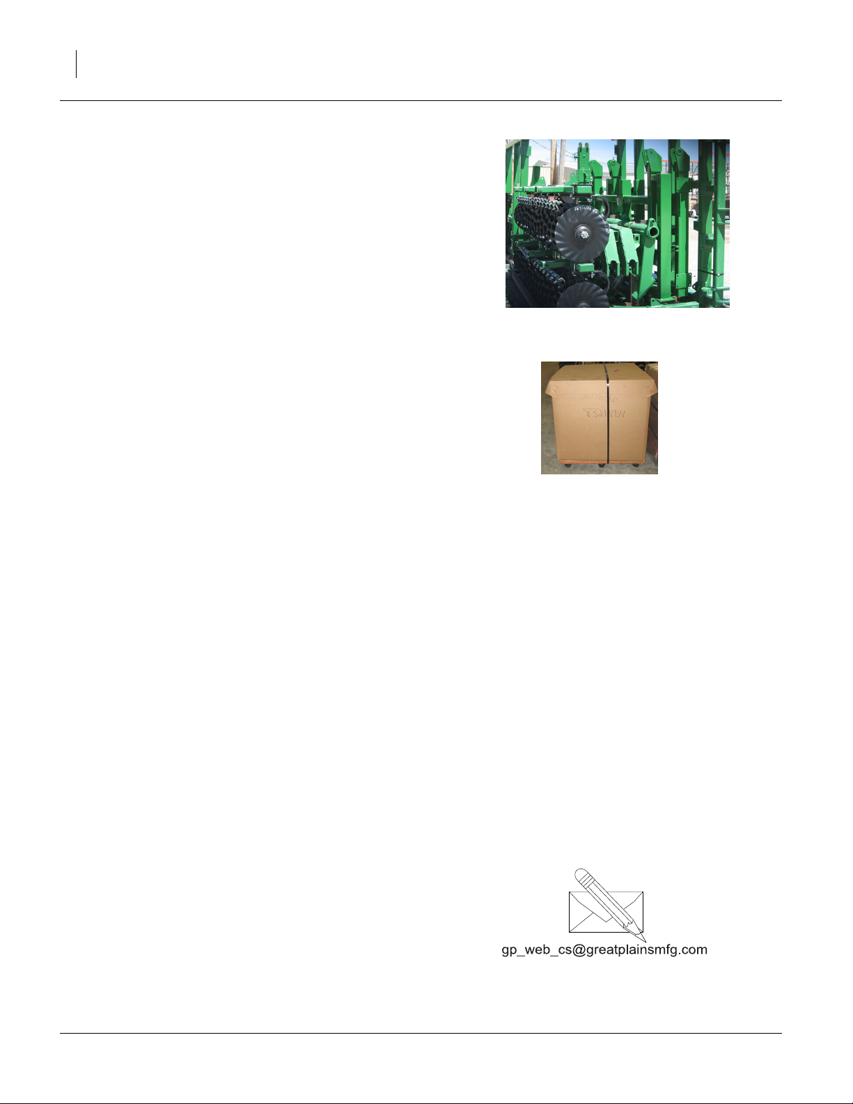
Shipping Inventory
The Turbo-Chisel will be shipped unassembled as
shown in a big shipping rack and shipping boxes on pallets. The only parts that will be assembled are the turbo
gang assemblies and reel attachment assemblies. The
reel attachments (if equipped) will be banded together
with the gang assemblies on pallet.
Refer to Figure 3
• All frame sections, hitch and torque tubes will be
shipped in shipping container.
41356
Refer to Figure 4
• Shank parts (mount assembly and shank assembly),
small parts and bolts will be shipped in boxes. Rear
attachment big parts will be banded to attachment
smaller parts box.
Shipping containers do not need to be returned to Great
Plains.
Figure 3
Shipping Rack
Unloading
Once everything is unloaded from “storage pod” you may
proceed with taking parts out of shipping containers.
Carefully move everything to level site and prepare to un
pack items.storage
Unpacking Components
Be sure you have read and understood the Important
Safety Information, starting on page 1 of this manual,
before you start unpacking componets.
Centering componets:
Be sure and center fork truck or chains (overhead hoist)
on componets so they won’t slide and cause injury.
Carefully un-band componets.
Now unload individual componets one at a time using a
fork truck or overhead hoist.
Move each component out of the way so you have plenty
of room to remove the next one.
Unload Smaller Items First
Unloading the frames is a potentially dangerous operation.
Reduce risk and complication by first unloading
6. the tire wheel assemblies,
7. the smaller items
Place these components well out of the manoeuvring
area needed for unloading the gang assemblies and
frames.
Figure 4
Shipping Boxes
8. Carefully unload the Frames and hitch out of shipping rack
41621
Unpacking Boxes
9. Carefully remove banding and lids from boxes.
10. Locate and identify all componets before assembling.
Assembly and Setup Assistance
To order additional copies od pre-delivery instructions or
operator.s and parts manuals, write to the following
address. Include model numbers in all correspondence.
If you do not understand any part of this manual or have
the assembly or setup questions, assistance is available.
Contact:
Product Support
Great Plains Mfg. Inc., Service Department
PO Box 5060
Salina, KS 67402-5060
(800)255-9215
566-170Q-ENG 03/17/2014
Great Plains Manufacturing, Inc. 7
Assembly
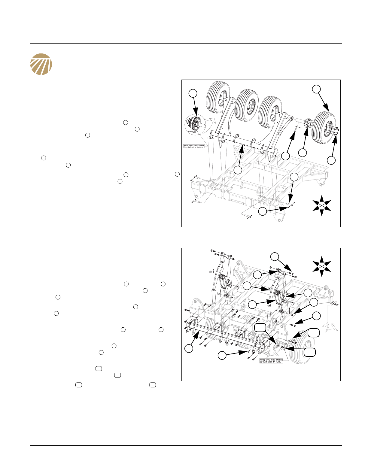
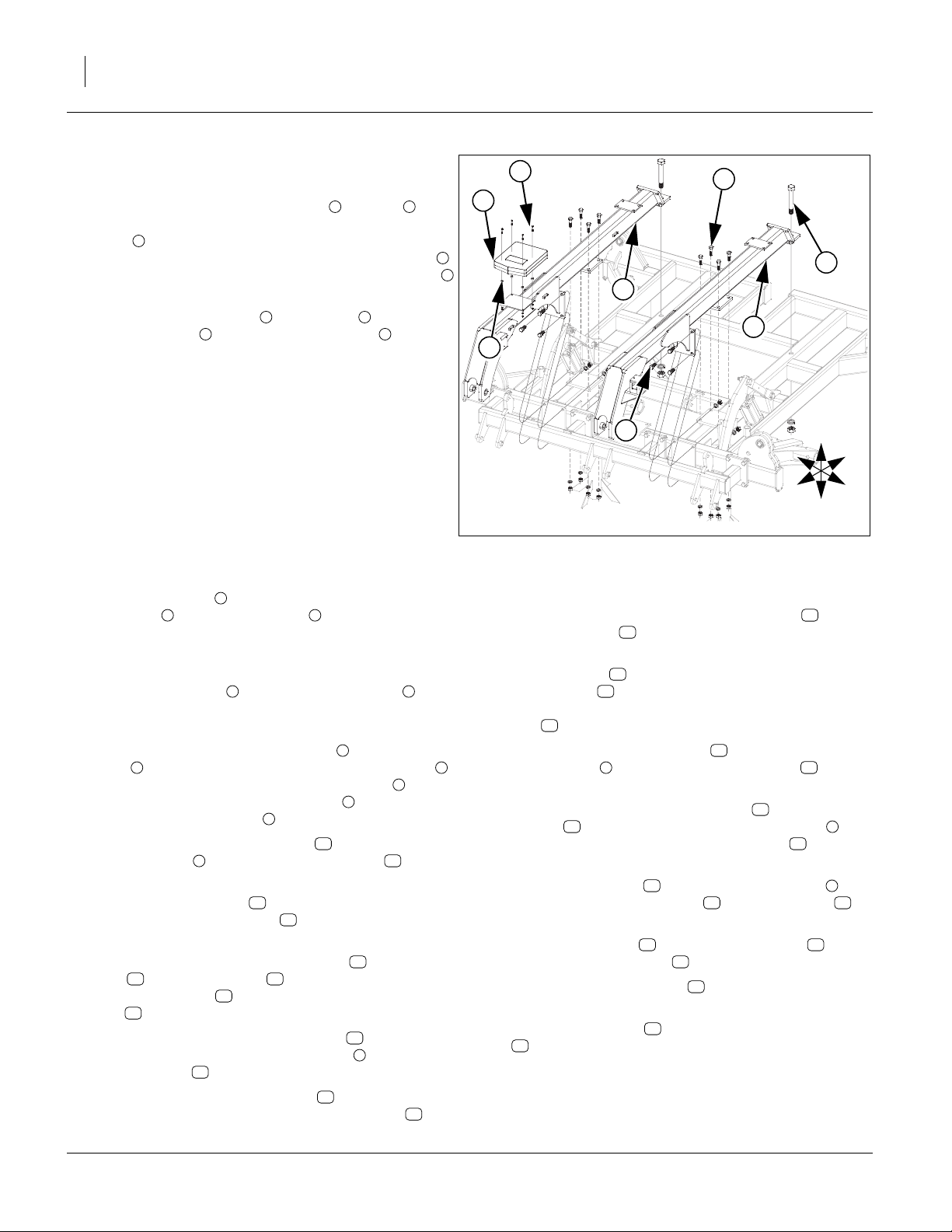
Torque Tube
Refer to Figure 5
11. Once the center Frame has been uncrated, carefully
turn the center frame upside down and set on blocks
to assemble torque tube.
12. Carefully raise the torque tube with an overhead
hoist and secure with 1 1/4 x 7 pins , 3/8 x 2 1/4 Gr.
8 special thread and 3/8 top lock nut.
13. Install pre-assembled hub assembly or brake hub
(LH and RH, on outside spindle locations) assembly
4
(if machine is equipped with brakes) using the 1 x
4 5/8 pin and secure with 3/8 x 2 roll pin.
14. Attach the tire/wheel assembly to hub assembly
and secure with 5/8 lug nuts .
15. All bolts may be tightened to specs, See “Torque
Values Chart” on page 27.
5
3
1
2
6
7
4
5
4
1
2
6
4
7
U
R
B
Center Lift & Gang Mount
Refer to Figure 6
16. Carefully raise center frame up from front bar and
turn over and set on stands.
17. Attach the cylinder mount bars and lift link to
center frame using 1 x 3 1/2 hex bolts , 1 x 4 hex
bolts and lock nuts.
4
18. Now install 4 x 10 x 1.38 cylinders using 1 x 3 1/8
pins , 1.5 x 1.0 x.075 machine washers and 3/16 x
6
2 cotter pins.
19. Install cylinder transport locks to cylinders using
the 5/16 wire retainer pin.
20. Attach center gang mount to front of center frame
with 3/4 x 2 hex bolts , 3/4 lock washers and 3/4
nuts.
Note: Store extra shims on back side of end plate fac-
ing down with same bolts that hold rest of shims.
21. Install shims with 3/8 x 1 1/4 hex bolts , 3/8 lock
washers and 3/8 nuts.
22. All bolts may be tightened to specs, See “Torque
Values Chart” on page 27.
10 11
9
10
1 2
3
5
7 5
8
11
3
F
L
D
Figure 5
Torque Tube
42006
U
3
2
R
F
B
L
D
1
7
5
6
4
11
10
8
9
Figure 6
Center Lift & Gang Mount
10
42007
03/17/2014 566-170Q-ENG
8 TCN5107-5313 Great Plains Manufacturing, Inc.
Trusses
Refer to Figure 7
23. Start by bolting the rear of the LH and RH
1 2
trusses to center frame using 1 1/4 x 8 1/2 Gr. 8 hex
bolts , 1 1/4 lock washers and 1 1/4 nuts. Attach
3
middle plates of trusses with 3/4 x 2 1/2 hex bolts ,
3/4 lock washers, 3/4 nuts, front plates with 3/4 x 2
4
5
3/4 lock washers, and 3/4 nuts.
24. Mount the manual pack to RH truss plate with 1/
4x1hexbolts , mini end press wheels , 1/4 lock
7 8
6 2
washers and 1/4 nuts.
25. All bolts may be tightened to specs, See “Torque
Values Chart” on page 27.
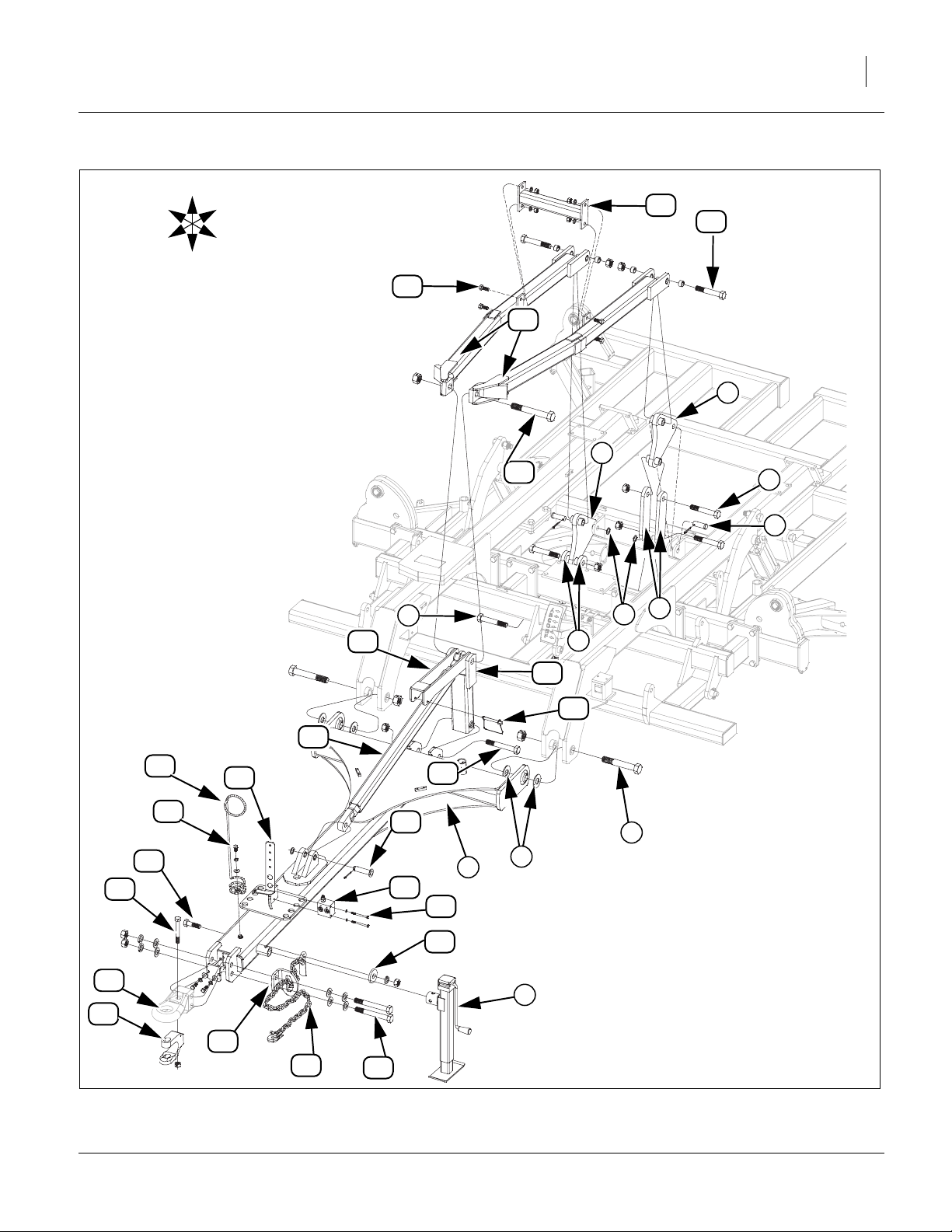
Hitch & Center Lift Assembly
Refer to Figure 8
26. Attach hitch pole to trusses using 1 1/4 x 8 Gr. 8
hex bolts , 1 1/4 flat washers (one on each side
2 3
of uni-ball) and top lock nuts. Washers are needed to
ensure a tight fit. Bolts need tightened securely, but
do not over-tighten as the hitch needs to pivot.
27. Mount square jack to front mount on hitch with
pin provided with jack. Use jack to help support front
of hitch for rest of hitch assembly.
28. Attach the four lift mechanism links to the level bar
links and torque tube with 1 x 6 Gr. 8 hex bolts ,
6 7
and 1 lock nuts. Attach rear of level bar link to center frame ears with 1 x 2 29/64 pins , 1.5 x 1.0
x.075 machine washers and 3/16 x 2 cotter pins.
29. Attach the rear of the level bars to the top of the
level bar links with 1 x 6 Gr. 8 hex bolts and 1
lock nuts.
30. Attach level bar brace between the level bars
using 5/8 x 1 1/2 hex bolts , 5/8 lock washers and
5/8 nuts.
31. Now the back of the hitch turnbuckle , turnbuckle
lock and leveling arm may be attached to the
15 16
front of level bars with 1 1/4 x 9 special thread hex
bolt and 1 1/4 lock nut.
17
32. The bottom of the hitch leveling arm can be
attached to the back of the hitch pole using 1 x 7
Gr. 8 hex bolt and 1 lock nut.
33. The front of the hitch turnbuckle may be attached
to the hitch pole ears with 1 x 3 5/8 clevis pin , 1.5
1
4 1
9
10
6
12
13
10
18
14
5
6
8
11
14
16
1
19
7
4
6
3
2
1
8
5
R
F
U
B
L
D
Figure 7
Truss
x 1.0 x.075 machine washers and 3/16 x 2 cotter
pins. Attach the 3/8 x 4 pin wire snap lock to the
turnbuckle lock .
15
34. If machine is equipped with optional brakes, install
air line holder , through first coil of spring in the
hose holder . Secure by aligning holes in hose
21
22
holder and hole on air line holder, install 1/2 x 1 hex
bolt ,1/2 flat washer, 1/2 lock washer and 1/2 nut.
23
35. Attach counterbalance valve to the plate on front
of hitch pole with 5/16 x 3 1/2 hex bolts and 5/
1
24
16 lock washers.
36. Align holes in safety chain support , cat III hitch
tongue with holes on left side of hitch pole ,
27
26
secure with 1 x 8 Gr. 8 special hex bolts , 1 lock
washers and 1 nut.
37. Install safety chain on bottom side of hitch ,
secure with 7/8 x 3 hex bolt , 7/8 flat washer , 7/
29
30 31
8 lock washer and 7/8 nut.
38. Attach hitch clevis to cat III hitch tongue with 3/
4 x 5 1/2 Gr. 8 hex bolt and 3/4 lock nut.
Note: Do not use hitch clevis if tractor has a hammer
32 27
33
32
strap. Use for transporting with truck.
39. Route safety chain through safety chain support
.
26
29
40. All bolts may be tightened to specs, See “Torque
Values Chart” on page 27.
42008
20
25
1
28
1
566-170Q-ENG 03/17/2014
Great Plains Manufacturing, Inc. Assembly 9
U
R
B
12
11
F
L
D
13
10
6
6
17
7
33
30
22
23
21
14
15
7
19
24
18
25
31
8
5
9
5
16
20
2
1
3
27
4
32
26
29
03/17/2014 566-170Q-ENG
28
Figure 8
Hitch & Center Lift
43364

10 TCN5107-5313 Great Plains Manufacturing, Inc.
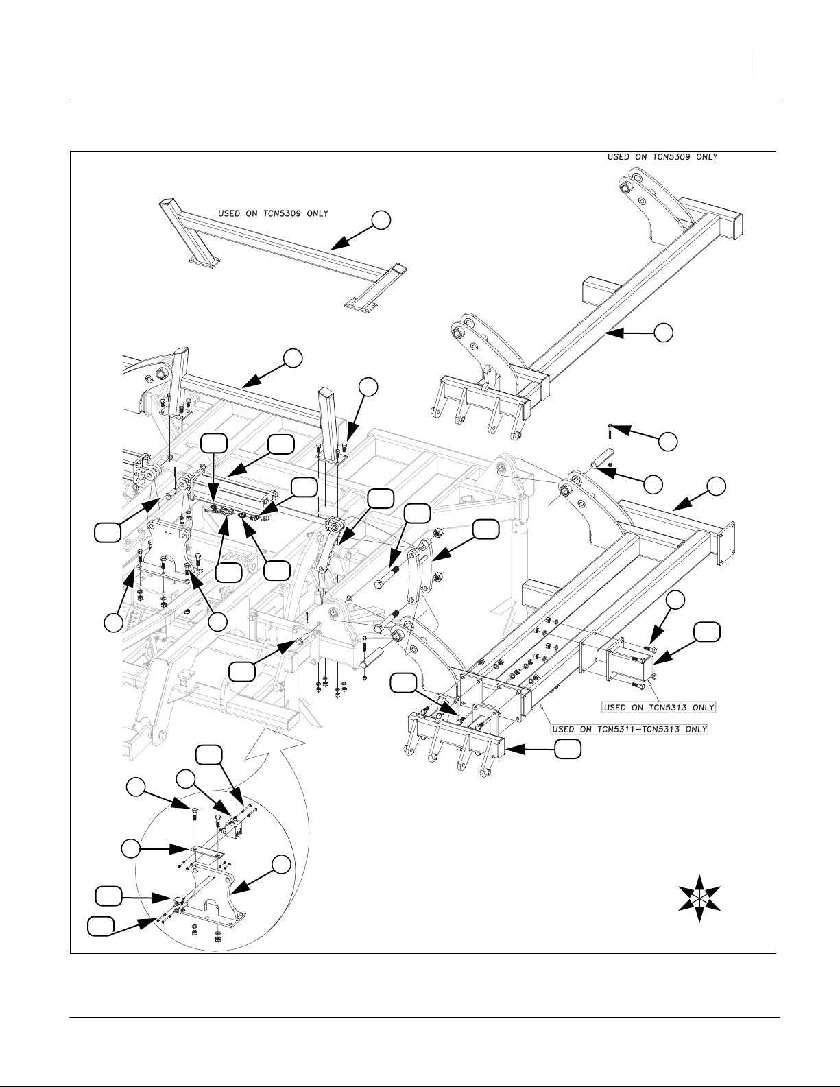
Refer to Figure 9
Wings
41. Carefully align holes in wing frame LH and RH
1
with holes on center frame hinges. Secure with 1 3/4
x 8 5/8 pins , 1/2 x 3 1/2 hex bolts and 1/2 top
2 3
lock nuts.
Note: Be sure hole in pin and hole in collar on wing
frame are aligned and bolt goes through both of
them.
42. Attach wing stop to center frame with 5/8 x 1 1/2
hex bolts , 5/8 lock washers and 5/8 nuts.
5
43. Install center fold bracket to center frame with 3/4
x 2 1/2 hex bolts , 3/4 lock washers and 3/4 nuts.
44. Attach rebound valve plate with 3/4 x 2 1/2 hex
bolts , 3/4 lock washers and 3/4 nuts.
7
45. Install rebound valve with 5/16 x 4 hex bolt 5/16
4
6
7
8
9
10
lock washer and 5/16 hex nut.
46. Attach double tee block with 5/16 x 3 1/2 hex bolts
, 5/16 lock washer and 5/16 hex nut.
12
47. Attach wing shank mount (model 5313 only),
secure with 3/4 x 2 1/2 hex bolts , 3/4 lock washers
11
13
7
and 3/4 nuts.
48. Align holes in link , rod end of 5 x 16 x 1.5 cylinder
and double fold link , secure with 1 1/4 x 9 spe-
15 16
cial thread hex bolts and 1 1/4 top lock nuts.
14
17
49. Secure other end of link to front wing hinge lower
hole with 1 1/4 x 3 5/8 pin , 1.88 x 1.25 x 10 ga
14
21
machine washer and 3/16 x 2 cotter pins.
50. Secure base end of cylinder with 1 x 3 1/8 pins
18
, 1.5 x 1.0 x.075 machine washers and 3/16 x 2
15
cotter pins.
51. Mount wing gang mount (models 5311-5313) to
front wing plates with 3/4 x 2 hex bolts , 3/4 lock
19
20
washers and 3/4 hex nuts.
52. Tighten all bolts to specs, See “Torque Values
Chart” on page 27.
53. See “Valve, Fitting and Hose Assembly” on
page 14 for proper fitting assembly,
54. Turn elbow into rod end of fold cylinder .
55. Thread 3/4morb-3/4fjic adaptor onto elbow .
56. Thread two way valve onto adaptor .
57. Thread 3/4morb-3/4mjic adaptor into two way
valve .
22 15
23 22
24 23
23
24
58. See “Fittings Torque Values” on page 28 for proper
torque value.
566-170Q-ENG 03/17/2014
Great Plains Manufacturing, Inc. Assembly 11
4
1
4
5
18
25
15
22
3
2
1
14
17
16
24
23
7
10
7
21
20
19
13
9
6
7
8
R
U
B
6
11
12
F
Figure 9
Wing
03/17/2014 566-170Q-ENG
L
D
42010
12 TCN5107-5313 Great Plains Manufacturing, Inc.
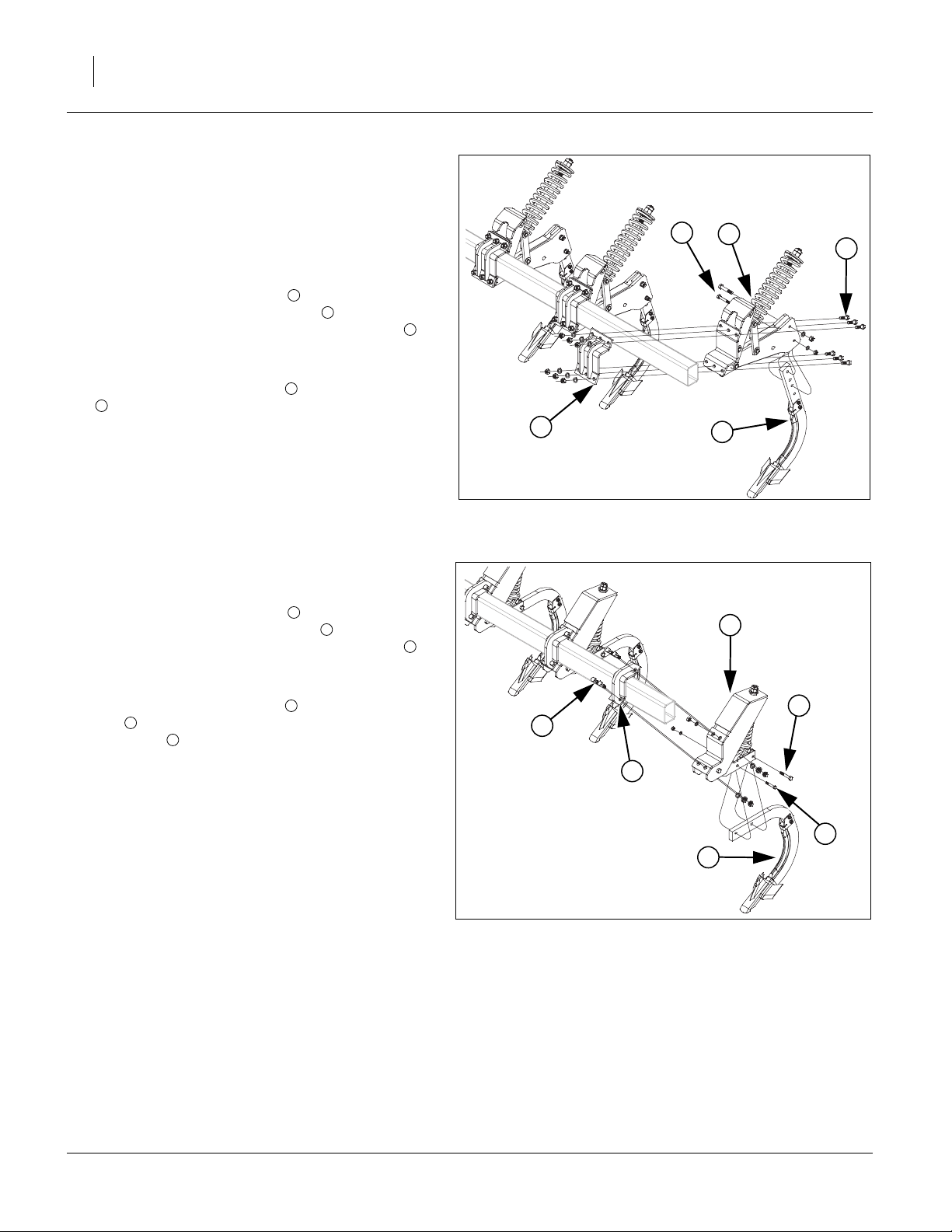
569-190S Shank
Note: See machine layouts in Appendix for proper shank
placement. The front and rear shank mount assemblies will be shipped pre assembled from factory in
two parts in boxes. There will be the mount assembly and the shank assembly.
Refer to Figure 10
59. Install the mount assembly to the rear side of
tubes. Install front mount bracket on front of tubes,
align holes, secure with 3/4 x 2 1/2 hex bolts , 3/4
lock washers and 3/4 nuts. Slide these two parts
over frame tube in proper location.
60. Attach the shank assembly with 3/4 x 4 hex bolts
, 3/4 lock washers and 3/4 nuts.
5
61. Tighten all bolts to specs, See “Torque Values
Chart” on page 27.
1
2
3
4
2
5
1
3
4
569-196S Shank
Refer to Figure 11
62. Install the mount assembly to the rear side of
tubes. Install front mount bracket on front of tubes,
align holes, secure with 3/4 x 2 1/2 hex bolts , 3/4
lock washers and 3/4 nuts. Slide these two parts
over frame tube in proper location.
63. Attach the shank assembly with 5/8 x 4 1/2 hex
bolt , 5/8 lock washer and 5/8 nut (rear hole), 1/2 x
5
3 hex bolt , 1/2 lock washer and 1/2 nut (front
hole).
64. Tighten all bolts to specs, See “Torque Values
Chart” on page 27.
5
1
2
3
4
Figure 10
569-190S Shank
42011
1
5
3
2
6
4
Figure 11
596-196S Shank
41668
566-170Q-ENG 03/17/2014
Great Plains Manufacturing, Inc. Assembly 13
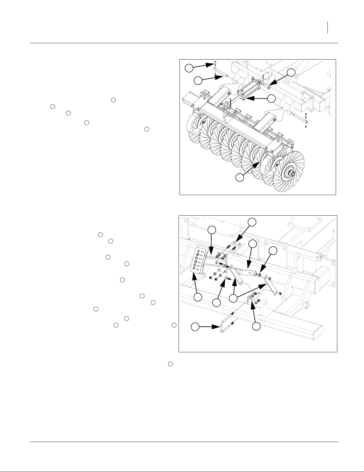
Turbo Gang
Note: See machine layouts in Appendix for proper gang
placement. The gang assemblies will come pre assembled from factory and attached to the gang bar.
Refer to Figure 12
65. Install the gang assembly using 1 x 9 1/2 hinge
pin , secure with 3/8 x 2 1/4 Gr. 8, special thread
2
hex bolts , 3/8 top lock nuts.
66. Attach cylinders to ears on gang bars and gang
mounts with, secure with 1 x 3 1/8 pins , 1.5 x 1.0
x.075 machine washers and 3/16 x 2 cotter pins.
67. Tighten all bolts to specs, See “Torque Values
Chart” on page 27.
3
4
1
4
3
5
2
4
1
Depth Gauge
Refer to Figure 13
68. Install the link mount to the center gang bar with
1/2 x 3 1/32 x 7 1/4 u-bolt , 1/2 lock washers and 1/
2 nuts.
69. Install leveling weldment to the center gang mount
with 1/2 x 5 1/32 x 4 1/2 u-bolts , 1/2 lock washers
and 1/2 nuts.
70. Slide the depth gauge pointer over the leveling
weldment bolt, secure with 1/2 lock nut.
71. Align one set of holes in the two links , one on
each side of the depth gauge pointer hole , secure
with 1/2 x 1 1/2 bolt and 1/2 lock nut.
72. Attach the other end of the links , one on each side
of the hole in the link mount with 1/2 x 1 1/2 bolt
and 1/2 lock nut.
73. Tighten all u-bolts to specs, See “Torque Values
Chart” on page 27. Tighten the three lock nuts up
snug, but be sure the links will pivot.
74. Clean the surface where TC depth coulter decal
goes and peel backing off of decal and fasten decal
on plate. Firmly press decal to get all air bubbles out.
1
2
3
4
5
7
5
8
7
1 8
9
Figure 12
Turbo Gang
42013
4
3
5
6
9
2
7
8
1
Figure 13
Depth Gauge
41668
03/17/2014 566-170Q-ENG
 Loading...