

Page 1
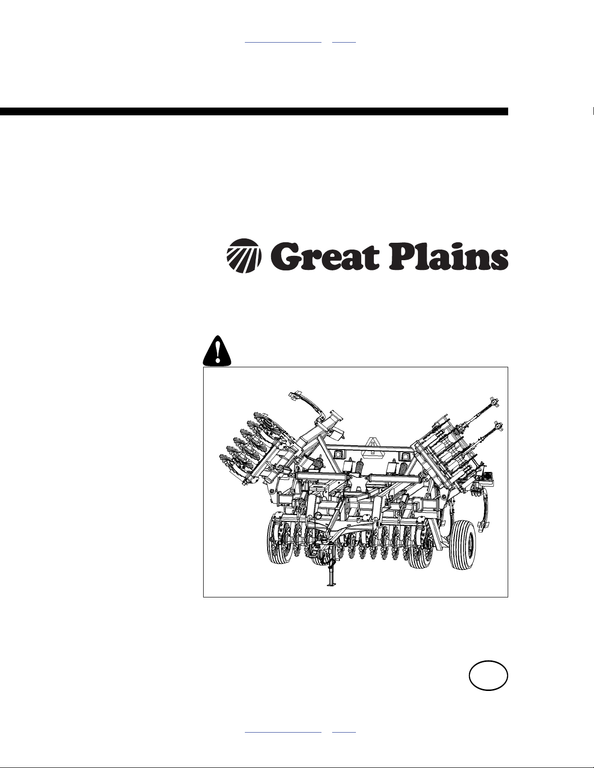
Table of Contents Index
Assembly Manual
5313, 5315, 5317, 5319, 5321 & 5323
5109, 5111, 5113, 5115,
Turbo-Chisel (S/N A1420X+)
Manufacturing, Inc.
www.greatplainsmfg.com
Read the operator’s manual entirely. When you see this symbol, the
subsequent instructions and warnings are serious - follow without
exception. Your life and the lives of others depend on it!
Illustrations may show optional equipment not supplied with standard unit.
41298
ORIGINAL INSTRUCTIONS
© Copyright 2014 Printed 2014-03-06 566-224Q-ENG
Table of Contents Index
EN
Page 2

Table of Contents Index
Table of Contents Index
Page 3

Great Plains Manufacturing, Inc. iii
Table of Contents
Important Safety Information ..................................... 1
Introduction ..................................................................4
Description of Unit ..........................................................4
Models Covered ............................................................. 4
Document Family ...........................................................4
Tools Required ...............................................................4
Pre-assembly Checklist..................................................4
Using This Manual..........................................................5
Definitions................................................................... 5
Shipping Inventory..........................................................6
Unloading ....................................................................... 6
Unpacking Components .............................................6
Unload Smaller Items First .........................................6
Unpacking Boxes .......................................................6
Assembly and Setup Assistance ................................6
Assembly ......................................................................7
Center Transport ........................................................7
5317-5323 Wing Transport......................................... 7
Center Lift & Gang Mount........................................... 8
Trusses..................................................................... 10
Hitch & Center Lift Assembly.................................... 12
5109-5315 Center Fold ............................................14
5317-5323 Center Fold ............................................16
5313-5315 Wings .....................................................18
5317-5323 Wings .....................................................18
5317-5323 Wing Fold Cylinders ...............................20
569-190S Shank....................................................... 22
569-196S Shank....................................................... 22
Turbo Gang ..............................................................23
Depth Gauge ............................................................23
Valve, Fitting and Hose Assembly................................24
Depth Stop ...............................................................24
Install Rebound Valve and O-Ring Fittings...............24
Bypass Valve............................................................ 25
Pilot Check Valve .....................................................25
Install Depth Control Valve and O-Ring Fittings.......25
Install Hose Handle and JIC Fittings ........................26
Attach Hose Clamps and Hose wraps...................... 27
Hydraulic Hose Hookup............................................ 27
Hose Handles...........................................................28
Purging Hydraulic System ........................................28
Lights........................................................................29
Install Rear Hitch (optional) ......................................29
Completing Setup.....................................................30
Appendix..................................................................... 31
Torque Values Chart.................................................... 31
Tire Inflation Chart ....................................................... 32
Hydraulic Connectors and Torque ............................... 32
TC5109-TC5315 Hydraulic Lift Layout......................... 33
TC5317-TC5323 Hydraulic Lift Layout......................... 34
TC5313-TC5315 Hydraulic Fold Layout ...................... 35
TC5317-TC5323 Hydraulic Fold Layout ...................... 36
TC5109 Hydraulic Gang Layout................................... 37
TC5111-TC5323 Hydraulic Gang Layout..................... 38
TC5109 Machine Layout.............................................. 39
TC5111 Machine Layout.............................................. 40
TC5113 Machine Layout.............................................. 41
TC5115 Machine Layout.............................................. 42
TC5313 Machine Layout.............................................. 43
TC5315 Machine Layout.............................................. 44
TC5317 Machine Layout.............................................. 45
TC5319 Machine Layout.............................................. 46
TC5321 Machine Layout.............................................. 47
TC5323 Machine Layout.............................................. 48
Twisted Shovel Layout (9 13 17 21 Shank) ................. 49
Twisted Shovel Layout 11 15 19 23 Shank) ................ 50
TC5109 Chopper Reel Layout ..................................... 51
TC5111 Chopper Reel Layout ..................................... 52
TC5113 Chopper Reel Layout ..................................... 53
TC5115 Chopper Reel Layout ..................................... 54
TC5313 Chopper Reel Layout ..................................... 55
TC5315 Chopper Reel Layout ..................................... 56
TC5317 Chopper Reel Layout ..................................... 57
TC5319 Chopper Reel Layout ..................................... 58
TC5321 Chopper Reel Layout ..................................... 59
TC5323 Chopper Reel Layout ..................................... 60
TC5109 Buster Bar Layout .......................................... 61
TC5111 Buster Bar Layout .......................................... 62
TC5113 Buster Bar Layout .......................................... 63
TC5115 Buster Bar Layout .......................................... 64
TC5313 Buster Bar Layout .......................................... 65
TC5315 Buster Bar Layout .......................................... 66
TC5317 Buster Bar Layout .......................................... 67
TC5319 Buster Bar Layout .......................................... 68
TC5321 Buster Bar Layout .......................................... 69
TC5323 Buster Bar Layout .......................................... 70
Index............................................................................ 71
© Copyright 2006, 2007, 2008, 2009, 2010, 2011, 2012, 2013, 2014 All rights Reserved
Great Plains Manufacturing, Inc. provides this publication “as is” without warranty of any kind, either expressed or implied. While every precaution has been
taken in the preparation of this manual, Great Plains Manufacturing, Inc. assumes no responsibility for errors or omissions. Neither is any liability assumed for
damages resulting from the use of the information contained herein. Great Plains Manufacturing, Inc. reserves the right to revise and improve its products as
it sees fit. This publication describes the state of this product at the time of its publication, and may not reflect the product in the future.
03/06/2014 566-224Q-ENG
Trademarks of Great Plains Manufacturing, Inc. include: Singulator Plus, Swath Command, Terra-Tine.
Registered Trademarks of Great Plains Manufacturing, Inc. include:
Air-Pro, Clear-Shot, Discovator, Great Plains, Land Pride, MeterCone, Nutri-Pro, Seed-Lok, Solid Stand,
Terra-Guard, Turbo-Chisel, Turbo-Chopper, Turbo Max, Turbo-Till, Ultra-Till, Verti-Till, Whirlfilter, Yield-Pro.
Brand and Product Names that appear and are owned by others are trademarks of their respective owners.
Printed in the United States of America
Page 4

iv TC5109-5323 Great Plains Manufacturing, Inc.
566-224Q-ENG 03/06/2014
Page 5
Great Plains Manufacturing, Inc. 1
Important Safety Information
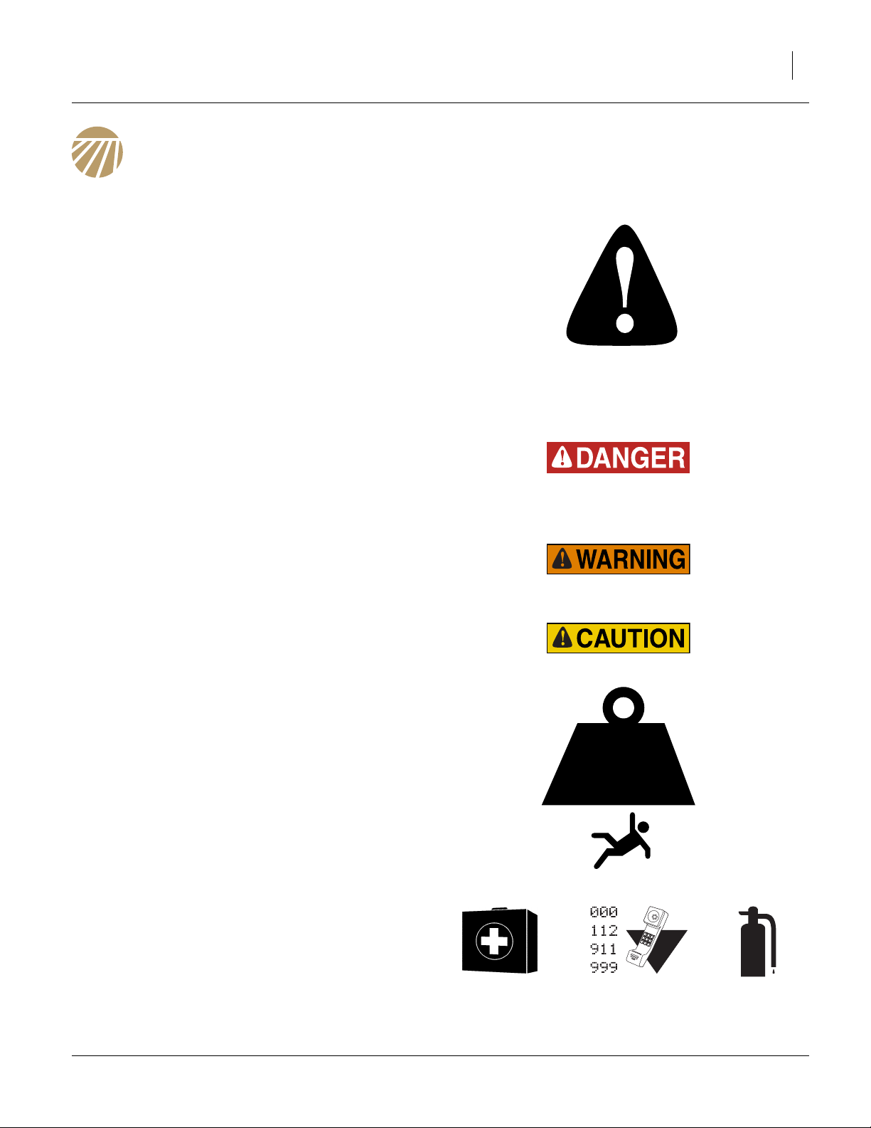
Look for Safety Symbol
The SAFETY ALERT SYMBOL indicates there is a
potential hazard to personal safety involved and extra
safety precaution must be taken. When you see this
symbol, be alert and carefully read the message that follows it. In addition to design and configuration of equipment, hazard control and accident prevention are
dependent upon the awareness, concern, prudence and
proper training of personnel involved in the operation,
transport, maintenance and storage of equipment.
Be Aware of Signal Words
Signal words designate a degree or level of hazard seriousness.
DANGER indicates an imminently hazardous situation
which, if not avoided, will result in death or serious injury.
This signal word is limited to the most extreme situations,
typically for machine components that, for functional purposes, cannot be guarded.
WARNING indicates a potentially hazardous situation
which, if not avoided, could result in death or serious
injury, and includes hazards that are exposed when
guards are removed. It may also be used to alert against
unsafe practices.
CAUTION indicates a potentially hazardous situation
which, if not avoided, may result in minor or moderate
injury. It may also be used to alert against unsafe practices.
Use Adequate Lifting Means
The frame sections and gangs of this machine are
extremely heavy. If using multiple lifters, make sure each
is rated for at least its share of the load.
> 14,000
POUNDS
Prepare for Emergencies
▲ Be prepared if a fire starts
▲ Keep a first aid kit and fire extinguisher handy.
▲ Keep emergency numbers for doctor, ambulance, hospital
and fire department near phone.
03/06/2014 566-224Q-ENG
Page 6
2 TC5109-5323 Great Plains Manufacturing, Inc.
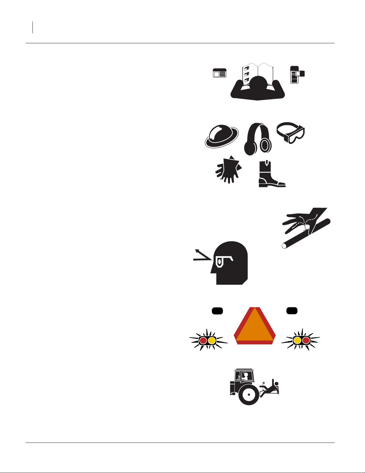
Be Familiar with Safety Decals
▲ Read and understand the “Safety Decals” section of the
Operators Manual.
▲ Read all instructions noted on the decals.
▲ Keep decals clean. Replace damaged, faded and illegible
decals.
Wear Protective Equipment
▲ Wear protective clothing and equipment.
▲ Wear clothing and equipment appropriate for the job. Avoid
loose-fitting clothing.
▲ Because prolonged exposure to loud noise can cause hear-
ing impairment or hearing loss, wear suitable hearing protection such as earmuffs or earplugs.
▲ Because operating equipment safely requires your full
attention, avoid wearing entertainment headphones while
operating machinery.
Avoid High Pressure Fluids
Escaping fluid under pressure can penetrate the skin,
causing serious injury.
▲ Avoid the hazard by relieving pressure before disconnecting
hydraulic lines.
▲ Use a piece of paper or cardboard, NOT BODY PARTS, to
check for suspected leaks.
▲ Wear protective gloves and safety glasses or goggles when
working with hydraulic systems.
▲ If an accident occurs, seek immediate medical assistance
from a physician familiar with this type of injury.
Use Safety Lights and Devices
Slow-moving tractors and towed implements can create
a hazard when driven on public roads. They are difficult
to see, especially at night.
▲ Use flashing warning lights and turn signals whenever driv-
ing on public roads.
Use lights and devices provided with implement
Keep Riders Off Machinery
Riders obstruct the operator’s view. Riders could be
struck by foreign objects or thrown from the machine.
▲ Never allow children to operate equipment.
▲ Keep all bystanders away from machine during operation.
566-224Q-ENG 03/06/2014
Page 7
Great Plains Manufacturing, Inc. Important Safety Information 3
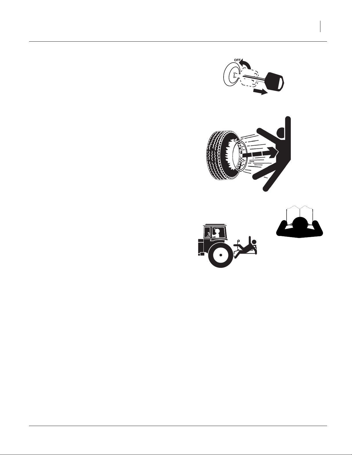
Shutdown and Storage
▲ Lower implement, put tractor in park, turn off engine, and
remove the key.
▲ Secure Turbo-Chisel using blocks and supports provided.
▲ Detach and store Turbo-Chisel in an area where children
normally do not play.
Tire Safety
Tire changing can be dangerous and should be performed by trained personnel using correct tools and
equipment.
▲ When inflating tires, use a clip-on chuck and extension hose
long enough for you to stand to one side–not in front of or
over tire assembly. Use a safety cage if available.
▲ When removing and installing wheels, use wheel-handling
equipment adequate for weight involved.
Safety At All Times
Thoroughly read and understand the instructions in this
manual before operation. Read all instructions noted on
the safety decals.
▲ Be familiar with all machine functions.
▲ Operate machinery from the driver’s seat only.
▲ Do not leave machine unattended with tractor engine run-
ning.
▲ Do not stand between the tractor and machine during
hitching.
▲ Keep hands, feet and clothing away from power-driven
parts.
▲ Wear snug-fitting clothing to avoid entanglement with mov-
ing parts.
▲ Watch out for wires, trees, etc., when folding and raising
machine. Make sure all persons are clear of working area.
03/06/2014 566-224Q-ENG
Page 8

4 TC5109-5323 Great Plains Manufacturing, Inc.
Introduction
The Turbo-Chisel has been designed with care and built
by skilled workers using quality materials. Proper setup,
maintenance, and safe operating practices will help the
customer get years of satisfactory use from the machine.
Description of Unit
The TC5109-5323 Turbo-Chisel is a one or three-section
“vertical” tillage tool. Working width ranges from 11 to 29
feet. The implement is designed to cut, size and bury residue. It can work up to 11” deep, will dislodge rootballs and
leave the field smooth enough for “one pass” finishing in
Spring. For optimum leveling of your machine, it should be
equipped with either a Chopper Reel or Buster Bar attachment.
Models Covered
TC5109 11-Foot 1-section
TC5111 14-Foot 1-section
TC5113 16-Foot 1-section
TC5115 19-Foot 1-section
TC5313 16-Foot 3-section
TC5315 19-Foot 3-section
TC5317 21-Foot 3-section
TC5319 24-Foot 3-section
TC5321 26-Foot 3-section
TC5323 29-Foot 3-section
Document Family
566-224Q-ENG Assembly Manual (this document)
566-224Q Pre-Delivery Manual
566-224M Operator Manual
566-224P Parts Manual
Tools Required
• Basic Hand Tools
• Torque Wrench
• Fork Truck, Overhead Hoist or Loader
Figure 1
Turbo-Chisel
41977
Pre-assembly Checklist
1. Before assembling, read and understand “Important
Safety Information” in front part of this manual.
2. Have at least two people on hand while assembling.
566-224Q-ENG 03/06/2014
3. Make sure area is level and free of obstructions
(preferably an open concrete area).
4. Have all major components
5. Have all fasteners and pins shipped with machine.
Page 9
Great Plains Manufacturing, Inc. Introduction 5
Using This Manual
This manual was written to help you assemble and prepare the new machine for the customer. The manual
includes instructions for assembly and setup. Read this
manual and follow the recommendations for safe, efficient and proper assembly and setup.
An operator’s and parts manual is also provided with the
new machine. Read and understand “Important Safety
Information” and “Operating Instructions” in the operator’s manual before assembling the machine. Refer to
the parts manual for proper part’s identification. As a reference, keep the operator’s and part’s manual on hand
while assembling.
The information in this manual is current at printing.
Some parts may change to assure top performance.
Definitions
The following terms are used throughout this manual.
A crucial point of information related to the preceding topic.
Read and follow the directions to remain safe, avoid serious
damage to equipment and ensure desired field results.
Note: Useful information related to the preceding topic.
Right-hand and left-hand as used in
this manual are determined by facing
the direction the machine will travel
while in use unless otherwise stated.
An orientation rose in some line art
illustrations shows the directions of: Up,
Back, Left, Down, Front, Right.
R
F
U
B
L
D
R
L
Figure 2
Right / Left
41977
03/06/2014 566-224Q-ENG
Page 10
6 TC5109-5323 Great Plains Manufacturing, Inc.
Shipping Inventory
The Turbo-Chisel will be shipped unassembled as
shown in a big shipping rack and shipping boxes on pallets. The only parts that will be assembled are the turbo
gang assemblies and reel attachment assemblies. The
reel attachments (if equipped) will be banded together
with the gang assemblies on pallet.
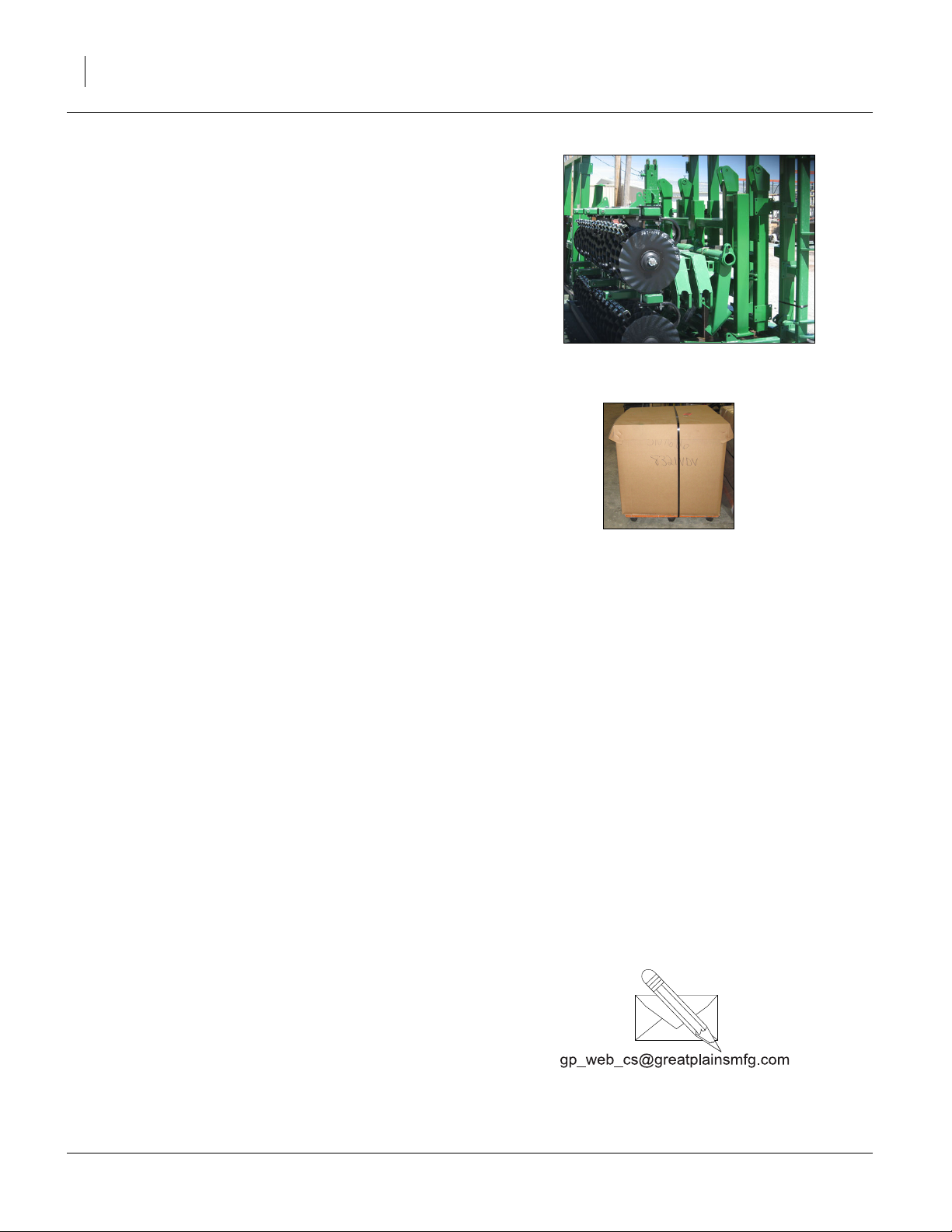
Refer to Figure 3
• All frame sections, hitch and torque tubes will be
shipped in shipping container.
41356
Refer to Figure 4
• Shank parts (mount assembly and shank assembly),
small parts and bolts will be shipped in boxes. Rear
attachment big parts will be banded to attachment
smaller parts box.
Shipping containers do not need to be returned to Great
Plains.
Figure 3
Shipping Rack
Unloading
Once everything is unloaded from “storage pod” you may
proceed with taking parts out of shipping containers.
Carefully move everything to level site and prepare to un
pack items.
Unpacking Components
Be sure you have read and understood the Important
Safety Information, starting on page 1 of this manual,
before you start unpacking components.
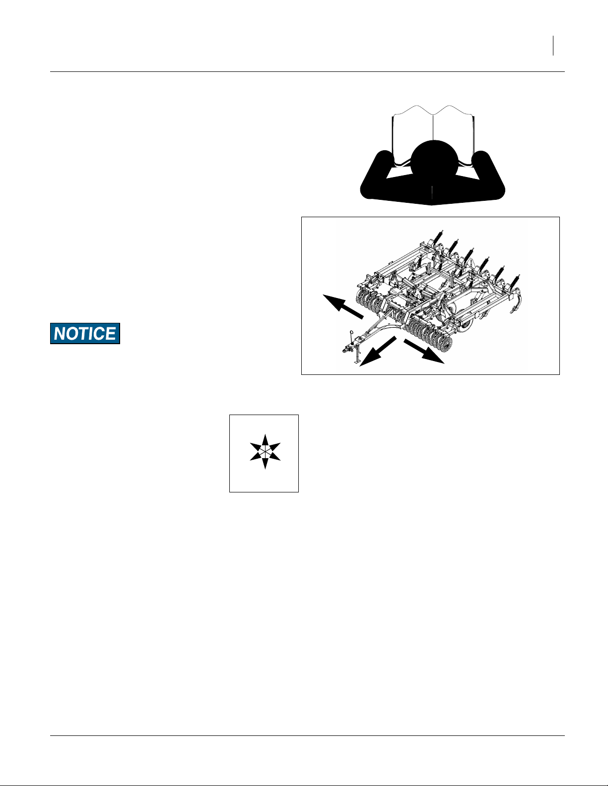
Centering components:
Be sure and center fork truck or chains (overhead hoist)
on components so they won’t slide and cause injury.
Carefully un-band components.
Now unload individual components one at a time using a
fork truck or overhead hoist.
Move each component out of the way so you have plenty
of room to remove the next one.
Unload Smaller Items First
Unloading the frames is a potentially dangerous operation.
Reduce risk and complication by first unloading
6. the tire wheel assemblies,
7. the smaller items
Place these components well out of the maneuvering
area needed for unloading the gang assemblies and
frames.
Figure 4
Shipping Boxes
8. Carefully unload the Frames and hitch out of shipping rack
41621
Unpacking Boxes
9. Carefully remove banding and lids from boxes.
10. Locate and identify all components before assembling.
Assembly and Setup Assistance
To order additional copies of pre-delivery instructions or
operator.s and parts manuals, write to the following
address. Include model numbers in all correspondence.
If you do not understand any part of this manual or have
any assembly or setup questions, assistance is available.
Contact:
Product Support
Great Plains Mfg. Inc., Service Department
PO Box 5060
Salina, KS 67402-5060
(800)255-9215
566-224Q-ENG 03/06/2014
Page 11
Great Plains Manufacturing, Inc. 7
Assembly
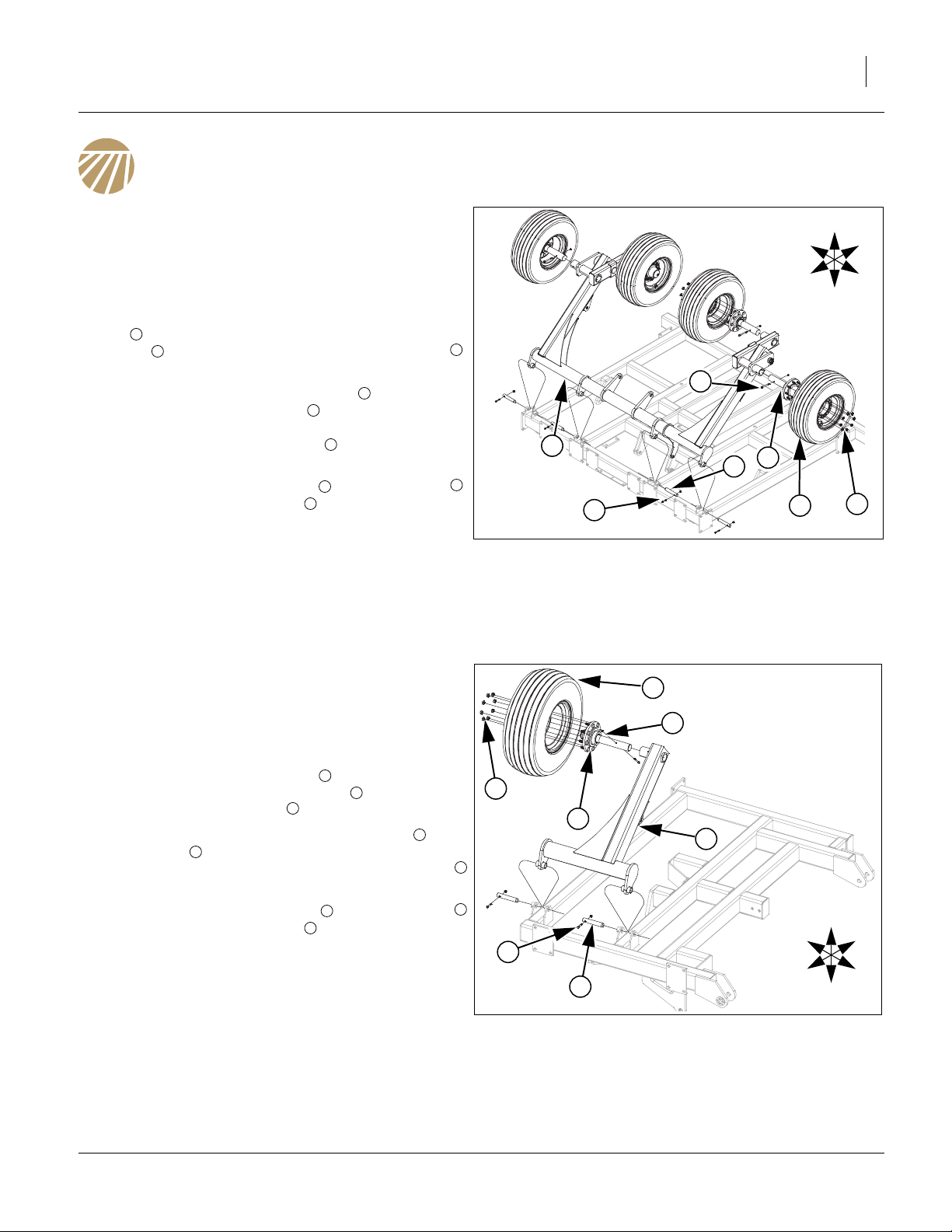
Center Transport
Refer to Figure 5
11. Once the center Frame has been uncrated, carefully
turn the center frame upside down and set on blocks
to assemble torque tube/walking beam assembly.
12. Carefully raise the torque tube/walking beam assembly with an overhead hoist and secure with 1 1/4 x
1
7 pins , 3/8 x 2 1/4 Gr. 8 special thread hex bolts
and 3/8 top lock nut.
13. Install pre-assembled hub assembly into torque
tube/walking beam assembly . Align hole in spindle
with hole in torque tube/walking beam assembly,
secure with 1/2 x 4 1/2 hex bolt and 1/2 top lock
nut.
14. Attach the tire/wheel assembly to hub assembly
and secure with 5/8 lug nuts .
15. All bolts may be tightened to specs, See “Torque
Values Chart” on page 31.
Note: Fasten the bottom of the torque tube to frame with
2
4
1
5
6
7
chain or straps so it does not swing down and hit
something while turning center frame over. Carefully use hoist to turn center frame over and set on
stands to finish assembling components.
3
4
U
R
F
B
L
D
5
1
3
Figure 5
Center Transport
4
2
6
7
42675
5317-5323 Wing Transport
Refer to Figure 6
16. Once the wing Frame has been uncrated, carefully
turn the wing frame upside down and set on blocks to
assemble torque tube.
17. Carefully raise the torque tube with an overhead
hoist and secure with 1 1/4 x 7 pins , 3/8 x 2 1/4 Gr.
8 special thread hex bolts and 3/8 top lock nut.
18. Install pre-assembled 8-bolt hub assemblies into
torque tube . Align holes in spindle with hole in
torque tube, secure with 5/16 x 3 1/2 Gr. 8 hex bolt
and 5/16 top lock nut.
19. Attach the tire/wheel assembly to hub assembly
and secure with 5/8 lug nuts .
20. All bolts may be tightened to specs, See “Torque Val-
ues Chart” on page 31.
Note: Fasten the bottom of the torque tube to frame with
chain or straps so it does not swing down and hit
something while turning center frame over. Carefully use hoist to turn center frame over and set on
stands to finish assembling components.
1
1
2
3
4
5
6
7
4
6
5
7
4
1
U
R
B
3
2
F
Figure 6
5317-5323 Wing Transport
L
D
42676
03/06/2014 566-224Q-ENG
Page 12

8 TC5109-5323 Great Plains Manufacturing, Inc.
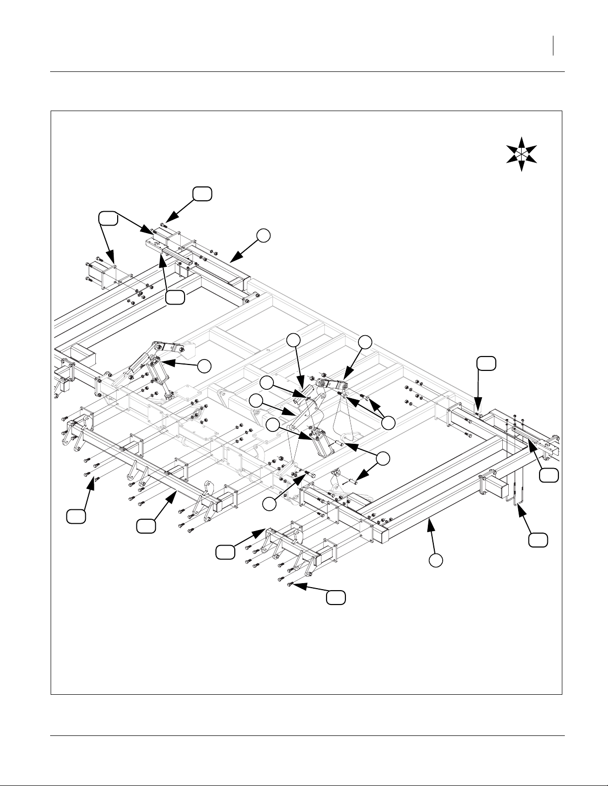
Center Lift & Gang Mount
Refer to Figure 7
21. Attach the cylinder mount bars and lift link to
center frame using 1 x 3 1/2 hex bolts , 1 x 4 hex
bolts and 1 lock nuts.
4
22. Now install 4.5 x 10 cylinders using 1 x 3 1/8 pins
, 1.5 x 1.0 x.075 machine washers and 3/16 x 2
6
1 2
3
5
cotter pins.
23. Install cylinder transport locks to cylinder mount
bars using the 5/16 wire retainer pin .
1 8
24. On models 5111-5115 fasten wings to center
frame with 3/4 x 2 1/2 hex bolts , 3/4 lock washers
7
9
10
and 3/4 nuts.
Note: Wing shank mounts are only used on a few
11
models, see machine and attachment layout drawings in Appendix for proper placement.
25. Attach outside wing shank mounts (if equipped)
with 3/4 x 2 1/2 hex bolts 3/4 lock washers and 3/
10
11
4 nuts.
26. Attach center gang mount and wing gang mounts
13
to front of center frame and wing frame with 3/4 x
2 hex bolts , 3/4 lock washers and 3/4 nuts.
14
12
Note: See machine layout section for proper light
bracket placement.
27. Fasten light bracket LH to center frame with 1/2 x
4 1/32 x 7 1/4 u-bolts , 1/2 lock washers and 1/2
15
17
huts. Repeat same procedure for light bracket RH
.
16
28. All bolts may be tightened to specs, See “Torque
Values Chart” on page 31.
566-224Q-ENG 03/06/2014
Page 13
Great Plains Manufacturing, Inc. Assembly 9
U
R
B
11
16
10
5
F
L
D
9
7
2
10
8
1
5
3
6
15
4
14
12
17
13
9
14
14
Figure 7
Center Lift & Gang Mount
03/06/2014 566-224Q-ENG
42677
Page 14

10 TC5109-5323 Great Plains Manufacturing, Inc.
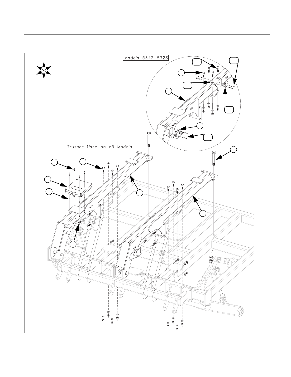
Trusses
Refer to Figure 8
Note: Do not tighten any bolts until all parts are assem-
bled.
29. Start by bolting the rear of the LH and RH
1 2
trusses to center frame using 1 1/4x81/2Gr.8hex
bolts , 1 1/4 lock washers and 1 1/4 nuts. Attach
3
middle plates of trusses with 3/4 x 2 1/2 hex bolts ,
3/4 lock washers, 3/4 nuts, front plates with 3/4 x 2
3/4 lock washers, and 3/4 nuts.
30. Mount the manual pack to RH truss plate with 1/
4 x 1 hex bolts , mini end press wheels , 1/4 lock
7 8
6 2
washers and 1/4 nuts.
31. Models 5317-5323, attach the bypass valve to the
RH truss with 5/16 x 3 hex bolts , 5/16 lock
2
10
washers and 5/16 nuts.
32. Models 5317-5323, install the rebound valve plate
with two 3/4 x 3 hex bolts , 3/4 lock washers, 3/4
4
5
nuts.
33. Models 5317-5323, install the pilot operated check
valve to rebound valve plate with 5/16 x 2 hex
13 11
bolts , 5/16 lock washers, 5/16 nuts
14
12
34. All bolts may be tightened to specs, See “Torque
Values Chart” on page 31.
9
11
566-224Q-ENG 03/06/2014
Page 15
Great Plains Manufacturing, Inc. Assembly 11
R
F
U
D
B
12
14
4
L
11
2
13
9
10
3
7
4
6
8
2
1
5
Figure 8
Trusses
42678
03/06/2014 566-224Q-ENG
Page 16

12 TC5109-5323 Great Plains Manufacturing, Inc.
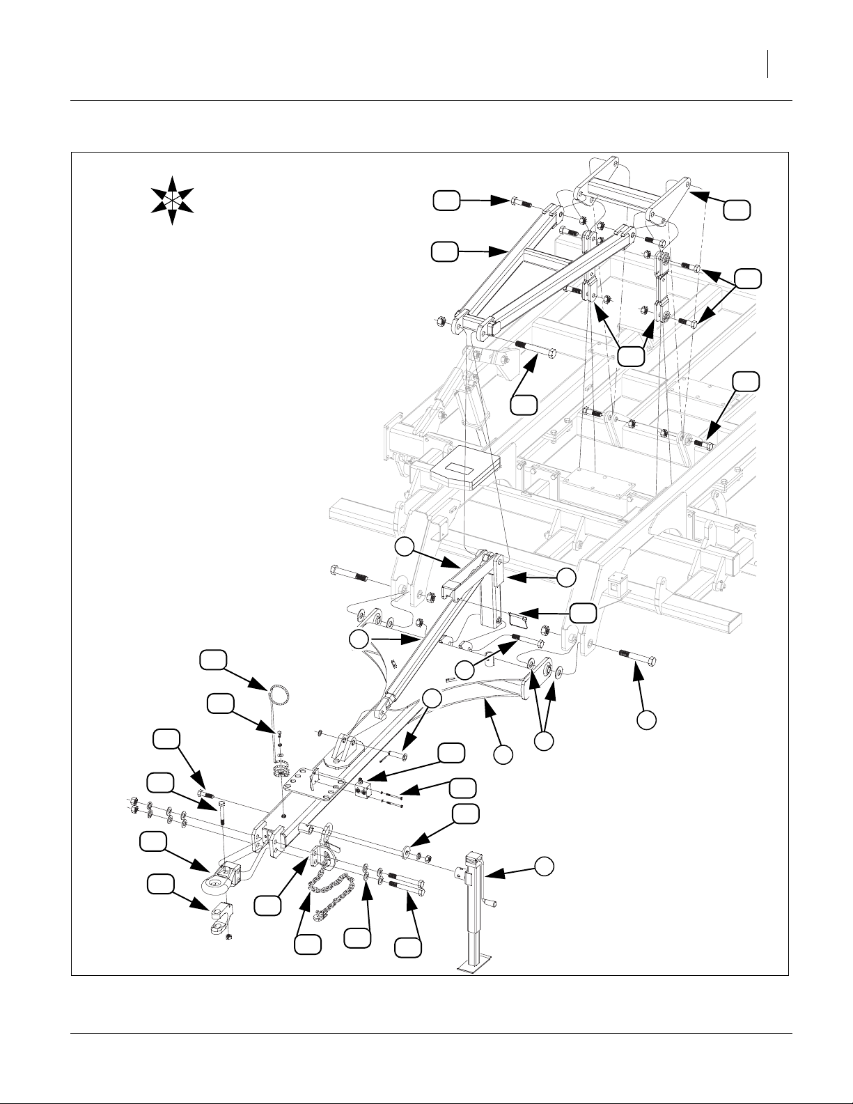
Hitch & Center Lift Assembly
Refer to Figure 9
35. Attach hitch pole to trusses using 1 1/4 x 8 Gr. 8
hex bolts , 1 1/4 flat washers (one on each side
2 3
1
of uni-ball) and top lock nuts. Washers are needed to
ensure a tight fit. Bolts need tightened securely, but
do not over-tighten as the hitch needs to pivot.
36. Mount square jack to front mount on hitch with
4 1
pin provided with jack. Use jack to help support front
of hitch for rest of hitch assembly.
37. The front of the hitch turnbuckle may be attached
to the hitch pole ears with 1 x 3 5/8 clevis pin , 1.5 x
5
6
1.0 x.075 machine washers and 3/16 x 2 cotter pins.
38. Attach bottom hole of hitch leveling arm to ears on
back of hitch pole with 1 x 7 Gr. 8 hex bolts and
1 8
7
1 lock nuts
39. Attach the back of the hitch turnbuckle to the top
ears of hitch leveling arm , turnbuckle lock and
level bar with 1 1/4 x 9 special thread hex bolt
11
7 9
5
12
and 1 1/4 lock nut. Attach the 3/8 x 4 pin wire snap
lock to the turnbuckle lock.
10
40. Attach front holes of h-bracket to rear of level bar
with 1 x 4 hex bolts , and 1 lock nuts.
11 15
41. Attach middle holes of h-bracket to top holes of lift
straps and bottom holes of lift straps to ears on
14 14
torque tube with 1 x 3 1/2 hex bolts , and 1 lock
13
13
16
nuts.
42. Attach rear holes of h-bracket to ears on center
frame with 1 x 3 1/2 hex bolts , and 1 lock nuts.
43. Align holes in safety chain support , cat III hitch
tongue with holes on left side of hitch pole ,
18
secure with 1 x 8 Gr. 8 special hex bolts , four, 1
SAE flat washers , lock washers and 1 nut.
44. Install safety chain on bottom side of hitch pole ,
20
21
secure with 7/8 x 3 hex bolt , 7/8 flat washer , 7/
13
16
17
1
19
1
22 23
8 lock washer and 7/8 nut.
45. Attach hitch clevis to cat III hitch tongue with 3/
4 x 5 1/2 Gr. 8 hex bolt and 3/4 lock nut.
Note: Do not use hitch clevis if tractor has a hammer
24 18
25
24
strap. Use for transporting with truck.
46. Route safety chain through safety chain support
.
17
47. Attach hose holder to nut on front hitch pole
with 1/2 x 1 hex bolt ,1/2 flat washer and 1/2 lock
21
26
1
22
washer.
48. Attach counterbalance valve to the plate on front
of hitch pole with 5/16 x 3 1/2 hex bolts and 5/
1
28
29
16 lock washers.
49. All bolts may be tightened to specs, See “Torque
Values Chart” on page 31.
566-224Q-ENG 03/06/2014
Page 17
Great Plains Manufacturing, Inc. Assembly 13
U
R
F
B
L
15
13
D
11
16
14
16
12
25
18
24
22
26
27
17
21
5
20
9
19
7
10
8
6
2
3
28
1
29
23
4
Figure 9
Hitch & Center Lift
03/06/2014 566-224Q-ENG
42679
Page 18

14 TC5109-5323 Great Plains Manufacturing, Inc.
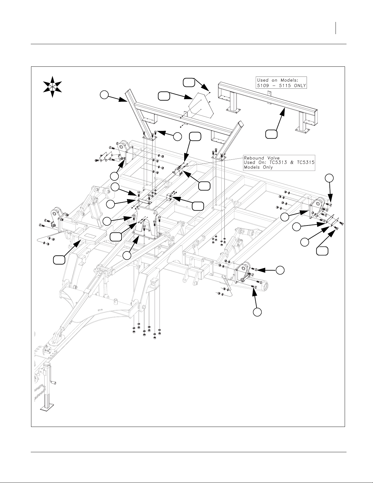
5109-5315 Center Fold
Refer to Figure 10
50. Install center fold bracket and rebound valve
bracket to front center frame plate with 3/4 x 2 1/2
hex bolts , 3/4 lock washers and 3/4 nuts.
2
3
51. Attach center wing stop (Models 5313 & 5315
only) to truss plates with 5/8 x 1 1/2 hex bolts , 5/8
lock washers and 5/8 nuts.
52. Attach bolt on wing pivots on side of center frame
with 3/4 x 2 1/4 hex bolts , 3/4 lock washers and 3/
4 nuts.
53. Attach 12ga 16ga shim’s as needed with 3/4 x 1
1/2 hex bolts , 3/4 lock washers and 3/4 nuts to
8 9
10
level wings.
1
4
5
6
7
Note: See “Operator’s Manual” general operation and in-
field adjustment section for adjustment procedure.
Store extra shims in manual pak .
11
54. Models 5109-5115 attach rigid smv & light bracket
12
to rear truss plates with 5/8 x 1 1/2 hex bolts ,5/
5
8 lock washers and 5/8 nuts.
55. Attach SMV sign to either center wing stop or
rigid smv & light bracket with 1/4 x 3/4 pan head
screws , 1/4 lock washers and 1/4 hex nuts.
14
56. Models 5313-5315 attach rebound valve with 5/
16 x 4 hex bolts , 5/16 lock washers and 5/16 nuts.
57. Attach double block tee with 5/16 x 3 1/2 hex bolts
, 5/16 lock washers and 5/16 nuts.
19
16
13
4
12
15
18
58. Tighten all bolts to specs, See “Torque Values
Chart” on page 31.
566-224Q-ENG 03/06/2014
Page 19
Great Plains Manufacturing, Inc. Assembly 15
U
R
B
14
F
L
4
13
D
16
5
6
3
2
15
18
3
12
7
6
8
19
9
10
11
1
7
7
Figure 10
5109-5315 Center Fold
03/06/2014 566-224Q-ENG
42680
Page 20

16 TC5109-5323 Great Plains Manufacturing, Inc.
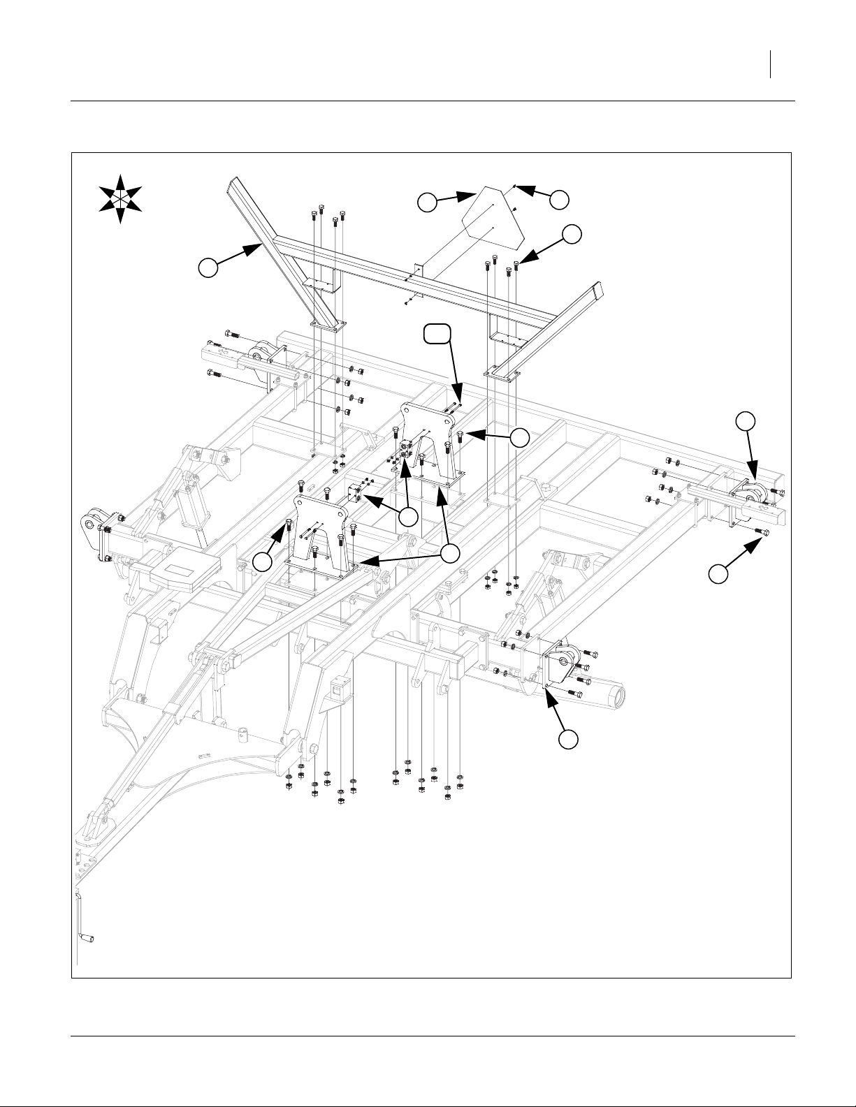
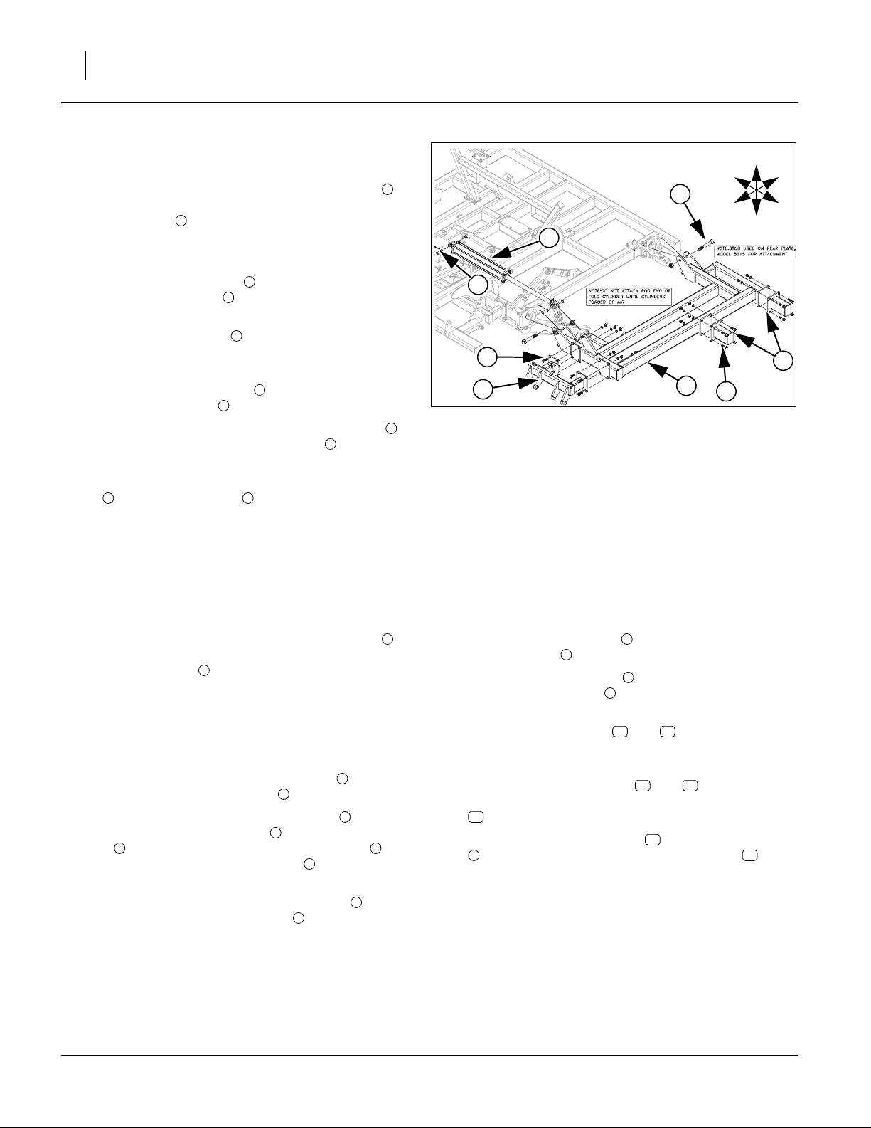
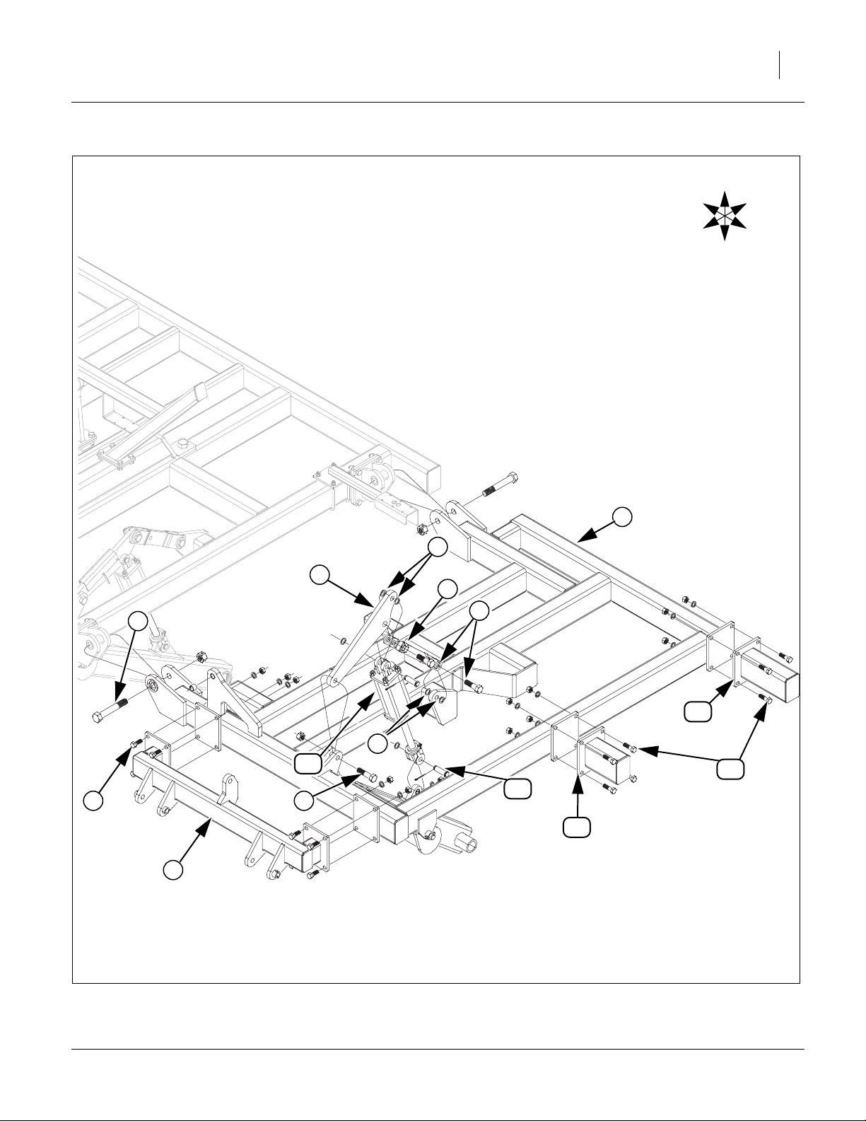
5317-5323 Center Fold
Refer to Figure 11
59. Install center fold brackets to center frame plates
with 3/4 x 2 hex bolts , 3/4 lock washers and 3/4
1
2
nuts.
60. Attach center wing stop to truss plates with 5/8 x 1
1/2 hex bolts , 5/8 lock washers and 5/8 nuts.
4
61. Attach bolt on hinge on side of center frame with
3/4 x 2 1/2 hex bolts , 3/4 lock washers and 3/4
3
5
6
nuts.
62. Attach SMV sign to center wing stop with 1/4 x
3/4 pan head screws , 1/4 lock washers and 1/4
7 3
8
hex nuts.
63. Attach double block tee on both front and rear
center fold brackets with 5/16 x 3 1/2 hex bolts , 5/
9
10
16 lock washers and 5/16 nuts.
64. Tighten all bolts to specs, See “Torque Values
Chart” on page 31.
566-224Q-ENG 03/06/2014
Page 21
Great Plains Manufacturing, Inc. Assembly 17
U
D
B
L
7
8
4
R
F
3
10
5
2
9
2
1
6
5
Figure 11
5317-5323 Center Fold
03/06/2014 566-224Q-ENG
42681
Page 22
18 TC5109-5323 Great Plains Manufacturing, Inc.
5313-5315 Wings
Refer to Figure 12
65. Carefully align holes in wing frame LH and RH with
holes on center frame hinges. Secure with 1 1/4 x 8
Gr. 8 hex bolt and 1 1/4 top lock nut.
2
Note: Tighten bolts snug but do not over-tighten as wings
need to pivot freely.
66. Attach wing gang mount to front wing frame plates
with 3/4 x 2 hex bolts , 3/4 lock washers and 3/4 hex
3
4
nuts.
Note: Wing shank mounts are only used on some mod-
5
els, see machine and attachment layout drawings in
Appendix for proper placement.
67. Install wing shank mounts to wing frame plate with
3/4 x 2 1/2 hex bolts , 3/4 lock washers and 3/4 nuts.
5
6
68. Attach base end of the 4 x 30 x 2 fold cylinders to
center fold bracket with 1 x 3 3/8 pins , 1.5 x 1.0
8
x.075 machine washer and 3/16 x 2 cotter pin.
Note: Do not attach rod end of the 4 x 30 x 2 fold cylinders
to wing cylinder lug until fold cylinders have
7 5
been purged of air, See “Purging Hydraulic Sys-
tem” on page 28.
69. Tighten all bolts to specs, See “Torque Values Chart”
on page 31.
1
7
U
R
B
2
F
L
D
7
8
4
3
Figure 12
5313-5315 Wings
1
6
5
42682
5317-5323 Wings
Refer to Figure 13
70. Carefully align holes in wing frame LH and RH
with holes on center frame hinges. Secure with 1 1/4
x 8 Gr. 8 hex bolt and 1 1/4 top lock nut.
2
Note: Tighten bolts snug but do not over-tighten as
wings need to pivot freely. When wing frame is
attached to center frame, set stands (if available)
under outer part of wings to hold wings level for
rest of assembly.
71. Attach lower hole of cylinder mount bar to ears of
wing frame with 1 x 4 hex bolt , and 1 lock nut.
7
3
72. Attach upper hole of cylinder bar mount to one
end of wheel arm turnbuckle with 1 x 3 1/2 hex
bolt , two 1.5 x 1.0 x.075 machine washers (one
5 6
in each side of cylinder bar mount ), secure with 1
4
3
lock nut.
73. Attach other end of wheel arm turnbuckle to wing
frame ear with 1 x 3 1/2 hex bolt , two 1.5 x 1.0
5
1
3
4
x.075 machine washers (one in each side of cylinder bar mount ), secure and 1 lock nut.
3
74. Attach wing gang mount to front wing frame plates
with 3/4 x 2 hex bolts , 3/4 lock washers and 3/4
6
8
9
hex nuts.
Note: Wing shank mounts and are only used on
10
11
some models, see machine and attachment layout
drawings in Appendix for proper placement.
75. Install wing shank mounts and (model 5323
10 11
only) to wing frame plate with 3/4 x 2 1/2 hex bolts
, 3/4 lock washers and 3/4 nuts.
12
76. Attach the wing lift cylinders to cylinder bar mount
and ear on torque tube with1x33/8pins , 1.5 x
3
13
14
1.0 x.075 machine washer and 3/16 x 2 cotter pin.
77. Tighten all bolts to specs, See “Torque Values
Chart” on page 31.
566-224Q-ENG 03/06/2014
Page 23
Great Plains Manufacturing, Inc. Assembly 19
U
R
B
F
L
D
1
6
3
4
2
5
11
6
13
12
14
9
7
10
8
Figure 13
5317-5323 Wings
03/06/2014 566-224Q-ENG
42683
Page 24

20 TC5109-5323 Great Plains Manufacturing, Inc.
5317-5323 Wing Fold Cylinders
Refer to Figure 14
78. Install wing fold bracket to wing frame with 3/4 x 6
hex bolts , 3/4 lock washers and 3/4 nuts.
2
79. Attach base end of the 4 x 30 fold cylinders to center fold bracket with 1 x 3 3/8 pins , 1.5 x 1.0 x.075
1
3
4
machine washer and 3/16 x 2 cotter pin.
Note: Do not attach rod end of the fold cylinders to
3
wing cylinder brackets until fold cylinders have
been purged of air, See “Purging Hydraulic Sys-
tem” on page 28.
80. Tighten all bolts to specs, See “Torque Values
Chart” on page 31.
566-224Q-ENG 03/06/2014
Page 25

Great Plains Manufacturing, Inc. Assembly 21
U
R
B
F
L
D
4
3
3
1
4
2
Figure 14
5317-5323 Wing Fold Cylinders
03/06/2014 566-224Q-ENG
42662
Page 26

22 TC5109-5323 Great Plains Manufacturing, Inc.
569-190S Shank
Note: See machine layouts in Appendix for proper shank
placement. The front and rear shank mount assemblies will be shipped pre assembled from factory in
two parts in boxes. There will be the mount assembly and the shank assembly.
Refer to Figure 15
81. Install the mount assembly to the rear side of
tubes. Install front mount bracket on front of tubes,
align holes, secure with 3/4 x 2 1/2 hex bolts , 3/4
lock washers and 3/4 nuts. Slide these two parts
over frame tube in proper location.
82. Attach the upper hole of shank assembly with 3/4
x 4 hex bolts , 3/4 lock washers and 3/4 nuts.
Attach the lower hole of shank assembly with 5/8 x
4 hex bolts , 3/4 lock nut.
83. Tighten all bolts to specs, See “Torque Values
Chart” on page 31.
5
6
1
2
3
4
4
2
5
1
3
6
4
569-196S Shank
Refer to Figure 16
84. Install the mount assembly to the rear side of
tubes. Install front mount bracket on front of tubes,
align holes, secure with 3/4 x 2 1/2 hex bolts , 3/4
lock washers and 3/4 nuts. Slide these two parts
over frame tube in proper location.
85. Attach the shank assembly with 5/8 x 4 1/2 hex
bolt , 5/8 lock washer and 5/8 nut (rear hole), 1/2 x
5
3 hex bolt , 1/2 lock washer and 1/2 nut (front
hole).
86. Tighten all bolts to specs, See “Torque Values
Chart” on page 31.
5
1
2
3
4
Figure 15
569-190S Shank
42011
1
5
3
2
6
4
Figure 16
569-196S Shank
42012
566-224Q-ENG 03/06/2014
Page 27

Great Plains Manufacturing, Inc. Assembly 23
Turbo Gang
Note: See machine layouts in Appendix for proper gang
placement. The gang assemblies will come pre assembled from factory and attached to the gang bar.
Refer to Figure 17
87. Install the gang assembly using 1 x 9 1/2 hinge
pin , secure with 3/8 x 2 1/4 Gr. 8 special thread
2
hex bolts , 3/8 top lock nuts.
88. Attach cylinders to ears on gang bars and gang
mounts, secure with 1 x 3 1/8 pins , 1.5 x 1.0 x.075
machine washers and 3/16 x 2 cotter pins.
89. Tighten all bolts to specs, See “Torque Values
Chart” on page 31.
3
4
1
5
3
5
2
4
1
Depth Gauge
Refer to Figure 18
90. Install the link mount to the center gang bar with
1/2 x 3 1/32 x 7 1/4 u-bolt , 1/2 lock washers and 1/
2 nuts.
91. Install leveling weldment to the center gang mount
with 1/2 x 5 1/32 x 4 1/2 u-bolts , 1/2 lock washers
and 1/2 nuts.
92. Slide the depth gauge pointer over the leveling
weldment bolt, secure with 1/2 lock nut.
93. Align one set of holes in the two links , one on
each side of the depth gauge pointer hole , secure
with 1/2 x 1 1/2 bolt and 1/2 lock nut.
94. Attach the other end of the links , one on each side
of the hole in the link mount with 1/2 x 1 1/2 bolt
and 1/2 lock nut.
95. Tighten all u-bolts to specs, See “Torque Values
Chart” on page 31. Tighten the three lock nuts up
snug, but be sure the links will pivot.
96. Clean the surface where TC depth coulter decal
goes and peel backing off of decal and fasten decal
on plate. Firmly press decal to get all air bubbles out.
1
2
3
4
5
7
5
8
7
1 8
9
Figure 17
Turbo Gang
42013
4
3
5
6
9
2
7
8
1
Figure 18
Depth Gauge
42016
03/06/2014 566-224Q-ENG
Page 28

24 TC5109-5323 Great Plains Manufacturing, Inc.
Valve, Fitting and Hose Assembly
Note: Refer to hydraulic layouts in Appendix for complete
hose routings
Refer to Figure 19
Depth Stop
97. Align holes in depth control valve to top of depth stop
valve mounting bracket using 5/16 x 2 hex bolts and 5/
16 lock washers.
98. Slide one end of (with 2 holes) depth stop tube through
slotted hole in depth stop valve mounting bracket. Slide
other end of depth stop tube over lever on torque tube,
secure with 1/2 x 3 hex bolt , 1/2 lock washer and 1/2
nut.
99. Bolt depth stop screw assembly to front of depth stop
tube with 1/2 x 2 1/2 hex bolts , 1/2 lock washers and
3 6
1/2 nuts.
100.Tighten all u-bolts to specs, See “Torque Values Chart”
on page 31.
Note: Install all hydraulic fittings as shown in steps below. See
hydraulic layouts in Appendix for proper hose routing.
1
2
3
3
4
5
3
2
5
6
1
Figure 19
Depth Stop
R
F
4
U
B
L
D
42017
Install Rebound Valve and O-Ring Fittings
Refer to Figure 20
101.Thread straight (non- adjustable stud) fittings into
ports V1, V2 and C2 of rebound valve .
Note: Tighten as shown below. Do not over tighten as this
could cause damage to valves.
a. Inspect all components for damage or contamination dur-
ing shipping.
b. Lubricate o-ring and threads on fitting.
c. Turn fitting into port until finger tight, See “Fittings
Torque Values” on page 32.
102.Thread elbow (adjustable stud) fitting into port C1 of
rebound valve .
a. Follow steps a and b from the foregoing instructions, then
proceed with the following steps below.
b.Looking at fitting from end with nut/washer/o-ring
assembly, turn nut clockwise as far as possible.
a. Using wrench, turn fitting into port until the washer
touches the port spot face. Continue turning fitting until
washer touches thread nearest wrench pad.
b. Back off fitting counterclockwise not exceeding one revo-
lution until it is oriented in the correct position.
c. Place wrench on the wrench pad of fitting to keep fittings
from turning, See “Fittings Torque Values” on page 32,
1
1
2
3
3
2
1
Figure 20
Rebound Valve Fittings
42621
566-224Q-ENG 03/06/2014
Page 29

Great Plains Manufacturing, Inc. Assembly 25
Bypass Valve
Refer to Figure 21
103.Attach hoses to bypass valve (Models 5317-5323
only). Hoses and fittings will have color ties to get hoses
hooked up properly.
Note: See TC5317-TC5323 Hydraulic Down Pressure in “Op-
erator’s Manual” for adjusting bypass valve.
1 2
Pilot Check Valve
Refer to Figure 22
104.Attach hoses to bypass valve (Models 5317-5323
only) located on right truss. Hoses and fittings will have
color ties to get hoses hooked up properly.
1 2
R
F
U
D
B
2
1
L
1
Figure 21
Bypass Valve
42638
2
1
1
Figure 22
Pilot Check Valve
41623
Install Depth Control Valve and O-Ring Fittings
Refer to Figure 23
105.Thread elbow (adjustable stud) fitting into left port of
depth stop valve . Thread straight (non- adjustable
stud) fittings into front port of depth control valve .
106.Tighten as shown in steps 102, 103.
1
2 1
3
1
2
3
U
R
F
B
L
D
Figure 23
Depth Control Valve Fittings
03/06/2014 566-224Q-ENG
41671
Page 30

26 TC5109-5323 Great Plains Manufacturing, Inc.
Install Hose Handle and JIC Fittings
Refer to Figure 24
Note: Hose handles are color coded. See “Hydraulic Hose
Hookup” on page 27 for proper placement on hoses.
107.Install fittings to end of hoses running to front of
hitch. Attach poppet fittings to fittings .
108.Tighten as shown in steps 102, 103.
109.Align the grooves in the front of the hose handles with
the ribs in the fittings as shown and install the self
threading screws through holes.
110.Route hoses as shown in layout section in Appendix.
111.When the JIC hoses are routed, follow the following procedure for hooking up and tightening.
a.Inspect for possible contamination or damage from
shipping or handling. Sealing surface should be
smooth. Annular tool marks of (100uin) concentric with
thread permissible.
b.Lubricate the threads and the entire surface of the cone
with hydraulic fluid or a light lubricant.
c.Align mating components for hand connection and turn
flare nut until sealing surfaces make full contact.
d.Torque nut to, See “Torque Values Chart” on page 31.
If a wrench pad is provided next to nut, place a second
wrench on pad to prevent flare from rotating while
being torqued.
e. When torquing nut onto a straight flared fitting, it may be
necessary to also place a wrench on the flared fitting
wrench pad to prevent it from turning during assembly.
112.Alternate Assembly Method for JIC.
a. If torqued method not possible, then proceed to the
steps below.
b.Lightly wrench tighten the nut until there is firm
resistance.
c. Place a wrench on wrench pad next to nut as near
the 6 0’clock position as possible.
d.Place second wrench on nut as near the 3 o’clock
position as possible.
e.Turn nut clockwise to no less than the 4 o’clock
position and no more than the 6 o’clock position.
Required rotation generally decreases as size
increases.
2 1
3 2
4
2
5
R
F
U
D
B
5
L
4
2
1
3
4
Figure 24
Hose Handle
41672
566-224Q-ENG 03/06/2014
Page 31

Great Plains Manufacturing, Inc. Assembly 27
u
e
.
Refer to Figure 25
Attach Hose Clamps and Hose wraps
113.When all the hoses are hooked up and tightened properly, put hose clamps on hoses as shown.
114.Install hose wraps on hoses as needed.
Note: Be sure and get hoses and light wiring harness fas-
tened properly so they do not drag. Check to be sure
there is enough slack in hinge area when folding machine the first time.
Hydraulic Hose Hookup
115.Great Plains hydraulic hoses are color coded to help you
hookup hoses to your tractor outlets. Hoses that go to
the same remote valve are marked with the same color.
Color Hydraulic Function
Black Lift (2 hoses)
Green Fold (2 hoses)
Red Gang (2 hoses)
Figure 25
Hose Clamp
High Pressure Fluid Hazard:
Relieve pressure before disconnecting hydraulic lines. Use
paper or cardboard, NOT BODY PARTS, to check for leaks.
Wear protective gloves and safety glasses or goggles when
working with hydraulic systems. Escaping fluid under press
can have sufficient pressure to penetrate the skin causing s
ous injury. If an accident occurs, seek immediate medical
assistance from a physician familiar with this type of injury
Only trained personnel should work on system hydraulics.
41583
03/06/2014 566-224Q-ENG
Page 32

28 TC5109-5323 Great Plains Manufacturing, Inc.
Hose Handles
Refer to Figure 26
116.To distinguish hoses on the same hydraulic circuit, refer
to hose handles. The hose under an extended-cylinder
symbol feeds a cylinder base end. The hose under a
retracted-cylinder symbol feeds a cylinder rod end.
117.Once all hoses are tightened, hook hoses to tractor
Purging Hydraulic System
Refer to Figure 27
118.Charge the lift system first. Extend the lift cylinders
(black handles) until the center section is fully raise.
Remove the cylinder transport locks and install in
storage position on lift link . Raise and lower the lift
system several times to purge air from system. Watch
for leaks and retighten fittings if necessary.
119.The gang lift system (red handles), will need purged.
The wing gangs will not start to rise until the center cylinders are fully extended and the master cylinders begin
to bypass oil through the rephasing ports, to the wing
cylinders. Continue to pump oil to the gang system until
the wing gang cylinders are also fully extended. At this
point, reverse the flow and raise the gangs, retracting all
cylinders. Repeat this procedure several times until all
the air is purged out of the system.
120.You may now charge the fold system. Before charging
the front and rear fold cylinders, make sure the rod
end of the cylinders are un-pinned or un-bolted and
block is under cylinder as shown, so that when the rod
is extended, it will clear the wing fold brackets. Extend
the fold cylinders and (green ends) completely and
then close them. Extend and retract the cylinders several times to purge air from the system. Now the cylinders may be extended far enough to be connected to
the wing fold brackets. Remove wood block and install
the 1 x 3 3/8 clevis pin (front cylinder ). 1.5 x 1.0
x.075 machine washer and 3/16 x 2 cotter pin. Hook up
rear cylinder (Models 5317-5323 only) with the 1x 7
Gr. 8 special thread hex bolt , four 1 flat washers
(two on each side of rod end cylinder clevis and two on
outside fold bracket) and 1 nylock lock nut. Tighten bolt
snug but be sure cylinder clevis will still pivot.
5 6
5 6
6
3
4
7 5
8 9
2
1
Figure 26
Hose Handles
41552
6
3
1
8
9
5
4
7
Hydraulic Purging
2
Figure 27
1
42726
566-224Q-ENG 03/06/2014
Page 33

Great Plains Manufacturing, Inc. Assembly 29
Lights
Refer to Figure 28
121.Route light harness 30’ lead from front of hitch (tractor plug to front), along same route as hydraulic hose
(fasten in same clamps and hose wraps as hoses).
Plug one end of enhance light module to small end of
light harness 30’ lead . Plug bigger end of wishbone
light harness into other end of enhance light module
. Route other ends over towards (marked left and
2
right) the light mounting brackets as shown.
122.Mount red lamp lights to mounting plates of wing
stop or rigid smv and light bracket, with 1/4 x 1 hex
bolts and 1/4 lock nuts.
5
123.Mount amber lamp lights to top of light brackets with
1/4 x 1 hex bolts and 1/4 lock nuts.
124.Tighten all bolts to specs, See “Torque Values Chart”
on page 31. Be sure and get all wiring harnesses fastened up securely with hose wraps or clamps (if routed
close to hydraulic hoses) or use cable ties .
3
1
5
1
2
4
6
7
R
F
U
D
1
B
L
5
6
5
5
4
5
6
3
2
7
3
Figure 28
Lights
42685
Install Rear Hitch (optional)
Note: The rear tow hitch will be shipped with big compo-
nents banded together and bolts will be in a box.
Carefully un-band the components.
Refer to Figure 29
125.Attach rear hitch trusses to rear of hitch arms with
3/4 x 2 1/2 hex bolts , 3/4 lock washers and 3/4 nuts.
Attach middle of rear hitch arms to tubes on center
frame with 3/4 x 4 1/32 x 7 1/2 u-bolts , 3/4 lock
washers and 3/4 nuts.
126.Attach 56” cross arm to bottom side of rear hitch
arm plates with 5/8 x 3 1/32 x 4 1/2 u-bolts , secure
with 5/8 lock washers and 5/8 nuts.
Note: Do not tighten any bolts until every thing is installed.
Note: The bolt on sleeve assembly with rigid or flex slide
may be fastened using 5/8 x 3 1/32 x 4 1/2 u-bolt ,
secure with 5/8 lock washers and 5/8 nuts.
Note: Tighten all bolts to specs, See “Torque Values
Chart” on page 31.
Note: If machine is equipped with optional rear hitch acces-
sory kit may be installed as shown in “Parts Manual”.
Note: Route hoses and light harness along hitch and frame
with hose clamps and hose wraps, provided.
Note: Be sure hoses and light harness is fastened securely
so they don’t drag or get pinched.
1
2
3
4
5
6
5
2
1
5
4
3
6
6
Figure 29
Rear Hitch
42648
03/06/2014 566-224Q-ENG
Page 34

30 TC5109-5323 Great Plains Manufacturing, Inc.
Completing Setup
127.Be sure all bolts are tightened to specs, See
“Torque Values Chart” on page 31
128.The decals may now be installed.
129.See appropriate pages for decals in the “Parts and
Operator’s Manual” for decal placement.
130.To install new decals:
a.Clean the area on which the decal is to be placed.
b. Peel backing from decal. Press firmly on surface,
being careful not to cause air bubbles under decal.
131.If machine has an optional finishing attachment or,
refer to the “Parts Manual” for parts break down and
attachment layout drawings of this manual.
If machine is equipped with a rear attachment, be sure you
install the optional rear jack stand, see “Parts Manual (Rear
Jack Stand) so machine doesn’t tip backwards when unhooking
machine from tractor.
132.Once the options are installed and all of the hydraulic procedures have been completed, you may fold
and raise/lower the machine to check for clearance
and interferences.
133.Be sure to consult the operating instructions, “Operator’s Manual”, for the first time field adjustments
before going to the field.
566-224Q-ENG 03/06/2014
Page 35

Great Plains Manufacturing, Inc. 31
Appendix
Torque Values Chart
Bolt
Size
in-tpi
1
⁄4-20
1
⁄4-28
5
⁄16-18
5
⁄16-24
3
⁄8-16
3
⁄8-24
7
⁄16-14
7
⁄16-20
1
⁄2-13
1
⁄2-20
9
⁄16-12
9
⁄16-18
5
⁄8-11
5
⁄8-18
3
⁄4-10
3
⁄4-16
7
⁄8-9
7
⁄8-14
1-8
1-12
1
1
⁄8-7
1
1
⁄8-12
1
⁄4-7
1
1
⁄4-12
1
3
⁄8-6
1
3
1
⁄8-12
1
1
⁄2-6
1
1
⁄2-12
Bolt Head Identification
Grade 2 Grade 5 Grade 8 Class 5.8 Class 8.8 Class 10.9
a
b
d
N-m
ft-lb
7.4 11 16
8.5 13 18
15 24 33
17 26 37
27 42 59
31 47 67
43 67 95
49 75 105
66 105 145
75 115 165
95 150 210
105 165 235
130 205 285
150 230 325
235 360 510
260 405 570
225 585 820
250 640 905
340 875 1230
370 955 1350
480 1080 1750
540 1210 1960
680 1520 2460
750 1680 2730
890 1990 3230
1010 2270 3680
1180 2640 4290
1330 2970 4820
N-m N-m
5.6 8 12
61014 5 811
11 17 25 12 19 27
13 19 27 13 21 29
20 31 44 24 39 53
22 35 49 29 45 62
32 49 70 42 67 93
36 55 78 44 70 97
49 76 105 66 77 105
55 85 120 68 105 150
70 110 155 73 115 160
79 120 170 105 165 230
97 150 210 115 180 245
110 170 240 145 230 300
170 265 375 165 260 355
190 295 420 205 325 450
165 430 605 230 480 665
185 475 670 355 560 780
250 645 910 390 610 845
275 705 995 705 1120 1550
355 795 1290 785 1240 1710
395 890 1440 1270 1950 2700
500 1120 1820 1380 2190 3220
555 1240 2010
655 1470 2380
745 1670 2710
870 1950 3160
980 2190 3560
Bolt Head Identification
Bolt
Size
ft-lb ft-lb ft-lb ft-lb ft-lb
mm x pitch
M 5 X 0.8
M 6 X 1
M 8 X 1.25
M 8 X 1
M10 X 1.5
M10 X 0.75
M12 X 1.75
M12 X 1.5
M12 X 1
M14 X 2
M14 X 1.5
M16 X 2
M16 X 1.5
M18 X 2.5
M18 X 1.5
M20 X 2.5
M20 X 1.5
M24 X 3
M24 X 2
M30 X 3.5
M30 X 2
M36 X 3.5
M36 X 2
a. in-tpi = nominal thread diameter in inches-threads per inch
b. N· m = newton-meters
c. mm x pitch = nominal thread diameter in mm x thread pitch
d. ft-lb = foot pounds
5.8 8.8 10.9
c
N-m N-m N-m
357
71115
17 26 36
18 28 39
33 52 72
39 61 85
58 91 125
60 95 130
90 105 145
92 145 200
99 155 215
145 225 315
155 240 335
195 310 405
220 350 485
280 440 610
310 650 900
480 760 1050
525 830 1150
960 1510 2100
1060 1680 2320
1730 2650 3660
1880 2960 4100
946
Torque tolerance + 0%, -15% of torquing values. Unless otherwise specified use torque values listed above.
25199m
25199
Gang Bolt Torque 1 3/4”-5 1288 N-m (850 ft-lb (165 lbs on 5’ cheater).
Wheel Bolt Torque Values 1/2”-20 (75-85 ft-lbs) 9/16”-18 (80-90 ft-lbs) 5/8”-18 (85-100 ft-lbs)
Chopper Hub Spindle Torque 7/8-9 350 ft-lbs
03/06/2014 566-224Q-ENG
Page 36

32 TC5109-5323 Great Plains Manufacturing, Inc.
Tire Inflation Chart
Tire Inflation Chart
Wheel Tire Size Inflation
Transport 12.5L x 15” F-Ply
Transport/
Wings
12.5L x 15” 12-Ply
620 kPa
90 psi
379 kPa
55 psi
All tires are warranted by the original manufacturer of the tire.
Tire warranty information is found in the brochures included with
your Operator’s and Parts Manuals or online at the manufacturer’s web sites listed below. For assistance or information, contact your nearest Authorized Farm Tire Retailer.
Manufacturer Web site
Firestone www.firestoneag.com
Gleason www.gleasonwheel.com
Titan www.titan-intl.com
Galaxy www.atgtire.com
BKT www.bkt-tire.com
Hydraulic Connectors and Torque
Refer to Figure 30 (a hypothetical fitting)
Leave any protective caps in place until immediately prior
to making a connection.
1
NPT - National Pipe Thread
Note tapered threads, no cone/flare, and no O-ring.
Apply liquid pipe sealant for hydraulic applications.
Do not use tape sealant, which can clog a filter and/or
plug an orifice.
2
JIC - Joint Industry Conference (SAE J514)
Note straight threads and the 37° cone on
“M” fittings (or 37° flare on “F” fittings).
Use no sealants (tape or liquid) on JIC fittings.
3
ORB - O-Ring Boss (SAE J514)
Note straight threads and elastomer O-Ring .
Prior to installation, to prevent abrasion during tightening, lubricate O-Ring with clean hydraulic fluid.
Use no sealants (tape or liquid) on ORB fittings.
ORB fittings that need orientation, such as the ell
depicted, also have a washer and jam nut
(“adjustable thread port stud”). Back jam nut away
from washer. Thread fitting into receptacle until
O-Ring contacts seat. Unscrew fitting to desired
orientation. Tighten jam nut to torque specification.
4 5
5 7
8 9
5
Dash
Size
-4
-5
-5
-5
-6
-6
-6
-8
-8
-8
Tire Warranty Information
1
9
8
4
2
Figure 30
Hydraulic Connector ID
Fittings Torque Values
Fitting N-m Ft-Lbs
1
⁄4-18 NPT 1.5-3.0 turns past finger
tight
1
⁄2-20 JIC 19-20 14-15
1
⁄2-20 ORB w/jam nut 12-16 9-12
1
⁄2 -20 ORB straight 19-26 14-19
5
⁄16-18 JIC 24-27 18-20
5
⁄16-18 ORB w/jam nut 16-22 12-16
5
⁄16-18 ORB straight 24-33 18-24
3
⁄4 -16 JIC 37-53 27-39
3
⁄4 -16 ORB w/jam nut 27-41 20-30
3
⁄4-16 ORB straight 37-58 27-43
7
5
3
31282
566-224Q-ENG 03/06/2014
Page 37

Great Plains Manufacturing, Inc. Appendix 33
TC5109-TC5315 Hydraulic Lift Layout
42686
03/06/2014 566-224Q-ENG
Page 38

34 TC5109-5323 Great Plains Manufacturing, Inc.
TC5317-TC5323 Hydraulic Lift Layout
42687
566-224Q-ENG 03/06/2014
Page 39

Great Plains Manufacturing, Inc. Appendix 35
TC5313-TC5315 Hydraulic Fold Layout
42688
03/06/2014 566-224Q-ENG
Page 40

36 TC5109-5323 Great Plains Manufacturing, Inc.
TC5317-TC5323 Hydraulic Fold Layout
42689
566-224Q-ENG 03/06/2014
Page 41

Great Plains Manufacturing, Inc. Appendix 37
TC5109 Hydraulic Gang Layout
42690
03/06/2014 566-224Q-ENG
Page 42

38 TC5109-5323 Great Plains Manufacturing, Inc.
TC5111-TC5323 Hydraulic Gang Layout
42691
566-224Q-ENG 03/06/2014
Page 43

Great Plains Manufacturing, Inc. Appendix 39
TC5109 Machine Layout
42692
03/06/2014 566-224Q-ENG
Page 44

40 TC5109-5323 Great Plains Manufacturing, Inc.
TC5111 Machine Layout
42693
566-224Q-ENG 03/06/2014
Page 45

Great Plains Manufacturing, Inc. Appendix 41
TC5113 Machine Layout
42694
03/06/2014 566-224Q-ENG
Page 46

42 TC5109-5323 Great Plains Manufacturing, Inc.
TC5115 Machine Layout
42695
566-224Q-ENG 03/06/2014
Page 47

Great Plains Manufacturing, Inc. Appendix 43
TC5313 Machine Layout
42696
03/06/2014 566-224Q-ENG
Page 48

44 TC5109-5323 Great Plains Manufacturing, Inc.
TC5315 Machine Layout
42697
566-224Q-ENG 03/06/2014
Page 49

Great Plains Manufacturing, Inc. Appendix 45
TC5317 Machine Layout
42698
03/06/2014 566-224Q-ENG
Page 50

46 TC5109-5323 Great Plains Manufacturing, Inc.
TC5319 Machine Layout
42699
566-224Q-ENG 03/06/2014
Page 51

Great Plains Manufacturing, Inc. Appendix 47
TC5321 Machine Layout
42700
03/06/2014 566-224Q-ENG
Page 52

48 TC5109-5323 Great Plains Manufacturing, Inc.
TC5323 Machine Layout
42701
566-224Q-ENG 03/06/2014
Page 53

Great Plains Manufacturing, Inc. Appendix 49
Twisted Shovel Layout (9 13 17 21 Shank)
42703
03/06/2014 566-224Q-ENG
Page 54

50 TC5109-5323 Great Plains Manufacturing, Inc.
Twisted Shovel Layout 11 15 19 23 Shank)
42702
566-224Q-ENG 03/06/2014
Page 55

Great Plains Manufacturing, Inc. Appendix 51
TC5109 Chopper Reel Layout
42704
03/06/2014 566-224Q-ENG
Page 56

52 TC5109-5323 Great Plains Manufacturing, Inc.
TC5111 Chopper Reel Layout
42705
566-224Q-ENG 03/06/2014
Page 57

Great Plains Manufacturing, Inc. Appendix 53
TC5113 Chopper Reel Layout
42706
03/06/2014 566-224Q-ENG
Page 58

54 TC5109-5323 Great Plains Manufacturing, Inc.
TC5115 Chopper Reel Layout
42707
566-224Q-ENG 03/06/2014
Page 59

Great Plains Manufacturing, Inc. Appendix 55
TC5313 Chopper Reel Layout
42708
03/06/2014 566-224Q-ENG
Page 60

56 TC5109-5323 Great Plains Manufacturing, Inc.
TC5315 Chopper Reel Layout
42709
566-224Q-ENG 03/06/2014
Page 61

Great Plains Manufacturing, Inc. Appendix 57
TC5317 Chopper Reel Layout
42710
03/06/2014 566-224Q-ENG
Page 62

58 TC5109-5323 Great Plains Manufacturing, Inc.
TC5319 Chopper Reel Layout
42711
566-224Q-ENG 03/06/2014
Page 63

Great Plains Manufacturing, Inc. Appendix 59
TC5321 Chopper Reel Layout
42712
03/06/2014 566-224Q-ENG
Page 64

60 TC5109-5323 Great Plains Manufacturing, Inc.
TC5323 Chopper Reel Layout
42713
566-224Q-ENG 03/06/2014
Page 65

Great Plains Manufacturing, Inc. Appendix 61
TC5109 Buster Bar Layout
42714
03/06/2014 566-224Q-ENG
Page 66

62 TC5109-5323 Great Plains Manufacturing, Inc.
TC5111 Buster Bar Layout
42715
566-224Q-ENG 03/06/2014
Page 67

Great Plains Manufacturing, Inc. Appendix 63
TC5113 Buster Bar Layout
42716
03/06/2014 566-224Q-ENG
Page 68

64 TC5109-5323 Great Plains Manufacturing, Inc.
TC5115 Buster Bar Layout
42717
566-224Q-ENG 03/06/2014
Page 69

Great Plains Manufacturing, Inc. Appendix 65
TC5313 Buster Bar Layout
42718
03/06/2014 566-224Q-ENG
Page 70

66 TC5109-5323 Great Plains Manufacturing, Inc.
TC5315 Buster Bar Layout
42719
566-224Q-ENG 03/06/2014
Page 71

Great Plains Manufacturing, Inc. Appendix 67
TC5317 Buster Bar Layout
42720
03/06/2014 566-224Q-ENG
Page 72

68 TC5109-5323 Great Plains Manufacturing, Inc.
TC5319 Buster Bar Layout
42721
566-224Q-ENG 03/06/2014
Page 73

Great Plains Manufacturing, Inc. Appendix 69
TC5321 Buster Bar Layout
42722
03/06/2014 566-224Q-ENG
Page 74

70 TC5109-5323 Great Plains Manufacturing, Inc.
TC5323 Buster Bar Layout
42723
566-224Q-ENG 03/06/2014
Page 75

Great Plains Manufacturing, Inc. 71
Index
A
address, Great Plains ........................ 6
B
banding .............................................. 6
C
CAUTION, defined ............................. 1
center fold bracket ............................ 14
center wing stop ...................... 14
children .............................................. 2
clothing ............................................... 2
color code, hose ............................... 27
componets ......................................... 6
contact Great Plains ........................... 6
covered models .................................. 4
cylinders
center lift
inside ...................................... 8
outside .................................... 8
turbo gang .................................. 23
, 16
D
DANGER, defined .............................. 1
decals ........................................ 2
definitions ........................................... 5
depth gauge ..................................... 23
depth stop valve ............................... 25
directions ..................................... 5
, 30
, 6
E
electrical hookup ................................ 7
email, Great Plains ............................. 6
F
finishing attachments ....................... 30
fire ...................................................... 1
fittings
JIC .............................................. 26
ORB ........................................... 24
fold bracket ....................................... 16
fork truck ............................................ 6
frames ................................................ 6
H
headphones ....................................... 2
hearing ............................................... 2
high pressure fluids ............................ 2
hitch ................................................. 12
hitch clevis ....................................... 12
hose clamps ..................................... 27
hose handles ........................... 26
hub assembly
5109-5315 center ......................... 7
5317-5323 wing ............................ 7
hydraulic connectors ........................ 32
hydraulic hoses ................................ 27
hydraulic safety .................................. 2
, 28
I
IMPORTANT!, defined ........................ 5
inflation ............................................. 32
J
jack .................................................. 12
jack stand ........................................ 30
JIC ................................................... 32
Joint Industry Conference ................ 32
J514 ................................................. 32
K
kPa ................................................... 32
L
layout
buster bar
5109 ..................................... 61
5111 ..................................... 62
5113 ..................................... 63
5115 ..................................... 64
5313 ..................................... 65
5315 ..................................... 66
5317 ..................................... 67
5319 ..................................... 68
5321 ..................................... 69
5323 ..................................... 70
chopper reel
5109 ..................................... 51
5111 ..................................... 52
5113 ..................................... 53
5115 ..................................... 54
5313 ..................................... 55
5315 ..................................... 56
5317 ..................................... 57
5319 ..................................... 58
5321 ..................................... 59
5323 ..................................... 60
hydraulic fold
5313-5315 ............................ 35
5317-5323 ............................ 36
hydraulic gang
5109 ..................................... 37
5111-5323 ............................ 38
hydraulic lift
5109-5315 ............................ 33
5317-5323 ............................ 34
machine
5109 ..................................... 39
5111 ..................................... 40
5113 ..................................... 41
5115 ..................................... 42
5313 ..................................... 43
5315 ..................................... 44
5317 ..................................... 45
5319 ..................................... 46
5321 ..................................... 47
5323 ..................................... 48
twisted shovel
11 15 19 23 shank ............... 50
9 13 17 21 shank ................. 49
leaks .................................................. 2
left-hand, defined ............................... 5
lifters .................................................. 1
lights ............................................ 2
, 8
M
manual pack tube ............................. 10
medical assistance .................... 2
mounting
hydraulic fittings ..........................24
, 27
N
National Pipe Thread .......................32
Note, defined ...................................... 5
NPT ..................................................32
O
ORB .................................................32
orientation rose ........................... 5
O-Ring Boss ..................................... 32
, 6
P
protective equipment .......................... 2
psi .....................................................32
purging
fold system ................................. 28
gang lift system .......................... 28
lift system ................................... 28
R
rear tow hitch ....................................29
riders .................................................. 2
right-hand, defined ............................. 5
rose, orientation .......................... 5
, 6
S
SAE J514 ......................................... 32
safety chain ......................................12
safety chain support .........................12
safety symbol ..................................... 1
shank assembly
569-169S ....................................22
569-190S ....................................22
shutdown ............................................ 3
smaller items ......................................6
storage ............................................... 3
storage pod ........................................ 6
support ............................................... 6
symbol, safety .................................... 1
T
tables
document family ........................... 4
fittings torque ..............................32
hose color code ..........................27
models covered ............................4
torque values ..............................31
tire inflation ....................................... 32
tire wheel assembly ............................6
tires ....................................................3
tire/wheel assembly
5109-5315 center ......................... 7
5317-5323 wing ............................7
torque tube .........................................7
5317-5323 wing ............................7
torque value chart ............................31
03/06/2014 566-224Q-ENG
Page 76

72 TC5109-5323 Great Plains Manufacturing, Inc.
transport locks ................................... 8
turnbuckle ........................................ 12
U
unload ................................................ 6
URLs, tires ....................................... 32
V
valve
counter balance ......................... 12
valves
bypass ........................................25
depth stop ...................................24
pilot check ...................................25
rebound .......................................24
W
WARNING, defined ............................1
warranty ............................................32
wings ................................................18
www .................................................32
Numerics
566-224M, manual ............................. 4
566-224P, manual ..............................4
566-224Q-ENG, manual ....................4
566-224Q, manual .............................4
566-224Q-ENG 03/06/2014
Page 77

Page 78

Great Plains Manufacturing, Inc.
Corporate Office: P.O. Box 5060
Salina, Kansas 67402-5060 USA
 Loading...