

Page 1
Operator’ s Manual
Serial Number 3429 and below
1993-1995 Tandem Axle Sprayer
Manufacturing, Inc.
www.greatplainsmfg.com
Read the operator’s manual entirely.Whenyouseethissymbol, the subsequent
instructions and warnings are serious - follow without exception. Your life and
!
the lives of others depend on it!
13089
Cover illustration may show optional equipment not supplied with standard unit.
© Copyright 1997 Printed 3/18/2005
500-061M
Page 2

Table of Contents
Important Safety Information . . . . . . . . . . . . . . . . . 1
Wear Protective Equipment. . . . . . . . . . . . . . . . . 5
Handle Chemicals Properly. . . . . . . . . . . . . . . . . 6
Safety Decals . . . . . . . . . . . . . . . . . . . . . . . . . . . 8
Introduction . . . . . . . . . . . . . . . . . . . . . . . . . . . . . . 12
Description of Unit. . . . . . . . . . . . . . . . . . . . . . . 12
Intended Usage. . . . . . . . . . . . . . . . . . . . . . 12
Models Covered . . . . . . . . . . . . . . . . . . . . . 12
Using This Manual. . . . . . . . . . . . . . . . . . . . . . . 12
Definitions. . . . . . . . . . . . . . . . . . . . . . . . . . 12
Owner Assistance . . . . . . . . . . . . . . . . . . . . . . . 13
Before You Start . . . . . . . . . . . . . . . . . . . . . . . . 14
Tractor Requirements . . . . . . . . . . . . . . . . . . . . 14
Before You Start . . . . . . . . . . . . . . . . . . . . . . . . 14
Tractor / Sprayer Hook-Up Instructions . . . . . . . 15
Preparation and Setup. . . . . . . . . . . . . . . . . . . . . . 15
Tractor / PTO Pump Hook-Up . . . . . . . . . . . . . . 16
Tractor / Hydraulic Pump Hook-Up . . . . . . . . . . 16
Tractor / PTO Shaft Hook-Up. . . . . . . . . . . . . . . 17
Wheel Width Adjustments . . . . . . . . . . . . . . . . . 17
Quad-Jet Agitators {SS Tanks Only} . . . . . . . . . 18
Sparger Tube Agitators {Poly Tanks Only}. . . . . 18
Control Box Assembly {Manual Only} . . . . . . . . 19
Automatic Controller Monitor. . . . . . . . . . . . . . . 19
Control Box Wiring Assy Instr {Manual Only} . . 20
Operating Instructions . . . . . . . . . . . . . . . . . . . . . 21
Basic Sprayer Operating Procedures . . . . . . . . 21
Plumbing Operations {Manual Only} . . . . . . . . . 22
Operating Pump . . . . . . . . . . . . . . . . . . . . . . . . 23
Filling Tank Procedures . . . . . . . . . . . . . . . . . . . 23
Using Handwash Tank. . . . . . . . . . . . . . . . . . . . 23
Operating Whirlfilter® . . . . . . . . . . . . . . . . . . . . 24
Manual Elevator Option. . . . . . . . . . . . . . . . . . . 24
Transporting. . . . . . . . . . . . . . . . . . . . . . . . . . . . 24
Parking . . . . . . . . . . . . . . . . . . . . . . . . . . . . . . . 25
Getting Acqd with your Chemical Inductor . . . . 26
Inducting Chemical Into The Sprayer Tank . . . . 26
End Of Day Inductor Clean-Up . . . . . . . . . . . . . 26
Adjustments. . . . . . . . . . . . . . . . . . . . . . . . . . . . . . .28
Sprayer Pre-Calibrations. . . . . . . . . . . . . . . . . . .28
Calibration Procedures . . . . . . . . . . . . . . . . . . . .28
Basic Sprayer Calibration . . . . . . . . . . . . . . . . . .29
Miles Per Hour Calibration . . . . . . . . . . . . . . . . .29
Worn Nozzles & Flow Table Information . . . . . . .30
TeeJet® Worn Nozzles & Flow Table . . . . . . . . .31
MeterCone® Worn Nozzles & Flow Table. . . . . .31
Spraying Solutions Other Than Water. . . . . . . . .32
Useful Formulas . . . . . . . . . . . . . . . . . . . . . . . . .32
Check Valve Restriction Data . . . . . . . . . . . . . . .33
Miscellaneous Conversion Factors . . . . . . . . . . .33
Field Adjustments . . . . . . . . . . . . . . . . . . . . . . . .51
General Field Adjustments . . . . . . . . . . . . . . . . .51
Boom Height. . . . . . . . . . . . . . . . . . . . . . . . .51
Nozzle Pressure. . . . . . . . . . . . . . . . . . . . . .51
Tank Straps. . . . . . . . . . . . . . . . . . . . . . . . . .51
Solenoid Throttling Valve {Manual Only}. . . . . . .51
Pressure Adjustments {Manual Only} . . . . . . . . .52
Elevator Slide Adjustment. . . . . . . . . . . . . . . . . .52
General Notes For Field Operation. . . . . . . . . . .53
Operating Checklist. . . . . . . . . . . . . . . . . . . . . . .53
Maintenance and Lubrication. . . . . . . . . . . . . . . . .54
Maintenance . . . . . . . . . . . . . . . . . . . . . . . . . . . .54
Equipment Cleanup . . . . . . . . . . . . . . . . . . .54
General Information . . . . . . . . . . . . . . . . . . .54
Pump Maintenance & Repair . . . . . . . . . . . .54
Winch Maintenance . . . . . . . . . . . . . . . . . . .56
Lubrication . . . . . . . . . . . . . . . . . . . . . . . . . . . . .56
Storage . . . . . . . . . . . . . . . . . . . . . . . . . . . . . . . .58
Maintenance & Lubrication Record. . . . . . . . . . .58
Troubleshooting. . . . . . . . . . . . . . . . . . . . . . . . . . . .59
Specifications and Capacities . . . . . . . . . . . . . . . .61
Appendix . . . . . . . . . . . . . . . . . . . . . . . . . . . . . . . . .62
Torque Values Chart . . . . . . . . . . . . . . . . . . . . . .62
Warranty . . . . . . . . . . . . . . . . . . . . . . . . . . . . . . .63
© Copyright 1997Allrights Reserved
Great Plains Manufacturing, Inc. provides this publication“as is” without warranty of any kind, either expressed or implied. While every precaution has been takenin the
preparationofthismanual,GreatPlainsMan uf acturing,Inc.assumesno responsibility for errorsoromissions.Neither is any liabilityassumedfordamages resulting from
theuseof the information contained herein. Great Plains Manufacturing,Inc. reservestheright to reviseandimproveits products as it sees fit. This publication describes
the state of this product at the time of its publication, and may not reflect the product in the future.
Great Plains Manufacturing, Incorporated Trademarks
The following are trademarks of Great Plains Mfg., Inc.: Application Systems, Ausherman, Land Pride, Great Plains
All other brands and product names are trademarks or registered trademarks of their respective holders.
Printed in the United States of America.
3/18/2005
500-061M
Page 3
Important Safety Information
Look for Safety Symbol
The SAFETY ALERT SYMBOL indicates there is
apotential hazard to personal safetyinvolvedand
extrasafety precaution must be taken. When you
see this symbol, be alert and carefully read the
message that follows it. In addition to design and
configuration of equipment, hazard control and
accident prevention are dependent upon the
awareness, concern, prudence and proper training of personnel involved in the operation,
transport, maintenance and storage of
equipment.
Important Safety Information
!
1
Be Aware of Signal Words
Signal words designate a degree or level of hazard seriousness.
DANGER indicates an imminently hazardous situation which, if not avoided, will result in death or
serious injury. This signal word is limited to the
most extreme situations, typically for machine
components that, for functional purposes, cannot
be guarded.
WARNINGindicates a potentially hazardous situationwhich, if not avoided,could resultin death or
serious injury, and includes hazards that are exposed when guards are removed. It may also be
used to alert against unsafe practices.
CAUTION indicates a potentially hazardous situation which, if not avoided,may result in minor or
moderate injury. It may also be used to alert
against unsafe practices.
DANGER
!
WARNING
!
CAUTION
!
3/18/2005
500-061M
Page 4
1993-1995 Tandem Axle Sprayer
2
Be Familiar with Safety Decals
▲ Read and understand “Safety Decals,” page 8,
thoroughly.
▲ Read all instructions noted on the decals.
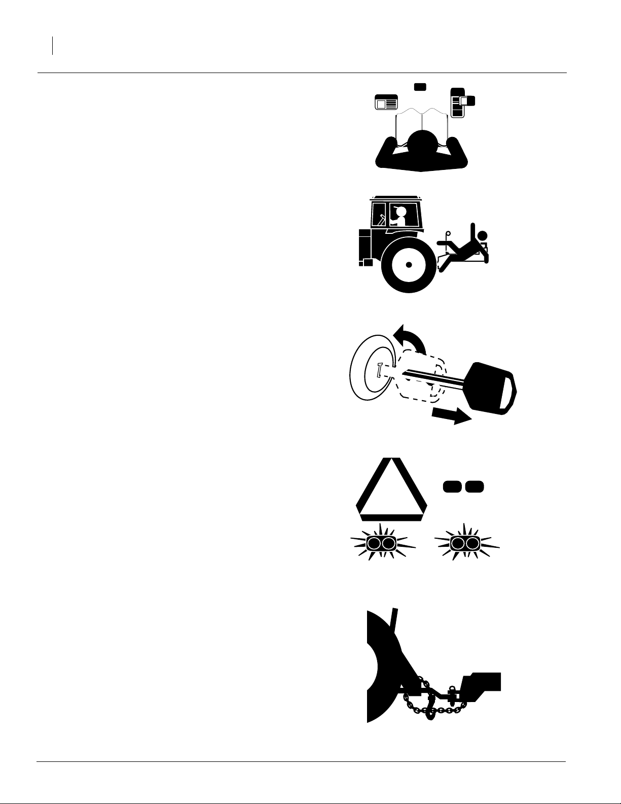
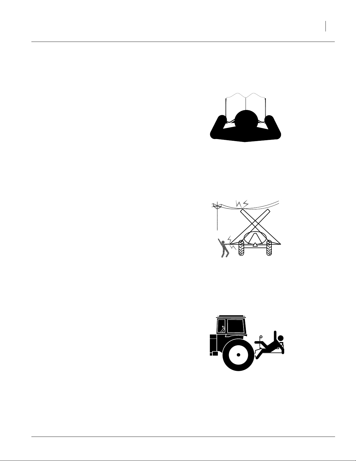
Keep Riders Off Machinery
Riders obstruct the operator’s view.Riders could
be struck by foreign objects or thrown from the
machine.
▲ Never allow children to operate equipment.
▲ Keep all bystanders away from machine dur-
ing operation.
Shutdown and Storage
▲ Fold sprayer booms, put tractor in park, turn
off engine, and remove the key.
▲ Secure Tandem Axle Sprayer using blocks
and supports provided.
OFF
▲ Detach and store Tandem Axle Sprayer in an
area where children normally do not play.
Use Safety Lights and Devices
Slow-moving tractors and towed implements can
create a hazard when driven on public roads.
They are difficult to see, especially at night.
▲ Use flashing warning lights and turn signals
whenever driving on public roads.
▲ Use lights and devices provided with imple-
ment.
Use A Safety Chain
▲ Use a safety chain to help control drawn
machinery should it separate from tractor
drawbar.
▲ Use a chain with a strength rating equal to or
greater than the gross weight of towed
machinery.
▲ Attach chain to tractor drawbar support or
other specified anchor location. Allow only
enough slack in chain to permit turning.
▲ Replace chain if any links or end fittings are
broken, stretched or damaged.
▲ Do not use safety chain for towing.
500-061M
3/18/2005
Page 5
Transport Machinery Safely
Maximum transport speed for implement is 20
mph. Some rough terrains require a slower
speed.Sudden brakingcan cause atowed loadto
swerve and upset.
▲ Do not exceed 20 mph. Never travel at a
speed which does not allow adequate control
of steering and stopping. Reduce speed if
towed load is not equipped with brakes.
▲ Comply with state and local laws.
▲ Do not tow an implement that, when fully
loaded, weighs more than 1.5 times the weight
of towing vehicle.
▲ Carry reflectors or flags to mark Tandem Axle
Sprayer in case of breakdown on the road.
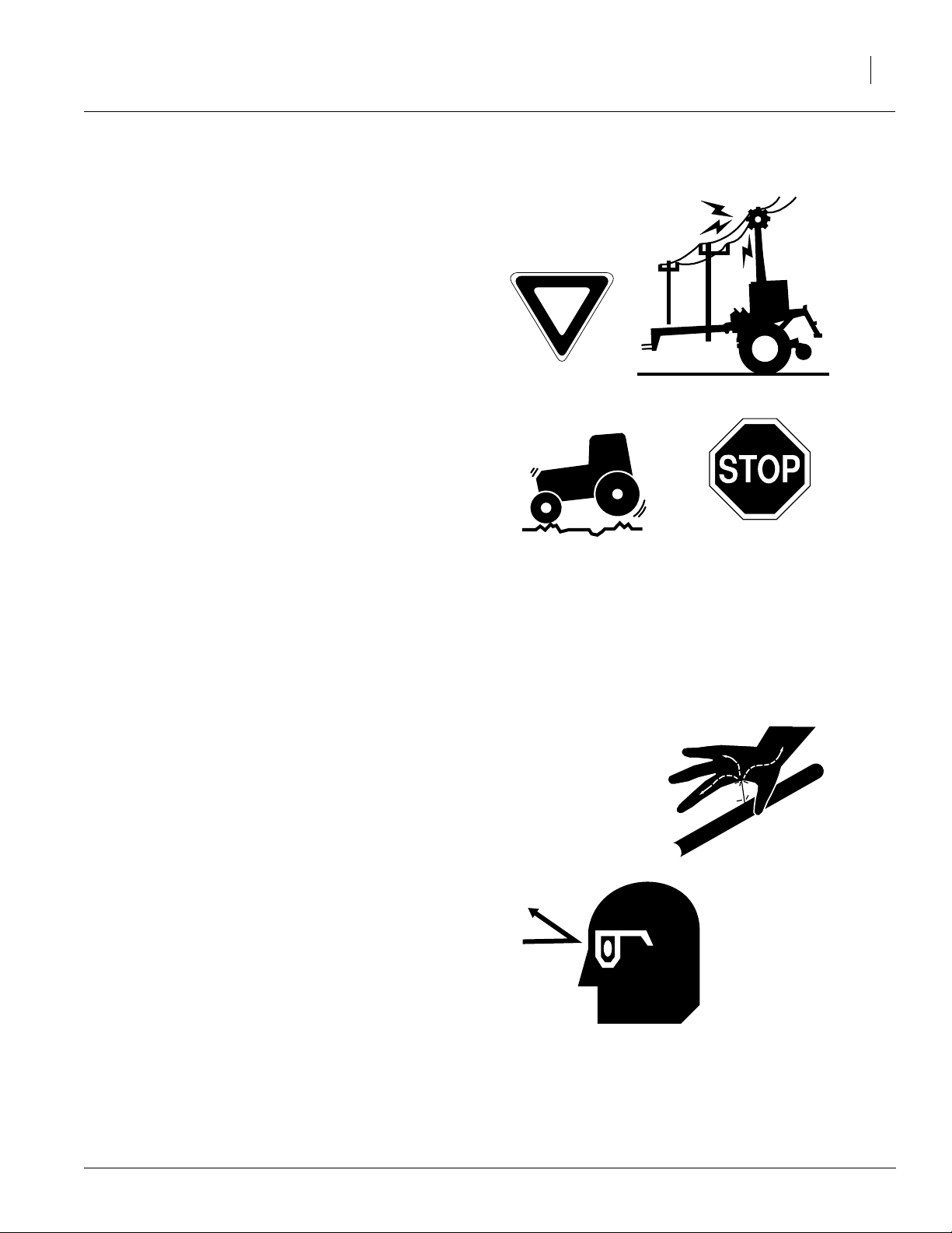
▲ Keep clear of overhead power lines and other
obstructions when transporting. Refer to transport dimensions under “Specifications and
Capacities,” page 61.
Important Safety Information
3
▲ Do not fold or unfold the Tandem Axle Sprayer
while the tractor is moving.
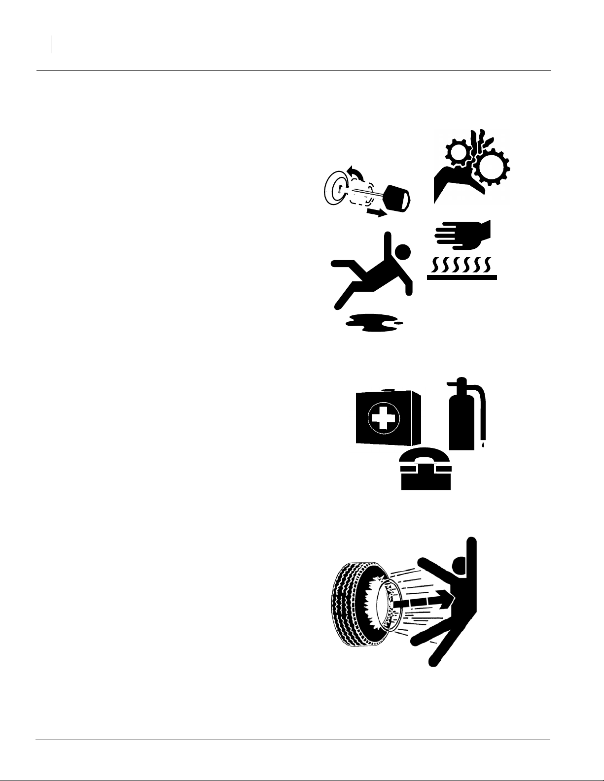
Avoid High Pressure Fluids
Escaping fluid under pressure can penetrate the
skin, causing serious injury.
▲ Avoid the hazard by relieving pressure before
disconnecting hydraulic lines.
▲ Use a piece of paper or cardboard, NOT
BODY PARTS, to check for suspected leaks.
▲ Wear protective gloves and safety glasses or
goggles when working with hydraulic systems.
▲ If an accident occurs, see a doctor immedi-
ately. Any fluid injected into the skin must be
surgically removed within a few hours or gangrene may result.
3/18/2005
500-061M
Page 6
1993-1995 Tandem Axle Sprayer
4
Practice Safe Maintenance
▲ Understand procedure before doing work. Use
proper tools and equipment. Refer to this manual for additional information.
▲ Work in a clean, dry area.
▲ Fold sprayer booms, put tractor in park, turn
off engine, and remove key before performing
maintenance.
▲ Make sure all moving parts have stopped and
all system pressure is relieved.
▲ Allow Tandem Axle Sprayer to cool com-
pletely.
▲ Disconnect battery ground cable (-) before
servicing or adjusting electrical systems or
before welding on Tandem Axle Sprayer.
▲ Inspect all parts. Make sure parts are in good
condition and installed properly.
▲ Remove buildup of grease, oil or debris.
▲ Remove all tools and unused parts from Tan-
dem Axle Sprayer before operation.
Prepare for Emergencies
▲ Be prepared if a fire starts.
▲ Keep a first aid kit and fire extinguisher handy.
OFF
▲ Keep emergency numbers for doctor, ambu-
lance, hospital and fire department near
phone.
Tire Safety
Tire changing can be dangerous and should be
performed by trained personnel using correct
tools and equipment.
▲ When inflating tires, use a clip-on chuck and
extension hose long enough for you to stand
to one side–not in front of or over tire assembly. Use a safety cage if available.
▲ When removing and installing wheels, use
wheel-handling equipment adequate for
weight involved.
500-061M
911
3/18/2005
Page 7

Wear Pr otective Equipment
Great Plains advises all users of chemical pesticides or
herbicides to use the following personal safety
equipment.
▲ Waterproof, wide-brimmed hat
▲ Waterproof apron.
▲ Face shield, goggles or full face respirator.
▲ Goggles with side shields or a full face respirator is
required if handling or applying dusts, wettable powders, or granules or if being exposed to spray mist.
▲ Cartridge-type respirator approved for pesticide
vapors unless label specifies another type of respirator.
▲ Waterproof, unlined gloves. Neoprene gloves are
recommended.
Important Safety Information
5
▲ Cloth coveralls/outer clothing changed daily; water-
proof items if there is a chance of becoming wet with
spray
▲ Waterproof boots or foot coverings
▲ Do not wear contaminated clothing. Wash protective
clothing and equipment with soap and water after
each use. Personal clothing must be laundered separately from household articles.
▲ Clothing contaminated with certain pesticides must
be destroyed according to state and local regulations. Read chemical label for specific instructions.
▲ Wear clothing and equipment appropriate for the job.
Avoid loose-fitting clothing.
▲ Prolonged exposure to loud noise can cause hear-
ing impairment or loss. Wear suitable hearing protection such as earmuffs or earplugs.
▲ Avoid wearing radio headphones while operating
machinery. Operating equipment safely requires the
full attention of the operator.
3/18/2005
500-061M
Page 8

1993-1995 Tandem Axle Sprayer
6
Handle Chemicals Properly
▲ Read and follow chemical manufacturer’s
instructions.
▲ Wear protective clothing.
▲ Handle all chemicals with care.
▲ Agricultural chemicals can be dangerous.
Improper use can seriously injure persons,
animals, plants, soil and property.
▲ Inhaling smoke from any type of chemical fire
is a serious health hazard.
▲ Store or dispose of unused chemicals as
specified by the chemical manufacturer.
▲ Before adding chemical to the tank, make
sure tank is at least half full. Do not pour concentrate into an empty tank.
▲ Spray only with acceptable wind conditions.
Wind speed must be below 5 mph. Make sure
wind drift of chemicals will not affect any surrounding land, people or animals.
▲ Never wash out the sprayer tank within 100
feet of any freshwater source or in a car wash.
▲ Rinse out the tank. Spray rinse water on last
field sprayed.
▲ Never leave fill hose attached to the sprayer
after filling tank. Chemicals in tank can siphon
out of tank and contaminate freshwater
source.
▲ Always keep hand-wash tank filled with clean
water and have soap available in case of an
emergency. Immediately and thoroughly flush
any area of the body that is contaminated by
chemicals.
▲ Do not touch sprayer components with mouth
or lips.
▲ If chemical is swallowed, carefully follow the
chemical manufacturer’s recommendations
and consult with a doctor.
▲ If persons are exposed to a chemical in a way
that could affect their health, consult a doctor
immediately with the chemical label or container in hand. Any delay could cause serious
illness or death.
▲ Dispose of empty chemical containers prop-
erly. By law rinsing of the used chemical container must be repeated three times. Puncture
the container to prevent future use. An alternative is to jet-rinse or pressure rinse the container.
▲ Wash hands and face before eating after
working with chemicals. Shower as soon as
spraying is completed for the day.
500-061M
3/18/2005
Page 9
Safety At All Times
Thoroughly read and understand the instructions
in this manual before operation. Read all instructions noted on the safety decals.
▲ Be familiar with all Tandem Axle Sprayer func-
tions.
▲ Operate machinery from the driver’s seat only.
▲ Do not leave Tandem Axle Sprayer unat-
tended with tractor engine running.
▲ Do not dismount a moving tractor. Dismount-
ing a moving tractor could cause serious injury
or death.
▲ Do not stand between the tractor and Tandem
Axle Sprayer during hitching.
▲ Keep hands, feet and clothing away from
power-driven parts.
Important Safety Information
7
▲ Wear snug-fitting clothing to avoid entangle-
ment with moving parts.
▲ Watch out for wires, trees, etc., when folding
and raising booms Tandem Axle Sprayer.
Make sure all persons are clear of working
area.
▲ Do not turn tractor too tightly, causing Tandem
Axle Sprayer to ride up on wheels. This could
cause personal injury or equipment damage.
▲ Use only water without pesticides added to
calibrate the sprayer.Do not exceed the calibrated sprayer speed and pressure when
operating.
▲ When using a PTO pump, be sure that PTO
shield is in place on the tractor, PTO coupler
bolts are torqued to the correct specification,
and torque bar is properly chained to tractor
drawbar.
▲ Spray with the boom in the unfolded position
only.
▲ The boom has many pinch points during field
operation and folding. Keep all bystanders
away.
3/18/2005
500-061M
Page 10
1993-1995 Tandem Axle Sprayer
8
Safety Decals
Your implement comes equipped with all safety
decals in place. They were designed to help you
safely operate your implement.
▲ Read and follow decal directions.
▲ Keep all safety decals clean and legible.
▲ Replace all damaged or missing decals. Order
new decals from your Great Plains dealer.
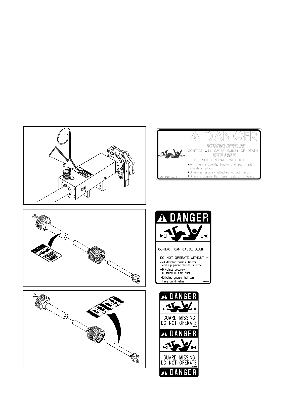
Refer to this section for proper decal placement.
ROTATING DRIVELINE
KEEP AWAY!
12555
▲ When ordering new parts or components, also
request corresponding safety decals.
▲ To install new decals:
1. Clean the area where the decal is to be
placed.
2. Peel backing from decal. Press firmly on
surface, being careful not to cause air
bubbles under decal.
818-142C
Danger! Rotating Driveline Entanglement Hazard
12558
12557
500-061M
ROTATING DRIVELINE
KEEP AWAY!
383333
Danger!Rotating Driveline
Entanglement Hazard
383334
Danger! Rotating Driveline Entanglement Hazard. Guard
Missing DO NOT Operate
3/18/2005
Page 11
12221
Important Safety Information
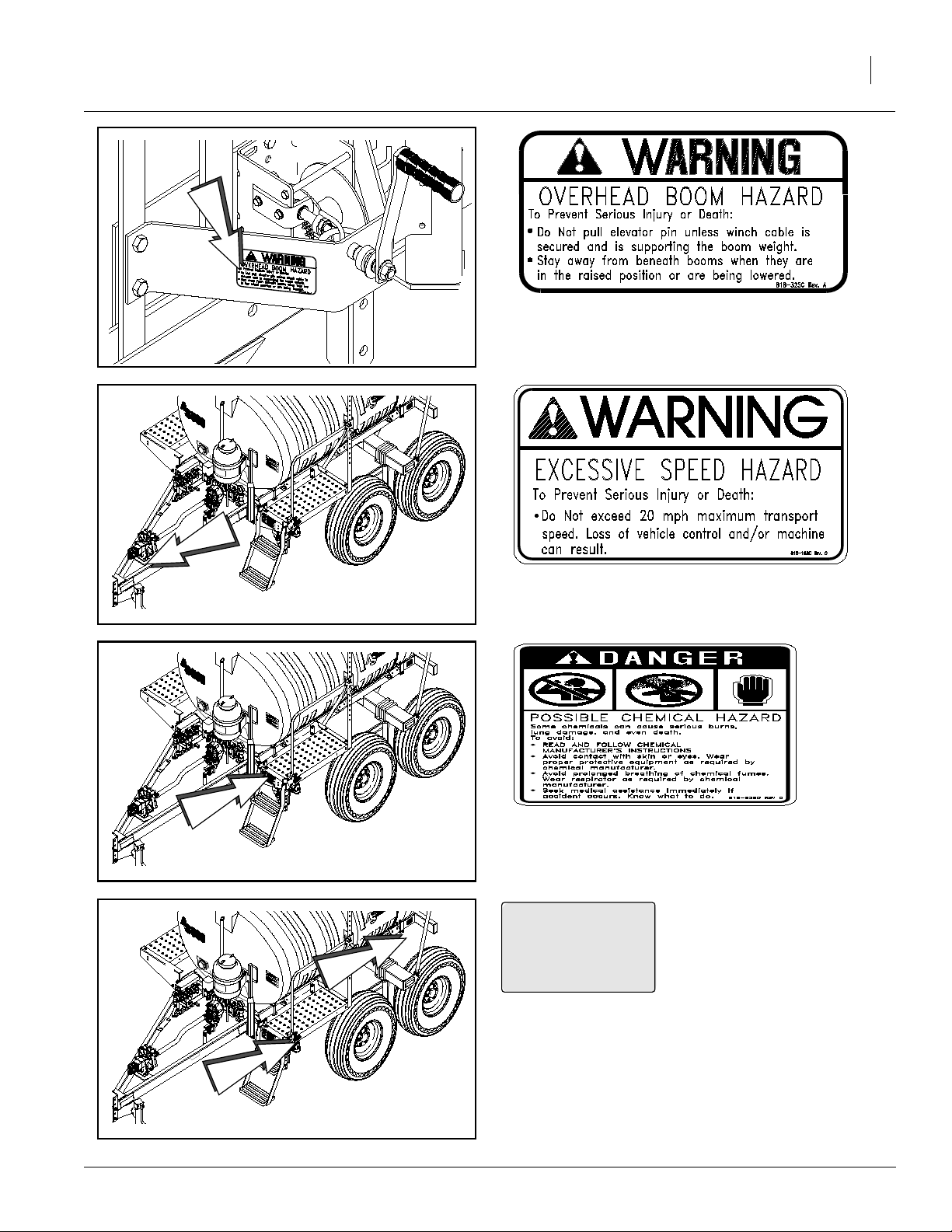
818-325C
Caution! Secure Winch Cable
9
13523
13523
818-188C
Warning! 20 mph maximum transport speed.
818-323C
Caution!Useproper personal safety equipment. Also, refer to previous page.
3/18/2005
13523
818-229C
Amber Reflector {Both Sides on both locations}
500-061M
Page 12
1993-1995 Tandem Axle Sprayer
10
13523
13523
818-324C Stainless Steel Tank Only
Caution! General Sprayer Safety Information.
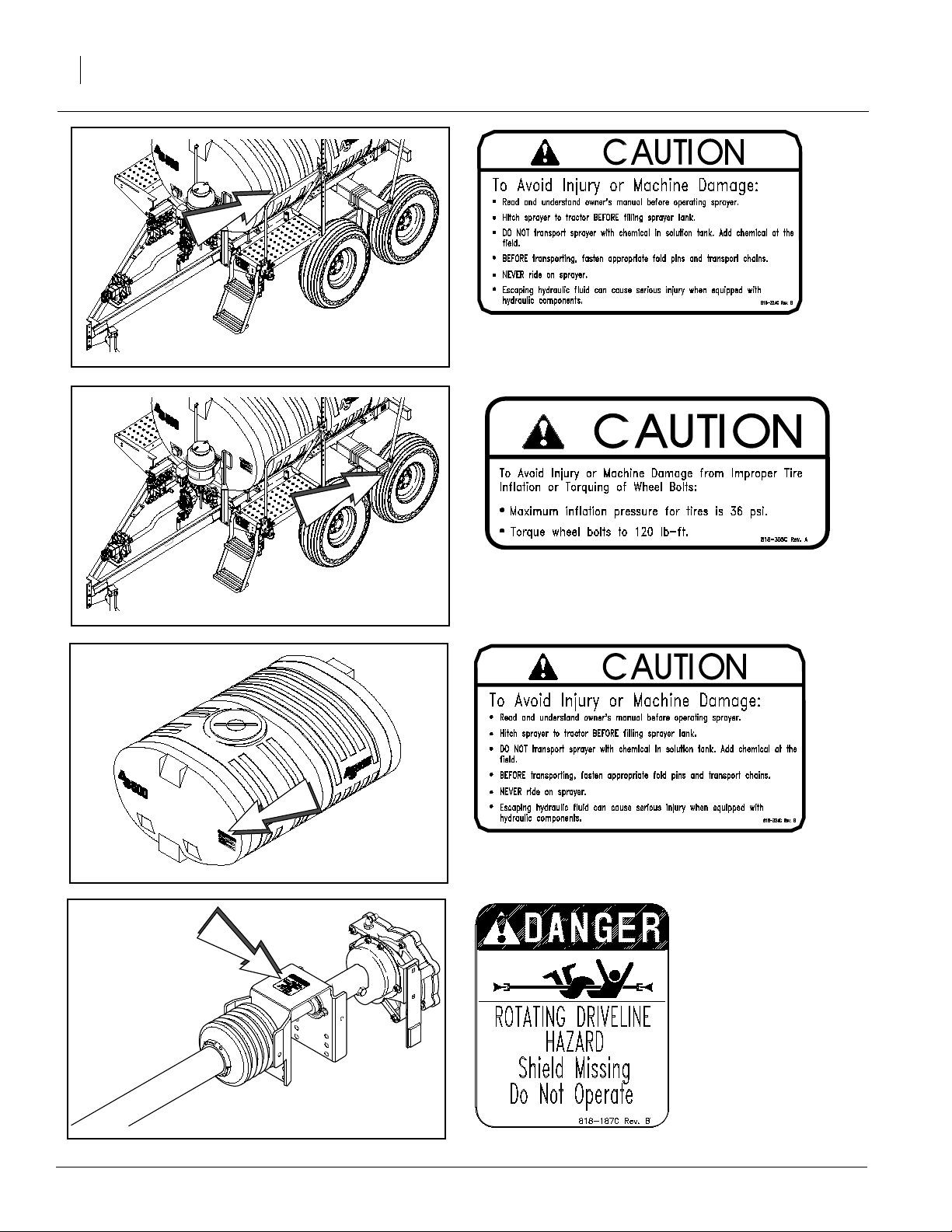
818-305C
Caution! Tire inflation & wheel bolt torquing information.
500-061M
12220
12556
818-324C Polyethylene Tank Only
Caution! General Sprayer Safety Information.
818-187C
Danger! Rotating Driveline Hazard
3/18/2005
Page 13
ROTATING DRIVELINE
KEEP AWAY!
13033
Important Safety Information
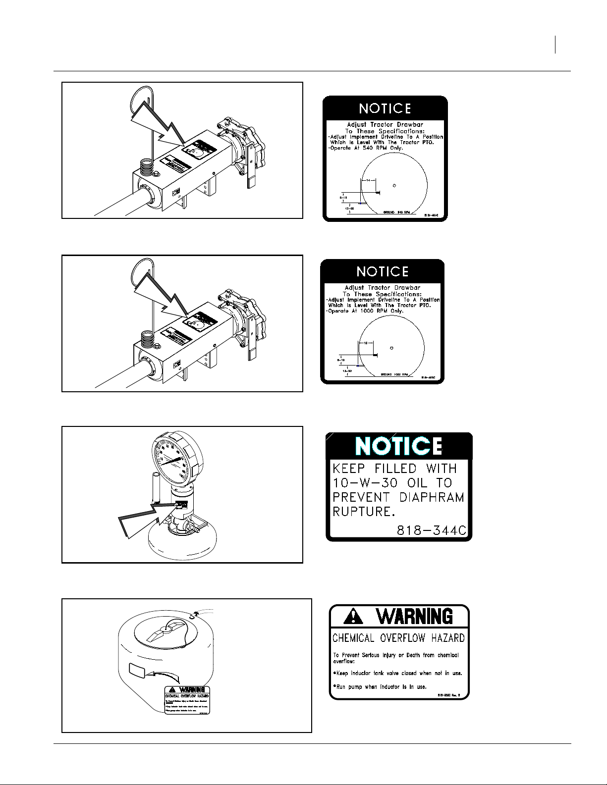
818-464C
Notice - Driveline AttachmentSpecifications{540
rpm PTO only}
11
ROTATING DRIVELINE
KEEP AWAY!
12219
13036
818-465C
Notice - Driveline Attachment Specifications {1000
rpm PTO only}
818-344C
Notice - Keep
filled with 10-W30 oil to prevent
diaphragm
rupture
3/18/2005
12164
818-303C
ChemicalInductor
Tank Warning
500-061M
Page 14

1993-1995 Tandem Axle Sprayer
12
Introduction
GreatPlains welcomesyouto itsgrowingfamilyof
new product owners. This Tandem Axle Sprayer
has been designed with care and built by skilled
workers using quality materials. Proper setup,
maintenance and safe operating practices will
help you get years of satisfactory use from the
machine.
Description of Unit
The Tandem Axle Sprayer is a pull type sprayer.
Intended Usage
Use this pressurized sprayersystem to apply liquid pesticides, herbicides or fertilizers to
production-agriculture crops only. Do not modify
sprayerforuse with attachments other than those
approved by Great Plains.
Models Covered
1993-1995 Tandem Axle Sprayer
Using This Manual
This manual will familiarize you with safety, assembly, operation, adjustments, troubleshooting
and maintenance. Read this manual and follow
the recommendations to help ensure safe and efficient operation.
The information in this manual is current at printing. Some parts may change to assure top
performance.
Definitions
The following terms are used throughout this
manual.
Right-hand and left-hand as used in this manual
are determined by facing the direction the machine will travel while in use unless otherwise
stated.
IMPORTANT: A crucial point of information related to the preceding topic. For safe and correct operation, read and follow the directions
provided before continuing.
500-061M
NOTE: Useful information related to the preceding topic.
3/18/2005
Page 15

Owner Assistance
If you need customer service or repair parts, contact a Great Plains dealer. They have trained
personnel, repair parts and equipment specially
designed for Tandem Axle Sprayerproducts.
Yourmachine’spartswerespecially designedand
should only be replaced with Tandem Axle Sprayerparts. Alwaysuse the serial and model number
when ordering parts from your Great Plains
dealer.
Record your model and serial number here for
quick reference:
Model Number:__________________________
Serial Number: ___________________________
Introduction
13
Your Great Plains dealer wants you to be satisfied
with your new machine. If you do not understand
anypartof thismanual orare not satisfiedwith the
service received, please take the following
actions.
1. Discuss the matter with your dealership service manager. Make sure they are aware of
any problems so they can assist you.
2. If you are still unsatisfied, seek out the owner
or general manager of the dealership.
3. For further assistance write to:
Product Support
Great Plains Mfg. Inc., Service Department
PO Box 5060
Salina, KS 67402-5060
3/18/2005
500-061M
Page 16

1993-1995 Tandem Axle Sprayer
14
Before You Start
Readandunderstand the owners manual foryour sprayer. A basic understanding of how the sprayer works will
aid in the assembly,setup and operation of yoursprayer.
Perform these checks before setting up your Tandem
Axle Sprayer.
1. Read and understand “Important Safety Information,” beginning on page 1.
2. Check that all working parts are moving freely,bolts
are tight, and cotter pins are spread.
3. Check that all grease fittings are in place and lubricated. Refer to “Lubrication,” page 56.
4. Check that all safety decals and reflectors are correctly located and legible. Replace if damaged. Refer to “Safety Decals,” page 8.
Tractor Requirements
To operate your Great Plains Sprayer,a tractor using a
12 volt electrical system must be used.
The tractor will need two hydraulic outlets (one pair) if
the sprayer is equipped with a hydraulic pump.
Before You Start
Readandunderstand the owners manual foryour sprayer. A basic understanding of how the sprayer works will
aid in the assembly,setup and operation of yoursprayer.
Before attempting to assemble the sprayer,use the following as a checklist. Having all the needed parts and
equipment readily at hand will speed up your assembly
task and will make the job as safe as possible.
1.❑Check for all sprayer components and hardware.
2.❑Ifabolt, pin or other component has been removed,
or if you are unsure about where it is used, refer to the
parts section of this manual to identify it.
500-061M
3/18/2005
Page 17
Preparation and Setup
Preparation and Setup
15
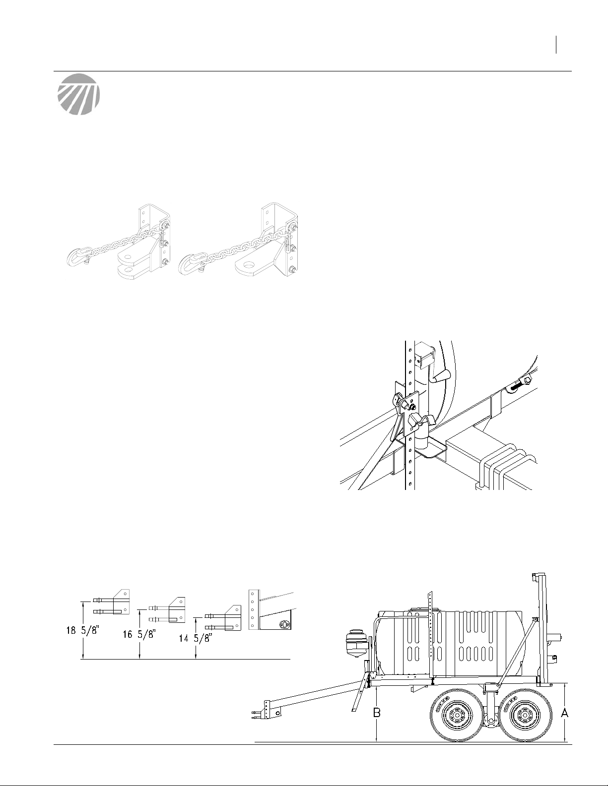
Tractor / Sprayer Hook-Up Instructions
Refer to Figure 1
The GreatPlainsTandem Axle Sprayeris equipped with
either a clevis style hitch, or a single tang hitch.
11568
Figure 1
Clevis Style Hitch Single Tang Hitch
Refer to Figure 2
1. Park the sprayerin an open,flat area with the jack in
the park position. Using a tape measure, check the
distancefrom the frontunder side ofthe frame tothe
ground and the back under side of the frame to the
ground. Adjust the jack so that dimension "A" is
11/2inchesgreaterthan dimension "B". The goal is
to have the solution drain into the sump of the tank
so there is no excess solution in the tank when
drained.
11569
4. Hitch the sprayer to the tractor using a hitch pin of
adequate strength (minimum 1 inch diameter). You
must also install a retaining clip on the hitch pin to
preventit from coming out and causing a chemical
spill.Retractthejackuntil theweight istransferredto
the hitch.
5. Recheck to see that the frame is sloping downward
in the front with dimension “A" being approximately
1 1/2 inches greater than dimension “B”.
6. Your Sprayer comes equipped with a hitch safety
chain.The safetychain should be securelyattached
to the sprayer hitch and the tractor drawbar support
whenevertowing or spraying.
Refer to Figure 4
7. Unpin the tongue jack, and pin it in the transport position.
2. Back the tractor draw bar up to the sprayer hitch to
determine the amount of adjustment needed.
Refer to Figure 3
3. The mounting holesin the hitch havethreepositions
that it can be located. Movethe sprayerhitch height
to the height of your tractor’sdrawbar and bolt the
hitch onto the sprayermaking sure to torque the
bolts to the correct specification on the “Torque Val-
ues Chart” on page 62. The single tang hitch has
the same height adjustment as the clevis hitch.
11582
Figure 3
Hitch Height Adjustment
Figure 2
Frame Hook-Up Height
11529
Jack In Transport Position
Figure 4
Note: When hitching the sprayer to a different tractor,
check for a difference in drawbar heights. If the heights
aredifferent, the hitchheight must be readjusted accordingly.
11581
3/18/2005
500-061M
Page 18

1993-1995 Tandem Axle Sprayer
16
Tractor / PTO Pump Hook-Up
1. Position the PTO pump on the tractor’s PTO shaft
with the coupler bolt loose on the splined end.
2. Push the coupler of the pump on to align with notch
in the tractor PTO shaft and install bolt.
3. Make sure there is adequate hose length to reach
the pump.
4. If youhavea 540rpmpump ora 1000rpm1 3/8 inch
spline pump, torque the 1/2 inch Grade 8 coupler
bolts to 105 ft-lbs. If you havea 1000 rpm 1 3/4 inch
spline PTO pump, torque the 5/8 inch Grade 8 coupler bolt to 210 ft-lbs and the other 1/2 inch Grade 8
coupler bolt to 105 ft-lbs.
5. Rotate thePTOshaft byhand tomake surethe bolts
clear the PTO shielding.
6. Attach the torque bar chain to the drawbar securely.
7. Hook the tarp strap in such a way that the slack in
the chain is taken up slowly when the PTO is engaged so the torque bar does not bang.
8. Tie up any loose hoses with cable ties to prevent
hose damage.
Tractor / Hydraulic Pump Hook-Up
1. Yourtractor should be equipped with at least two remote outlets (one pair).
2. If your tractor has an open-center hydraulicsystem,
remove the orifice restrictor in the pressure line. If
your open-center hydraulic system produces more
than15 GPM, it isnot recommended to hookthis hydraulic pump up to your tractor.The pump will spin
too fast. If your open-center hydraulic system is 15
GPMor less,itis recommendedto installa hydraulic
flow divider so that you can adjust the speed of the
pump. A Gresen model number CFDA or similar
flow divider will work. The maximum flow for the hydraulic motor is 6 GPM.
4. If your tractor has a closed-center system, or a flow divider has been installed in your tractor’s open-center
system, set the hydraulic flow control valve at a minimum flow for the pair of outlets that operates the
pump.
5. With water in the sprayertank, and water in the pump,
place the hydraulic lever in the float position and start
the tractor.
6. Place a stop in the neutral position of your tractor hydraulics so that the lever can only be moved to the
float and down positions. Refer to your tractor operator’s manual or tractor dealer on information for the
neutral stop.
IMPORTANT: DO NOT move the h ydr aulic lever into
the neutral position while the hydraulic pump is running. To do so may cause damage to the hydraulic
pump.
7. To set the hydraulic flow control on the tractor,first engage the pump by placing the hydraulic leverin the
down position. Once the system builds pressure,
close the agitation valve,shut off the boom section
switches and close throttling valves {if applicable}.
Sprayerswith RavenAutomatic Monitors do not have
throttling valves.The pump is now at dead head pressure.Adjust thehydraulic flowcontrol valvesothat the
spray pressure reaches 80 PSI maximum on the nozzlepressure gauge. If so equipped, reset the solenoid
throttling valves as described in the "Solenoid Throt-
tling Valve" on page 51.
3. For the hydraulic motor to turn in the right direction,
thepressure hosemust beconnected tothe "A"port
ofthe motor and the return line connected to the "B"
port. Install hydraulic hose clamp label provided {refer to hydraulic pump section in parts manual} approximately18inches fromtractor quickcouplersso
that the hydraulic cylinder retract symbol and arrow
aligns with the pressure hose going to motor port
"A". If your tractor is a John Deere, leave the restrictor in the pressure side ofthehydraulicpump.If
your tractor has a closed center hydraulic system
and is not a John Deere, remove the restrictor.
500-061M
3/18/2005
Page 19
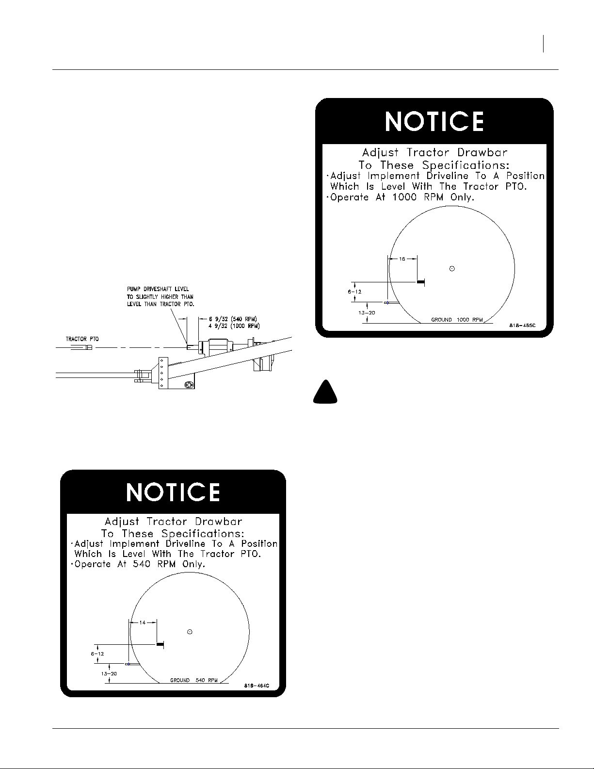
Tractor / PTO Shaft Hook-Up
Refer to Figure 5
1. PositionPTOshafton tractor.Be sure shaft iscoupled
on tractor.
2. Adjust the vertical position of the pump driveshaft on
thesprayerso that it is level,to slightly higher than level with the PTOshaft on the tractor as shown. This reduces driveline vibration when turning a corner.
Adjust the vertical position by moving the four bolts
supporting the driveshaft bracket.
Note: If, after adjusting the vertical position of the pump
driveshaft, you find that the driveshaft is still a lot higher
than the PTO driveshaft on the tractor; adjust the hitch up
one position and readjust the pump driveshaft. Refer to
"Tractor/Sprayer Hook-Up Instructions" starting on
Page 15 to adjust the hitch.
Preparation and Setup
17
13524
Figure 5
Hitch Height Adjustment
Refer to Figures 6 and 7
3. The shaft height and length should be assembled to
ASAE standard or as described.
Figure 7
Tractor Drawbar Adjustment {1000 rpm only}
!
WARNING
Keep all shields in place.
4. Keep all shields in place for your safety
5. Be sure PTO shaft support is swung out of the way
and pinned before operating.
Wheel Width Adjustments
You may need to adjust the wheel width on your Great
Plains Sprayer to match the row widths for row crops. To
adjust the wheel spacing proceed with the following:
1. Park the sprayer in an open, flat area and unfold the
boom.
2. Drain the sprayer tank of any excess water or chemical. Never park the sprayer tank that has been exposed to chemicals within 100 feet of a freshwater
source.Disposeof chemicalproperly byinstruction on
the chemical label.
3/18/2005
3. Put blocksonthe front and rear side of the tires on the
left side of the sprayer.
4. Loosen the u-boltsof the axle notsupported byblocks
on the right side but DO NOT loosen the nuts completely.
Figure 6
Tractor Drawbar Adjustment {540 rpm only}
500-061M
Page 20
1993-1995 Tandem Axle Sprayer
18
5. Jackup the frame abovethe right axlewitha hydraulic
jack or hoist.
6. Loosen the u-bolts and slide the tandem axle assembly to the desired position.
7. Tighten the u-bolts until they are snug.
8. Let theframe downuntil thewheels aresupporting the
weight.
9. Torque down the u-bolt nuts according to the "Torque
Values Chart" on page 62.
10. Repeat steps 3 through 9 for the left side.
Quad-Jet Agitators {Stainless Steel
Tanks Only}
Refer to Figure 8
The Quad-Jet agitators are the two agitators in the stainlesssteel tank. Each agitatorhas four holesthat shoot jets
ofwaterout atahigh velocity. Theagitator headis oriented
at 45 degrees, with reference to the tank ends, so that the
water jets are aimed at the corners of the tank. To ensure
proper agitation, make sure that the agitator heads are always kept in the orientation as shown.
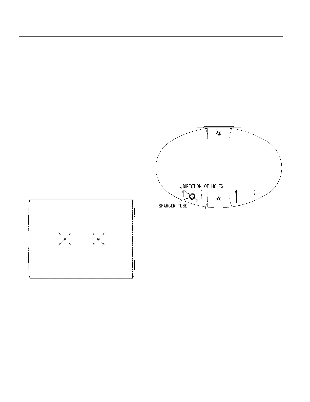
Sparger Tube Agitators {Poly ethylene
Tanks Only}
Refer to Figure 9
The sparger tube is used to agitate the liquid in the polyethylene tank. It has a line of holes in the tube that
produces water jets at even intervals in the tank. These
waterjetsare oriented ina waythatcauses theliquid inthe
tank to “roll”. Below shows an end view of the front of the
poly tank with an arrow showing the direction that the water shoots out of the sparger tube. Make sure that the
water jets are oriented as shown to ensure proper
agitation.
Figure 8
Tank Top View
Quad-Jet Agitator Head Orientation
11584
Figure 9
Tank End View Sparger Tube Orientation
11585
500-061M
3/18/2005
Page 21

Preparation and Setup
19
Control Bo x Assemb l y {Man ual Control Systems Only}
Refer to Figure 10
1. Remove the solenoid cover to gain access to the solenoid terminals.
2. Mount the control boxon yourtractor.Connect the red
wire (1) to the positive terminal of the 12 volt battery
andthe white wire(2) to thenegative terminal. You will
need to pull the red and white wires out of the black
harness (3) until there is enough wire to reach the battery.
Note: You may want to attach the battery leads (4) to the
battery terminals and the control box power leads so that
the control box can be disconnected easily.
Afterthe powerleads (1) and(2)are hookedto the battery,
you should be able to turn on the master switch and see
the red power light come on. Turn the master switch OFF
BEFORE proceeding to the next step.
3. Attach the electric solenoid cord (5) to the solenoids
as shown. The green wire attaches to the front solenoid {front being toward the hitch}. The yellow wire attaches to the middle solenoid and the brown wire
attaches to the rear solenoid. Connect the other wire
{white} to all three solenoids.
7. Reassemble the solenoid coverover the top of the solenoids.
4. Hook up the electric solenoid cord (5) to the solenoid
plug (6). You may need to use the extension cord included to reach the solenoid valves more easily.Turn
the master switch on and flip the boom section switches to see if the solenoids are operating properly. The
leftboom switchshould operatethe front solenoid,the
center boom switch should operate the middle solenoid, and the right boom switch should operate the
rear solenoid. If the switches don’t correspond with
the correct solenoids, checkyourelectric cord assembly in Step 3, or the wiring of the control box under
"Control Box Wiring Assembly Instructions"on
page 20.
5. Attach the electric ball valve cord (7) to the terminals
(8) on the electric ball valve.
6. Hook up theelectricball valvecord (7)tothe ball valve
plug (9). You may need to use the extension cord included to reach the ball valve. Turn the master boom
switch and flip the pressure adjust switch. The ball
valve should operate when the switch is flipped.
13040
Figure 10
Control Box Assembly
Automatic Contr oller Monitor
To assemble the Raven 440 Control system on the sprayer, refer to the Raven 440 owner’s manual.
3/18/2005
500-061M
Page 22

1993-1995 Tandem Axle Sprayer
20
Control Bo x Wiring Assemb l y
Instructions {Manual Control System
Only}
Refer to Figure 11
The electrical assembly schematic is shown for the control box in a view that is looking into the back of the box
with the cover off. There are four separate wiring harnesses that enter into the control box along with the
positive and negative power leads. In this control box,
thered wires are alwayspositive and the whitewiresare
always negative. Other colored wires could be positive
or negative. Make sure that all wires are attached as
shown in the schematic. There are two wire nuts that at-
tachseveralwires atonce and aredisplayedby thelarge
asterisk (*) signs in the drawing.
Attach the wires as shown in the drawing for any electrical repair work. This will also serve as a guide for
replacing the electrical wiring. Refer to "Sprayer Con-
trol Box Assembly" in the parts manual.
IMPORTANT: Disconnectbattery leadsbefore
working on any electrical components in this control
box. Failure to do so may result in damage to the
electrical components.
500-061M
11473
Figure 11
Control Box Wiring Assembly
3/18/2005
Page 23

Operating Instructions
Operating Instructions
21
Basic Sprayer Operating
Procedures
1. Make sure to read the label on the chemical compound that is to be applied. It is the law.
2. Consider how the chemical will be stored and how
you will dispose of the chemical, according to the
chemical label.
3. When calibrating, filling the tank, or working around
chemicals, wear protective clothing that covers the
body. Refer to "Personal Safety Equipment"on
page 5. Have soap and clean water availableto
wash any exposed areas. Never open a container
with your bare hands.
4. When filling the sprayer, it is better to mix the chemical in the field where it is to be applied. Position the
sprayer100 feetfrom any well or other water source
BEFORE mixing chemical.
5. By law,you must repeat the rinsing of the chemical
container 3 times. The container should then be
punctured to preventfuture use. An alternative is to
jet-rinse or pressure rinse the container.
11. Take note of adjoining crops, houses, gardens, people, etc.
12. When youarefinished spraying,emptythe tank and
flush the sprayerwith water,including the pump,the
nozzles and the bypass line from the solenoids.
Properlystore thechemical emptiedfrom thetank or
dispose of it by the recommendations on its label.
13. When turning at the end of a field, make sure you
are correct on the rows so that the boom will not
overlap on crop previously sprayed.
6. Check the condition of hoses and connections frequently. Release system pressure BEFORE working on the sprayerby shutting off the pump and
flipping the individual boom section switches on the
control box. ALWAYS wear rubber gloves when
making repairs or adjustments.
7. After unfolding the boom, remove the level float pin
and place in the storage position. Refer to your
Great Plains Boom Manual for more information.
Note: If possible, do not operate your Great Plains
SprayerBoom without first unlocking the level-floatpin.
Theboom will float overthe contoursof the ground more
effectivelyand minimize stress on the boom.
8. Apply spray when the wind is 5 m.p.h. or less. Minimize drift by using nozzle tips with the largest practicalopeningsandbyoperating the sprayerboom at
the lowestpractical height and lowest practical pressure.
9. Drive at the same speed you used in your calibration. Refer to "Sprayer Calibrations" on page 28.
Keep your sprayer calibrated.
10. If possible work crosswise to the wind, starting from
the downwind side of the field. Do this so you won’t
everbe heading directly into chemical fumes.
3/18/2005
500-061M
Page 24

1993-1995 Tandem Axle Sprayer
22
Plumbing Operations {Manual Control System Only}
The basic plumbing diagrams are shown for both the
stainless steel tank sprayerand the polyethylene tank
sprayer. A basic knowledge of how the sprayeris
plumbed will help youto understand how to operate you
Great Plains Sprayer. Throughout this manual, the components on this diagram will be described with the
terminology labeling these components. For further details about the plumbing components, refer to the parts
manual.
1. Fluid is drawn out of the sump in the tank and passes through the pump. From the pump it passes
through the solution whirlfilter®and filters out or
grinds up all undissolved chemical and solid particles.The fluidthen passesthroughthe agitationball
valve or proceeds through the electric pressure adjustment ball valve. If the fluid passes through the
electric ball valve,it proceeds to the 3-way solenoid
valves.If a solenoid valve is on, the fluid passes to
its perspective boom section and is sprayedout the
individual nozzles. If that solenoid is off,the fluid bypasses back into the pump inlet.
Plumbing Diagrams Stainless Steel Tank
11500
{Manual Control System Only}
You can monitor the nozzle pressure gauge and adjust the pressure to the booms by adjusting the
pressure switch on the control box. The pressure
switch rotates the electric ball valve.To decrease
thesensitivity of the pressure adjustment switchthe
manual pressure adjustment valvemust be set. To
set this valve, run the pump at the same rpm you
would when spraying. Open the electric ball valve
completely and adjust the manual pressure adjustment valvedown so that the nozzle pressure gauge
reads10to 20 psi greater than the pressure you will
sprayat.This will decreasethe amountof flowtothe
electric ball valve and reduce its sensitivity.
Note: When pressure is increased at a later date, the
manual pressure adjustment valvewill need to be
opened.
The agitation can be set by adjusting the agitation pressure valve while the pump is at operating speed. Adjust
thevalveuntil youget thedesiredagitation pressureyou
would like on the agitation pressure gauge.
There are tank shut off valves everywhere there is an
outlet from the tank so that if there is a leak, the source
can be shut off and the chemical spill reduced. These
valvesneed to be wide open when the sprayeris in use.
Plumbing Diagrams Polyethylene Tank
11501
{Manual Control System Only}
500-061M
3/18/2005
Page 25

Operating Pump
To operatethe PTOpumps,engage the PTO shaft slowly at the tractor’sidle throttle position. Slowly accelerate
to the desired PTOrpm (On a 540 rpm pump it is recommended to operate the pump at 540 rpm and on a 1000
rpm pump it is recommended to operate the pump at
1000 rpm). Disengage the PTO at any rpm to stop the
pump.
!
WARNING
Never operate the PTO pump without the pump tongue bar
firmly chained in place. Neveroperate the PTO pump without
the tractor PTO shield in place for both the PTO and PTO
driveline pumps.
Operating Instructions
!
CAUTION
Do not add the chemical until you areat the field, just prior to
spraying. When you add the chemical, follow the manufacturer’s instructions for mixing the spray solution in order to
achieve the desired application rate.
!
CAUTION
Read the manufacturer’s label carefully before handling
chemicals.
3. Before you add the chemical to the tank, make sure
the tank is at least one half full. The concentrate
should not be poured into an empty tank.
23
To operate the hydraulic pump, first make sure that the
hydraulic hoses are routed correctly so that the pump
turns in the correct direction. See the “Tractor/Hydrau-
licPump Hook-Up”on page 16, formore details.Torun
the pump, push the hydraulic lever in the “down” position. When you want to stop the pump, push the
hydraulic lever in the “float” position.
IMPORTANT: Do not move the hydraulic lever to the
neutral position while the hydraulic pump is running.
To do so may cause damage to the hydraulic pump.
Filling Tank Procedures
!
CAUTION
Whenfilling thesprayer tank, use a checkvalve or anti-siphon
device to prevent the solution in the tank from infiltrating into
the fresh water source and contaminating it.
Your Great Plains Sprayer fills the tank from the bottom
of the tank and uses a standard 2 inch Cam-Lock coupler to connect to the freshwater hose. An 1 1/2 inch
camlockcoupler isalsoavailableas an accessory.Refer
to "Quick Fill Assembly" in the parts manual.
4. Keep the spray solution away from all skin. Wear
protective clothing and goggles. If the solutions
comes in contact with the body, wash off the contaminated area with soap and water.
5. Keep chemical containers low when pouring.
6. Let the wind blow fumes and dust away from you
while pouring the chemical.
7. DO NOT smoke while handling chemicals.
Using Handwash Tank
In the event when an accident occurs and chemical is
spilled on your skin or in your eyes, use the Handwash
Tank to flush away the chemical.
1. Open the tank valve and use the hose to direct the
clean water on all contaminated areas. Wash all areas of skin that has been contaminated with soap
and water. To flush your eyes, point the hose and
water stream upward while you lower your eye into
the stream of flowing water.
2. Close the tank valve and refill the handwash tank
with fresh water when you are finished.
3. Periodically refill the handwash tank with fresh water. ALWAYS keep the handwash tank clean.
1. To fill the tank, hook up the freshwater hose to the
quick-fillcamlockcoupler withthequick-fillballvalve
in the closed position.
2. Turn the water on and open the quick-fill ball valve
for the freshwater to enter the tank. When using a
positivedisplacement pump to fill the tank, open the
quickfill ball valve first and then pump waterinto the
tank.
3/18/2005
500-061M
Page 26

1993-1995 Tandem Axle Sprayer
24
Operating Whirlfilter
®
Thereare twoWhirlfilters®onyourGreat Plains Sprayer.
One filters the water entering the tank and the other filters the chemical solution being sprayed.
To clean-out the solution Whirlfilter
®
, proceed with
the following:
1. Fill the sprayer tank with water and turn the pump
on.
2. With the pump running, slowly open the clean-out
valve and allow the grit to flow out into a bucket.
Clean out the solution Whirlfilter®only when the
sprayertank is filled with waterand no chemical has
been added.
3. Close the clean-out valve and turn off the pump.
4. Dispose of the grit and water in the same manner
described on the manufacturer’s label of the latest
chemical used in the sprayer.
To clean out the tank-fill Whirlfilter®, proceed with
the following:
1. Start with an empty sprayer tank.
11566
Figure 12
Elevator Winch Illustration
2. Position a bucket under the plug in the sump of the
Whirlfilter®and allow the grit to fall out.
3. Screw the plug back in using pipe thread sealant to
seal the plug.
4. Dispose of the grit and water in the same manner
described on the manufacturer’s label of the latest
chemical used in the sprayer.
Manual Elevator Option
Refer to Figure 12
1. Crank thewinch handle (3)clockwise1/4 ofa turn or
until the weight is supported by the cable
IMPORTANT! DO NOT crank the winch too far with
the lock pin locked. Todo so may break the cable or
damage the elevator.
2. After the weight is supported by the cable, you
should be able to pull the lock handle (1) out easily.
Pull the lockhandle out and leaveit sticking out with
the lock pin removed from the lock hole (2).
3. Crank the winch to the desired boom height.
Transporting
Refer to Figure 13
1. Park yoursprayerin an openarea where youwill not
hitpower lines,buildings,etc. when theboom is folded.
2. Secure the level-floatpin in the lock position.
12005
4. Push the lock handle down to lockthe pin into a lock
hole(2). Crankthe winchuntil the lockpinsnapsinto
the hole.
500-061M
Figure 13
Level Float Pin In Lock Position
3/18/2005
Page 27

Operating Instructions
25
Refer to Figure 14
3. Foldthe outer boomwings overandfasten theclevis
pin(1) into the foldposton both wings of the sprayer.
4. Fold the boom wings forwardand position theboom
wing on the fold latch. If the fold latch happens to be
positioned where a hose fitting or nozzle is, you will
need to reposition the extension latch with the carrier extension (3). Unbolt the carrier extension and
use it to reposition the fold latch. Discard the carrier
extension if not needed.
Adjust the fold latches vertically using the different
holespacings sothat when theelevatorpin islocked
you can fold the wings forward and the angled surfaceof the fold latch matches the boom tube. When
the fold latch isn’t adjusted properly the fold latch
maynot latch or the boom will try to come out of the
cradle when the fold latch lever (2) is released.
5. Position the fold latch lever (2) so that the boom is
secured in the fold latch. Do this on both wings.
6. Make sure the safety chain is securely fastened
along with the retaining clip for the hitch pin.
Parking
Refer to Figures 15 and 16
Thefollowing listshouldbe conducted when you wantto
unhitch your sprayer. See “Storage” on Page 58, for
more information on long term storage of your sprayer.
1. Lock the level float pin, secure the fold bracketpins,
and fold the spray booms.
2. Drain the sprayer tank of any excess water or chemical. Dispose of or store chemical properly by instructions on the chemical label.
3. Park the sprayer on a level, solid area.
4. Remove the jack from the transport position and
move to the parking position.
7. NEVER allow riders when transporting the sprayer.
8. When transporting your sprayer,be sure to watch
theheight clearancesofyourfoldedboomto prevent
damage to the boom and possible injury.
!
DANGER
Contact with electrical power lines can cause death by electrocution.
9. DO NOT exceed 20 mph transporting your sprayer.
10. DO NOT transport sprayerwhile filled with chemical
mixture.
11530
Figure 15
Jack In Parking Position
11587
3/18/2005
Figure 14
Boom Transport Illustration
11529
Figure 16
Jack In Transport Position
500-061M
Page 28

1993-1995 Tandem Axle Sprayer
26
5. If the ground issoft,place a board or plate under the
jack to widen the ground contact area.
6. Extend the jack until the weight of the tongue is off
the tractor drawbar and is supported by the jack.
7. Unhook the PTOpumpordrivelineunplug hydraulic
lines from the hydraulic pump,which ever is applicable.
8. Remove the hitch pin and safety chain from the tractor drawbar.
Note: Refer to "Tractor / Sprayer Hook-Up,"onPage
15, when you are preparing to hitch the sprayer to the
tractor.
Note: If the sprayer is being hitched up and operated for
the first time, it is important to follow the safety, set up,
adjustment, andoperatinginformation in the front of this
manual.
Getting Acquainted with your
Chemical Inductor
The chemical inductor provides a safe and easy way to
put the chemical into the tank. Using an inductor tank
you do not have to climb up on the walkboard and dispense the chemical into the tank from the tank lid. You
place the chemical into the inductor tank and allow it to
transfer the chemical into the sprayer tank. Follow the
following instructions to use the inductor tank.
Inducting Chemical Into The Sprayer
Tank
Refer to Figure 17 on the next page
1. Fill the Sprayer Tankwith water.
2. Turn all the boom sections OFF and start the pump.
Adjust the pump speed and the agitation to the desired pressure (refer to the sprayer owners manual).
3. With the pump running at the operating spraying
pressure, open the inductor bypass valve(1) full
open.
!
WARNING
Run the pump when using the inductor tank. Failure to do so
will cause chemical overflow.
4. Fill the inductor tank with the correct volume of
chemical to induct into the tank.
IMPORTANT:The inductor tank holds 15 gallons.
Depending on how much chemical you need to add
to the sprayer tank you may hav e to fill the inductor
tank a few times. Make sure that you add the correct
amount of chemical.
5. Allow the pump to operate 30 seconds with the inductor bypass valve(1) open and open the inductor
tank valve (2) full open. This will allow the chemical
inthe inductor tank tobetransferredintothe sprayer
tank.
!
WARNING
When the inductor tank is not being used, keep the inductor
tank valve closed to prevent chemical overflow.
6. When the chemical in the inductor tank reaches
near the bottom of the inductor tank, shut the inductor tank valve (2) before the chemical is completely
gone and add any additional chemical to the inductor tank.
7. When you have added the correct amount of chemical into the inductor tank, and the chemical has
been emptied until the chemical levelin the inductor
tankis toward the bottom, turn on the washoutvalve
(3).
8. After the washout valvehas washed the sides of the
inductor tank, close the washout valve (3) and turn
on the inductor tank valve (2) full open until the
chemical in the bottom of the inductor tank is gone.
Whenthe chemical is goneshut off the valve(2)and
allow the pump to reprime. Close bypass valve (1).
End Of Day Inductor Clean-Up
Refer to Figure 17 on the next page
1. After you flush the sprayertank with water,fill the
sprayertank up partially up with water to flush out
the plumbing and the inductor tank plumbing.
2. Turn on the pump, and open the inductor bypass
valve (1)
3. Turn on the washout valve(3) and rinse out the inductor tank.
4. Empty the inductor tank by opening the inductor
tank valve (2).
5. Repeat instructions 3 through 4 two more times to
rinse the inductor tank three times.
500-061M
6. After the inductor tank has been rinsed three times,
turn off the washout valve(3), and close the bypass
valve (1).
3/18/2005
Page 29

Operating Instructions
27
3/18/2005
12171
Figure 17
Operating Procedures Illustration
500-061M
Page 30

1993-1995 Tandem Axle Sprayer
28
Adjustments
Sprayer Pre-Calibrations
1. Wear the proper protective clothing as indicated on
page 5 in "Personal Safety Equipment".
2. From the crop protectant label and field conditions,
select a spray application rate and an operating
speed.
3. Be familiar with the type of crop protectant you are
using. READ THE LABEL.
4. Have all equipment ready BEFORE starting your
sprayercalibrations.
5. Make sure all spray parts are free from foreign material and are functioning properly.Carefully inspect
nozzles and internal parts for wear, defects, proper
size and type.
6. Fill spray tank with water at least one quarter full,
and preferably half full.
7. Use only water to calibrate the sprayer.
8. With the sprayerstationary,operate the pump at the
desired spraying pressure. Check for leaks and improper spray patterns from the nozzles.
Calibration Procedures
Average
Nozzle
Spacing
{Inches}
6 681 22 186
8 510 24 170
10 408
12 340 36 113
14 292 38 107
Distance
{Feet}
15 272
16 255 42 97
18 227 48 85
20 204
Table 1: Distance for each nozzle to spray 1/128
acre {One ounce discharge per nozzle equals one
gallon per acre}
Average
Nozzle
Spacing
{Inches}
30 136
40 102
Distance
{Feet}
9. Read the following pages to determine which methodofcalibrationyou will use and havea clear understanding of how the procedure works.
10. Use Calibration kit providedwith booms to calibrate.
This method gives you the distance driven to cover
1/128 acre {because there are 128 ounces per gallon}.
The time required to drive that distance is measured
first, and the volume of spray in ounces caught in the
timeyou measuredisyour applicationratein gallons per
acre. From the chart below, determine the distance to
drive in the field {three runs are suggested} to obtain
youraverage time in seconds. You will generally use 15,
20, or 30 inch nozzle spacing on standard booms.
1. Determine your nozzle size, spacing, and pressure
to achieve your desired rate from the application
guide.
2. Measure the nozzle spacing on your boom and determine the distance to drive to calibrate your sprayer.
3. Mark off the distance with two markers provided, tie
twine at distance needed for nozzle spacing {Table
1} and time how many seconds it takes to drive this
distance at the speed you will be spraying at. Make
sureyou are at sprayingspeed when youcross both
marks. Two or more runs are suggested with the
sprayerhalf full. Simulate your field conditions to
take into account wheel slippage.
500-061M
3/18/2005
Page 31

Adjustments
29
4. With the sprayer filled with water {no chemical added}, park in an open area with the booms unfolded.
Prepareto collect samples at the individualnozzles.
Turn on the pump and run it at the operation pressure. If applicable, correctly set the solenoid throttling valves. Refer to “Solenoid Throttling Valve”
on page 51. Flip on the boom section switch{es} on
the control box and catch the water being sprayed
outof the nozzle{s} with cup providedas you are calibrating.
5. Measure the volume of the sample in ounces over
the time it took to travelthe distance in Step #3. The
numberof ounces caught is theexact number ofgallons per acre you will apply with that perspective
nozzle.
EXAMPLE 1: With a 20 inch spacing, ittook 28 seconds
to travel the 204 feet {refer to Table 1}. Using a MeterCone®1.875 nozzle at 35 psi, the volume caught in 28
secondswas21 ounces.This illustratesyou wouldapply
21 gallons per acre with this nozzle.
EXAMPLE 2:With a 30 inch spacing, it took 15 seconds
to travel 136 feet {refer to Table 1}. Using a TeeJet
®
XR11003 nozzle at 30 psi, the volume caught in 15 seconds was 13 ounces. This means you will apply 13
gallons per acre with the XR11003 nozzle at the same
ground speed as when you drove the 136 feet.
Step 3: Net determine your nozzle spacing in inches.
EXAMPLE: 1 nozzle every 40".
SOLUTION:
Gallons per acre = 5940x Gallonper minute
Nozzle spacing in inches x
Miles Per Hour
GPA = 5940 x .50
40 x 5
GPA = 2970
200
GPA = 14.9
The above information will assure you of a check for accurate application in the event there is an error in the
gauge nozzle spacing, nozzle height, tractor speed or
nozzle wear.
Miles Per Hour Calibration
To determine true ground speed, use Table 2 with the
sprayerhalf-filled with water.
When measuring the mph of your tractor,always simulate current field conditions as close as possible, taking
care to account for wheel slippage.
Basic Sprayer Calibration
To double check the accuracy of your Great Plains
Sprayer, the following instructions provide another
method of calibration:
Step 1: Measure 200 feet and determine the number of
seconds required to travelthis distance under field conditions with implements in working condition.
EXAMPLE: It takes 27 seconds to travel the 200 feet
which equals 5 mph.
Step 2: Place graduated container,provided with boom
calibrationkit, underone nozzle andcatch thedischarge
for 1 minute. Divide 128 into the number of fluid ounces
caught. 128 fluid ounces equals one gallon. EXAMPLE:
64 ounces caught in one minute.
64.0 ÷ 128 = 0.50 gallons/minute
See application chart when mph is obtained.
Seconds
mph
2.5 55 7.0 19
3.0 45 8.0 17
3.5 39 9.0 15
4.0 34 10.0 14
4.5 30 11.0 12.5
5.0 27 12.0 11.5
6.0 23
to Travel
200 feet
mph
Table 2: Miles per Hour Calibration
Seconds
to Travel
200 feet
3/18/2005
500-061M
Page 32

1993-1995 Tandem Axle Sprayer
30
Worn Nozzles & Flow Table Information
1. Determine nozzle size and desired spraying pressure using this application guide.
2. Find fluid ounces per minute (OPM) in Table3 or Table 4.
3. Catch flowat pressuredesired for1 minute{forlarge
nozzles catch the flow for 30 seconds and multiply
by 2}.
4. If the OPM caught are within the+limit in the chart
on page 31, the nozzle is accurate and G.P.A.
Charts should be followed.
5. If the nozzle is not within the+limit, check for obstructions or wear in the orifices of the nozzle. Take
thecapoff the nozzle, clean the orifices with a toothpick or brush and retest. If several nozzles test the
same, but are not within the+limits, a faulty gauge
may be the problem. If two or more nozzles are outside the limit, it is a good indication that all your nozzlesmay be worn. Inthiscase, it wouldbe advisable
to replace ALL the nozzles with new nozzles.
6. FOR HEAVIERSOLUTIONSUSE DENSITY FLOW
CONVERSION TABLE ON PAGE 32.
500-061M
3/18/2005
Page 33

Adjustments
31
TeeJet® Worn Nozzles & Flow Table
PSI
8001 & 11001 80015 & 11015 8002 & 11002 8003 & 11003 8004 & 11004 8005 & 11005 8006 & 11006 8008 & 11008
GPM OPM GPM OPM GPM OPM GPM OPM GPM OPM GPM OPM GPM OPM GPM OPM
15 .06 8.0+1 .09 12.0+1 .12 15.0+2 .18 23.0+2 .24 31.0+3 .31 40.0+4 .37 47.0+5 .49 63.0+6
20 .07 9.0+1 .11 14.0+1 .14 18.0+2 .21 27.0+3 .28 36.0+4 .35 45.0+5 .42 54.0+5 .57 73.0+7
25 .08 10.0+1 .12 15.5+2 .16 20.0+2 .23 30.0+3 .32 40.5+4 .39 50.0+5 .47 60.5+6 .63 80.5+8
30 .09 11.0+1 .13 17.0+2 .17 22.0+2 .26 33.0+3 .35 45.0+5 .43 55.0+6 .52 67.0+7 .69 88.0+9
35 .09 12.0+1 .14 18.0+2 .19 24.0+2 .28 35.5+4 .38 48.0+5 .46 59.5+6 .56 72.0+7 .74 95.0+10
40 .10 13.0+1 .15 19.0+2 .20 26.0+3 .30 38.0+4 .40 51.0+5 .50 64.0+6 .60 77.0+8 .80 102.0+10
45 .11 13.5+1 .16 20.5+2 .21 27.5+3 .32 41.0+4 .43 54.5+5 .53 68.0+7 .64 81.5+8 .84 108.0+11
50 .11 14.0+1 .17 22.0+2 .23 29.0+3 .34 44.0+4 .45 58.0+6 .56 72.0+7 .67 86.0+9 .89 114.0+11
55 .11 14.5+1 .18 22.5+2 .24 30.5+3 .36 45.5+5 .47 60.5+6 .59 75.0+8 .71 90.5+9 .93 119.5+12
60 .12 15.0+2 .18 23.0+2 .25 32.0+3 .37 47.0+5 .49 63.0+6 .61 78.0+8 .74 95.0+10 .98 125.0+13
Table 3: TeeJet® Worn Nozzles & Flow Table
DISCARD NOZZLES NOT WITHIN THE+LIMITS OPM = Ounces Per Minute
NOTE: The+ value shown is a+10% value of the OPM GPM = Gallons Per Minute
MeterCone® Worn Nozzles & Flow Table
PSI MC1.25 MC1.875 MC2.5 MC3.75 MC5.0 MC7.5 MC10 MC12.5 MC15
GPM OPM GPM OPM GPM OPM GPM OPM GPM OPM GPM OPM GPM OPM GPM OPM GPM OPM
10 .13 16.0+2 .19 24.0+2 .25 32.0+3 .38 48.0+5 .50 64.0+6 .75 96.5+9 1.00 128.0+13 1.25 160.0+16 1.50 192.0+19
15 .18 22.4+2 .23 29.1+3 .31 39.7+4 .46 58.6+6 .61 78.1+8 .92 117.8+12 1.22 156.2+15 1.53 195.8+20 1.84 235.5+23
20 .19 23.7+2 .26 33.0+3 .35 44.8+4 .53 67.5+6 .71 90.9+10 1.06 135.7+14 1.41 180.5+18 1.77 226.6+21 2.12 271.4+27
25 .20 25.0+2 .28 35.5+3 .40 51.2+5 .59 75.2+8 .79 101.1+10 1.19 152.3+15 1.57 201.0+20 1.98 253.4+25 2.37 303.4+30
30 .22 27.5+2 .33 41.9+4 .43 55.0+5 .65 82.9+8 .87 111.4+11 1.30 166.4+16 1.73 221.4+22 2.18 279.0+28 2.60 332.8+33
35 .23 28.8+2 .35 44.5+4 .46 58.9+6 .71 90.6+9 .92 117.8+12 1.39 177.9+18 1.85 236.8+24 2.31 295.7+30 2.78 355.8+35
40 .25 31.4+3 .38 48.3+5 .50 64.0+6 .75 95.7+9 1.0 128.0+13 1.50 192.0+19 2.00 256.0+25 2.50 320.0+32 3.00 384.0+38
45 .26 32.6+3 .39 50.9+5 .50 64.0+6 .79 101.5+10 1.06 135.5+13 --- --- --- --- --- --- --- --50 .28 35.2+3 .42 53.3+5 .51 65.3+6 .82 105.5+10 1.10 141.0+14 --- --- --- --- --- --- --- --55 .29 37.1+4 .43 55.7+5 .51 72.5+7 .87 111.9+11 1.16 149.0+15 --- --- --- --- --- --- --- --60 .31 39.0+4 .45 58.1+5 .61 78.1+8 .92 117.3+12 1.20 153.3+15 --- --- --- --- --- --- --- ---
Table 4: MeterCone® Worn Nozzles & Flow Table
DISCARD NOZZLES NOT WITHIN THE+LIMITS OPM = Ounces Per Minute
NOTE: The+ value shown is a+10% value of the OPM GPM = Gallons Per Minute
GPM TO OPM CONVERSION
GPM {Gallons Per Minute} x 128 = OPM {Ounces Per
Minute}
EXAMPLE: 0.5 GPM x 128 = 64 OPM
3/18/2005
OPM {Ounces Per Minute}÷ 128 = GPM {Gallons Per
OPM TO GPM CONVERSION
Minute}
EXAMPLE: 32 OPM ÷ 128 = 0.25 GPM
500-061M
Page 34

1993-1995 Tandem Axle Sprayer
32
Spraying Solutions Other Than Water
Calculationsare based on sprayingwater,which weighs
8.34 pounds per US gallon. The following conversion
factorsmust be used when sprayingsolutionswhichare
heavier or lighter than water. In order to determine the
propersizenozzle forthe solutionto besprayed,multiply
the desired GPM or GPA of solution by the water rate
conversionfactor. Then use the new converted GPM or
GPA rate to select the proper size nozzle.
Weight of
Solution
{lbs/Gal.}
7.00 .84 .92
7.50 .90 .95
8.00 .96 .98
8.34 {Water} 1.00 1.00
8.50 1.02 1.01
9.00 1.08 1.04
9.50 1.14 1.06
10.00 1.20 1.10
10.50 1.26 1.12
10.65 {Nitrogen 28%}
11.00 1.32 1.15
11.50 1.38 1.18
12.00 1.44 1.20
14.00 1.68 1.30
Table 5: Density Conversion Table
Solution
Specific
Gravity
1.28 1.13
Conver-
sion
Factor
Useful Formulas
GPM = GPA x mph x W*
5940
*W = Row Spacing.....in inches.
GPA = 5940 x GPM {Per Nozzle}
mph x W*
Let’s assume you are using TeeJet®XR8006 nozzles
and want to spray at 40 psi pressure. From the nozzle
chart at a 30" spacing, determine the desired speed of
travel.
If the value of 24.86 GPA is not an exact number shown
on the nozzle chart. Interpolation to find an exact figure
in needed. Interpolation is simple once you have an understanding of how it works {don’t be intimidated}. From
the XR8006 nozzle chart at 30" spacing and 40 psi
24.86 GPA falls between 29.70 GPAat 4 mph and 23.76
GPAat5mph.
GPA mph
-5.94
Difference
-4.84
Difference
Basically, you need to find the percentage that 24.86
GPA is between 23.76 GPA & 29.70 GPA.To do this,
take a factor of the differences.
24.86 - 29.70 = -4.84 = 0.81or 81%
23.76 - 29.70 -5.94
29.70 at 4
24.86 at
23.76 at 5
?
1.0
Difference
EXAMPLE: It is desired to apply 22 GPA {gallons per
acre}ofnitrogen in 30" rows. {28% N, density is10.65lb/
gal from the chart above}
From theTable 5, “Density Conversion Table,”, the conversion factor is 1.13.
GPA {Solution} x Conversion Factor = GPA
(22 gal/acre) (1.13) = 24.86 gal/acre
To choose a nozzle and a pressure, use 24.86 gal/acre
on the nozzle charts.
500-061M
Inorder tofind the valueforthe mphthat is 81%between
4 mph & 5 mph, take the fraction 0.81 times the difference in miles per hour.
(0.81) (1 mph) = 0.81 mph
Therefore, the speed of travel needed is:
4 mph + 0.81 = 4.81 mph
From the same example, determine the pressure needed to spray at 5 mph. From the XR8006 chart at 30",
24.86 GPA fallsbetween 25.15 GPA at 45 psi and 23.76
3/18/2005
Page 35

Adjustments
33
GPA at 40 psi.
GPA PSI
23.76 at 40
1.39
Difference
1.10
Difference
24.86 at
25.15 at 45
?
5.0
Difference
24.86 - 23.76 = 1.10 = 0.79
25.15 - 23.76 1.39
(0.79) (5 PSI) = 3.95 PSI
40 PSI + 3.95 PSI = 43.95 PSI
Check Valve Restriction Data
OPM and GPM in the charts are shown at a PSI without
the use of restriction no-drip check valves.Note the
characteristics of the check valves below:
DiaphragmCheck Valvesmay cause =a2 to 3 PSI pressure drop at the nozzle. Catch nozzle flow to insure
accuracy.
If youare using a nozzle spacing differentthan 15", 20",
or 30", you will need to convert the values in the nozzle
charts to determine the correct GPAyou will apply.Multiply the GPA factors in the existing tables by the given
conversion factor for your nozzle spacing.
The 43.95 PSI value is the pressure you should attempt
to maintain on the pressure gauge. It is always a good
idea to interpolate. Attempting to guess what the value
should be, generally gives you an inaccurate result.
When using chemicals, ACCURACY IS CRITICAL.
Where Tables are Based on 20" Nozzle Spacing
Other Spacing 8" 10" 12" 14" 16" 18" 22" 24" 30"
Conversion Factor 2.5 2 1.67 1.43 1.25 1.11 .91 .83 .66
Where Tables are Based on 30" Nozzle Spacing
Other Spacing 26" 28" 32" 34" 36" 38" 40" 42" 44"
Conversion Factor 1.15 1.07 .94 .88 .83 .79 .75 .71 .68
Where Tables are Based on 40" Nozzle Spacing
Other Spacing 28" 30" 32" 34" 36" 38" 42" 44" 48"
Conversion Factor 1.43 1.33 1.25 1.18 1.11 1.05 .95 .91 .83
Table 6: Nozzle Spacing
Miscellaneous Conver sion Factors
One Acre = 43,560 Square Feet = 0.405 Hectares
One Hectare = 2.471 Acres
One Gallon Per Acre = 9.35 Liters Per Hectare
One Mile = 5,280 Feet = 1,610 Meters = 1.61 Kilometers
One Gallon = 128 Fluid Ounces = 8 Pints = 4 Quarts
One Gallon = 3.79 Liters = 0.83 Imperial Gallons
One Pound Per Square Inch = 0.069 bar = 6.896 Kilopascal
One Mile Per Hour = 1.609 Kilometers Per Hour
Table 7: Miscellaneous Information
3/18/2005
500-061M
Page 36

1993-1995 Tandem Axle Sprayer
34
MeterCone® Nozzles 15" Spacing - Height 12" to 13" or 24" to 26" Angle Fixed 20˚
Nozzle Size
1.25
Nozzle Size
1.875
Pressure
PSI
10.00 12.38 9.90 8.25 7.07 6.19 5.50 4.95 4.50 4.13
15.00 17.33 13.86 11.55 9.90 8.66 7.70 6.93 6.30 5.78
20.00 18.32 14.65 12.21 10.47 9.16 8.14 7.33 6.66 6.11
25.00 19.31 15.44 12.87 11.03 9.65 8.58 7.72 7.02 6.44
30.00 21.29 17.03 14.19 12.16 10.64 9.46 8.51 7.74 7.10
35.00 22.28 17.82 14.85 12.73 11.14 9.90 8.91 8.10 7.43
40.00* 24.26 19.40 16.17 13.86 12.13 10.78 9.70 8.82 8.09
45.00* 25.25 20.20 16.83 14.43 12.62 11.22 10.10 9.18 8.42
50.00* 27.23 21.78 18.15 15.56 13.61 12.10 10.89 9.90 9.08
55.00* 28.71 22.97 19.14 16.41 14.36 12.76 11.48 10.44 9.57
60.00* 30.20 24.16 20.13 17.25 15.10 13.42 12.08 10.98 10.07
Pressure
PSI
10.00 18.56 14.85 12.38 10.61 9.28 8.25 7.43 6.75 6.19
15.00 22.52 18.02 15.02 12.87 11.26 10.01 9.01 8.19 7.51
20.00 25.49 20.39 17.00 14.57 12.75 11.33 10.20 9.27 8.50
25.00 27.47 21.98 18.32 15.70 13.74 12.21 10.99 9.99 9.16
30.00 32.42 25.94 21.62 18.53 16.21 14.41 12.97 11.79 10.81
35.00 34.40 27.52 22.94 19.66 17.20 15.29 13.76 12.51 11.47
40.00* 37.37 29.90 24.92 21.36 18.69 16.61 14.95 13.59 12.46
45.00* 40.59 32.47 27.06 23.19 20.30 18.04 16.24 14.76 13.53
50.00* 43.56 34.85 29.04 24.89 21.78 19.36 17.42 15.84 14.52
55.00* 46.53 37.22 31.02 26.59 23.27 20.68 18.61 16.92 15.51
60.00* 50.49 40.39 33.66 28.85 25.25 22.44 20.20 18.36 16.83
4.00 5.00 6.00 7.00 8.00 9.00 10.00 11.00 12.00
4.00 5.00 6.00 7.00 8.00 9.00 10.00 11.00 12.00
Gallons Per Acre At Miles Per Hour
Gallons Per Acre At Miles Per Hour
Nozzle Size
2.5
*For Post Emerge Applications where finer droplets are required use 40 PSI or greater.
500-061M
Pressure
PSI
10.00 24.75 19.80 16.50 14.14 12.38 11.00 9.90 9.00 8.25
15.00 30.69 24.55 20.46 17.54 15.35 13.64 12.28 11.16 10.23
20.00 34.65 27.72 23.10 19.80 17.33 15.40 13.86 12.60 11.55
25.00 39.60 31.68 26.40 22.63 19.80 17.60 15.84 14.40 13.20
30.00 42.57 34.06 28.38 24.33 21.29 18.92 17.03 15.48 14.19
35.00 45.54 36.43 30.36 26.02 22.77 20.24 18.22 16.56 15.18
40.00* 49.50 39.60 33.00 28.29 24.75 22.00 19.80 18.00 16.50
45.00* 51.08 40.87 34.06 29.19 25.54 22.70 20.43 18.58 17.03
50.00* 55.64 44.51 37.09 31.79 27.82 24.73 22.26 20.23 18.55
55.00* 58.41 46.73 38.94 33.38 29.21 25.96 23.36 21.24 19.47
60.00* 60.39 48.31 40.26 34.51 30.20 26.84 24.16 21.96 20.13
4.00 5.00 6.00 7.00 8.00 9.00 10.00 11.00 12.00
Gallons Per Acre At Miles Per Hour
3/18/2005
Page 37

MeterCone® Nozzles 15" Spacing -
Height 12" to 13" or 24" to 26" An-
35
Nozzle Size
3.75
Nozzle Size
5.0
Pressure
PSI
10.00 37.13 29.70 24.75 21.21 18.56 16.50 14.85 13.50 12.38
15.00 45.29 36.23 30.20 25.88 22.65 20.13 18.12 16.47 15.10
20.00 52.22 41.78 34.82 29.84 26.11 23.21 20.89 18.99 17.41
25.00 58.16 46.53 38.78 33.24 29.08 25.85 23.27 21.15 19.39
30.00 64.10 51.28 42.74 36.63 32.05 28.49 25.64 23.31 21.37
35.00 70.04 56.03 46.70 40.02 35.02 31.13 28.02 25.47 23.35
40.00* 74.00 59.20 49.34 42.29 37.00 32.89 29.60 26.91 24.67
45.00* 80.19 64.15 53.46 45.82 40.10 35.64 32.08 29.16 26.73
50.00* 85.14 68.11 56.76 48.65 42.57 37.84 34.06 30.96 28.38
55.00* 91.08 72.86 60.72 52.05 45.54 40.48 36.43 33.12 30.36
60.00* 97.02 77.62 64.68 55.44 48.51 43.12 38.81 35.28 32.34
Pressure
PSI
10.00 49.50 39.60 33.00 28.29 24.75 22.00 19.80 18.00 16.50
15.00 60.39 48.31 40.26 34.51 30.20 26.84 24.16 21.96 20.13
20.00 70.29 56.23 46.86 40.17 35.15 31.24 28.12 25.56 23.43
25.00 78.21 62.57 52.14 44.69 39.11 34.76 31.28 28.44 26.07
30.00 86.13 68.90 57.42 49.22 43.07 38.28 34.45 31.32 28.71
35.00 91.08 72.86 60.72 52.05 45.54 40.48 36.43 33.12 30.36
40.00* 99.00 79.20 66.00 56.57 49.50 44.00 39.60 36.00 33.00
4.00 5.00 6.00 7.00 8.00 9.00 10.00 11.00 12.00
4.00 5.00 6.00 7.00 8.00 9.00 10.00 11.00 12.00
Gallons Per Acre At Miles Per Hour
Gallons Per Acre At Miles Per Hour
Nozzle Size
7.5
*For Post Emerge Applications where finer droplets are required use 40 PSI or greater.
3/18/2005
Pressure
PSI
10.00
15.00
20.00 104.94 83.95 69.96 59.97 52.47 46.64 41.98 38.16 34.98
25.00 117.81 94.25 78.54 67.32 58.91 52.36 47.12 42.84 39.27
30.00 128.70 102.96 85.80 73.54 64.35 57.20 51.48 46.80 42.90
35.00 137.61 110.09 91.74 78.63 68.81 61.16 55.04 50.04 45.87
40.00* 148.50 118.80 99.00 84.86 74.25 66.00 59.40 54.00 49.50
4.00 5.00 6.00 7.00 8.00 9.00 10.00 11.00 12.00
74.25 59.40 49.50 42.43 37.13 33.00 29.70 27.00 24.75
91.08 72.86 60.72 52.05 45.54 40.48 36.43 33.12 30.36
Gallons Per Acre At Miles Per Hour
500-061M
Page 38

1993-1995 Tandem Axle Sprayer
36
Nozzle Size
10.0
Pressure
PSI
10.00 99.00 79.20 66.00 56.57 49.50 44.00 39.60 36.00 33.00
15.00 120.78 96.62 80.52 69.02 60.39 53.68 48.31 43.92 40.26
20.00 139.59 111.67 93.06 79.77 69.80 62.04 55.84 50.76 46.53
25.00 155.43 124.34 103.62 88.82 77.72 69.08 62.17 56.52 51.81
30.00 171.27 137.02 114.18 97.87 85.64 76.12 68.51 62.28 57.09
35.00 183.15 146.52 122.10 104.66 91.58 81.40 73.26 66.60 61.05
40.00* 198.00 158.40 132.00 113.14 99.00 88.00 79.20 72.00 66.00
Gallons Per Acre At Miles Per Hour
4.00 5.00 6.00 7.00 8.00 9.00 10.00 11.00 12.00
Nozzle
Size
12.5
Nozzle
Size
15.0
Pressure
PSI
10.00 123.75 99.00 82.50 70.71 61.88 55.00 49.50 45.00 41.25
15.00 151.47 121.18 100.98 86.55 75.74 67.32 60.59 55.08 50.49
20.00 175.23 140.18 116.82 100.13 87.62 77.88 70.09 63.72 58.41
25.00 196.02 156.82 130.68 112.01 98.01 87.12 78.41 71.28 65.34
30.00 215.82 172.66 143.88 123.33 107.91 95.92 86.33 78.48 71.94
35.00 228.69 182.95 152.46 130.68 114.35 101.64 91.48 83.16 76.23
40.00* 247.50 198.00 165.00 141.43 123.75 110.00 99.00 90.00 82.50
Pressure
PSI
10.00 148.50 118.80 99.00 84.86 74.25 66.00 59.40 54.00 49.50
15.00 182.16 145.73 121.44 104.09 91.08 80.96 72.86 66.24 60.72
20.00 209.88 167.90 139.92 119.93 104.94 93.28 83.95 76.32 69.96
25.00 234.63 187.70 156.42 134.07 117.32 104.28 93.85 85.32 78.21
30.00 257.40 205.92 171.60 147.09 128.70 114.40 102.96 93.60 85.80
35.00 275.22 220.18 183.48 157.27 137.61 122.32 110.09 100.08 91.74
40.00* 297.00 237.60 198.00 169.71 148.50 132.00 118.80 108.00 99.00
4.00 5.00 6.00 7.00 8.00 9.00 10.00 11.00 12.00
4.00 5.00 6.00 7.00 8.00 9.00 10.00 11.00 12.00
Gallons Per Acre At Miles Per Hour
Gallons Per Acre At Miles Per Hour
*For Post Emerge Applications where finer droplets are required use 40 PSI or greater.
500-061M
3/18/2005
Page 39

MeterCone® Nozzles 20" Spacing -
Height 19" to 21" Angle Fixed 20˚
MeterCone® Nozzles 20" Spacing - Height 19" to 21" Angle Fixed 20˚
37
Nozzle Size
1.25
Nozzle Size
1.875
Pressure
PSI
10.00 9.28 7.43 6.19 5.30 4.64 4.13 3.71 3.38 3.09
15.00 12.99 10.40 8.66 7.43 6.50 5.78 5.20 4.73 4.33
20.00 13.74 10.99 9.16 7.85 6.87 6.11 5.49 5.00 4.58
25.00 14.48 11.58 9.65 8.27 7.24 6.44 5.79 5.27 4.83
30.00 15.96 12.77 10.64 9.12 7.98 7.10 6.39 5.81 5.32
35.00 16.71 13.37 11.14 9.55 8.35 7.43 6.68 6.08 5.57
40.00* 18.19 14.55 12.13 10.40 9.10 8.09 7.28 6.62 6.06
45.00* 18.93 15.15 12.62 10.82 9.47 8.42 7.57 6.89 6.31
50.00* 20.42 16.34 13.61 11.67 10.21 9.08 8.17 7.43 6.81
55.00* 21.53 17.23 14.36 12.30 10.77 9.57 8.61 7.83 7.18
60.00* 22.65 18.12 15.10 12.94 11.32 10.07 9.06 8.24 7.55
Pressure
PSI
10.00 13.92 11.14 9.28 7.96 6.96 6.19 5.57 5.06 4.64
15.00 16.89 13.51 11.26 9.65 8.45 7.51 6.76 6.14 5.63
20.00 19.12 15.30 12.75 10.93 9.56 8.50 7.65 6.95 6.37
25.00 20.60 16.48 13.74 11.77 10.30 9.16 8.24 7.49 6.87
30.00 24.32 19.45 16.21 13.90 12.16 10.81 9.73 8.84 8.11
35.00 25.80 20.64 17.20 14.74 12.90 11.47 10.32 9.38 8.60
40.00* 28.03 22.42 18.69 16.02 14.01 12.46 11.21 10.19 9.34
45.00* 30.44 24.35 20.30 17.40 15.22 13.53 12.18 11.07 10.15
50.00* 32.67 26.14 21.78 18.67 16.34 14.52 13.07 11.88 10.89
55.00* 34.90 27.92 23.27 19.94 17.45 15.51 13.96 12.69 11.63
60.00* 37.87 30.29 25.25 21.64 18.93 16.83 15.15 13.77 12.62
4.00 5.00 6.00 7.00 8.00 9.00 10.00 11.00 12.00
4.00 5.00 6.00 7.00 8.00 9.00 10.00 11.00 12.00
Gallons Per Acre At Miles Per Hour
Gallons Per Acre At Miles Per Hour
Nozzle Size
2.5
*For Post Emerge Applications where finer droplets are required use 40 PSI or greater.
3/18/2005
Pressure
PSI
10.00 18.56 14.85 12.38 10.61 9.28 8.25 7.43 6.75 6.19
15.00 23.02 18.41 15.35 13.15 11.51 10.23 9.21 8.37 7.67
20.00 25.99 20.79 17.33 14.85 12.99 11.55 10.40 9.45 8.66
25.00 29.70 23.76 19.80 16.97 14.85 13.20 11.88 10.80 9.90
30.00 31.93 25.54 21.29 18.24 15.96 14.19 12.77 11.61 10.64
35.00 34.16 27.32 22.77 19.52 17.08 15.18 13.66 12.42 11.39
40.00* 37.13 29.70 24.75 21.21 18.56 16.50 14.85 13.50 12.38
45.00* 38.31 30.65 25.54 21.89 19.16 17.03 15.33 13.93 12.77
50.00* 41.73 33.38 27.82 23.84 20.86 18.55 16.69 15.17 13.91
55.00* 43.81 35.05 29.21 25.03 21.90 19.47 17.52 15.93 14.60
60.00* 45.29 36.23 30.20 25.88 22.65 20.13 18.12 16.47 15.10
4.00 5.00 6.00 7.00 8.00 9.00 10.00 11.00 12.00
Gallons Per Acre At Miles Per Hour
500-061M
Page 40

1993-1995 Tandem Axle Sprayer
38
Nozzle Size
3.75
Nozzle Size
5.0
Pressure
PSI
10.00 27.84 22.28 18.56 15.91 13.92 12.38 11.14 10.13 9.28
15.00 33.97 27.18 22.65 19.41 16.98 15.10 13.59 12.35 11.32
20.00 39.17 31.33 26.11 22.38 19.58 17.41 15.67 14.24 13.06
25.00 43.62 34.90 29.08 24.93 21.81 19.39 17.45 15.86 14.54
30.00 48.08 38.46 32.05 27.47 24.04 21.37 19.23 17.48 16.03
35.00 52.53 42.03 35.02 30.02 26.27 23.35 21.01 19.10 17.51
40.00* 55.50 44.40 37.00 31.72 27.75 24.67 22.20 20.18 18.50
45.00* 60.14 48.11 40.10 34.37 30.07 26.73 24.06 21.87 20.05
50.00* 63.86 51.08 42.57 36.49 31.93 28.38 25.54 23.22 21.29
55.00* 68.31 54.65 45.54 39.03 34.16 30.36 27.32 24.84 22.77
60.00* 72.77 58.21 48.51 41.58 36.38 32.34 29.11 26.46 24.26
Pressure
PSI
10.00 37.13 29.70 24.75 21.21 18.56 16.50 14.85 13.50 12.38
15.00 45.29 36.23 30.20 25.88 22.65 20.13 18.12 16.47 15.10
20.00 52.72 42.17 35.15 30.12 26.36 23.43 21.09 19.17 17.57
25.00 58.66 46.93 39.11 33.52 29.33 26.07 23.46 21.33 19.55
30.00 64.60 51.68 43.07 36.91 32.30 28.71 25.84 23.49 21.53
35.00 68.31 54.65 45.54 39.03 34.16 30.36 27.32 24.84 22.77
40.00* 74.25 59.40 49.50 42.43 37.13 33.00 29.70 27.00 24.75
4.00 5.00 6.00 7.00 8.00 9.00 10.00 11.00 12.00
4.00 5.00 6.00 7.00 8.00 9.00 10.00 11.00 12.00
Gallons Per Acre At Miles Per Hour
Gallons Per Acre At Miles Per Hour
Nozzle Size
7.5
Nozzle Size
10.0
Pressure
PSI
10.00
15.00
20.00 78.71 62.96 52.47 44.97 39.35 34.98 31.48 28.62 26.24
25.00 88.36 70.69 58.91 50.49 44.18 39.27 35.34 32.13 29.45
30.00 96.53 77.22 64.35 55.16 48.26 42.90 38.61 35.10 32.18
35.00 103.21 82.57 68.81 58.98 51.60 45.87 41.28 37.53 34.40
40.00* 111.38 89.10 74.25 63.64 55.69 49.50 44.55 40.50 37.13
Pressure
PSI
10.00 74.25 59.40 49.50 42.43 37.13 33.00 29.70 27.00 24.75
15.00 90.59 72.47 60.39 51.76 45.29 40.26 36.23 32.94 30.20
20.00 104.69 83.75 69.80 59.82 52.35 46.53 41.88 38.07 34.90
25.00 116.57 93.26 77.72 66.61 58.29 51.81 46.63 42.39 38.86
30.00 128.45 102.76 85.64 73.40 64.23 57.09 51.38 46.71 42.82
35.00 137.36 109.89 91.58 78.49 68.68 61.05 54.95 49.95 45.79
40.00* 148.50 118.80 99.00 84.86 74.25 66.00 59.40 54.00 49.50
4.00 5.00 6.00 7.00 8.00 9.00 10.00 11.00 12.00
55.69 44.55 37.13 31.82 27.84 24.75 22.28 20.25 18.56
68.31 54.65 45.54 39.03 34.16 30.36 27.32 24.84 22.77
4.00 5.00 6.00 7.00 8.00 9.00 10.00 11.00 12.00
Gallons Per Acre At Miles Per Hour
Gallons Per Acre At Miles Per Hour
*For Post Emerge Applications where finer droplets are required use 40 PSI or greater.
500-061M
3/18/2005
Page 41

MeterCone® Nozzles 20" Spacing -
Height 19" to 21" Angle Fixed 20˚
39
Nozzle
Size
12.5
Nozzle
Size
15.0
Pressure
PSI
10.00 92.81 74.25 61.88 53.04 46.41 41.25 37.13 33.75 30.94
15.00 113.60 90.88 75.74 64.92 56.80 50.49 45.44 41.31 37.87
20.00 131.42 105.14 87.62 75.10 65.71 58.41 52.57 47.79 43.81
25.00 147.02 117.61 98.01 84.01 73.51 65.34 58.81 53.46 49.01
30.00 161.87 129.49 107.91 92.49 80.93 71.94 64.75 58.86 53.96
35.00 171.52 137.21 114.35 98.01 85.76 76.23 68.61 62.37 57.17
40.00* 185.63 148.50 123.75 106.07 92.81 82.50 74.25 67.50 61.88
Pressure
PSI
10.00 111.38 89.10 74.25 63.64 55.69 49.50 44.55 40.50 37.13
15.00 136.62 109.30 91.08 78.07 68.31 60.72 54.65 49.68 45.54
20.00 157.41 125.93 104.94 89.95 78.71 69.96 62.96 57.24 52.47
25.00 175.97 140.78 117.32 100.56 87.99 78.21 70.39 63.99 58.66
30.00 193.05 154.44 128.70 110.31 96.53 85.80 77.22 70.20 64.35
35.00 206.42 165.13 137.61 117.95 103.21 91.74 82.57 75.06 68.81
40.00* 222.75 178.20 148.50 127.29 111.38 99.00 89.10 81.00 74.25
4.00 5.00 6.00 7.00 8.00 9.00 10.00 11.00 12.00
4.00 5.00 6.00 7.00 8.00 9.00 10.00 11.00 12.00
Gallons Per Acre At Miles Per Hour
Gallons Per Acre At Miles Per Hour
*For Post Emerge Applications where finer droplets are required use 40 PSI or greater.
3/18/2005
500-061M
Page 42

1993-1995 Tandem Axle Sprayer
40
MeterCone® Nozzles 30" Spacing - Height 24" to 26" Angle Fixed 20˚
Nozzle Size
1.25
Nozzle Size
1.875
Pressure
PSI
10.00 6.19 4.95 4.13 3.54 3.09 2.75 2.48 2.25 2.06
15.00 8.66 6.93 5.78 4.95 4.33 3.85 3.47 3.15 2.89
20.00 9.16 7.33 6.11 5.23 4.58 4.07 3.66 3.33 3.05
25.00 9.65 7.72 6.44 5.52 4.83 4.29 3.86 3.51 3.22
30.00 10.64 8.51 7.10 6.08 5.32 4.73 4.26 3.87 3.55
35.00 11.14 8.91 7.43 6.36 5.57 4.95 4.46 4.05 3.71
40.00* 12.13 9.70 8.09 6.93 6.06 5.39 4.85 4.41 4.04
45.00* 12.62 10.10 8.42 7.21 6.31 5.61 5.05 4.59 4.21
50.00* 13.61 10.89 9.08 7.78 6.81 6.05 5.45 4.95 4.54
55.00* 14.36 11.48 9.57 8.20 7.18 6.38 5.74 5.22 4.79
60.00* 15.10 12.08 10.07 8.63 7.55 6.71 6.04 5.49 5.03
Pressure
PSI
10.00 9.28 7.43 6.19 5.30 4.64 4.13 3.71 3.38 3.09
15.00 11.26 9.01 7.51 6.44 5.63 5.01 4.50 4.10 3.75
20.00 12.75 10.20 8.50 7.28 6.37 5.67 5.10 4.64 4.25
25.00 13.74 10.99 9.16 7.85 6.87 6.11 5.49 5.00 4.58
30.00 16.21 12.97 10.81 9.26 8.11 7.21 6.48 5.90 5.40
35.00 17.20 13.76 11.47 9.83 8.60 7.65 6.88 6.26 5.73
40.00* 18.69 14.95 12.46 10.68 9.34 8.31 7.47 6.80 6.23
45.00* 20.30 16.24 13.53 11.60 10.15 9.02 8.12 7.38 6.77
50.00* 21.78 17.42 14.52 12.45 10.89 9.68 8.71 7.92 7.26
55.00* 23.27 18.61 15.51 13.29 11.63 10.34 9.31 8.46 7.76
60.00* 25.25 20.20 16.83 14.43 12.62 11.22 10.10 9.18 8.42
4.00 5.00 6.00 7.00 8.00 9.00 10.00 11.00 12.00
4.00 5.00 6.00 7.00 8.00 9.00 10.00 11.00 12.00
Gallons Per Acre At Miles Per Hour
Gallons Per Acre At Miles Per Hour
Nozzle Size
2.5
*For Post Emerge Applications where finer droplets are required use 40 PSI or greater.
500-061M
Pressure
PSI
10.00 12.38 9.90 8.25 7.07 6.19 5.50 4.95 4.50 4.13
15.00 15.35 12.28 10.23 8.77 7.67 6.82 6.14 5.58 5.12
20.00 17.33 13.86 11.55 9.90 8.66 7.70 6.93 6.30 5.78
25.00 19.80 15.84 13.20 11.31 9.90 8.80 7.92 7.20 6.60
30.00 21.29 17.03 14.19 12.16 10.64 9.46 8.51 7.74 7.10
35.00 22.77 18.22 15.18 13.01 11.39 10.12 9.11 8.28 7.59
40.00* 24.75 19.80 16.50 14.14 12.38 11.00 9.90 9.00 8.25
45.00* 25.54 20.43 17.03 14.60 12.77 11.35 10.22 9.29 8.51
50.00* 27.82 22.26 18.55 15.90 13.91 12.36 11.13 10.12 9.27
55.00* 29.21 23.36 19.47 16.69 14.60 12.98 11.68 10.62 9.74
60.00* 30.20 24.16 20.13 17.25 15.10 13.42 12.08 10.98 10.07
4.00 5.00 6.00 7.00 8.00 9.00 10.00 11.00 12.00
Gallons Per Acre At Miles Per Hour
3/18/2005
Page 43

MeterCone® Nozzles 30" Spacing -
Height 24" to 26" Angle Fixed 20˚
41
Nozzle Size
3.75
Nozzle Size
5.0
Pressure
PSI
10.00
15.00
20.00 26.11 20.89 17.41 14.92 13.06 11.61 10.44 9.50 8.70
25.00 29.08 23.27 19.39 16.62 14.54 12.93 11.63 10.58 9.69
30.00 32.05 25.64 21.37 18.32 16.03 14.25 12.82 11.66 10.68
35.00 35.02 28.02 23.35 20.01 17.51 15.57 14.01 12.74 11.67
40.00* 37.00 29.60 24.67 21.14 18.50 16.45 14.80 13.46 12.33
45.00* 40.10 32.08 26.73 22.91 20.05 17.82 16.04 14.58 13.37
50.00* 42.57 34.06 28.38 24.33 21.29 18.92 17.03 15.48 14.19
55.00* 45.54 36.43 30.36 26.02 22.77 20.24 18.22 16.56 15.18
60.00* 48.51 38.81 32.34 27.72 24.26 21.56 19.40 17.64 16.17
Pressure
PSI
10.00 24.75 19.80 16.50 14.14 12.38 11.00 9.90 9.00 8.25
15.00 30.20 24.16 20.13 17.25 15.10 13.42 12.08 10.98 10.07
20.00 35.15 28.12 23.43 20.08 17.57 15.62 14.06 12.78 11.72
25.00 39.11 31.28 26.07 22.35 19.55 17.38 15.64 14.22 13.04
30.00 43.07 34.45 28.71 24.61 21.53 19.14 17.23 15.66 14.36
35.00 45.54 36.43 30.36 26.02 22.77 20.24 18.22 16.56 15.18
40.00* 49.50 39.60 33.00 28.29 24.75 22.00 19.80 18.00 16.50
4.00 5.00 6.00 7.00 8.00 9.00 10.00 11.00 12.00
18.56 14.85 12.38 10.61 9.28 8.25 7.43 6.75 6.19
22.65 18.12 15.10 12.94 11.32 10.07 9.06 8.24 7.55
4.00 5.00 6.00 7.00 8.00 9.00 10.00 11.00 12.00
Gallons Per Acre At Miles Per Hour
Gallons Per Acre At Miles Per Hour
Nozzle Size
7.5
*For Post Emerge Applications where finer droplets are required use 40 PSI or greater.
3/18/2005
Pressure
PSI
10.00 37.13 29.70 24.75 21.21 18.56 16.50 14.85 13.50 12.38
15.00 45.54 36.43 30.36 26.02 22.77 20.24 18.22 16.56 15.18
20.00 52.47 41.98 34.98 29.98 26.24 23.32 20.99 19.08 17.49
25.00 58.91 47.12 39.27 33.66 29.45 26.18 23.56 21.42 19.64
30.00 64.35 51.48 42.90 36.77 32.18 28.60 25.74 23.40 21.45
35.00 68.81 55.04 45.87 39.32 34.40 30.58 27.52 25.02 22.94
40.00* 74.25 59.40 49.50 42.43 37.13 33.00 29.70 27.00 24.75
4.00 5.00 6.00 7.00 8.00 9.00 10.00 11.00 12.00
Gallons Per Acre At Miles Per Hour
500-061M
Page 44

1993-1995 Tandem Axle Sprayer
42
Nozzle
Size
10.0
Nozzle
Size
12.5
Pressure
PSI
10.00 49.50 39.60 33.00 28.29 24.75 22.00 19.80 18.00 16.50
15.00 60.39 48.31 40.26 34.51 30.20 26.84 24.16 21.96 20.13
20.00 69.80 55.84 46.53 39.88 34.90 31.02 27.92 25.38 23.27
25.00 77.72 62.17 51.81 44.41 38.86 34.54 31.09 28.26 25.91
30.00 85.64 68.51 57.09 48.93 42.82 38.06 34.25 31.14 28.55
35.00 91.58 73.26 61.05 52.33 45.79 40.70 36.63 33.30 30.53
40.00* 99.00 79.20 66.00 56.57 49.50 44.00 39.60 36.00 33.00
Pressure
PSI
10.00 61.88 49.50 41.25 35.36 30.94 27.50 24.75 22.50 20.63
15.00 75.74 60.59 50.49 43.28 37.87 33.66 30.29 27.54 25.25
20.00 87.62 70.09 58.41 50.07 43.81 38.94 35.05 31.86 29.21
25.00 98.01 78.41 65.34 56.01 49.01 43.56 39.20 35.64 32.67
30.00 107.91 86.33 71.94 61.66 53.96 47.96 43.16 39.24 35.97
35.00 114.35 91.48 76.23 65.34 57.17 50.82 45.74 41.58 38.12
40.00* 123.75 99.00 82.50 70.71 61.88 55.00 49.50 45.00 41.25
4.00 5.00 6.00 7.00 8.00 9.00 10.00 11.00 12.00
4.00 5.00 6.00 7.00 8.00 9.00 10.00 11.00 12.00
Gallons Per Acre At Miles Per Hour
Gallons Per Acre At Miles Per Hour
Nozzle Size
15.0
*For Post Emerge Applications where finer droplets are required use 40 PSI or greater.
500-061M
Pressure
PSI
10.00 74.25 59.40 49.50 42.43 37.13 33.00 29.70 27.00 24.75
15.00 91.08 72.86 60.72 52.05 45.54 40.48 36.43 33.12 30.36
20.00 104.94 83.95 69.96 59.97 52.47 46.64 41.98 38.16 34.98
25.00 117.32 93.85 78.21 67.04 58.66 52.14 46.93 42.66 39.11
30.00 128.70 102.96 85.80 73.54 64.35 57.20 51.48 46.80 42.90
35.00 137.61 110.09 91.74 78.63 68.81 61.16 55.04 50.04 45.87
40.00* 148.50 118.80 99.00 84.86 74.25 66.00 59.40 54.00 49.50
4.00 5.00 6.00 7.00 8.00 9.00 10.00 11.00 12.00
Gallons Per Acre At Miles Per Hour
3/18/2005
Page 45

Teejet® Nozzles 15" Spacing -
Height 13" to 15" for XR80; 10" to
Teejet® Nozzles 15" Spacing - Height 13" to 15" for XR80; 10" to 12" for XR110
43
Nozzle Size
XR
8001
&
XR
1100
1
Nozzle Size
XR
80015
&
XR
11015
Pressure
PSI
15.00 5.94 4.75 3.96 3.39 2.97 2.64 2.38 2.16 1.98
20.00 6.93 5.54 4.62 3.96 3.47 3.08 2.77 2.52 2.31
25.00 7.92 6.34 5.28 4.53 3.96 3.52 3.17 2.88 2.64
30.00 8.91 7.13 5.94 5.09 4.46 3.96 3.56 3.24 2.97
35.00 9.41 7.52 6.27 5.37 4.70 4.18 3.76 3.42 3.14
40.00 9.90 7.92 6.60 5.66 4.95 4.40 3.96 3.60 3.30
45.00 10.40 8.32 6.93 5.94 5.20 4.62 4.16 3.78 3.47
50.00 10.89 8.71 7.26 6.22 5.45 4.84 4.36 3.96 3.63
55.00 11.39 9.11 7.59 6.51 5.69 5.06 4.55 4.14 3.80
60.00 11.88 9.50 7.92 6.79 5.94 5.28 4.75 4.32 3.96
Pressure
PSI
15.00 8.91 7.13 5.94 5.09 4.46 3.96 3.56 3.24 2.97
20.00 10.89 8.71 7.26 6.22 5.45 4.84 4.36 3.96 3.63
25.00 11.88 9.50 7.92 6.79 5.94 5.28 4.75 4.32 3.96
30.00 12.87 10.30 8.58 7.35 6.44 5.72 5.15 4.68 4.29
35.00 13.86 11.09 9.24 7.92 6.93 6.16 5.54 5.04 4.62
40.00 14.85 11.88 9.90 8.49 7.43 6.60 5.94 5.40 4.95
45.00 15.59 12.47 10.40 8.91 7.80 6.93 6.24 5.67 5.20
50.00 16.34 13.07 10.89 9.33 8.17 7.26 6.53 5.94 5.45
55.00 17.08 13.66 11.39 9.76 8.54 7.59 6.83 6.21 5.69
60.00 17.82 14.26 11.88 10.18 8.91 7.92 7.13 6.48 5.94
4.00 5.00 6.00 7.00 8.00 9.00 10.00 11.00 12.00
4.00 5.00 6.00 7.00 8.00 9.00 10.00 11.00 12.00
Gallons Per Acre At Miles Per Hour
Gallons Per Acre At Miles Per Hour
Nozzle Size
3/18/2005
XR
8002
&
XR
1100
2
Pressure
PSI
15.00 11.88 9.50 7.92 6.79 5.94 5.28 4.75 4.32 3.96
20.00 13.86 11.09 9.24 7.92 6.93 6.16 5.54 5.04 4.62
25.00 15.35 12.28 10.23 8.77 7.67 6.82 6.14 5.58 5.12
30.00 16.83 13.46 11.22 9.62 8.42 7.48 6.73 6.12 5.61
35.00 18.32 14.65 12.21 10.47 9.16 8.14 7.33 6.66 6.11
40.00 19.80 15.84 13.20 11.31 9.90 8.80 7.92 7.20 6.60
45.00 21.04 16.83 14.03 12.02 10.52 9.35 8.42 7.65 7.01
50.00 22.28 17.82 14.82 12.73 11.14 9.90 8.91 8.10 7.43
55.00 23.51 18.81 15.68 13.44 11.76 10.45 9.41 8.55 7.84
60.00 24.75 19.80 16.50 14.14 12.38 11.00 9.90 9.00 8.25
4.00 5.00 6.00 7.00 8.00 9.00 10.00 11.00 12.00
Gallons Per Acre At Miles Per Hour
500-061M
Page 46

1993-1995 Tandem Axle Sprayer
44
Nozzle Size
XR
8003
&
XR
1100
3
Nozzle Size
XR
8004
&
XR
1100
4
Pressure
PSI
15.00 17.82 14.26 11.88 10.18 8.91 7.92 7.13 6.48 5.94
20.00 20.79 16.63 13.86 11.88 10.40 9.24 8.32 7.56 6.93
25.00 23.27 18.61 15.51 13.29 11.63 10.34 9.31 8.46 7.76
30.00 25.74 20.59 17.16 14.71 12.87 11.44 10.30 9.36 8.58
35.00 27.72 22.18 18.48 15.84 13.86 12.32 11.09 10.08 9.24
40.00 29.70 23.76 19.80 16.97 14.85 13.20 11.88 10.80 9.90
45.00 31.43 25.15 20.96 17.96 15.72 13.97 12.57 11.43 10.48
50.00 33.17 26.53 22.11 18.95 16.58 14.74 13.27 12.06 11.06
55.00 34.90 27.92 23.27 19.94 17.45 15.51 13.96 12.69 11.63
60.00 36.63 29.30 24.42 20.93 18.32 16.28 14.65 13.32 12.21
Pressure
PSI
15.00 23.76 19.01 15.84 13.58 11.88 10.56 9.50 8.64 7.92
20.00 27.72 22.18 18.48 15.84 13.86 12.32 11.09 10.08 9.24
25.00 31.19 24.95 20.79 17.82 15.59 13.86 12.47 11.34 10.40
30.00 34.65 27.72 23.10 19.80 17.33 15.40 13.86 12.60 11.55
35.00 37.13 29.70 24.75 21.21 18.56 16.50 14.85 13.50 12.38
40.00 39.60 31.68 26.40 22.63 19.80 17.60 15.84 14.40 13.20
45.00 41.83 33.46 27.89 23.90 20.91 18.59 16.73 15.21 13.94
50.00 44.06 35.24 29.37 25.17 22.03 19.58 17.62 16.02 14.69
55.00 46.28 37.03 30.86 26.45 23.14 20.57 18.51 16.83 15.43
60.00 48.51 38.81 32.34 27.72 24.26 21.56 19.40 17.64 16.17
4.00 5.00 6.00 7.00 8.00 9.00 10.00 11.00 12.00
4.00 5.00 6.00 7.00 8.00 9.00 10.00 11.00 12.00
Gallons Per Acre At Miles Per Hour
Gallons Per Acre At Miles Per Hour
500-061M
Nozzle Size
XR
8005
&
XR
1100
5
Gallons Per Acre At Miles Per Hour
Pressure
PSI
15.00 30.69 24.55 20.46 17.54 15.35 13.64 12.28 11.16 10.23
20.00 34.65 27.72 23.10 19.80 17.33 15.40 13.86 12.60 11.55
25.00 38.61 30.89 25.74 22.06 19.31 17.16 15.44 14.04 12.87
30.00 42.57 34.06 28.38 24.33 21.29 18.92 17.03 15.48 14.19
35.00 46.04 36.83 30.69 26.31 23.02 20.46 18.41 16.74 15.35
40.00 49.50 39.60 33.00 28.29 24.75 22.00 19.80 18.00 16.50
45.00 52.22 41.78 34.82 29.84 26.11 23.21 20.89 18.99 17.41
50.00 54.95 43.96 36.63 31.40 27.47 24.42 21.98 19.98 18.32
55.00 57.67 46.13 38.45 32.95 28.83 25.63 23.07 20.97 19.22
60.00 60.39 48.31 40.26 34.51 30.20 26.84 24.16 21.96 20.13
4.00
5.00 6.00 7.00 8.00 9.00 10.00
11.0
0
12.00
3/18/2005
Page 47

Teejet® Nozzles 15" Spacing -
Height 13" to 15" for XR80; 10" to
45
Nozzle Size
XR
8006
&
XR
1100
6
Nozzle Size
XR
8008
&
XR
1100
8
Pressure
PSI
15.00 36.63 29.30 24.42 20.93 18.32 16.28 14.65 13.32 12.21
20.00 41.58 33.26 27.72 23.76 20.79 18.48 16.63 15.12 13.86
25.00 46.53 37.22 31.02 26.59 23.27 20.68 18.61 16.92 15.51
30.00 51.48 41.18 34.32 29.42 25.74 22.88 20.59 18.72 17.16
35.00 55.44 44.35 36.96 31.68 27.72 24.64 22.18 20.16 18.48
40.00 59.40 47.52 39.60 33.94 29.70 26.40 23.76 21.60 19.80
45.00 62.87 50.29 41.91 35.92 31.43 27.94 25.15 22.86 20.96
50.00 66.33 53.06 44.22 37.90 33.17 29.48 26.53 24.12 22.11
55.00 69.80 55.84 46.53 39.88 34.90 31.02 27.92 25.38 23.27
60.00 73.26 58.61 48.84 41.86 36.63 32.56 29.30 26.64 24.42
Pressure
PSI
15.00 48.51 38.81 32.34 27.72 24.26 21.56 19.40 17.64 16.17
20.00 56.43 45.14 37.62 32.25 28.22 25.08 22.57 20.52 18.81
25.00 62.37 49.90 41.58 35.64 31.19 27.72 24.95 22.68 20.79
30.00 68.31 54.65 45.54 39.03 34.16 30.36 27.32 24.84 22.77
35.00 73.76 59.00 49.17 42.15 36.88 32.78 29.50 26.82 24.59
40.00 79.20 63.36 52.80 45.26 39.60 35.20 31.68 28.80 26.40
45.00 83.66 66.92 55.77 47.80 41.83 37.18 33.46 30.42 27.89
50.00 88.11 70.94 58.74 50.35 44.06 39.16 35.24 32.04 29.37
55.00 92.57 74.05 61.71 52.89 46.28 41.14 37.03 33.66 30.86
60.00 97.02 77.62 64.68 55.44 48.51 43.12 38.81 35.28 32.34
4.00 5.00 6.00 7.00 8.00 9.00 10.00 11.00 12.00
4.00 5.00 6.00 7.00 8.00 9.00 10.00 11.00 12.00
Gallons Per Acre At Miles Per Hour
Gallons Per Acre At Miles Per Hour
3/18/2005
500-061M
Page 48

1993-1995 Tandem Axle Sprayer
46
TeeJet® Nozzles 20" Spacing - Height 17" to 19" for XR80; 15" to 18" for XR110
Nozzle Size
XR
8001
&
XR
11001
Nozzle Size
XR
80015
&
XR
110015
Pressure
PSI
15.00 4.46 3.56 2.97 2.55 2.23 1.98 1.78 1.62 1.49
20.00 5.20 4.16 3.47 2.97 2.60 2.31 2.08 1.89 1.73
25.00 5.94 4.75 3.96 3.39 2.97 2.64 2.38 2.16 1.98
30.00 6.68 5.35 4.46 3.82 3.34 2.97 2.67 2.43 2.23
35.00 7.05 5.64 4.70 4.03 3.53 3.14 2.82 2.57 2.35
40.00 7.43 5.94 4.95 4.24 3.71 3.30 2.97 2.70 2.48
45.00 7.80 6.24 5.20 4.46 3.90 3.47 3.12 2.84 2.60
50.00 8.17 6.53 5.45 4.67 4.08 3.63 3.27 2.97 2.72
55.00 8.54 6.83 5.69 4.88 4.27 3.80 3.42 3.11 2.85
60.00 8.91 7.13 5.94 5.09 4.46 3.96 3.56 3.24 2.97
Pressure
PSI
15.00 6.68 5.35 4.46 3.82 3.34 2.97 2.67 2.43 2.23
20.00 8.17 6.53 5.45 4.67 4.08 3.63 3.27 2.97 2.72
25.00 8.91 7.13 5.94 5.09 4.46 3.96 3.56 3.24 2.97
30.00 9.65 7.72 6.44 5.52 4.83 4.29 3.86 3.51 3.22
35.00 10.40 8.32 6.93 5.94 5.20 4.62 4.16 3.78 3.47
40.00 11.14 8.91 7.43 6.36 5.57 4.95 4.46 4.05 3.71
45.00 11.69 9.36 7.80 6.68 5.85 5.20 4.68 4.25 3.90
50.00 12.25 9.80 8.17 7.00 6.13 5.45 4.90 4.46 4.08
55.00 12.81 10.25 8.54 7.32 6.40 5.69 5.12 4.66 4.27
60.00 13.37 10.69 8.91 7.64 6.68 5.94 5.35 4.86 4.46
4.00 5.00 6.00 7.00 8.00 9.00 10.00 11.00 12.00
4.00 5.00 6.00 7.00 8.00 9.00 10.00 11.00 12.00
Gallons Per Acre At Miles Per Hour
Gallons Per Acre At Miles Per Hour
Nozzle Size
XR
8002
&
XR
11002
Nozzle Size
XR
8003
&
XR
11003
Pressure
PSI
15.00 8.91 7.13 5.94 5.09 4.46 3.96 3.56 3.24 2.97
20.00 10.40 8.32 6.93 5.94 5.20 4.62 4.16 3.78 3.47
25.00 11.51 9.21 7.67 6.58 5.75 5.12 4.60 4.19 3.84
30.00 12.62 10.10 8.42 7.21 6.31 5.61 5.05 4.59 4.21
35.00 13.74 10.99 9.16 7.85 6.87 6.11 5.49 5.00 4.58
40.00 14.85 11.88 9.90 8.49 7.43 6.60 5.94 5.40 4.95
45.00 15.78 12.62 10.52 9.02 7.89 7.01 6.31 5.74 5.26
50.00 16.71 13.37 11.14 9.55 8.35 7.43 6.68 6.08 5.57
55.00 17.63 14.11 11.76 10.08 8.82 7.84 7.05 6.41 5.88
60.00 18.56 14.85 12.38 10.61 9.28 8.25 7.42 6.75 6.19
Pressure
PSI
15.00 13.37 10.69 8.91 7.64 6.68 5.94 5.35 4.86 4.46
20.00 15.59 12.47 10.40 8.91 7.80 6.93 6.24 5.67 5.20
25.00 17.45 13.96 11.63 9.97 8.72 7.76 6.98 6.35 5.82
30.00 19.31 15.44 12.87 11.03 9.65 8.58 7.72 7.02 6.44
35.00 20.79 16.63 13.86 11.88 10.40 9.24 8.32 7.56 6.93
40.00 22.28 17.82 14.85 12.73 11.14 9.90 8.91 8.10 7.43
45.00 23.57 18.86 15.72 13.47 11.79 10.48 9.43 8.57 7.86
50.00 24.87 19.90 16.58 14.21 12.44 11.06 9.95 9.05 8.29
55.00 26.17 20.94 17.45 14.96 13.09 11.63 10.47 9.52 8.72
60.00 27.47 21.98 18.32 15.70 13.74 12.21 10.99 9.99 9.16
4.00 5.00 6.00 7.00 8.00 9.00 10.00 11.00 12.00
4.00 5.00 6.00 7.00 8.00 9.00 10.00 11.00 12.00
Gallons Per Acre At Miles Per Hour
Gallons Per Acre At Miles Per Hour
500-061M
3/18/2005
Page 49

TeeJet® Nozzles 20" Spacing -
Height 17" to 19" for XR80; 15" to
47
Nozzle Size
XR
8004
&
XR
11004
Nozzle Size
XR
8005
&
XR
11005
Pressure
PSI
15.00 17.82 14.26 11.88 10.18 8.91 7.92 7.13 6.48 5.94
20.00 20.79 16.63 13.86 11.88 10.40 9.24 8.32 7.56 6.93
25.00 23.39 18.71 15.59 13.37 11.69 10.40 9.36 8.51 7.80
30.00 25.99 20.79 17.33 14.85 12.99 11.55 10.40 9.45 8.66
35.00 27.84 22.28 18.56 15.91 13.92 12.38 11.14 10.13 9.28
40.00 29.70 23.76 19.80 16.97 14.85 13.20 11.88 10.80 9.90
45.00 31.37 25.10 20.91 17.93 15.69 13.94 12.55 11.41 10.46
50.00 33.04 26.43 22.03 18.88 16.52 14.69 13.22 12.02 11.01
55.00 34.71 27.77 23.14 19.84 17.36 15.43 13.88 12.62 11.57
60.00 36.38 29.11 24.26 20.79 18.19 16.17 14.55 13.23 12.13
Pressure
PSI
15.00 23.02 18.41 15.35 13.15 11.51 10.23 9.21 8.37 7.67
20.00 25.99 20.79 17.33 14.85 12.99 11.55 10.40 9.45 8.66
25.00 28.96 23.17 19.31 16.55 14.48 12.87 11.58 10.53 9.65
30.00 31.93 25.54 21.29 18.24 15.96 14.19 12.77 11.61 10.64
35.00 34.53 27.62 23.02 19.73 17.26 15.35 13.81 12.56 11.51
40.00 37.13 29.70 24.75 21.21 18.56 16.50 14.85 13.50 12.38
45.00 39.17 31.33 26.11 22.38 19.58 17.41 15.67 14.24 13.06
50.00 41.21 32.97 27.47 23.55 20.60 18.32 16.48 14.99 13.74
55.00 43.25 34.60 28.83 24.71 21.63 19.22 17.30 15.73 14.42
60.00 45.29 36.23 30.20 25.88 22.65 20.13 18.12 16.47 15.10
4.00 5.00 6.00 7.00 8.00 9.00 10.00 11.00 12.00
4.00 5.00 6.00 7.00 8.00 9.00 10.00 11.00 12.00
Gallons Per Acre At Miles Per Hour
Gallons Per Acre At Miles Per Hour
Nozzle Size
XR
8006
&
XR
11006
Nozzle Size
XR
8008
&
XR
11008
Pressure
PSI
15.00 27.47 21.98 18.32 15.70 13.74 12.21 10.99 9.99 9.16
20.00 31.19 24.95 20.79 17.82 15.59 13.86 12.47 11.34 10.40
25.00 34.90 27.92 23.27 19.94 17.45 15.51 13.96 12.69 11.63
30.00 38.61 30.89 25.74 22.06 19.31 17.16 15.44 14.04 12.87
35.00 41.58 33.26 27.72 26.76 20.79 18.48 16.63 15.12 13.86
40.00 44.55 35.64 29.70 25.46 22.28 19.80 17.82 16.20 14.85
45.00 47.15 37.72 31.43 26.94 23.57 20.96 18.86 17.15 15.72
50.00 49.75 39.80 33.17 28.43 24.87 22.11 19.90 18.09 16.58
55.00 52.35 41.88 34.90 29.91 26.17 23.27 20.94 19.04 17.45
60.00 54.95 43.96 36.63 31.40 27.47 24.42 21.98 19.98 18.32
Pressure
PSI
15.00 36.38 29.11 24.26 20.79 18.19 16.17 14.55 13.23 12.13
20.00 42.32 33.86 28.22 24.18 21.16 18.81 16.93 15.39 14.11
25.00 46.78 37.42 31.19 26.73 23.39 20.79 18.71 17.01 15.59
30.00 51.23 40.99 34.16 29.28 25.62 22.77 20.49 18.63 17.08
35.00 55.32 44.25 36.88 31.61 27.66 24.59 22.13 20.12 18.44
40.00 59.40 47.52 39.60 33.94 29.70 26.40 23.76 21.60 19.80
45.00 62.74 50.19 41.83 35.85 31.37 27.89 25.10 22.82 20.91
50.00 66.08 52.87 44.06 37.76 33.04 29.37 26.43 24.03 22.03
55.00 69.42 55.54 46.28 39.67 34.71 30.86 27.77 25.25 23.14
60.00 72.77 58.21 48.51 41.58 36.38 32.34 29.11 26.46 24.26
4.00 5.00 6.00 7.00 8.00 9.00 10.00 11.00 12.00
4.00 5.00 6.00 7.00 8.00 9.00 10.00 11.00 12.00
Gallons Per Acre At Miles Per Hour
Gallons Per Acre At Miles Per Hour
3/18/2005
500-061M
Page 50

1993-1995 Tandem Axle Sprayer
48
Teejet® Nozzles 30" Spacing - Height 26" to 28" for XR80; 20" to 22" for XR110
Nozzle Size
XR
8001
&
XR
11001
Nozzle Size
XR
80015
&
XR
110015
Pressure
PSI
15.00 2.97 2.38 1.98 1.70 1.49 1.32 1.19 1.08 0.99
20.00 3.47 2.77 2.31 1.98 1.73 1.54 1.39 1.26 1.16
25.00 3.96 3.17 2.64 2.26 1.98 1.76 1.58 1.44 1.32
30.00 4.46 3.56 2.97 2.55 2.23 1.98 1.78 1.62 1.49
35.00 4.70 3.76 3.14 2.69 2.35 2.09 1.88 1.71 1.57
40.00 4.95 3.96 3.30 2.83 2.48 2.20 1.98 1.80 1.65
45.00 5.20 4.16 3.47 2.97 2.60 2.31 2.08 1.89 1.73
50.00 5.45 4.36 3.63 3.11 2.72 2.42 2.18 1.98 1.82
55.00 5.69 4.55 3.80 3.25 2.85 2.53 2.28 2.07 1.90
60.00 5.94 4.75 3.96 3.39 2.97 2.64 2.38 2.16 1.98
Pressure
PSI
15.00 4.46 3.56 2.97 2.55 2.23 1.98 1.78 1.62 1.49
20.00 5.45 4.36 3.63 3.11 2.72 2.42 2.18 1.98 1.82
25.00 5.94 4.75 3.96 3.39 2.97 2.64 2.38 2.16 1.98
30.00 6.44 5.15 4.29 3.68 3.22 2.86 2.57 2.34 2.15
35.00 6.93 5.54 4.62 3.96 3.47 3.08 2.77 2.52 2.31
40.00 7.43 5.94 4.95 4.24 3.71 3.30 2.97 2.70 2.48
45.00 7.80 6.24 5.20 4.46 3.90 3.47 3.12 2.84 2.60
50.00 8.17 6.53 5.45 4.67 4.08 3.63 3.27 2.97 2.72
55.00 8.54 6.83 5.69 4.88 4.27 3.80 3.42 3.11 2.85
60.00 8.91 7.13 5.94 5.09 4.46 3.96 3.56 3.24 2.97
4.00 5.00 6.00 7.00 8.00 9.00 10.00 11.00 12.00
4.00 5.00 6.00 7.00 8.00 9.00 10.00 11.00 12.00
Gallons Per Acre At Miles Per Hour
Gallons Per Acre At Miles Per Hour
Nozzle Size
11002
500-061M
XR
8002
&
XR
Pressure
PSI
15.00 5.94 4.75 3.96 3.39 2.97 2.64 2.38 2.16 1.98
20.00 6.93 5.54 4.62 3.96 3.47 3.08 2.77 2.52 2.31
25.00 7.67 6.14 5.12 4.38 3.84 3.41 3.07 2.79 2.56
30.00 8.42 6.73 5.61 4.81 4.21 3.74 3.37 3.06 2.81
35.00 9.16 7.33 6.11 5.23 4.58 4.07 3.66 3.33 3.05
40.00 9.90 7.92 6.60 5.66 4.95 4.40 3.96 3.60 3.30
45.00 10.52 8.42 7.01 6.01 5.26 4.68 4.21 3.83 3.51
50.00 11.14 8.91 7.43 6.36 5.57 4.95 4.46 4.05 3.71
55.00 11.76 9.41 7.84 6.72 5.88 5.23 4.70 4.28 3.92
60.00 12.38 9.90 8.25 7.07 6.19 5.50 4.95 4.50 4.13
4.00 5.00 6.00 7.00 8.00 9.00 10.00 11.00 12.00
Gallons Per Acre At Miles Per Hour
3/18/2005
Page 51

Teejet® Nozzles 30" Spacing -
Height 26" to 28" for XR80; 20" to
49
Nozzle Size
XR
8003
&
XR
11003
Nozzle Size
XR
8004
&
XR
11004
Pressure
PSI
15.00 8.91 7.13 5.94 5.09 4.46 3.96 3.56 3.24 2.97
20.00 10.40 8.32 6.93 5.94 5.20 4.62 4.16 3.78 3.47
25.00 11.63 9.31 7.76 6.65 5.82 5.17 4.65 4.23 3.88
30.00 12.87 10.30 8.58 7.35 6.44 5.72 5.15 4.68 4.29
35.00 13.86 11.09 9.24 7.92 6.93 6.16 5.54 5.04 4.62
40.00 14.85 11.88 9.90 8.49 7.43 6.60 5.94 5.40 4.92
45.00 15.72 12.57 10.48 8.98 7.86 6.99 6.29 5.72 5.24
50.00 16.58 13.27 11.06 9.48 8.29 7.37 6.63 6.03 5.53
55.00 17.45 13.96 11.63 9.97 8.72 7.76 6.98 6.35 5.82
60.00 18.32 14.65 12.21 10.47 9.16 8.14 7.33 6.66 6.11
Pressure
PSI
15.00 11.88 9.50 7.92 6.79 5.94 5.28 4.75 4.32 3.96
20.00 13.86 11.09 9.24 7.92 6.93 6.16 5.54 5.04 4.62
25.00 15.59 12.47 10.40 8.91 7.80 6.93 6.24 5.67 5.20
30.00 17.33 13.86 11.55 9.90 8.66 7.70 6.93 6.30 5.78
35.00 18.56 14.85 12.38 10.61 9.28 8.25 7.43 6.75 6.19
40.00 19.80 15.84 13.20 11.31 9.90 8.80 7.92 7.20 6.60
45.00 20.91 16.73 13.94 11.95 10.46 9.30 8.37 7.61 6.97
50.00 22.03 17.62 14.69 12.59 11.01 9.79 8.81 8.01 7.34
55.00 23.14 18.51 15.43 13.22 11.57 10.29 9.26 8.42 7.71
60.00 24.26 19.40 16.17 13.86 12.13 10.78 9.70 8.82 8.09
4.00 5.00 6.00 7.00 8.00 9.00 10.00 11.00 12.00
4.00 5.00 6.00 7.00 8.00 9.00 10.00 11.00 12.00
Gallons Per Acre At Miles Per Hour
Gallons Per Acre At Miles Per Hour
Nozzle Size
11005
3/18/2005
XR
8005
&
XR
Pressure
PSI
15.00 15.35 12.28 10.23 8.77 7.67 6.82 6.14 5.58 5.12
20.00 17.33 13.86 11.55 9.90 8.66 7.70 6.93 6.30 5.78
25.00 19.31 15.44 12.87 11.03 9.65 8.58 7.72 7.02 6.44
30.00 21.29 17.03 14.19 12.16 10.64 9.46 8.51 7.74 7.10
35.00 23.02 18.41 15.35 13.15 11.51 10.23 9.21 8.37 7.67
40.00 24.75 19.80 16.50 14.14 12.38 11.00 9.90 9.00 8.25
45.00 26.11 20.89 17.41 14.92 13.06 11.61 10.44 9.50 8.70
50.00 27.47 21.98 18.32 15.70 13.74 12.21 10.99 9.99 9.16
55.00 28.83 23.07 19.22 16.48 14.42 12.82 11.53 10.49 9.61
60.00 30.20 24.16 20.13 17.25 15.10 13.42 12.08 10.98 10.07
4.00 5.00 6.00 7.00 8.00 9.00 10.00 11.00 12.00
Gallons Per Acre At Miles Per Hour
500-061M
Page 52

1993-1995 Tandem Axle Sprayer
50
Nozzle Size
XR
8006
&
XR
11006
Nozzle Size
XR
8008
&
XR
11008
Pressure
PSI
15.00 18.32 14.65 12.21 10.47 9.16 8.14 7.33 6.66 6.11
20.00 20.79 16.63 13.86 11.88 10.40 9.24 8.32 7.56 6.93
25.00 23.27 18.61 15.51 13.29 11.63 10.34 9.31 8.46 7.76
30.00 25.74 20.59 17.16 14.71 12.87 11.44 10.30 9.36 8.58
35.00 27.72 22.18 18.48 15.84 13.86 12.32 11.09 10.08 9.24
40.00 29.70 23.76 19.80 16.97 14.85 13.20 11.88 10.80 9.90
45.00 31.43 25.15 20.96 17.96 15.72 13.97 12.57 11.43 10.48
50.00 33.17 26.53 22.11 18.95 16.58 14.74 13.27 12.06 11.06
55.00 34.90 27.92 23.27 19.94 17.45 15.51 13.96 12.69 11.63
60.00 36.63 29.30 24.42 20.93 18.32 16.28 14.65 13.32 12.21
Pressure
PSI
15.00 24.26 19.40 16.17 13.86 12.13 10.78 9.70 8.82 8.09
20.00 28.22 22.57 18.81 16.12 14.11 12.54 11.29 10.26 9.41
25.00 31.19 24.95 20.79 17.82 15.59 13.86 12.47 11.34 10.40
30.00 34.16 27.32 22.77 19.52 17.08 15.18 13.66 12.42 11.39
35.00 36.88 29.50 24.59 21.07 18.44 16.39 14.75 13.41 12.29
40.00 39.60 31.68 26.40 22.63 19.80 17.60 15.84 14.40 13.20
45.00 41.83 33.46 27.89 23.90 20.91 18.59 16.73 15.21 13.94
50.00 44.06 35.24 29.37 25.17 22.03 19.58 17.62 16.02 14.69
55.00 46.28 37.03 30.86 26.45 23.14 20.57 18.51 16.83 15.43
60.00 48.51 38.81 32.34 27.72 24.26 21.56 19.40 17.64 16.17
4.00 5.00 6.00 7.00 8.00 9.00 10.00 11.00 12.00
4.00 5.00 6.00 7.00 8.00 9.00 10.00 11.00 12.00
Gallons Per Acre At Miles Per Hour
Gallons Per Acre At Miles Per Hour
500-061M
3/18/2005
Page 53

Field Adjustments
Field Adjustments
51
General Field Adjustments
Boom Height
After calibrating your sprayer for the specific nozzle you
will use at a desired pressure, and tractor speed, the
main field adjustment is the boom height. Refer to "Man-
ual Elevator Option" on page 24. Depending on which
type of nozzle you are using, you need to set your boom
height so that you achieve the correct overlap for that
specific nozzle.If thecrop canopyis taller in some fields
than others, you will need to adjust the boom height accordingly. Refer to the nozzle charts located in this
manual to determine the height of the boom needed.
EXAMPLE: A 2.5 MeterCone nozzle at 20 inch spacing
isbeing used.Fromthe nozzlechart {refertosection4 of
this manual or the Application Guide}, a height of 19 to
21 inches above the top of the crop is required. If the
crop is 6 inches off the ground, the boom height should
be set to 25 to 27 inches off the ground.
After setting your boom height, there may be a need to
adjustthe foldlatch whenthe boomisready tobe folded.
Referto Figure 14 on page 25. If a hose fitting or nozzle
ispositioned wherethe foldlatch islocated, thefold latch
needs to be offset with the carrier extension provided.
The carrier extension can be mounted in the forwardor
rearward direction. After repositioning the fold latch, be
sure to torque bolts to the specifications listed in the
"Torque ValuesChart" on page 62. If boom height is in
the lower ranges, you may want to raise the boom for
transport. Refer to "Manual Elevator Option"on
page 24.
Solenoid Throttling Valve {Manual
Control System Only}
The electric solenoids used to turn on the individual
boomsectionsarethree way valves.These valvesroute
the flow to the boom sections or back into the tank, depending on whether the boom section switches on the
control box are turned on or off.
Whena boom section switchis turned to the offposition,
the electric solenoid forthat switch diverts the flowback
into the inlet of the pump. {Refer to "Plumbing Dia-
grams" beginning on page 22}. To insure that the flow
goingtothe boom section and the flow going backto the
inlet of the pump are the same, a throttling valve is used
to adjust the flow going to the inlet of the pump. If these
flows were not equal, every time the boom section
switchif flipped, the pressure will either rise or decrease
in the other boom sections, causing the sprayer to over
or under apply chemical in those boom sections.
Refer to Figure 18
1. Loosen the lock collar and adjust all three of the
throttling valves until they are closed.
Nozzle Pressure
Anotherarea thatwill need somefield adjustmentsis the
nozzle pressure. As your tank level decreases, youmay
have to adjust the boom pressure to keep the pressure
atthe same magnitude for whatthesprayerwas calibrated for if your sprayeris not equipped with a monitor.
Watchyour pressure gauge and be awareofchanges in
the pressure.
Tank Straps
The tank straps that wrap around the sprayer tank may
become loose after the first fewhours of operation. This
occurswhenthetank settles in the saddle. Polyethylene
tanks are especially susceptible to this. Retighten the
tank straps to secure your tank.
3/18/2005
CLOSE
OPEN
11465
Figure 18
Solenoid Throttling Valve
2. Turn all the boom section switches on with the tank
filled with water {no chemical added} and the pump
running. Adjust the boom pressure until the boom
pressure gauge reaches the selected calibration
pressure.
500-061M
Page 54

1993-1995 Tandem Axle Sprayer
52
3. Turn the left boom section switch off and keep the
center and right section switches on. Unscrew the
throttling valve for the left boom section until the
pressure on the boom pressure gauge reaches the
calibration pressure. Flip the left boom section
switch a few times and adjust the throttling valve so
thatthe pressure remains at theselectedcalibration
pressure.
4. Turn the left boom section switch on. With the left
and right boom sections on, turn the center boom
section off and adjust the throttling valve as described in step 3.
5. Adjust the throttling valve for the right boom section
with the left and center boom sections on as described in step 3.
6. With all throttling valves adjusted, it should be possible to flip any combination of boom section switches with the pressure remaining constant.
Pressure Adjustments {Manual Control System Only}
Oneofthemost important areas of controlling the sprayer accuracy is to have the proper pressure when
spraying.The pressure is determined when the sprayer
is calibrated. Refer to "Calibration Procedures", starting on page 28.
down so the pressure is about 20 psi greater than the
pressure youwill spray at {the pressure the spray will be
applied at is determined when you calibrate your sprayer. Refer to "Calibration Procedures" on page 28}.
With this valve set, it will decrease the flow through the
electric ball valve and reduce the sensitivity of the pressure adjustment switch.
Elevator Slide Adjustment
Refer to Figure 19
The elevator slide is initially adjusted at the factory so
that the slide blocks have the correct tolerances between the blocks and the vertical elevator tuber. Over
time the blocks will wear and may need to be adjusted.
To adjust the slide blocks, adjust the slide block clearance bolts (1) so that the slide frame is centered and
parallel with the elevatorframe. Make sure all blocks
have 1/32 of an inch clearance between the block and
the vertical tube when finished.
Note: With the boom mounted, there will be 1/16 of an
inch clearance on the top rear and lower front blocks.
The other blocks will be touching the tube due to the
weight of the boom.
The electric ball valve is used to adjust the pressure to
the booms. It is controlled with the pressure adjust
switch on the control box. The boom pressure is displayed by the boom pressure gauge.
To adjust the pressure, hold the pressure adjust toggle
switch up for more pressure, down for less pressure. If
holdingthe switchup decreases pressure,reversewires
at the ball valve.Refer to Figure 10 on page 19 (8).
As the tank leveldecreases, the boom pressure may
change. Check your boom pressure gauge frequently
and make sure that the pressure doesn’t change. Generally, the boom pressure will need to be adjusted up
slightly when the tank level decreases.
When the manual pressure adjustment valve {refer to
"Plumbing Diagrams" beginning on page 22} is wide
open, the pressure adjust switch is very sensitive.Todecrease the sensitivity of the pressure adjust, set the
manual pressure adjustment valve.
To set the manual pressure adjustment valve, open the
electric ball valve wide open with the pressure adjustmentswitch.Shutthe manualpressure adjustmentvalve
11952
Figure 19
Elevator Slide Adjustment
500-061M
3/18/2005
Page 55

General Notes For Field Operation
1. Securely hitch the sprayer to the tractor and fasten
the safety chain. Make sure the hitch is adjusted so
thatthe liquid in the tank will draintothe sump of the
tank. Refer to “Tractor / Sprayer Hook-Up”on
page 15.
2. Check the tire pressure in each tire. The recommended tire pressure for the tandem axle tires
{11L -15 x 8-PLY} is 36 psi.
3. Lubricate the sprayeras needed. Refer to "Mainte-
nance & Lubrication" on Page 56.
4. Hook-Up the pump to the tractor. Follow the instructions in “Operating Pump” on page 23.
5. When transporting the sprayer, DO NOT exceed 20
mph and DO NOT transport with chemical in the
tank. Fasten the level-float pin in the lock position
BEFORE folding the boom and transporting it.
6. NEVER allow anyone to ride on the sprayer.
Field Adjustments
Operating Checklist
Each time the sprayer is used, chec k the f ollowing:
Check tire pressure, wear and ov erall condition.
Checkthe tractor’sbrakesto makesure theyoperate
properly .
Make sure all lights and turn signals are working
properly .
Lubricate sprayer as needed.
Booms must be locked in place bef ore transporting.
Inspect tank. Make sure the hitch is adjusted so that
the solution drains to the sump.
53
7. Make sure all tank shut off valves are turned on.
8. Calibrate sprayer with water only, not chemical and
water.Calibrate with the sprayertank half full of water.Refer to the calibration procedures in the Appli-
cation Guide, or Adjustments in this manual.
9. Adjust throttling valveson the solenoids, and the
manual pressure adjustment valve{if applicable}.
Adjust the boom height required forthe nozzles and
spacing to be used. {Refer to nozzle tables starting
on page 28 of this manual or the Application
Guide.}
10. Check and clean, if necessary, pump, nozzles and
Whirlfilters®.
11. Safely and carefully add the chemical to the sprayer
tank.ALWAYS wear"PersonalSafetyEquipment"
as shown on Page 5. By law,you must repeat the
rinsing of the chemical container three times. The
containershouldthen bepunctured topreventfuture
use. An alternative is to jet-rinse or pressure rinse
the container. When adding chemical, remain at
least 100 feet from any water well or fresh water
source. Followchemical manufacturer’srecommendations for safe handling of chemicals.
12. Check the sprayer initially and periodically for loose
bolts, pins and hose clamps. Check the hoses,
pumps, valves and fittings for leaks.
Use safety equipment as listed on page2.
Fillwith water andcalibrate sprayerBEFORE adding
chemical to the tank.
Check the position of the ball valv es in the plumbing
to see if they are in the correct position.
Check hoses, pumps and valv es f or any leaks.
Check nozzle pattern for streaks and non-uniformity.
Makesure the solenoid throttling valvesare adjusted
properly {if applicable}.
The sprayer initially and periodically f or loose bolts,
pins and chains.
“Safety Rules” in this Manual
Make sure the handwash tank is full of clean water .
Make sure the transport safety chain is securely
attached to the tractor’s dr awbar support.
13. Make sure that the hand wash tank is full of clean
water.
3/18/2005
500-061M
Page 56

1993-1995 Tandem Axle Sprayer
54
Maintenance and Lubrication
Maintenance
Proper servicing and adjustment is the key to the long
life of any farm implement. With careful and systematic
inspection, you can avoidcostly maintenance, time and
repair.
Equipment Cleanup
Nozzles should be cleaned with a low pressure {less
than 30 psi} air hose, and periodically replaced. Haul a
supplytank of waterso you cancleanthe spraytank and
applicator out in the field. NEVER wash tank out in the
yard or at a car wash.
Dispose of leftover chemical in the same manner described on the manufacturer’s label of the chemical last
used in the sprayer. Rinse out the tank and spray the
rinse water on the last field that was sprayed.
Flushthe sprayerwith fresh waterand spraythewater in
thefield that waslast sprayed.Whilethe sprayerisbeing
flushed at the field, turn the boom section switches "on"
to flush the nozzles, then turn them "off" to flush out the
throttling valves and bypass lines {if equipped}. Repeat
this procedure several times. Periodically clean each
throttling valveby unscrewingits grayknob until it stops.
Flush it with the fresh water by operating the pump with
the boom section switches "off". Reset the solenoid
throttling valves as described in "Solenoid Throttling
Valve"on Page 51.
on the sprayer. To release the pressure flip the boom
section switches on an off without the pump running.
ALWAYS wear rubber gloves when making repairs or
adjustments. Make sure all "Personal Safety Equip-
ment" {gloves, goggles, etc.} listed on Page 5, are
stored in an easily accessible place but protected from
potential contamination from dust or chemicals.
Check the sprayerfor any loose bolts, pins, and hose
clamps.
Check the hoses, pumps, valves,and fittings for any
leaks.
Inspect all parts of the sprayer for wear and rust. Repair
and paint parts as necessary.
Pump Maintenance & Repair
This Great Plains pump is designed for long life and service.Through the years,there may be a need to replace
the mechanical seal or service some component of the
pump. A mechanical seal may weep slightly, but if it
starts to drip, the pump will have to be disassembled.
Beforeyoudisassemble thepump,besureto washit out
with fresh water.
The followingis an instruction list for how to reassemble
the pump after it has been disassembled and repaired.
Refer to the parts manual for the components of the
pump.
The boom pressure gauge has a ball valve that is used
to clean out any chemical that has built up under the
gauge protector. With the sprayertank full of water and
the pump running, open the ball valve and allow the water to run in a bucket. After the liquid coming out of the
hose turns clear, turn off the ball valve and dump the
contents of the bucketinto the sprayer tank.
General Information
If equipment is to be used in freezing or near freezing
conditions, protect pump and plumbing system by thoroughly draining liquid and pumping antifreeze {Great
Plains strongly recommends the use of recreational vehicle antifreeze} solution through the plumbing system.
Before working on, servicing or making adjustments on
sprayer, ALWAYS disengage power, shut off tractor en-
gine, make sure all moving parts have stopped, and all
pressure in the system is relieved.
Check the conditions of hoses and connections frequently.Releasethe system pressureBEFORE working
500-061M
Refer to Figure 20
If your pump is leaking, before you remove it from the
sprayer, runthe pump with adequate water in the tank to
diagnose the actual pump problem. If fluid leaks out between the front suction housing (5) and the rear volute
housing (8), the housing gasket may be dried out. Give
the gasket (6) adequate time to absorb moisture and
swellup.Ifnecessary,retighten thevolutehousing(8) by
alternating on opposite sides until all nuts (9) are
torqued to 16 - 18 ft.-lbs. It is a good practice to apply
grease to both sides of the gasket (6) to prevent
shrinkage.
If seal replacement is required:
1. Disassemble pump and clean all components.
2. Assemble the ceramic ring seat of the mechanical
seal (7) into the volute housing (8) of the pump.
Make sure the ceramic seat is positioned square
into the volute housing.
3/18/2005
Page 57

Maintenance and Lubrication
55
3. Clean offanygreaseordirtfrom the pumpshaft (10)
and dry the shaft so the rubber bellows on the mechanical seal will adhere to the shaft properly when
assembled.
4. Bolt up the pump input bearing housing (notshown)
to the volute housing (8) using bolts (2), (3) and (4)
with spacers (not furnished) for alignment and assembly of the shaft seal.
5. Assemble the seal (7) without its spring, on the
pump shaft by pushing on the inside rubber portion
ofthe seal using water as thelubrication. Thegraphite seal face should touch the white ceramic seat
face.Therubberbellows adhering tothe pump shaft
should not protrude more than 1/16" beyond the
stainless steel ring located on the impeller side of
the seal.
6. Assemble the seal’s spring and the impeller,being
careful not to move the mechanical seal that has
been positioned on the pump shaft. Torque the impeller bolt (1) 16 - 18 ft./lbs.
7. Remove the three bolts and spacers. Using gun
grease, lubricate the gasket (6). Assemble the gasket(6) and suctionhousing (5) using bolts,flat washers and locknuts. Torque nuts 16 - 18 ft./lbs.
3/18/2005
11591
Figure 20
Centrifugal Pump Assembly
500-061M
Page 58

1993-1995 Tandem Axle Sprayer
56
Winch Maintenance
Theworm drivewinch on theboom elevatorisa safeand
effectivemethodto raise andlower theboom. The winch
hasbeen fullylubricatedat thefactory; but,forcontinued
smooth performance and increased life, occasional
greasing of gears and reel shaft and an occasional drop
of oil on drive shaft bearings are recommended. The
winchfinish can be protected andwillprovide longer serviceif it is periodically washedwith water and wipedwith
light oil or wax.
Keep the winch in good working order. Damaged or severely worn parts create unnecessary dangers and
couldresult inpersonal injuryordamage toyoursprayer.
Replace the winch when parts become severely worn.
Refer to Figure 21
The cable should be installed so that there is at least
threefull turns ofcable onthe reelwhen the elevatoris at
the lowest position.
11528
Figure 21
Cable Attachment Method
Lubrication
Universal Lubrication Symbols
10
Lubrication is required every 10 hours of operation.
10
Lubrication is required every 10 hours of operation.
As
Required
Use a multipurpose spray lub. Use as required.
Do not over lubricate.
Seasonally
Lubrication is required ______________.
10
PTO Pump {if applicable}
Thegrease zerk is locatedon the gear casecover and is
marked with a decal. Grease with five shots of grease.
500-061M
Type of Lubrication: NLGI grade 2 or 3 grease lubricant
12181
3/18/2005
Page 59

12230
Maintenance and Lubrication
Seasonally
Two Walking Beam Timken Bearings
Repack and check the seals every 500 hours of use.
Type of Lubrication: Wheel bearing grease.
Seasonally
57
12230
Four Wheel Bearings
Repack and check the seals every 500 hours of use.
Type of Lubrication: Wheel bearing grease.
10
PTO Shaft
A grease zerk is located on both ends of the shaft.
Type of Lubrication: NLGI grade 2 or 3 grease lubricant
3/18/2005
12559
500-061M
Page 60

1993-1995 Tandem Axle Sprayer
58
Storage
1. Empty solution from the tank, clean the chemical inductor {if included}, and store or dispose of the
chemical as recommended by the manufacturer’s
chemical label.
2. Flush the entire sprayer system with clean water.
3. Clean out Whirlfilters
filter®" on Page 24.
4. Circulate 3 - 5 gallons of antifreeze {Great Plains
stronglyrecommendsthe useofrecreational vehicle
antifreeze} through the system including the pump,
hoses and nozzles. Drain the sprayerand properly
dispose of antifreeze. It is advisable to remove the
pumpand store it ina warm, dry environment during
the winter. Keep antifreeze in the pump to prevent
gasket shrinkage.
®
. Refer to "Operating Whirl-
Note: Regular antifreeze is harmful or fatal to animals
and humans. Use carefully according to the label’s instructions. We strongly recommend the use of recreational vehicle antifreeze which does not exhibit these
harmful side effects.
5. Remove nozzles, disconnect the control box, and
place them indoors with the pump.
6. Change filters in the tractor cab after finished.
7. Washoff the exteriorof thesprayerthoroughly using
a safe solvent or soap and water.
8. Inspect all parts ofthesprayer forwear and rust. Repair and paint parts as necessary.
9. Store the sprayerin a dry area awayfrom direct sunlight.
Maintenance & Lubrication Record
Item to be Serviced When to Perform Reference Date
500-061M
3/18/2005
Page 61

Troubleshooting
Troubleshooting
59
Area of Concern
Pressure
Decreasing
Pressure
Fluctuating
Pressure
Increasing
Pressure
Cannot
Increase
No
Pressure
No
Pressure
Problem
Area
Between
gauge &
liquid
supply
Between
pump outlet & liquid
Between
gauge &
nozzle
Pump or
electricball
valve
Plumbing
Pump
Specific Checks Corrections
1. Pump wearing
2. Plugged suction or pump to pressure head hose
3. Plugged Whirlfilter
4. Plugged gauge
1. Check suction hose & fittings for air
leaks. Air in system is indicated by
buffs of air at nozzles
2. Vortex in tank suction
3. Cracked pump housing
1. Nozzle screens clogged
2. Nozzle orifices plugged
3. Boom hoses becoming clogged
4. Boom hoses pinched
1. From nozzle charts check liquid demandagainstpumpcapacity{Nozzle
requirement + agitation requirement}
2. Electric ball valve or gauge not
functional
3. Pressure adjust switch faulty
4. Fuse is out in the control box
5. Manual pressure adjustment
valve not all the way open
1. Tank shut-off valves off
2. Loose fittings
3. Collapsed suction hose to pump
4. Obstruction in suction hose or
tank
1. Hydraulic pump running inthe wrong
direction
2. PTO pump coupler loose
1. Rebuild or replace pump
2. Clean hose and reduce cause
of clogging
3. Clean out Whirlfilter, refer to
page 24
4. Open gauge clean-out valve
and flush gauge protector.
1. Remove obstruction from clogged
area.
2. Align agitators properly
3. Replace pump housing
1. Clean screens
2. Remove material with soft
brush or air
3. Remove obstruction from
clogged area.
4. Use cable ties to position hose
so it will not kink
1. Reduce swath width by nozzle reduction; install smaller nozzles &
drive at a lower rate of speed
2. Replace or repair
3. Test switch & replace if faulty
4. Replace fuse
5. Open the manual pressure
valve all the way & allow the
electricballvalvetogovern the
pressure
1. Make sure all tank shut-off valves
are open
2. Tighten fittings so pump can
prime
3. Replace hose
4. Remove obstruction
1. Switch hydraulic hoses in the tractor outlet
2. Tighten PTO coupler
3/18/2005
500-061M
Page 62

1993-1995 Tandem Axle Sprayer
60
Area of Concern
Pressure
Cannot
Decrease
Problem
Area
Pump or
electricball
valve
Specific Checks Corrections
1. Tank agitation restricted 1. Check that the agitator valve is
open & that the liquid is being agitated
500-061M
3/18/2005
Page 63

Specifications and Capacities
Specifications and Capacities
TA500 TA520
Tank Size 500 gallon - Polyethylene 520 gallon - Stainless Steel
Boom Widths Available 30’ 40’ 45’
Nozzle Spacing 15" 20" 30"
Wheels 11” x 15” 8-Ply Implement Rib with 6-bolt Rim & Hub
Frame Materials 2” x 4” and 4” x 6” Steel Tubing
Transport Width {30’ Boom} 91 1/2”
Pumps Tractor Mounted PTO Pump - 540 rpm
Tractor Mounted PTO Pump - 1,000 rpm 1 3/8” Spline
Tractor Mounted PTO Pump - 1,000 rpm 1 3/4” Spline
Hydraulic Pump
Driveline Pump - 540 rpm
Driveline Pump - 1000 rpm 1 3/8" Spline
61
NOTE:All tires are warranted by the original manufacturer of the tire. Tire warranty information can be found in the
brochures included with your Operator’sand Parts Manuals or online at the manufacturer’s websites. For service
assistance or information, contact your nearest Authorized Farm Tire Retailer.
Manufacturer Website
Titan www.titan-intl.com
Goodyear www.goodyearag.com
Firestone www.firestoneag.com
11583
3/18/2005
500-061M
Page 64

1993-1995 Tandem Axle Sprayer
62
Appendix
Torque Values Chart
Bolt Head Identification
Bolt Head Identification
Bolt Size
(Inches)
1
in-tpi
1/4" - 20 7.4 5.6 11 8 16 12 M 5 X 0.8 4 3 6 5 9 7
1/4" - 28 8.5 6 13 10 18 14 M 6 X 1 7 5 11 8 15 11
5/16 - 18 15 11 24 17 33 25 M 8 X 1.25 17 12 26 19 36 27
5/16" - 24 17 13 26 19 37 27 M 8 X 1 18 13 28 21 39 29
3/8" - 16 27 20 42 31 59 44 M10 X 1.5 33 24 52 39 72 53
3/8" - 24 31 22 47 35 67 49 M10 X 0.75 39 29 61 45 85 62
7/16" - 14 43 32 67 49 95 70 M12 X 1.75 58 42 91 67 125 93
7/16" - 20 49 36 75 55 105 78 M12 X 1.5 60 44 95 70 130 97
1/2" - 13 66 49 105 76 145 105 M12 X 1 90 66 105 77 145 105
1/2" - 20 75 55 115 85 165 120 M14 X 2 92 68 145 105 200 150
9/16" - 12 95 70 150 110 210 155 M14 X 1.5 99 73 155 115 215 160
9/16" - 18 105 79 165 120 235 170 M16 X 2 145 105 225 165 315 230
5/8" - 11 130 97 205 150 285 210 M16 X 1.5 155 115 240 180 335 245
5/8" - 18 150 110 230 170 325 240 M18 X 2.5 195 145 310 230 405 300
3/4" - 10 235 170 360 265 510 375 M18 X 1.5 220 165 350 260 485 355
3/4" - 16 260 190 405 295 570 420 M20 X 2.5 280 205 440 325 610 450
7/8" - 9 225 165 585 430 820 605 M20 X 1.5 310 230 650 480 900 665
7/8" - 14 250 185 640 475 905 670 M24 X 3 480 355 760 560 1050 780
1" - 8 340 250 875 645 1230 910 M24 X 2 525 390 830 610 1150 845
1" - 12 370 275 955 705 1350 995 M30 X 3.5 960 705 1510 1120 2100 1550
1-1/8" - 7 480 355 1080 795 1750 1290 M30 X 2 1060 785 1680 1240 2320 1710
1 1/8" - 12 540 395 1210 890 1960 1440 M36 X 3.5 1730 1270 2650 1950 3660 2700
1 1/4" - 7 680 500 1520 1120 2460 1820 M36 X 2 1880 1380 2960 2190 4100 3220
1 1/4" - 12 750 555 1680 1240 2730 2010
1 3/8" - 6 890 655 1990 1470 3230 2380
1 3/8" - 12 1010 745 2270 1670 3680 2710
1 1/2" - 6 1180 870 2640 1950 4290 3160
1 1/2" - 12 1330 980 2970 2190 4820 35604mm x pitch = nominal thread diameter in millimeters x thread pitch
Grade 2 Grade 5
N · m2ft-lb3N · m ft-lb N · m ft-lb mm x pitch4N · m ft-lb N · m ft-lb N · m ft-lb
Torque tolerance + 0%, -15% of torquing values. Unless otherwise specified use torque values listed above.
Grade 8
Bolt Size
(Metric)
1
in-tpi = nominal thread diameter in inches-threads per inch
5.8 8.8 10.9
Class 5.8 Class 8.8 Class 10.9
2
N· m = newton-meters
3
ft-lb= foot pounds
500-061M
3/18/2005
Page 65

Warranty
Great Plains Manufacturing, Incorporated warrants to the original purchaser that this spraying equipment will be free from defects inmaterial
and workmanship for a period of one year from the date of original purchasewhenused as intended and under normal service and conditions
for personal use; 90 days for commercial or rental purposes. This Warranty is limited to the replacement of any defective part by Great Plains
Manufacturing, Incorporated and the installation by the dealer of any
such replacement part. Great Plains reserves the right to inspect any
equipment or part which are claimed to have been defective in material
or workmanship.
This Warranty does not apply to any part or product which in Great
Plains’ judgement shall have been misused or damaged by accident or
lack of normal maintenance or care, or which has been repaired or altered in a way which adversely affects its performance or reliability, or
which has been used for a purpose for which the product is not designed. This Warranty shall not apply if the product is towed at a speed
in excess of 20 miles per hour.
Claims underthis Warrantymust bemadetothedealerwhichoriginally
sold the product and all warranty adjustments must by made through
such dealer. Great Plains reserves the right to make changes in materials or design of the product at any time without notice.
This Warranty shall not be interpreted to render Great Plains liable for
damages of any kind, direct, consequential, or contingent, to property.
Furthermore,Great Plains shallnotbe liable fordamagesresulting from
any cause beyond its reasonable control. This Warranty does not extend to loss of crops, losses caused by harvest delays or any expense
or loss for labor, supplies, rental machinery or for any other reason.
No other warranty of any kind whatsoever, express or implied, is
made with respect to this sale; and all implied warranties of merchantability and fitness for a particular purpose which exceed
the obligations set forth in this written warranty are hereby disclaimed and excluded from this sale.
This Warranty is not valid unless registered with Great Plains Manufacturing, Incorporated within 10 days from the date of original purchase.
Appendix
63
3/18/2005
500-061M
Page 66

Great Plains Manufacturing, Inc.
Corporate Office: P.O. Box 5060
Salina, Kansas 67402-5060 USA
 Loading...