

Page 1
Table of Contents Index
Installation and Reference
Swath Command™ Section Control
Manufacturing, Inc.
www.greatplainsmfg.com
Read the installation manual entirely. When you see this symbol, the
subsequent instructions and warnings are serious - follow without
exception. Your life and the lives of others depend on it!
31548
Illustrations may show optional equipment or components not supplied with your kit.
ORIGINAL INSTRUCTIONS
© Copyright 2012 Printed 2012-08-23 402-382M
Table of Contents Index
EN
Page 2

Table of Contents Index
Table of Contents Index
Page 3

Great Plains Manufacturing, Inc. Cover Index iii
Table of Contents
Important Safety Information ......................................1
General Information .....................................................3
Prerequisites ..................................................................3
Components ...................................................................3
Additional Components Always Required ......................3
Additional Components That May Be Required .............3
Related Documents........................................................5
Notations and Conventions ............................................5
Call-Outs ....................................................................5
Prepare Planter.............................................................6
Verify Compatibility.........................................................6
Tools Required ...............................................................7
Shaft Locator Tool ......................................................7
Other Tools Required .................................................7
Prepare Planter ..........................................................7
Replace Electric Clutches ...........................................8
Install Air Clutches.......................................................9
Install Center Air Clutches..............................................9
Assess The Center Shaft............................................9
Remove Center Shaft...............................................10
Remove Bearings (Conditional)............................10
Attach Locator Tools ................................................10
Install Center Air Clutches........................................11
Align Center Shaft ................................................11
Install Wing Air Clutches ..............................................12
Assess The Wing Shaft ............................................ 12
Remove Wing Shaft..................................................13
Remove Bearings (Conditional)............................13
Attach Locator Tools ................................................13
Install Wing Air Clutches...........................................14
Align Wing Shaft ...................................................14
Install Compressor.....................................................15
Hydraulic Tongue (H.T.) Compressor Installation ........15
Install H.T. Mount Bracket(s)....................................15
Prepare H.T. Hitch Weldment...............................15
Affix H.T. Bracket(s) .............................................15
Install Compressor Mount (H.T.) ..............................16
Install Compressor (H.T.) .........................................16
Install Compressor Covers (H.T.).............................16
Pull-Type 3-Point Compressor Installation ...................17
Install Compressor (3P)............................................ 17
Install Compressor Covers (3P) ...............................17
3PYP and 3PYPA Compressor Installation..................18
Install Compressor (3PYP).......................................18
Install Compressor Covers (3PYP) .......................... 18
Install Valve Blocks ................................................... 19
Install Air Tank(s)....................................................... 21
Install Air Lines .......................................................... 22
Install Row Air Lines .................................................... 22
Install Section Air Lines................................................ 23
Install Supply Air Lines................................................. 23
Fish Line Bind .......................................................... 23
Install Harness ........................................................... 24
Determine Connections ............................................... 24
Connect WSMB Harnesses ......................................... 24
Insert Left Wing WSMB Harness ............................. 24
Insert Right Wing WSMB Harness ........................... 24
Connect Valve Blocks .................................................. 25
Connect 1st Valve Block .......................................... 25
Connect 2nd Valve Block (if any) ............................. 25
Connect 3rd Valve Block (if any).............................. 25
Secure Tubing and Harnesses .................................... 25
System Set Up............................................................ 26
Implement Considerations ........................................... 26
Install Tractor Components.......................................... 26
Relocate Standard Compressor............................... 26
Inlet Air Hose Specification ..................................26
Mount Pressure Gauge ............................................ 27
Connect Compressor Air Lines ................................ 27
Install Satellite Receiver........................................... 28
Install Cab Components............................................... 28
Install Air Inlet Filter.................................................. 28
Install Control Terminal ............................................ 29
Planter Option 57 (AI120) Console ......................29
Field Kit (A5) Console ..........................................29
Connect Cab Harnesses .......................................... 29
Planter Option 57 (AI120) Harnesses ..................29
Field Kit (A5) Harnesses ......................................29
System Harness Diagram (Option 57) ......................... 30
System Harness Diagram (Kit) .................................... 31
IntelliAg® PDC Setup ................................................. 32
Appendix A - Reference Information........................ 33
Torque Values Chart.................................................... 33
Clutch Exploded Views ................................................ 34
823-327C Right Hand (RH) Air Clutch ..................... 34
823-328C Left hand (LH) Air Clutch......................... 35
402-273K Single-Row Left Hand.............................. 36
402-273K-ASY: 402-273K Installation Details ......... 37
© Copyright 2012 All rights Reserved
Great Plains Manufacturing, Inc. provides this publication “as is” without warranty of any kind, either expressed or implied. While every precaution has been
taken in the preparation of this manual, Great Plains Manufacturing, Inc. assumes no responsibility for errors or omissions. Neither is any liability assumed for
damages resulting from the use of the information contained herein. Great Plains Manufacturing, Inc. reserves the right to revise and improve its products as
it sees fit. This publication describes the state of this product at the time of its publication, and may not reflect the product in the future.
2012-08-23 Cover Index 402-382M
Trademarks of Great Plains Manufacturing, Inc. include: Singulator Plus, Swath Command, Terra-Tine.
Registered Trademarks of Great Plains Manufacturing, Inc. include:
Air-Pro, Clear-Shot, Discovator, Great Plains, Land Pride, MeterCone, Nutri-Pro, Seed-Lok, Solid Stand,
Terra-Guard, Turbo-Chisel, Turbo-Chopper, Turbo Max, Turbo-Till, Ultra-Till, Ver ti-Till, Whirlfilter, Yield-Pro.
Brand and Product Names that appear and are owned by others are trademarks of their respective owners.
Printed in the United States of America
Page 4

iv Swath Command™ Table of Contents Index Great Plains Manufacturing, Inc.
402-275K Two-Row RH 15-Inch .............................. 38
402-275K-ASY: 402-275K Installation Details ......... 39
402-276K Two-Row LH 15-Inch............................... 40
402-276K-ASY: 402-276K Installation Details ......... 41
402-279K Twin-Row (RH Clutch)............................. 42
402-279K-ASY: 402-279K Installation Details ......... 43
402-281K Twin-Row Reverse (LH Clutch)............... 44
402-281K-ASY: 402-281K Installation Details ......... 45
402-329K Single-Row Short Mount (RH Clutch)...... 46
402-329K-ASY: 402-329K Installation Details ......... 47
Swath Command™ Planter Clutch Layouts................. 48
Kit: 402-376A Clutch Layout: YP4025, 32 Twin Row...
50
Kit: 402-377A Clutch Layout: YP4025, 16 Row ....... 52
Kit: 402-378A Clutch Layout: YP4025, 32 Row ....... 54
Kit: 402-379A Clutch Layout: YP1625, 24 Twin Row
36-Inch ............................................................. 56
Kit: 402-380A Clutch Layout: YP1625, 16 Row ....... 58
Kit: 402-381A Clutch Layout: YP1625, 32 Twin Row...
60
Kit: 402-383A Clutch Layout: YP1625, 31 Row ....... 62
Kit: 402-384A Clutch Layout: YP4025/A, YP4425A, 24
Row .................................................................. 64
Kit: 402-385A Clutch Layout: YP2425/A, 48 Twin Row
66
Kit: 402-386A Clutch Layout: YP2425/A, 47 Row.... 68
Kit: 402-387A Clutch Layout: YP2425/A/F 24Row... 70
Kit: 402-388A Clutch Layout: YP2425/A 36 Row 20
Inch................................................................... 72
Kit: 402-389A Clutch Layout: 3PYP/A 32 Twin Row 30
Inch................................................................... 74
Kit: 402-390A Clutch Layout: 3PYP/A 24 Twin Row 36
Inch................................................................... 76
Kit: 402-391A Clutch Layout: 3PYP/A 24 Twin Row 38
Inch................................................................... 78
Kit: 402-392A Clutch Layout: 3PYP/A 24 Twin Row 40
Inch................................................................... 80
Kit: 402-392A Clutch Layout: 3PYP/A 12 Row ........ 82
Kit: 402-400A Clutch Layout: YP3025/A 24-Row Twin
84
Kit: 402-401A Clutch Layout: YP3025/A 23-Row..... 86
Kit: 402-402A Clutch Layout: YP3025/A 24-Row
15-Inch ............................................................. 88
Kit: 402-403A Clutch Layout: YP3025/A 12-Row..... 90
Kit: 402-404A Clutch Layout: YP3025/A 18-Row..... 92
Kit: 402-405A Clutch Layout: YP3025/A 16-Row Twin
94
Kit: 402-406A Clutch Layout: YP4025/A 24-Row Twin.
96
CANbus Module, Output and Row Assignments..........98
Models YP1225-1230, YP1225A-1230.....................98
Models YP1225-1820, YP1225A-1820.....................99
Models YP1225-16TR36, YP1225A-16TR36 .........100
Models YP1225-2315, YP1225A-2315...................101
Models YP1225-24TR, YP1225A-24TR .................102
Models YP1625-1236, YP1625A-1236...................103
Models YP1625-1630, YP1625A-1630, YP1625-1670,
YP1625A-1670................................................104
Models YP1625-2420, YP1625A-2420...................105
Models YP1625-24TR36, YP1625A-24TR36 .........106
Models YP1625-3115, YP1625A-3115...................107
Models YP1625-32TR, YP1625A-32TR .................108
Models YP2425-2430, YP2425A-2430, YP2425-2470,
YP2425A-2470................................................109
Model YP2425F-2470.............................................110
Models YP2425-3620, YP2425A-3620...................111
Models YP2425-4715, YP2425A-4715...................112
Models YP2425-48TR, YP2425A-48TR .................113
Models YP3025-1230, YP3025A-1230, YP3025-1270,
YP3025A-1270................................................114
Models YP3025-16TR36, YP3025A-16TR36 .........115
Models YP3025-1820, YP3025A-1820...................116
Models YP3025-2315, YP3025A-2315...................117
Models YP3025-2415, YP3025A-2415...................118
Models YP3025-24TR, YP3025A-24TR,
YP3025-24TR70, YP3025A-24TR70 ..............119
Models YP4025-1630, YP4025A-1630,
YP4025F-1630, YP4025-1670, YP4025A-1670,
YP4025A-1670, YP4025F-1670 .....................120
Models YP4025-2420, YP4025A-2420...................121
Models YP4025-24TR36, YP4025A-24TR36 .........122
Models YP4025-3115, YP4025A-3115...................123
Models YP4025-3215, YP4025A-3215...................124
Models YP4025-32TR, YP4025A-32TR,
YP4025-32TR70, YP4025A-32TR70 ..............125
Models 3PYP-1236, 3PYPA-1236, 3PYP-1238,
3PYPA-1238, 3PYP-1240, 3PYPA-1240 ........126
Models 3PYP-1630, 3PYPA-1630 ..........................127
Models 3PYP-24TR36, 3PYPA-24TR36 ................128
Models 3PYP-24TR38, 3PYPA-24TR38 ................129
Models 3PYP-24TR40, 3PYPA-24TR40 ................130
Models 3PYP-3115, 3PYPA-3115 ..........................131
Models 3PYP-32TR30, 3PYPA-32TR30 ................132
Abbreviations..............................................................133
Index ..........................................................................135
402-382M Table of Contents Index 2012-08-23
Page 5

Great Plains Manufacturing, Inc. Table of Contents Index 1
Important Safety Information
Look for Safety Symbol
The SAFETY ALERT SYMBOL indicates there is a
potential hazard to personal safety involved and extra
safety precaution must be taken. When you see this
symbol, be alert and carefully read the message that
follows it. In addition to design and configuration of
equipment, hazard control and accident prevention are
dependent upon the awareness, concern, prudence and
proper training of personnel involved in the operation,
transport, maintenance and storage of equipment.
Be Aware of Signal Words
Signal words designate a degree or level of hazard
seriousness.
DANGER indicates an imminently hazardous situation
which, if not avoided, will result in death or serious injury.
This signal word is limited to the most extreme situations,
typically for machine components that, for functional
purposes, cannot be guarded.
WARNING indicates a potentially hazardous situation
which, if not avoided, could result in death or serious
injury, and includes hazards that are exposed when
guards are removed. It may also be used to alert against
unsafe practices.
CAUTION indicates a potentially hazardous situation
which, if not avoided, may result in minor or moderate
injury. It may also be used to alert against unsafe
practices.
Prepare for Emergencies
▲ Be prepared if a fire starts
▲ Keep a first aid kit and fire extinguisher handy.
▲ Keep emergency numbers for doctor, ambulance, hospital
and fire department near phone.
Be Familiar with Safety Decals
▲ Read and understand “Safety Decals” in the Operator
manual.
▲ Read all instructions noted on the decals.
▲ Keep decals clean. Replace damaged, faded and illegible
decals.
2012-08-23 Table of Contents Index 402-382M
Page 6

2 Swath Command™ Table of Contents Index Great Plains Manufacturing, Inc.
Wear Protective Equipment
▲ Wear protective clothing and equipment.
▲ Because prolonged exposure to loud noise can cause
hearing impairment or hearing loss, wear suitable hearing
protection such as earmuffs or earplugs.
▲ Because working on equipment safely requires your full
attention, avoid wearing entertainment headphones while
perform the installation.
Avoid High Pressure Fluids
Observe normal precautions for hitch hydraulic
connections and disconnections. Escaping fluid under
pressure can penetrate the skin, causing serious injury.
▲ Avoid the hazard by relieving pressure before disconnecting
hydraulic lines.
▲ Wear protective gloves and safety glasses or goggles when
working with hydraulic systems.
▲ If an accident occurs, seek immediate medical assistance
from a physician familiar with this type of injury.
Practice Safe Maintenance
▲ Understand procedure before doing work. Use proper
tools and equipment. Refer to this manual for additional
information.
▲ Work in a clean, dry area.
▲ Lower the planter, put tractor in park, turn off engine, and
remove key before performing maintenance.
▲ Make sure all moving parts have stopped and all system
pressure is relieved.
▲ Allow planter to cool completely.
▲ Disconnect battery ground cable (-) before servicing or
adjusting electrical systems or before welding on planter.
▲ Inspect all parts. Make sure parts are in good condition
and installed properly.
▲ Remove buildup of grease, oil or debris.
▲ Remove all tools and unused parts from planter before
operation.
3PYP/3PYPA Fold Hazard
Unstable Heavy Overhead Object:
Under no circumstances ever leave the 3PYP/A planter in a
partially unfolded state. Wings could fall suddenly if a circuit
opens or fails. Wings may settle in any case. Working on fully
folded wings is not recommended due to the height.
402-382M Table of Contents Index 2012-08-23
Page 7
Great Plains Manufacturing, Inc. Table of Contents Index 3
General Information
These instructions explain how to install and set up the
Swath Command™ Section Control system.
This manual also provides reference information for a
factory-installed Swath Command™ Section Control
system.
With the optional Swath Command™ system, all row unit
final drive chains are clutch-controlled. Swath
Command™ can turn seed metering on and off for 6 to 8
sectionsa of rows. Using geolocationb information you
provide to the system, seeding can be disabled when
row units cross non-planting or previously-planted areas.
Prerequisites
For a field installation, verify this information before
opening cartons or beginning disassembly:
• Verify that you have the correct kit (step 1, page 6).
• Verify seed monitor compatibility (step 2, page 6).
• Verify that you have the tools required (page 7).
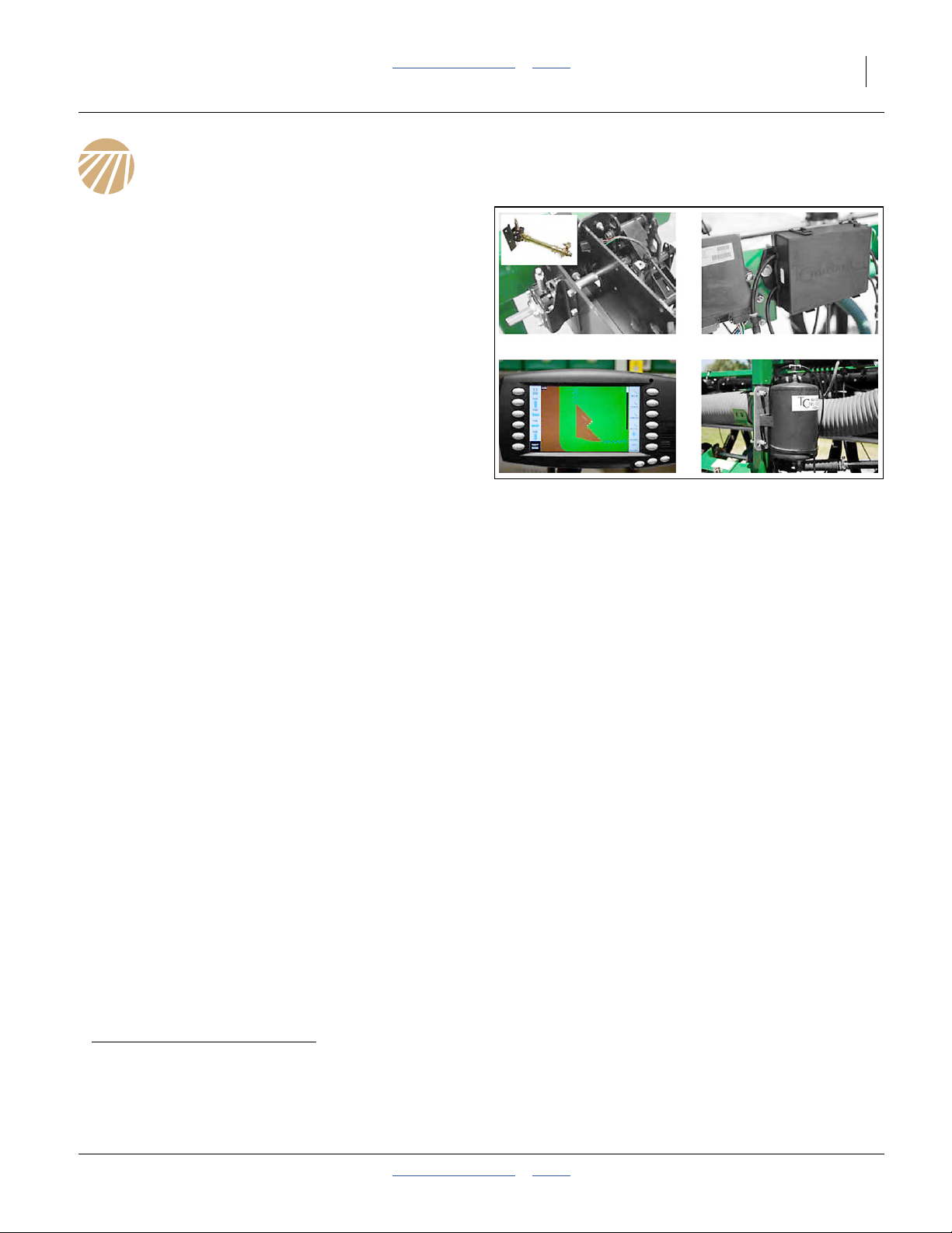
Figure 1
Swath Command™ Components
31548
Components
A field installation kit includes these new components:
• air-operated row unit clutches
• solenoid valves
• compressor, tank and air delivery tubing
• CANbus valve control module
• DICKEY-john® A5 section control console
(supplementing the existing A1or AI110)
These existing planter components are removed:
• electric section clutches (two or three)
• final meter drive input sprockets at rows
There will be fasteners left over.
Additional Components Always Required
Whether factory or field-installed, these optional
components are dealer- or user-installed, and must be
configured prior to use:
• geolocation receiver, such a Trimble® AgGPS®262
(available from Great Plains).
• coordinate augmentation data source, such as a
Trimble® AgGPS®900 RTK rover radio
(available from Great Plains)
Additional Components That May Be Required
Field installation:
• For a pull-type planter with a hydraulic tongue,
manufactured prior to 2012, order one or two sets of
404-228D component mounting brackets and
fasteners (see step 97 on page 15).
Note: See “Options” in Operator manual 403-857M for
component and accessory ordering information.
a. Controlling a larger number of sections requires field installation of additional solenoid valves and CANbus modules. It also requires
sub-inch precision geolocation augmentation data.
b. The system requires a source of sub-meter geolocation data, usually via differential satellite positioning system, such as DGPS.
The antenna, receiver and cable for this are not included in the system. Further, enhanced resolution geolocation data may require
additional receiver capability and may require subscription from an augmentation service provider.
2012-08-23 Table of Contents Index 402-382M
Page 8

4 Swath Command™ Table of Contents Index Great Plains Manufacturing, Inc.
Models and Kits Covered
This manual provides information for Swath Command™
system on the following specific models of Yield-Pro
®
planters. Kit part numbers are for field-install kits.
Planter Model Kit
3PYP-1236 402-393A
3PYP-1238 402-393A
3PYP-1240 402-393A
3PYP-1630 402-394A
3PYP-2320 402-384A
3PYP-24TR36 402-390A
3PYP-24TR38 402-391A
3PYP-24TR40 402-392A
3PYP-3115 402-383A
3PYP-32TR30 402-389A
3PYPA-1236 402-393A
3PYPA-1238 402-393A
3PYPA-1240 402-393A
3PYPA-1630 402-394A
3PYPA-24TR36 402-390A
3PYPA-24TR38 402-391A
3PYPA-24TR40 402-392A
3PYPA-3115 402-383A
3PYPA-32TR30 402-389A
YP1225-1230 402-395A
YP1225-16TR36 402-398A
YP1225-1820 402-399A
YP1225-2315 402-397A
YP1225-24TR 402-396A
YP1225A-1230 402-395A
YP1225A-16TR36 402-398A
YP1225A-1820 402-399A
YP1225A-2315 402-397A
YP1225A-24TR 402-396A
YP1625-1236 402-393A
YP1625-1630 402-380A
YP1625-1670 402-380A
YP1625-2420 402-384A
YP1625-24TR36 402-379A
YP1625-3115 402-383A
Planter Model Kit
YP1625-32TR 402-381A
YP1625A-1236 402-393A
YP1625A-1630 402-380A
YP1625A-1670 402-380A
YP1625A-2420 402-384A
YP1625A-24TR36 402-379A
YP1625A-3115 402-383A
YP1625A-32TR 402-381A
YP2425-2430 402-387A
YP2425-2470 402-387A
YP2425-3620 402-388A
YP2425-4715 402-386A
YP2425-48TR 402-385A
YP2425A-2430 402-387A
YP2425A-2470 402-387A
YP2425A-3620 402-388A
YP2425A-4715 402-386A
YP2425A-48TR 402-385A
YP2425F-2470 402-387A
YP3025-1230 402-403A
YP3025-1270 402-403A
YP3025-16TR36 402-405A
YP3025-1820 402-404A
YP3025-2315 402-401A
YP3025-2335 N/A
YP3025-2415 402-402A
YP3025-24TR 402-400A
YP3025-24TR70 402-400A
YP3025-24TR75 402-400A
YP3025-3610 N/A
YP3025A-1230 402-403A
YP3025A-1270 402-403A
YP3025A-16TR36 402-405A
YP3025A-1820 402-404A
YP3025A-2315 402-401A
Planter Model Kit
YP3025A-2335 N/A
YP3025A-2415 402-402A
YP3025A-24TR 402-400A
YP3025A-24TR70 402-400A
YP3025A-24TR75 402-400A
YP3025A-3610 N/A
YP4025-1630 402-377A
YP4025-1670 402-377A
YP4025-2420 402-384A
YP4025-24TR36 402-406A
YP4025-3115 402-375A
YP4025-3135 N/A
YP4025-3215 402-378A
YP4025-32TR 402-376A
YP4025-32TR70 402-376A
YP4025-4810 N/A
YP4025A-1630 402-377A
YP4025A-1670 402-377A
YP4025A-2420 402-384A
YP4025A-24TR36 402-406A
YP4025A-3115 402-375A
YP4025-3135 N/A
YP4025A-3215 402-378A
YP4025A-32TR 402-376A
a
YP4025A-32TR70 402-376A
YP4025A-4810 N/A
YP4025AF-1670 402-377A
YP4025F-1630 402-377A
YP4025F-1670 402-377A
a
YP4425A-2422 402-384A
a. Not Available.
Swath Command™ is not
presently available for row
spacings at or below
13.8 inches (35 cm)
a
a
a
a
a
a
402-382M Table of Contents Index 2012-08-23
Page 9

Great Plains Manufacturing, Inc. Table of Contents Index General Information 5
Related Documents
Have your planter Operator and Parts manual available
during installation. Also have the following manuals
available:
403-857M
11001-1508
11001-1501
11001-1561A
56110-00
55565-00
-
Great Plains Planter Operator and Parts manuals are
available as PDF files on the Great Plains web site:
Manuals > Planters
The DICKEY-john®manuals above are available as PDF
files on the Great Plains web site:
Manuals > Planters > Service Information & Monitor Manuals
Swath Command operation manual
DICKEY-john® Planter/Drill Control User
Level 1 Operator’s Manual
DICKEY-john® Planter/Drill Control User
Level 2&3 Operator’s Manual
DICKEY-john® Auto Section Control
System Operator’s Manual
(or equivalent manual for a different brand
of swath controller)
Trimble® AgGPS®262 Satellite Receiver
User Guide
(or equivalent manual for a different
geolocation data receiver)
Trimble® AgGPS® 900 Radio
(or equivalent manual for a different
augmentation receiver)
Viair User’s Manual
for 35030-350C (or equivalent manual for
other compressor)
Notations and Conventions
U
F
L
D
Call-Outs
1 9
to
a z
to
11 28
to Two digit callouts represent the same existing
101 288
This manual fully describes a system based on Great
Plains-provisioned DICKEY-john®IntelliAg® seed
monitor (A1 / AI110), and the DICKEY-john®A5 terminal
and Great Plains Swath Command™ implement
components.
It is possible to use aftermarket or customer-provisioned
seed monitor, swath control terminal, geolocation
receiver and clutch control air system. This manual
provides only limited support for such installations,
primarily reference data concerning clutch placement,
clutch groupings and row geometry.
Single-digit or single-letter callouts identify
components in the currently referenced
Figure. These numbers may be reused for
different items from page to page.
(old) parts throughout this manual.
to Three digit callouts represent the same new
parts throughout this manual.
“Left”/LH and “Right”/RH are facing in
the direction of machine travel. An
R
orientation rose in the line art
illustrations shows the directions of
Left, Right, Front, Back, Up, Down.
B
2012-08-23 Table of Contents Index 402-382M
Page 10
6 Swath Command™ Table of Contents Index Great Plains Manufacturing, Inc.
Prepare Planter
Verify Compatibility
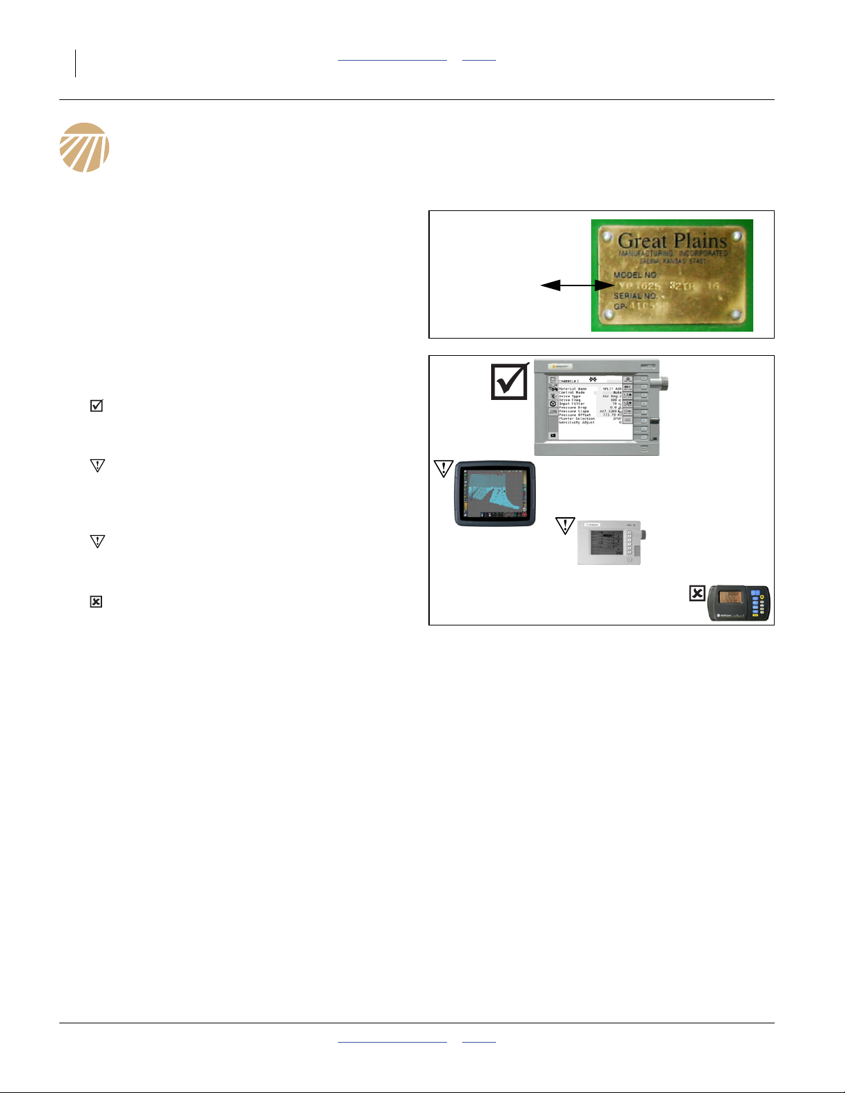
1. Verify that you have the correct kit. Check your
planter model number (from the serial number
plate) against the kit part number table on page 4.
If your planter is not listed (or has an N/A), stop.
Contact your dealer.
If the kit you have is not for your planter, stop.
Contact your dealer.
2. Verify that the planter has a compatible seed
monitor.
Verify that the monitor console for your planter is
a DICKEY-john®IntelliAg® 10 inch color display,
Model A1, A1+ or AI100.
If you have a DICKEY-john®IntelliAg® 12 inch
color display, Model AI120, and Swath Command™
was not factory-installed, have your dealer contact
the factory.
If you have a 5 inch monochrome IntelliAg
console, a separate console upgrade is required.
Contact your dealer.
If you have a Seed Manager™ SE console, the
Swath Command™ Section Control kit is
completely incompatible. Contact your dealer for kit
return.
3. Plan the air clutch installation. Meter shafts run the
entire length of each section (center or wing).
Removal requires a clear path from at least one end
of the shaft, into the workspace, for that length.
Horizontal-Fold 2-Section Horizontal-Fold 3-Section Stack-Fold
In general, access to the drive shafts
is easiest from the wing ends. The
wings must be positioned such that
the wing-end casters swing clear of
the shaft path.
The wings must be partially or fully
folded for access to the center
section drive shaft.
In general, access to the drive shafts
is easiest from the wing ends. The
wings must be positioned such that
the wing-end casters swing clear of
the shaft path.
YP24 and YP44: Wing drive shafts
are in two segments with a coupler.
®
Kit: 402-381A
Updating the center section shaft
must be done with the planter fully
folded.
Updating the wing shafts must be
done with the planter fully unfolded.
402-382M Table of Contents Index 2012-08-23
Page 11

Great Plains Manufacturing, Inc. Table of Contents Index Prepare Planter 7
Tools Required
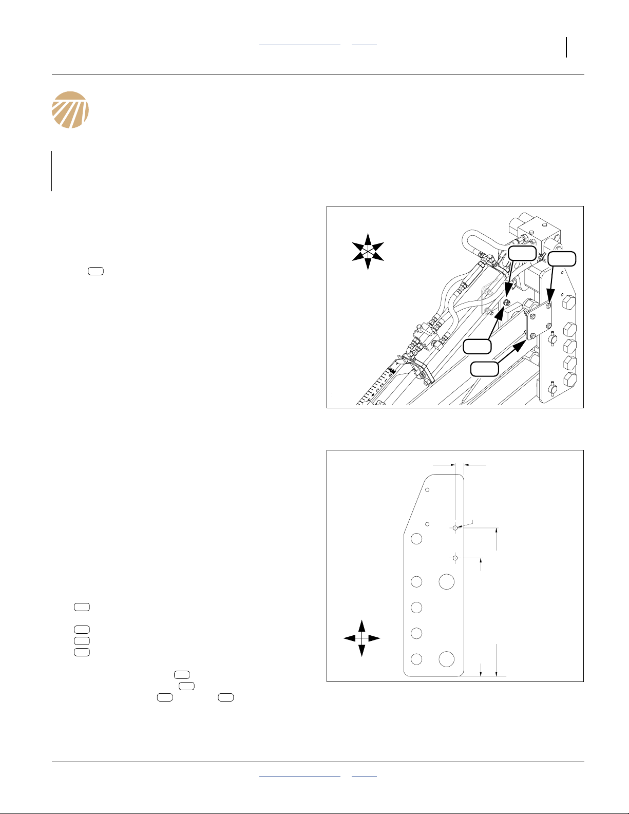
Shaft Locator Tool
Refer to Figure 2
Kit installation requires removal and re-installation of
meter line shafts and their bearings. Bearing flanges
must be aligned during re-installation. Great Plains
offersa a tool kit to simplify this task, shown at right.
4. Check that alignment bolts are set correctly.
With the leading edge of the tool against a flat
surface, the bolt sets the face of the tool
perpendicular to that surface. Adjust jam nuts
as needed.
232
1
2
1
238
232
238
Other Tools Required
• The tractor to be used afield with the upgraded planter
must be present for spotting, unfolding, folding and
final setup.
• The work area must have sufficient area for a partially
unfolded planter (fully unfolded 3PYP/A), including
clearance at each wing end for complete removal of
wing-long meter drive shafts.
• Folding planter only: A fish wire or stiff fish tape may
be needed to pull the air tubing through the left wing
pull bar. If the fish line cannot easily be inserted
through the pull bar, it will be necessary to remove the
existing hoses and harnesses, and re-pull them with
the air tubing.
• 3PYP/A planter only: The work area must have
sufficient vertical clearance for a fully folded planter.
• The work area must be well illuminated, with a clear
surface beneath for recovery of any dropped parts.
• One or more adjustable stand are recommended for
supporting extended free shaft ends.
• The Operator and Parts manuals for the planter must
be present. Check the Great Plains web to ensure
they are current.
• Twin-Row only: The Seed Rate manual is needed if
sprocket index settings need to be restored after the
installation. For Air-Pro® models, have the 812-391C
timing tool on hand for restoring index settings.
• Pre-2012 Hydraulic Tongue only: a drill with a
17
⁄32inch (13.5 mm) bit and suitable pilot bit.
•A1⁄4inch (6.3 mm) flat-face punch is needed for
driving roll pins.
2
Figure 2
402-270A Locator Tool Kit
Machine Damage and Population Risks:
Use the locator tools or precision optical alignment. If a shaft
has sag, excess bearing wear results. In more severe cases of
bearing mis-alignment, a hard-to-turn shaft could cause
excess chain wear, or drive system slippage and low
populations on a ground-drive planter, and motor overheating
on a hydraulic-drive planter.
• A cleaning rag and fine point indelible marker are
recommended for identifying the location and
orientation of removed shafts.
• A note pad is recommended for recording locations of
some re-used and/or replaced components. A digital
camera may also be helpful.
• Only basic hand tools, including hex keys in fractional
sizes, are otherwise required.
• Cable ties.
Prepare Planter
5. Move the planter to the work space.
6. Unfold the wings.
7. Lower the row units.
8. Shut down the tractor.
9. Unplug all electrical connections at planter hitch.
34066
a. Great Plains dealers often have a locator kit on hand.
2012-08-23 Table of Contents Index 402-382M
Page 12
8 Swath Command™ Table of Contents Index Great Plains Manufacturing, Inc.
Replace Electric Clutches
Depending on planter model and drive type, there are
two or three electric clutch assemblies that are replaced
with a simple sprocket. Due to their electrical load, these
cannot be left connected to the system harness, and
without electrical control, would leave the drive system
disabled.
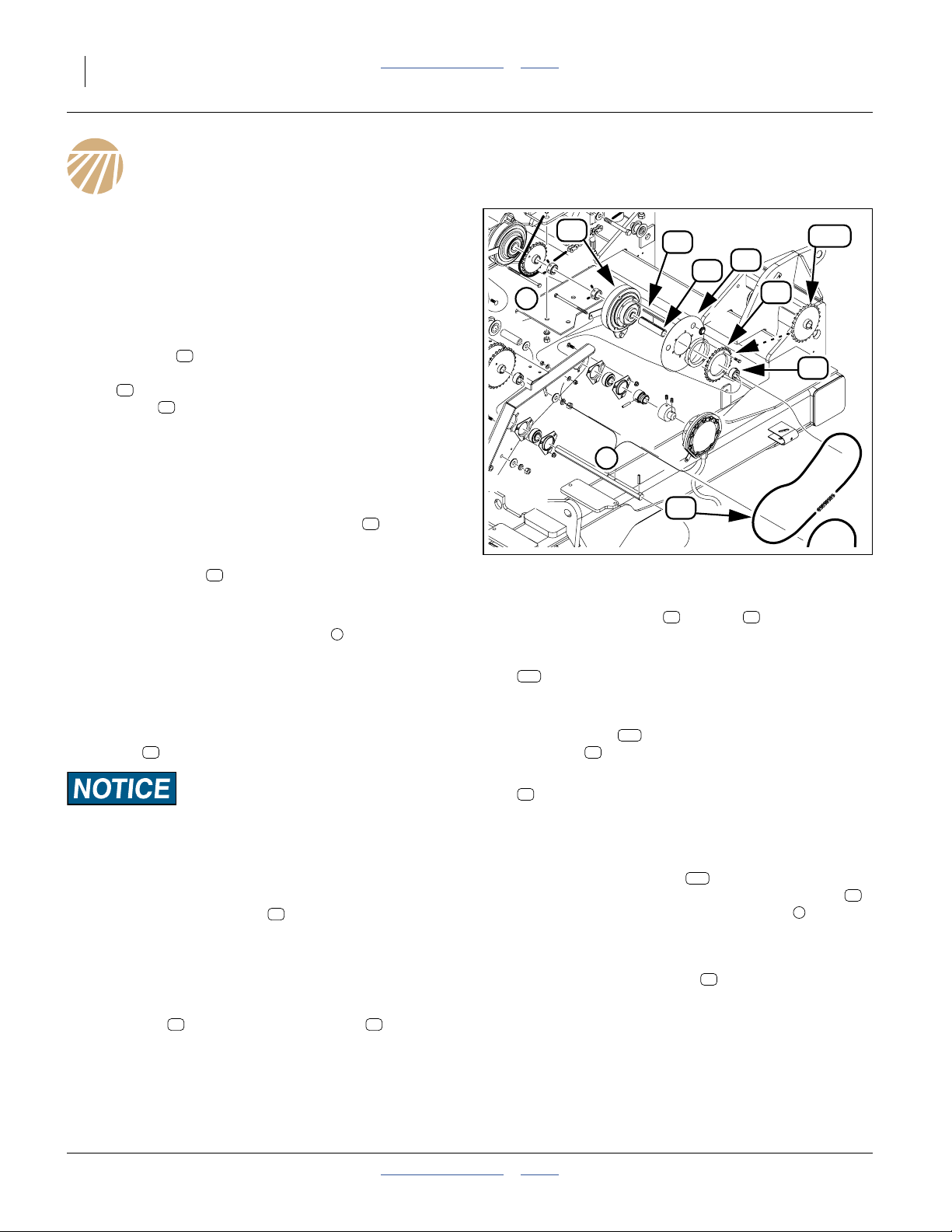
Refer to Figure 3
(which depicts a clutch on a hydraulic drive 3PYP planter)
These clutches are generally present at shaft ends,
27
and may be secured on their shaft by set screw lock
collars , roll pins, or both. Older assemblies may lack
the oil shield depicted at right.
15
16
10. Locate all the electric clutches on the planter.
11. Unplug the lead at each clutch.
Update one clutch at a time.
12. Measure from any convenient reference point to the
center-line of a clutch output sprocket (along the
24
shaft). Make a record of this location. The
replacement sprocket provided needs to align with
the drive chain , and must be at this same
12
position on the shaft (installed at step 18).
13. At the end of the shaft where you plan to remove a
clutch, examine any components mounted
1
between the clutch and shaft end (and there may be
none).
Note: Check your Parts manual to ensure that you know
how these go back together.
14. Loosen or release spring on idlers (not shown) on
12
chain .
Roll Pin Damage Risk:
If any roll pins need to be removed, drive them out carefully
and save them. The kits do not include replacement roll pins.
15. Remove and save all components (except bearings,
if possible), between shaft end, up to and including
the outside clutch collar or roll pin (not shown).
15
Loosen bearings and/or brackets as needed to free
shaft end. If may be necessary to free the other end
of the shaft and slide it clear of the clutch. Take note
of, and save, any removed components.
16. Lift chain off clutch output sprocket . Remove
12 24
the clutch assembly. It is not necessary to remove
the sprocket, spacer and oil shield from the clutch.
None of these parts are reused.
17. Remove the bushing and key . These are not
18. Select one new:
19. Slide sprocket loosely onto the drive shaft. Loop
20. Add one saved:
21. As needed, reposition the shaft, bearings and
22. Adjust the new sprocket to the position
23. Reinstall any end-of-shaft components removed at
24. Engage idlers to set chain to recommended
25. Repeat step 12 through step 24 for each clutch.
27
2
28
13
16
24
256
15
1
12
Figure 3
Typical Electric Clutch
13 28
reused.
256
808-309C SPKT 50C25 X 7/8 HEX BORE
This is a plain 25 tooth sprocket with a7⁄8inch
hexagonal bore. It is stamped “25” on each side.
256
the chain over the sprocket.
15
402-025S LOCK COLLAR, 7/8 HEX W/ SET SC
12
Slide it loosely onto the shaft.
brackets to its original placement.
256
recorded at step 12. Secure in place with collar
(or original roll pin) and the inside collar .
step 15.
12
slack. (See “Chain Maintenance” in the 403-857M
Operator manual).
25060
15
2
402-382M Table of Contents Index 2012-08-23
Page 13
Great Plains Manufacturing, Inc. Table of Contents Index 9
Install Air Clutches
Install Center Air Clutches
If the planter frame does not have a center section, for
example Models YP1225 and YP1625, continue at
“Install Wing Air Clutches” on page 12.
26. Connect the hitch hydraulics and harnesses at the
tractor.
27. a. For Model 3PYP and 3PYPA,
completely fold the wings.
b. For all other Models,
partially or completely fold the wings.
This provides access to center section shaft ends.
28. Lower the openers.
29. Shut down the tractor. Disconnect hydraulics and
harnesses at hitch.
14
26
11
17
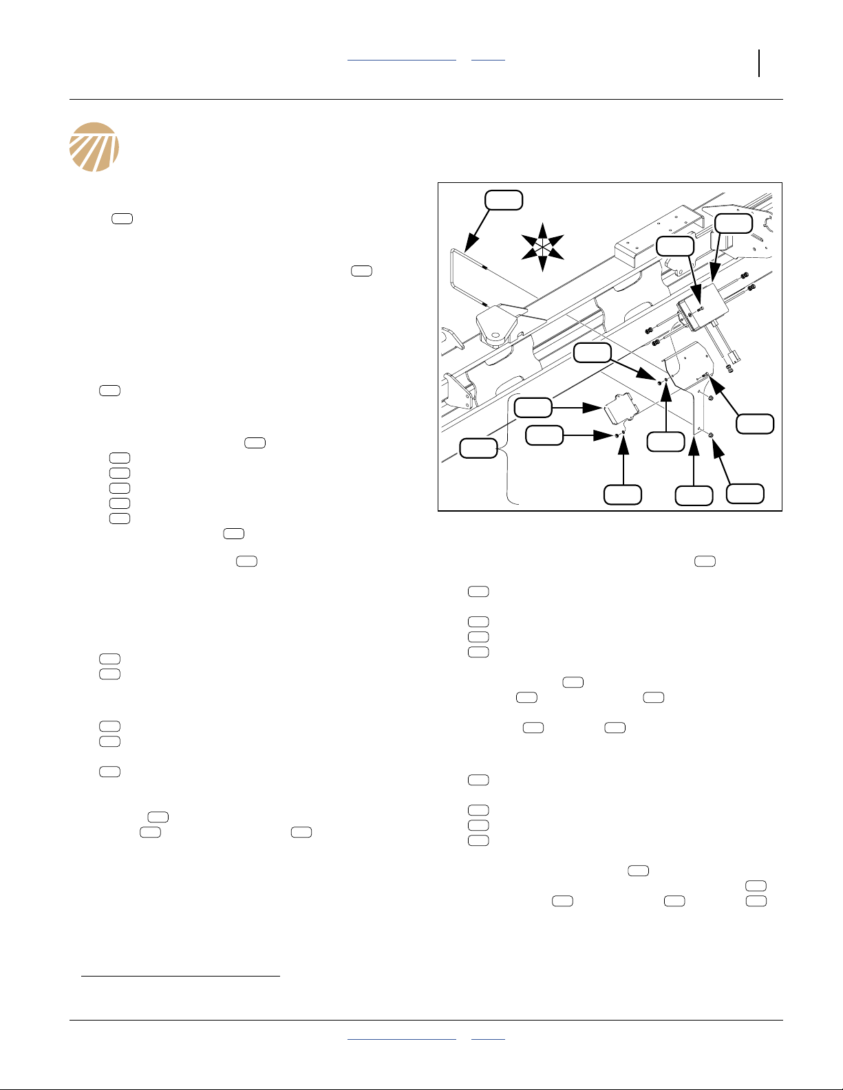
Assess The Center Shaft
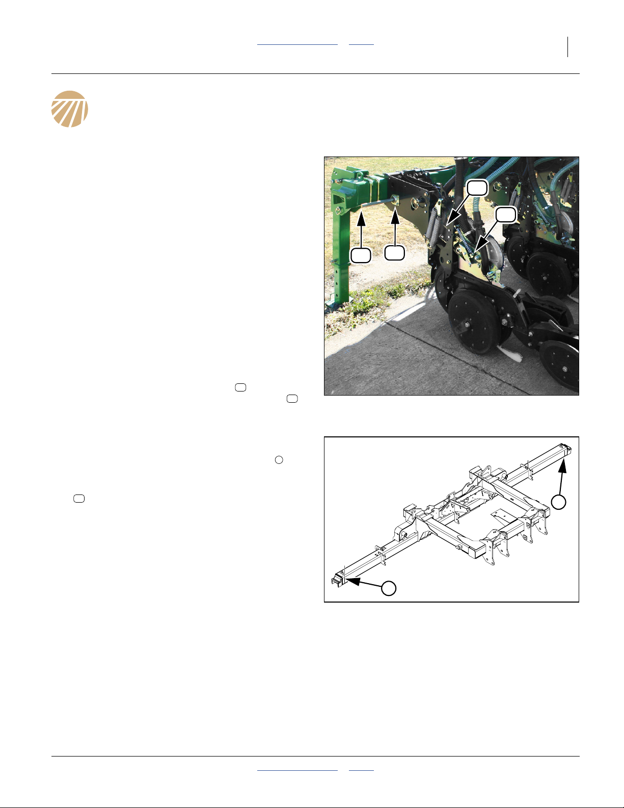
Refer to Figure 4
(which depicts a 3PYPA center section shaft)
30. At one end of the center section, measure the
length of exposed meter drive shaft , from tip of
shaft to row unit mount sidewall (not to bearing
face - the bearing may be relocated during this
installation). Record the dimension.
Refer to Figure 5
(which depicts a 3PYP/A center section)
31. Mark the approximate end-of-shaft locations on
the tool bar (needed for step 42).
32. Locate the 30T shaft input sprocket (not shown):
23
808-319C SPKT 50C30 X 7/8 HEX BORE
Measure the position of this sprocket with reference
to the row unit shanks on either side. Record these
dimensions, and whether the sprocket is secured in
place by no collars, one LH, one RH or two collars.
33. Along the entire length of the shaft, locate each pin
hole and roll pin (not shown, and there may be
none). Clean the shaft near each hole. Mark
occupied holes (for example “I”) and empty holes
(for example “o”).
34. Twin Row Only (Air-Pro® and finger meter only):
Check for deliberate stagger (consistent difference
sprocket tooth orientation at the meter sprocket).
For the front row, note the tooth number at top dead
center. Record that number and the T.D.C. tooth
number for the rear row.
Note: Lock collar (not shown) locations, other than for
shaft input sprocket, do not need to be recorded.
The clutch layout drawings show the final locations
of all collars.
14
26
1
Figure 4
Center Section Meter Shaft
1
Figure 5
Center Shaft End Points
34056
1
34067
2012-08-23 Table of Contents Index 402-382M
Page 14
10 Swath Command™ Table of Contents Index Great Plains Manufacturing, Inc.
Remove Center Shaft
Refer to Figure 6
(which depicts a 3PYPA center section shaft)
35. Relax the idlers on the chain driving the shaft input
sprocket.
36. At each center section row, relax the row unit
17 12
idlers to slacken the final drive chain .
37. Along the line shaft :
14
- loosen all lock collar set screws (not shown)
- loosen all sprocket set screws (not shown)
- carefully drive out and save roll pins (not shown)
38. Make arrangements to support the free shaft
14
end . From one end, for example the RH end,
begin driving the shaft toward the other end.
39. Use a rag to clean the free end of the shaft . Mark
14
it (for example) “CTR LH END”. Shafts are often
section-specific and not symmetrical end-to-end.
40. Continue driving the shaft out. As the shaft exits
14
each collar and sprocket, recover and save these
parts. Some are re-used.
Remove Bearings (Conditional)
41. Check the materials list on the opener layout
drawing for your kit, found in “Swath Command™
Planter Clutch Layouts”, pages 48 through 97.
If the kit contains, for the center section, any:
106
402-273K TRU-COUNT SINGLE ROW ASM or
144
402-329K TRU-COUNT SHORT ROW SINGLE ASM
do not remove the bearings at rows indicated by the
drawing reference number for either of those clutch
kits.
Otherwise, remove and save the bearing assembly
26
and its fasteners, at every row.
Attach Locator Tools
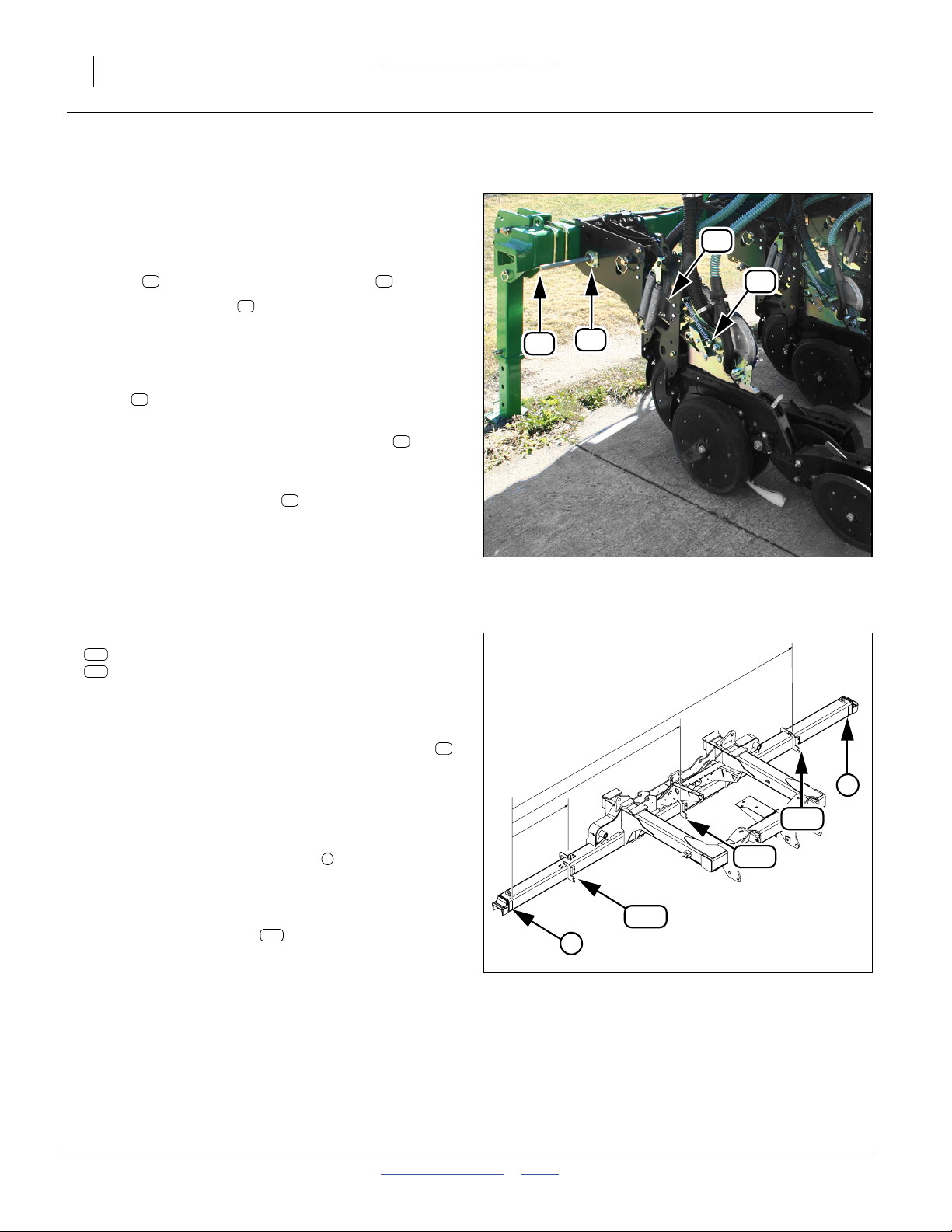
Refer to Figure 7
(which depicts a 3PYP/A center section)
42. In between the shaft-end marks made at step 31,
make additional marks at the positions:
1
⁄6(17%),1⁄2(50%) and5⁄6(83%)
in between the end marks.
43. Attach one locator tool as close as practical to
104
each marked location. Each locator equally
supports1⁄3 of the shaft length at these positions.
Make sure tool is perpendicular to tool bar, and
snug front-to-back.
1
14
17%
26
Figure 6
Center Section Line Shaft
50%
104
1
Figure 7
Attach Center Shaft Locators
12
17
34056
83.%
1
104
104
34067
402-382M Table of Contents Index 2012-08-23
Page 15

Great Plains Manufacturing, Inc. Table of Contents Index Install Air Clutches 11
Install Center Air Clutches
44. Consult the layout drawing for your kit (found in
pages 48 through page 97).
45. Note which types of clutch assemblies are supplied
in your kit (there are six different total assemblies,
and as many as four combinations per kit). Find the
detailed assembly drawing and instructions for each
in the Appendix, found on pages listed at right.
46. Working from left to right, install the specified
components ahead of, at and in between each row.
see the checklist at right for items to watch out for
during row installation.
Align Center Shaft
When the right-most row clutch has been installed, and
any final lock collar or roll pin installed, make final shaft
adjustments.
47. Check that all bearing flangettes are slightly loose.
Working from left to right:
48. Push the line shaft fully into the hex cut in a locator
tool.
49. Tighten flangette nuts on bearings immediately left
and right of the locator tool.
50. Repeat step 48 and step 49 for the remaining tools.
At the left end of the center section:
51. Being careful to not disturb the shaft position,
tighten the flangette nuts of the left end row.
At the right end of the center section:
52. Being careful to not disturb the shaft position,
tighten the flangette nuts of the right end row.
Working from left to right:
53. Being careful to not disturb the shaft position,
tighten the flangette nuts at each row.
At the left end of the shaft:
54. Adjust the left-right position of the shaft to match the
measurement taken at step 30.
Working from left to right:
55. Slide each lock collar into gentle contact with the
associated bearing shown in the layout drawing.
Secure the set screws.
56. Adjust the line shaft input sprocket so that the chain
is vertical. Secure the sprocket set screws.
57. Re-engage meter drive chain idlers. See special
instructions at right for twin-row chains.
58. Remove the locator tools. This completes the center
section clutch installation.
Clutch Assembly Installation Details
402-273K-ASY: page 37 402-279K-ASY: page 43
402-275K-ASY: page 39 402-281K-ASY: page 45
402-276K-ASY: page 41 402-329K-ASY: page 47
Row Item Checklist
• Route shaft through locator tools as encountered.
• Add lock collar left of clutch where specified.
• Install roll pins as marked on shaft.
• Loop meter chain(s) when installing clutch.
• Add lock collar right of clutch where specified.
• Add shaft input sprocket when chain encountered.
Be sure to re-install any lock collars as recorded at
step 32.
• Do not tighten any collar or sprocket set screws
during row installation.
• Do not remove any chain slack during row
installation.
Twin Row Chain Alignment
If the planter is only ever used:
• with Singulator Plus™ (green wheel) meters, or
• at seed spacings below 61⁄2inches (16.5 cm), or
• with Air-Pro® seed discs having more than 24
pockets,
then skip this alignment.
If no deliberate sprocket indexing was noted at step 34,
re-engage meter chains with both meter sprockets in
the same tooth orientation (for example, with both
sprockets having tooth 1 at top dead center).
Otherwise, engage the chain for the front meter as
noted at step 34, and engage or adjust the chain for the
rear meter as noted.
Engage both idlers. Recheck the tooth number
relationship.
2012-08-23 Table of Contents Index 402-382M
Page 16
12 Swath Command™ Table of Contents Index Great Plains Manufacturing, Inc.
Install Wing Air Clutches
59. Connect the hitch hydraulics and harnesses at the
tractor.
60. a. For Model 3PYP and 3PYPA,
completely unfold the wings.
b. For all other Models,
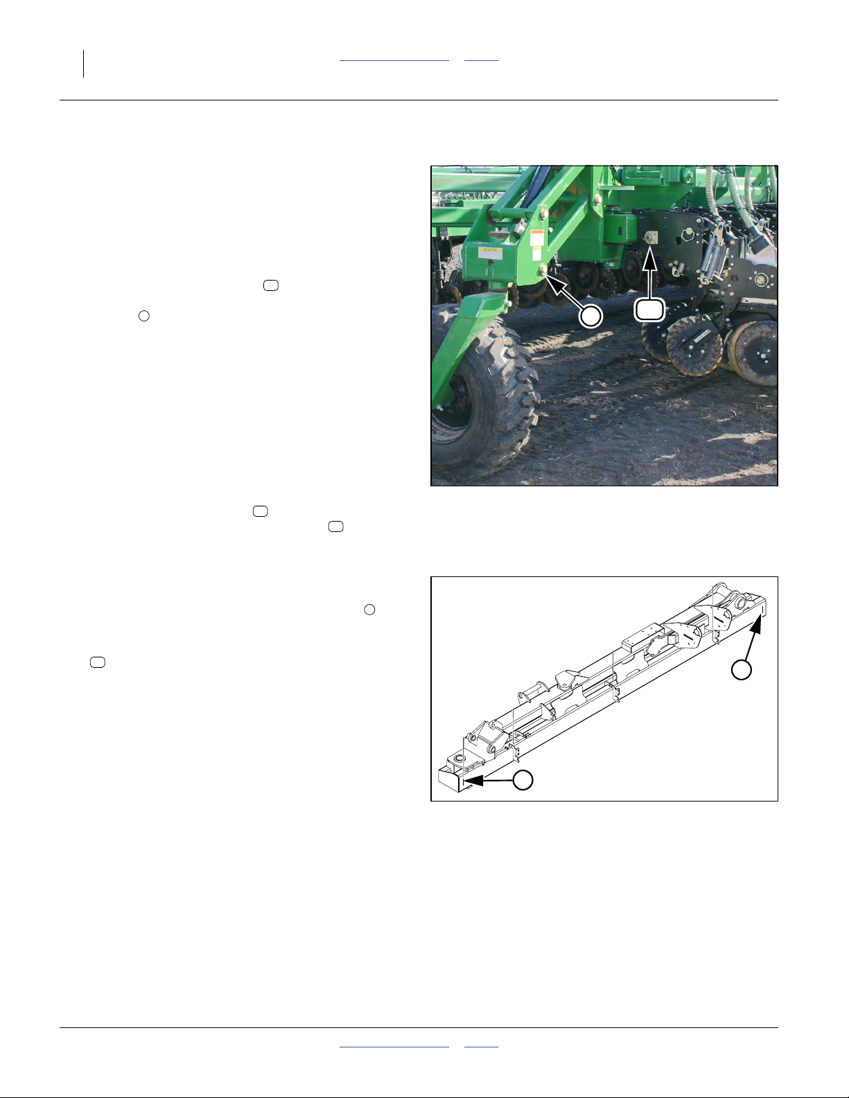
Refer to Figure 8: take note of the location of the
14
14
26
1
Figure 8
14
34069
Wing End Line Shaft
1
1
1
Figure 9
Wing Shaft End Points
Note: Lock collar (not shown) locations, other than for
line shaft input sprocket, do not need to be
recorded. The clutch layout drawings show the
final locations of all collars.
34070
outside end of the line shaft . Partially or
completely fold the wings, leaving the wing-end
casters oriented so that they do not obstruct shaft
1
removal.
61. Lower the openers.
62. Shut down the tractor. Disconnect hydraulics and
harnesses at hitch.
Start with the left wing.
Assess The Wing Shaft
Refer to Figure 8
(which depicts a YP24 left wing shaft)
63. At one end of the wing, measure the length of
exposed meter drive shaft , from tip of shaft to
row unit mount sidewall (not to bearing face - the
bearing may be relocated during this installation).
Record the dimension.
Refer to Figure 9
(which depicts a YP40 left wing)
64. Mark the approximate end-of-shaft locations on
the tool bar (needed for step 76).
65. Locate the 30T shaft input sprocket (not shown):
23
808-319C SPKT 50C30 X 7/8 HEX BORE
Measure the position of this sprocket with reference
to the row unit shanks on either side. Record these
dimensions, and whether the sprocket is secured in
place by no collars, one LH, one RH or two collars.
66. Locate any coupler on the shaft. Decide on a
removal/re-insertion strategy (both sections from
one end, or each section from each end).
67. Along the entire length of the shaft, locate each pin
hole and roll pin (not shown, and there may be
none, and there may be one coupler with two pins).
Clean the shaft near each hole. Mark occupied
holes (for example “I”) and empty holes (for example
“o”).
68. Twin Row Only (Air-Pro® and finger meter only):
Check for deliberate stagger (consistent difference
sprocket tooth orientation at the meter sprocket).
For the front row, note the tooth number at top dead
center. Record that number and the T.D.C. tooth
number for the rear row.
402-382M Table of Contents Index 2012-08-23
Page 17
Great Plains Manufacturing, Inc. Table of Contents Index Install Air Clutches 13
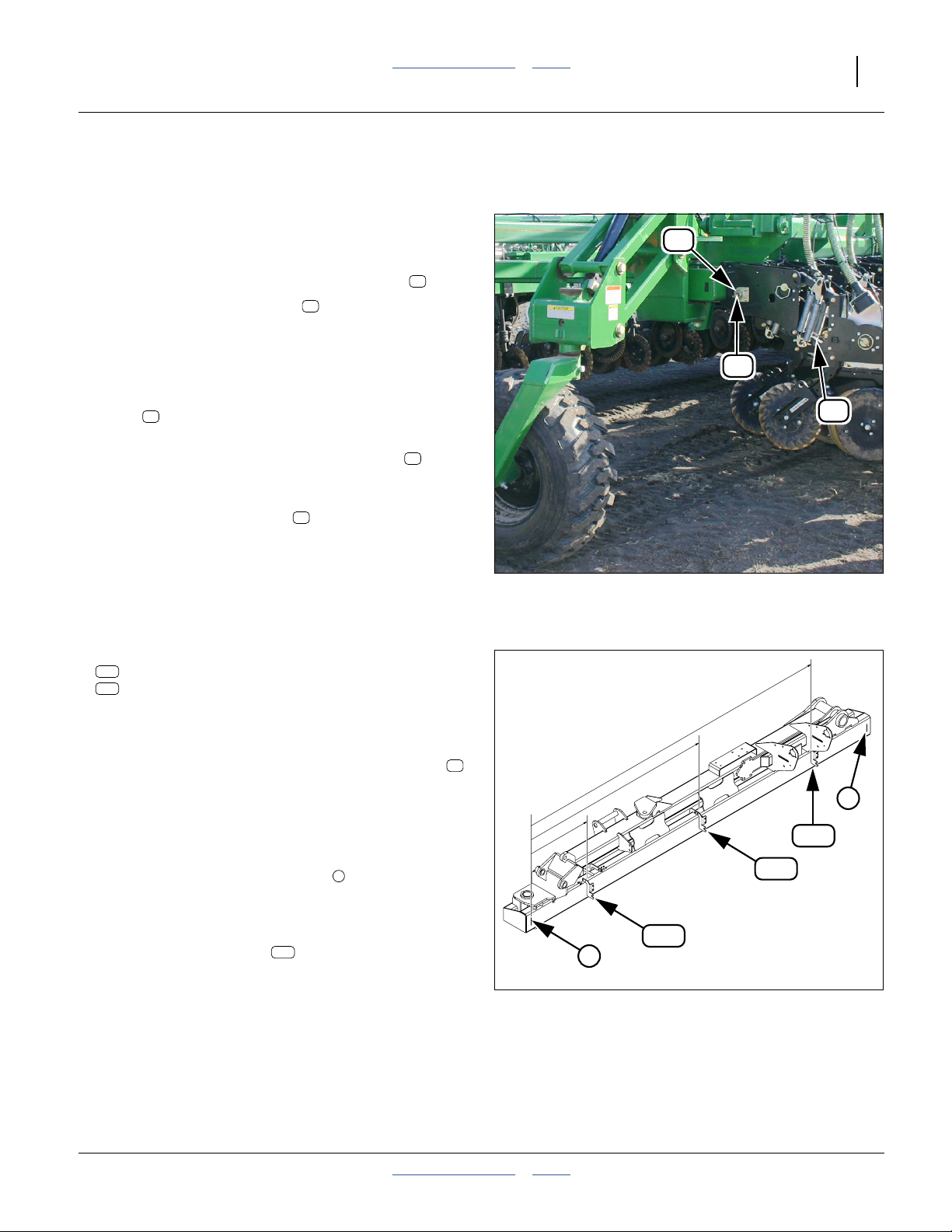
Remove Wing Shaft
Refer to Figure 10
(which depicts a YP24 wing shaft)
69. Relax the idlers on the chain driving the shaft input
sprocket.
26
70. At each center section row, relax the row unit idlers
(not shown) to slacken the final drive chain .
71. Along the meter drive shaft :
14
12
- loosen all lock collar set screws (not shown)
- loosen all sprocket set screws (not shown)
- carefully drive out and save roll pins (not shown)
- remove and save any coupler
14
72. Make arrangements to support the free shaft
14
end . From one end, for example the RH end,
12
begin driving the shaft toward the other end.
73. Use a rag to clean the free end of the shaft . Mark
14
it (for example) “LW LH END”. Shafts are often
section-specific and not symmetrical end-to-end.
74. Continue driving the shaft out. As the shaft exits
14
each collar and sprocket, recover and save these
parts. Some are re-used.
Remove Bearings (Conditional)
75. Check the materials list on the opener layout
drawing for your kit, found in “Swath Command™
Figure 10
Wing Line Shaft
34069
Planter Clutch Layouts”, pages 48 through 97.
If the kit contains, for the center section, any:
106
402-273K TRU-COUNT SINGLE ROW ASM or
144
402-329K TRU-COUNT SHORT ROW SINGLE ASM
do not remove the bearings at rows indicated by the
83.%
drawing reference number for either of those clutch
kits.
Otherwise, remove and save the bearing assembly
and its fasteners, at every row.
26
50%
1
Attach Locator Tools
Refer to Figure 11
(which depicts a YP40 wing)
76. In between the shaft-end marks made at step 31,
make additional marks at the positions:
1
⁄6(17%),1⁄2(50%) and5⁄6(83%)
1
in between the end marks.
77. Attach one locator tool as close as practical to
104
each marked location. Each locator equally
supports1⁄3 of the shaft length at these positions.
Make sure tool is perpendicular to tool bar, and
snug front-to-back.
17%
104
1
Figure 11
Attach Wing Shaft Locators
104
104
34070
2012-08-23 Table of Contents Index 402-382M
Page 18

14 Swath Command™ Table of Contents Index Great Plains Manufacturing, Inc.
Install Wing Air Clutches
78. Consult the layout drawing for your kit (found in
pages 48 through page 97).
79. Note which types of clutch assemblies are supplied
in your kit (there are six different total assemblies,
and as many as four combinations per kit). Find the
detailed assembly drawing and instructions for each
in the Appendix, found on pages listed at right.
80. Working from left to right, install the specified
components ahead of, at and in between each row.
see the checklist at right for items to watch out for
during row installation.
81. When all rows are updated, re-install any coupler.
Align Wing Shaft
When the right-most row clutch is installed, and any final
collar or roll pin installed, make final shaft adjustments.
82. Check that all bearing flangettes are slightly loose.
Working from left to right:
83. Push the shaft fully into the hex cut of a locator tool.
84. Tighten flangette nuts on bearings immediately left
and right of the locator tool.
85. Repeat step 83 and step 84 for the remaining tools.
At the left end of the center section:
86. Being careful to not disturb the shaft position,
tighten the flangette nuts of the left end row.
At the right end of the center section:
87. Being careful to not disturb the shaft position,
tighten the flangette nuts of the right end row.
Working from left to right:
88. Being careful to not disturb the shaft position,
tighten the flangette nuts at each row.
At the left end of the shaft:
89. Adjust the left-right position of the shaft to match the
measurement taken at step 63.
Working from left to right:
90. Slide each lock collar into gentle contact with the
associated bearing shown in the layout drawing.
Secure the set screws.
91. Adjust the line shaft input sprocket so that the chain
is vertical. Secure the sprocket set screws.
92. Re-engage meter drive chain idlers. See special
instructions at right for twin-row chains.
93. Remove the locator tools. This completes a wing
clutch installation.
94. Repeat step 63 through step 93 for the right wing.
Clutch Assembly Installation Details
402-273K-ASY: page 37 402-279K-ASY: page 43
402-275K-ASY: page 39 402-281K-ASY: page 45
402-276K-ASY: page 41 402-329K-ASY: page 47
Row Item Checklist
• Route shaft through locator tools as encountered.
• Add lock collar left of clutch where specified.
• Install roll pins as marked on shaft.
• Loop meter chain(s) when installing clutch.
• Add lock collar right of clutch where specified.
• Add shaft input sprocket when chain encountered.
Be sure to re-install any lock collars as recorded at
step 32.
• Do not tighten any collar or sprocket set screws
during row installation.
• Do not remove any chain slack during row
installation.
Twin Row Chain Alignment
If the planter is only ever used:
• with Singulator Plus™ (green wheel) meters, or
• at seed spacings below 61⁄2inches (16.5 cm), or
• with Air-Pro® seed discs having more than 24
pockets,
skip this alignment.
If no deliberate sprocket indexing was noted at step 34,
re-engage meter chains with both meter sprockets in
the same tooth orientation (for example, with both
sprockets having tooth 1 at top dead center).
Otherwise, engage the chain for the front meter as
noted at step 34, and engage or adjust the chain for the
rear meter as noted.
Engage both idlers. Recheck the tooth number
relationship.
402-382M Table of Contents Index 2012-08-23
Page 19
Great Plains Manufacturing, Inc. Table of Contents Index 15
Install Compressor
Compressor installation varies by hitch type:
Pull Type, Hydraulic Tongue: below
Pull Type, Three-Point: page 17
3PYP/A Three-Point: page 18
Hydraulic Tongue (H.T.) Compressor Installation
Refer to Figure 12
If the hydraulic tongue already has a compressor mount
bracket available, continue at “Install Compressor
Mount (H.T.)” on page 16.
Note: 2012 and later hydraulic tongues have these
Install H.T. Mount Bracket(s)
Swath Command™ kits do not include mount brackets.
The necessary parts are presumed to have been
separately ordered.
Prepare H.T. Hitch Weldment
Refer to Figure 13 (showing right side of hitch)
Note: By convention the Swath Command™ compressor
95. Mark and center-punch locations as shown near the
96. Use a pilot bit and a17⁄32inch (13.5 mm) bit to
Affix H.T. Bracket(s)
Refer to Figure 12 and Figure 13
97. Select one or two:
209
brackets. Earlier tongues do not, and must be
upgraded with parts purchased separately (see
parts list in step 97).
is installed on the right side of the hitch. The
second mount bracket, on the left side, would be
used for a Row-Pro™ compressor.
leading right edge of the hitch weldment. If two sets
of mount brackets are on hand, mark holes on the
left side as well (also near leading edge).
create two or four holes.
209
404-228D HYD HITCH COMP MOUNT BRACKET
and two or four sets:
227
802-091C HHCS 1/2-13X1 1/2 GR5
246
804-015C WASHER LOCK SPRING 1/2 PLT
239
803-020C NUT HEX 1/2-13 PLT
Position each bracket forward of the hitch
weldment. Insert a bolt from the outside. Secure
with lock washers and nuts .
209
227
246 239
U
R
F
B
L
D
H.T. Compressor Mount Check
1.0 in. (25.4 mm)
U
B
F
D
239
209
Figure 12
in.
32
⁄
17
∅
(13.5 mm)
in. (43.8 cm)
4
⁄
1
in. (34.9 cm)
17
4
⁄
3
13
Figure 13
H.T. Mount Hole Locations
246
227
34072
34073
2012-08-23 Table of Contents Index 402-382M
Page 20
16 Swath Command™ Table of Contents Index Great Plains Manufacturing, Inc.
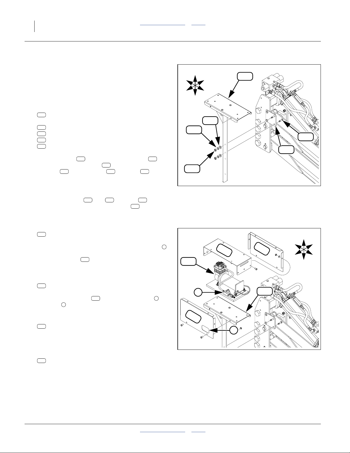
Install Compressor Mount (H.T.)
Note: By convention, the Swath Command™
compressor is installed on the right hand side of the
hitch. If a Row-Pro™ compressor is already
installed there, the Swath Command™
compressor may be installed on the left hand side.
Refer to Figure 14
98. Select one new:
211
404-861H 12V COMP MOUNT WELDMENT
and two sets:
227
802-091C HHCS 1/2-13X1 1/2 GR5
247
804-016C WASHER FLAT 1/2 SAE PLT
246
804-015C WASHER LOCK SPRING 1/2 PLT
239
803-020C NUT HEX 1/2-13 PLT
Insert the bolts from behind the bracket .
Add the mount weldment . Secure with flat
washers , lock washers and nuts .
227 209
211
247 246 239
B
R
U
D
246
239
L
F
247
211
227
209
Install Compressor (H.T.)
B
R
34075
U
L
F
D
Refer to Figure 15
99. If the side covers ( and ) and top are
pre-installed on the mount weldment , and the
compressor is not pre-installed, remove the covers,
saving the fasteners.
100. Select one:
263
823-330C TRU-COUNT COMPRESSOR ASSEMBLY
Orient the compressor assembly so that the valve
is to the outside. Secure it to the platform of the
mount weldment using the fasteners provided.
207 208 206
211
211
Figure 14
H.T. Compressor Mount
1
206
208
263
Install Compressor Covers (H.T.)
101. Select one:
207
404-226D TC COMPRESSOR COVER SIDE R
211
Orient the side cover with the access port at
the valve . Loosely secure cover to mount with
provided fasteners.
102. Select one:
208
1
404-227D TC COMPRESSOR COVER SIDE L
207 2
1
207
2
Loosely secure cover to mount with provided
fasteners.
103. Select one:
206
404-225D 12 COMPRESSOR COVER TOP
Figure 15
H.T. Compressor
34075
Completely secure top to side covers with provided
fasteners.
104. Continue at “Install Valve Blocks” on page 19.
402-382M Table of Contents Index 2012-08-23
Page 21
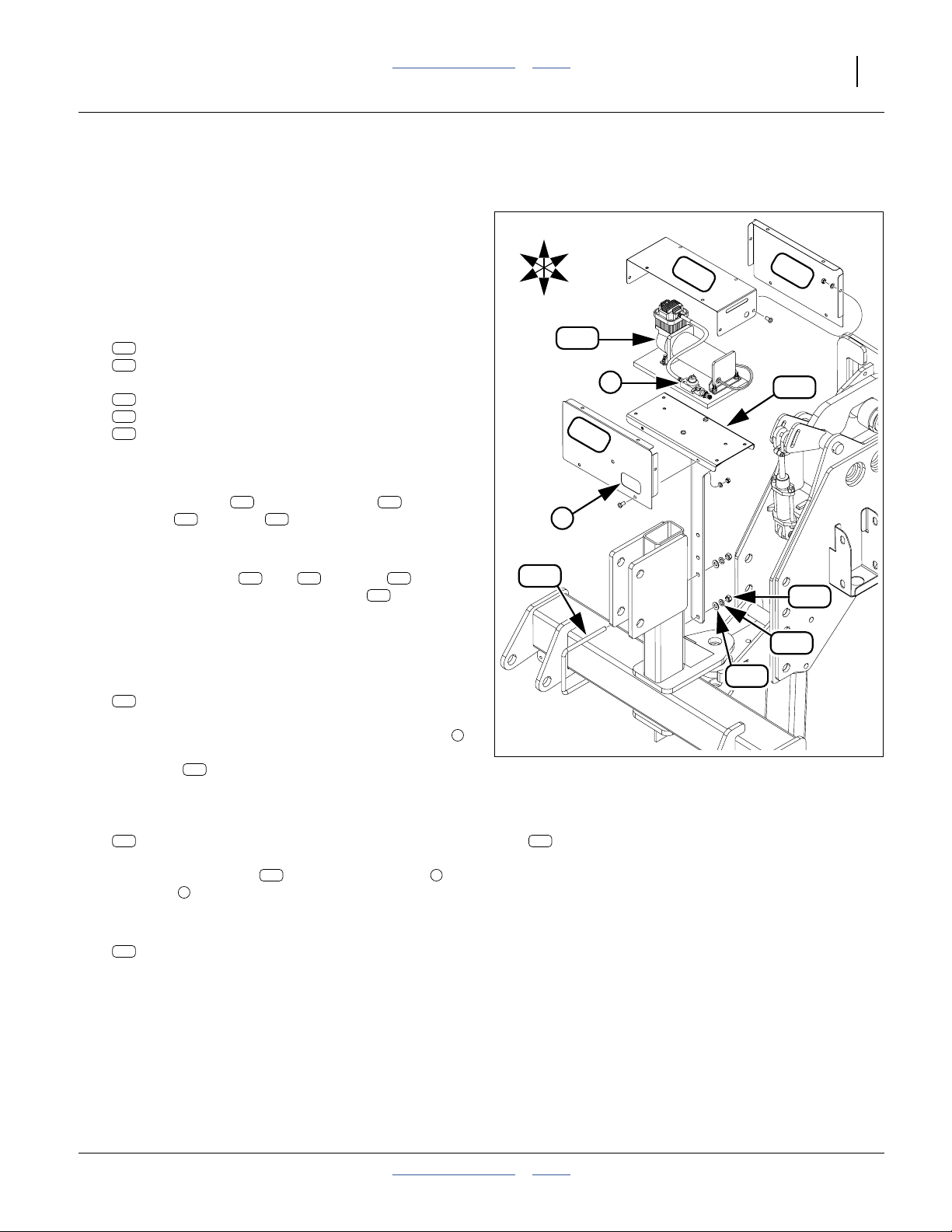
Great Plains Manufacturing, Inc. Table of Contents Index Install Compressor 17
Pull-Type 3-Point Compressor Installation
Note: By convention, the Swath Command™
compressor is installed on the right hand side of the
hitch. If a Row-Pro™ compressor is already
installed there, the Swath Command™
compressor may be installed on the left hand side.
Refer to Figure 16
105. Select one each new:
211
404-861H 12V COMP MOUNT WELDMENT
254
806-060C U-BOLT 1/2-13 X 6 1/32 X 7 1/4
and two sets:
247
804-016C WASHER FLAT 1/2 SAE PLT
246
804-015C WASHER LOCK SPRING 1/2 PLT
239
803-020C NUT HEX 1/2-13 PLT
Place the U-bolt on the 3-point hitch cross-tube, to
the right of the center riser. Loosely secure the
mount weldment with flat washers , lock
washers and nuts . Adjust mount position so
that the left edge of the platform clears the riser by
approximately an inch (5 cm).
106. If the side covers ( and ) and top are
pre-installed on the mount weldment , and the
compressor is not pre-installed, remove the covers,
saving the fasteners.
246 239
211 247
207 208 206
211
Install Compressor (3P)
107. Select one:
263
823-330C TRU-COUNT COMPRESSOR ASSEMBLY
R
F
U
D
254
B
L
263
207
2
206
1
208
211
239
246
247
Orient the compressor assembly so that the valve
is to the front. Secure it to the platform of the mount
weldment using the fasteners provided.
211
1
Figure 16
Pull-Type 3-Point Mount
34076
Install Compressor Covers (3P)
108. Select one:
207
404-226D TC COMPRESSOR COVER SIDE R
Orient the side cover with the access port at
the valve . Loosely secure cover to mount with
provided fasteners.
109. Select one:
208
Loosely secure cover to mount with provided
fasteners.
2012-08-23 Table of Contents Index 402-382M
1
404-227D TC COMPRESSOR COVER SIDE L
207 2
110. Select one:
206
404-225D 12 COMPRESSOR COVER TOP
Completely secure top to side covers with provided
fasteners.
111. Continue at “Install Valve Blocks” on page 19.
Page 22
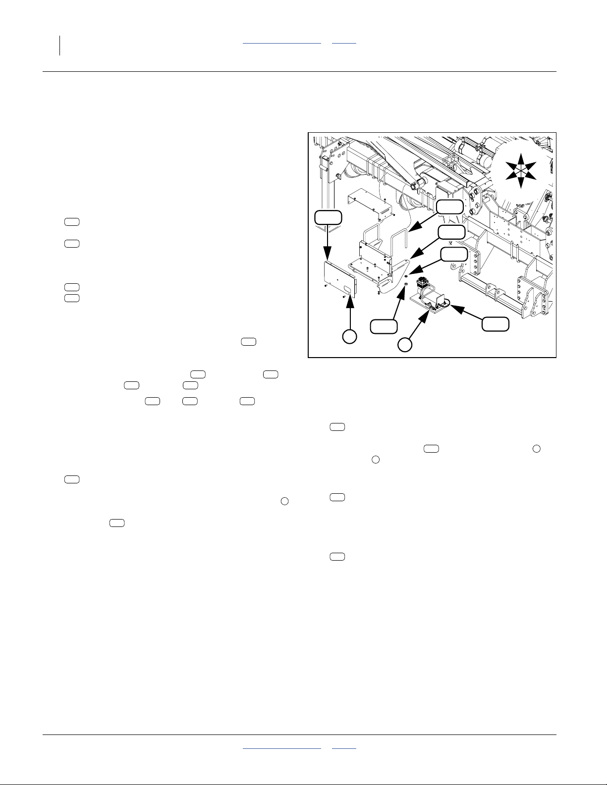
18 Swath Command™ Table of Contents Index Great Plains Manufacturing, Inc.
3PYP and 3PYPA Compressor Installation
Note: By convention, the Swath Command™
compressor is installed on the right hand side of the
hitch. If a Row-Pro™ compressor is already
installed there, the Swath Command™
compressor may be installed on the left hand side.
Refer to Figure 17
112. Select two each new:
253
806-052C U-BOLT 5/8-11 X 7 1/32 X 8 1/2
and two:
210
404-230D COMPRESSOR MOUNT BRACKET
(or the complete mount assembly, if pre-assembled)
and four sets:
248
804-022C WASHER LOCK SPRING 5/8 PLT
240
803-021C NUT HEX 5/8-11 PLT
Find a location on the opener tool bar, right of the
hitch, where the mount assembly clears other
machine parts in front, and the brackets seat
fully against the bottom of the tool bar.
Secure the mount weldment with U-bolts ,
lock washers and nuts .
113. If the side covers ( and ) and top are
pre-installed on the mount assembly, and the
compressor is not pre-installed, remove the covers,
saving the fasteners.
246 239
207 208 206
211 253
210
Install Compressor (3PYP)
114. Select one:
263
823-330C TRU-COUNT COMPRESSOR ASSEMBLY
Orient the compressor assembly so that the valve
is to the front. Secure it to the platform of the mount
weldment using the fasteners provided.
211
253
207
210
240
2
1
Figure 17
3PYP Compressor Mount
Install Compressor Covers (3PYP)
115. Select one:
207
404-226D TC COMPRESSOR COVER SIDE R
207 2
116. Select one:
1
117. Select one:
Orient the side cover with the access port at
the valve . Loosely secure cover to mount with
provided fasteners.
208
Loosely secure cover to mount with provided
fasteners.
206
1
404-227D TC COMPRESSOR COVER SIDE L
404-225D 12 COMPRESSOR COVER TOP
248
R
F
263
U
B
L
D
34077
Completely secure top to side covers with provided
fasteners.
402-382M Table of Contents Index 2012-08-23
Page 23
Great Plains Manufacturing, Inc. Table of Contents Index 19
Install Valve Blocks
Refer to Figure 18
143
255
F
L
U
R
B
D
237
218
237
Figure 18
Valve Block Mount
242
221
242
1
2
195
272
3
4
AIR IN
231
241
34084
The air clutches now installed are controlled by solenoid
valves provided in blocks of 4 valves, each valve
272
controlling a number of rows. A Swath Command™ kit
includes 1, 2 or 3 valve blocks.
a
218
The valves are controlled by a WSMB-TCOM
. Each
TCOM controls up to eight valves. A Swath Command™
kit includes 1 or 2 WSMBs.
Start at the left side of the planter. Install the valve block
and/or TCOM for each section. A section may have both
components or only a valve block.
118. Select all included WSMB-TCOM bundles:
143
402-305K DJ 8 CHANNEL TRU-COUNT MOD ASM
If the kit has more than one, arrange them in serial
number order for installation.
Note: The 402-305K bundle includes:
218
467982000S1 PLNTR CNTRL OUTPUT MODULE(POM)
219
467983505 DJIA OUTPUT HARN 8-CH TRU-COUN
231
802-224C HHCS 1/4-20X1 1/4 GR5
242
804-006C WASHER LOCK SPRING 1/4 PLT
237
803-006C NUT HEX 1/4-20 PLT
Set each harness aside for later installation.
143
219
Note: Connecting WSMBs to the CANbus in serial
218
number order (page 24) causes them to be
correctly ordered by rows when the seed monitor
detects the configuration change.
119. Consult the clutch layout drawing for the kit
(page 48 through page 132). Note locations of any:
272
829-140C TRU-COUNT 75713-00 VALVE ASM
218
467982000S1
PLNTR CNTRL OUTPUT MODULE(POM)
If none, move to the next section.
120. Select one each new:
195
402-533D TRU-COUNT VALVE MODULE BRACKET
255
806-073C U-BOLT 3/8-16 X 7 1/32 X 7 7/8
and two new:
241
803-209C NUT FLANGE LOCK 3/8-16 PLT
At the location shown in the layout, secure the
bracket to the opener tool bar using the
U-bolt and flange lock nuts .
195
255 241
121. If the layout drawing shows a WSMB at the
218
current location, select the:
218
467982000S1 PLNTR CNTRL OUTPUT MODULE(POM)
with the lowest serial number, and two sets:
231
802-224C HHCS 1/4-20X1 1/4 GR5
242
804-006C WASHER LOCK SPRING 1/4 PLT
237
803-006C NUT HEX 1/4-20 PLT
Insert the bolts from the top rear of the
bracket . Add the WSMB , with connectors
195 218
231
toward implement center, and secure with lock
washers and nuts . Tighten nuts only to
242 237
Grade 2 torque specification.
122. Select one new:
272
829-140C TRU-COUNT 75713-00 VALVE ASM
and two sets new:
221
802-004C HHCS 1/4-20X3/4 GR5
242
804-006C WASHER LOCK SPRING 1/4 PLT
237
803-006C NUT HEX 1/4-20 PLT
Orient the valve assembly with the port lettering
272
upright. Secure the valve block to the bracket
with the bolts , lock washers and nuts .
221 242 237
Tighten nuts only to Grade 2 torque specification.
123. Repeat step 119 through step 122 for the next
bracket, if any.
195
a. Working Set MemBer - Planter Output Module
2012-08-23 Table of Contents Index 402-382M
Page 24

20 Swath Command™ Table of Contents Index Great Plains Manufacturing, Inc.
402-382M Table of Contents Index 2012-08-23
Page 25
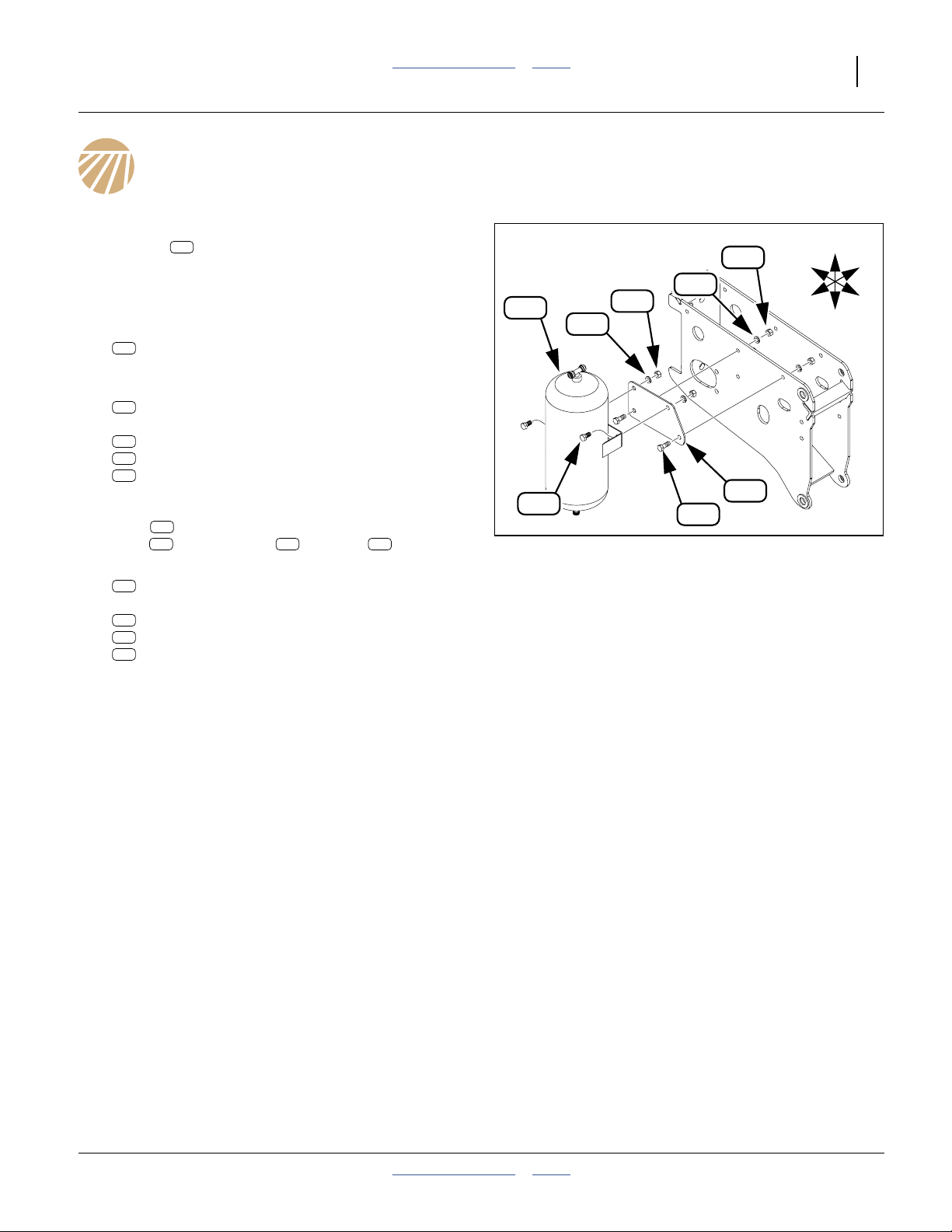
Great Plains Manufacturing, Inc. Table of Contents Index 21
Install Air Tank(s)
Refer to Figure 19
The solenoid valves now installed are supplied by one or
two air tanks .
Start at the left side of the planter. A section may have
one tank or no tank.
124. Consult the clutch layout drawing for the kit
(page 48 through page 132). Note locations of any:
262
If none, move to the next section.
125. Select one each new:
197
and two sets new:
224
245
238
At the location shown in the layout, secure the
plate to the left side of the opener using the
bolts , lock washers and nuts .
126. Select one new:
262
and two sets new:
223
245
238
127. Repeat step 124 through step 126 for the next tank,
if any.
262
823-329C TRU-COUNT AIR TANK ASM
402-535D TRU-COUNT AIR TANK MOUNT PLATE
802-017C HHCS 3/8-16X1 GR5
804-013C WASHER LOCK SPRING 3/8 PLT
803-014C NUT HEX 3/8-16 PLT
197
224 245 238
823-329C TRU-COUNT AIR TANK ASM
802-014C HHCS 3/8-16X3/4 GR5
804-013C WASHER LOCK SPRING 3/8 PLT
803-014C NUT HEX 3/8-16 PLT
262
262
238
245
238
245
197
224
Figure 19
Air Tank Mount
U
F
L
R
B
D
34085
2012-08-23 Table of Contents Index 402-382M
Page 26
22 Swath Command™ Table of Contents Index Great Plains Manufacturing, Inc.
1
2
3
4
AIR IN
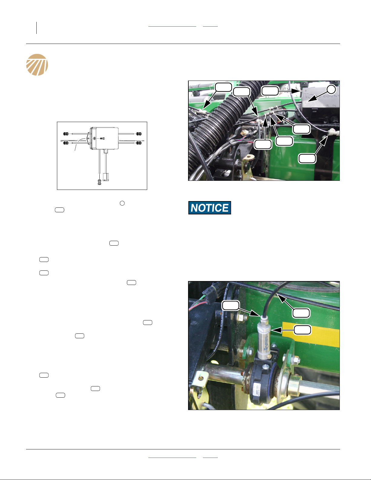
Install Air Lines
Install Row Air Lines
128. Find the Clutch Layout for your planter model (these
are on page 48 through page 132).
Start with the left wing, first clutch and valve Port 1. Valve
ports are numbered 1-4 on the top cover.
34084
Refer to Figure 20
129. Locate the next available port of the valve
272
block .
130. Identify which air clutches are served by that port,
and which clutch is the furthest from the port.
Refer to Figure 21
131. Locate the clutch cylinder to be connected.
132. Select a spool of:
275
990-109R TUBE NYLON 1/4OD X 062WL
and one:
273
830-383C CP 1/4 PUSH LOK POLY
133. Route the tubing from the clutch to the valve
port, passing near each served row clutch. Remain
clear of moving parts. allow enough slack to dress
the tubing against the rear top corner of the tool bar,
and avoid kinking at turns.
Pull the white polymer or metal collars away
from the fitting body. Insert the valve tubing and
clutch tubing . Push together. Re-seat collars.
273
134. At the clutch cylinder, cut the tubing to length. Pull
up collar. Insert tubing. Push together.
135. If the valve port serves more than one clutch, select
one tee for each additional served clutch:
274
830-405C TE POLY 1/4 PUSH LOCK
Cut the tubing just installed, directly above a served
clutch. Insert a tee . Cut a length of fresh
275
tubing to run from the tee to the clutch.
274
Make the connection.
136. Repeat step 129 through step 135 for all used valve
ports and row clutches.
1
278
278
283
273
275
272
1
283
283
273
274
Figure 20
Valve Block Tubing
Tubing Damage Risk:
At section divisions, route the tubing with the existing air hose
and harness bundle, as these pass through a pivot point,
eliminating pull-out risk and minimizing tubing flex. Routing
tubing directly across a wing gap will result in tubing damage
during operation.
34242
283
275
278
Figure 21
Clutch Cylinder Tubing
34242
402-382M Table of Contents Index 2012-08-23
Page 27
Great Plains Manufacturing, Inc. Table of Contents Index Install Air Lines 23
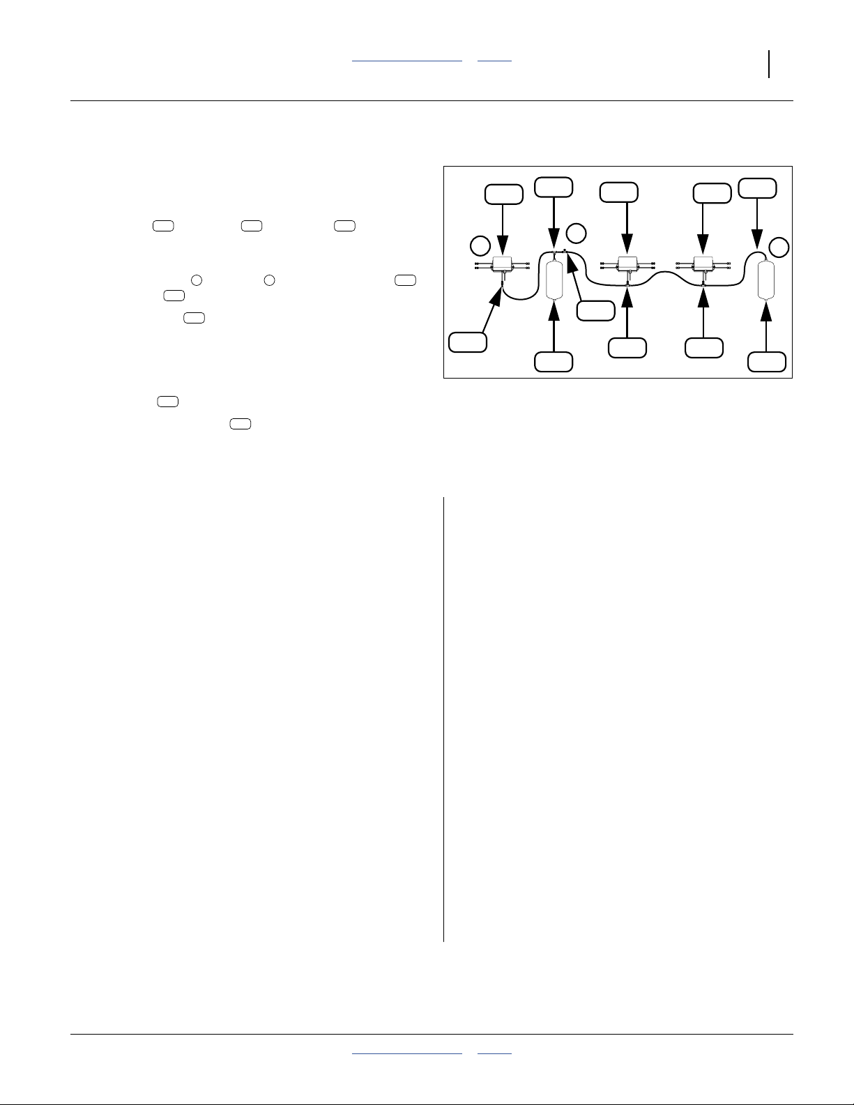
Install Section Air Lines
All of the tanks and valve inlets are interconnected,
forming a single shared reservoir system.
On a smaller planter, this topic is a simple connection of
a single tank and valve . Use a tee at the
inside end of the tubing, for the supply connection.
Refer to Figure 22
137. Locate the left and right extents of the tank
and valve set now installed.
138. Route tubing between these ends. Stay at the
upper rear edge of the tool bar, except at inboard
wing ends. At wing pivots, follow the existing seed
hose and harness bundles.
139. Make end connections using push-lock fittings or
couplers .
140. Select as many tees as needed to make
connections between ends. Select one additional
tee for use as supply line, inserted and connected in
the next topic.
262 272 274
1 3 262
272
275
273
274
272
1
273
274
272
272
2
274
274 274
262 262
Figure 22
Generalized Section Connections
275
3
34245
Install Supply Air Lines
The supply line from the hitch connects to the section
line:
• On a folding planter, the line is routed inside the left
pull bar, and connects to the section line on the left
wing.
• On a 3PYP/A planter, the line is routed from the hitch
and connects to the section line at machine center.
141. Use the final tee to splice into the section line at the
point where the supply line is expected to meet it.
142. Route the remaining tubing from the hitch to the
section connection point.
143. If the compressor is tractor-mounted, cut the supply
line near the hitch and insert a coupler.
144. Connect the end of the supply line to the pump
outlet.
145. Install and secure the compressor cover.
Fish Line Bind
If the wire or tape cannot be fished through the left pull
bar of a folding planter, it is necessary to re-pull the
entire hose/harness bundle, with the tubing added.
a. Connect each hydraulic hose at the hitch to a
hydraulic source that has a Float capability. Set the
circuit to Float to relieve pressure in the hose.
b. Identify each hose inside the left pull bar with tape
and marker. Determine which hose end is easier to
disconnect. Mark the other side of each connection.
c. Carefully crack each JIC connection to relieve any
unexpected residual pressure. Disconnect each
connection and drain it into a bucket.
d. Mark and disconnect any harness routed through
the pull bar.
e. Connect a fish line to the disconnected end of a
hose or harness.
f. Pull the hose and harness bundle out.
g. Add the supply tubing to the bundle.
h. Attach the bundle to the fish line. Pull the bundle
through the pull bar.
i. Re-establish all connections.
j. Perform a bleed before performing any hydraulic
lifts or folds.
2012-08-23 Table of Contents Index 402-382M
Page 28
24 Swath Command™ Table of Contents Index Great Plains Manufacturing, Inc.
Install Harness
Determine Connections
146. Find the Clutch Layout for your planter model
(these are on page 48 through page 132).
Determine which valve is attached to which
WSMB-TCOM , and which outputs of the
WSMB.
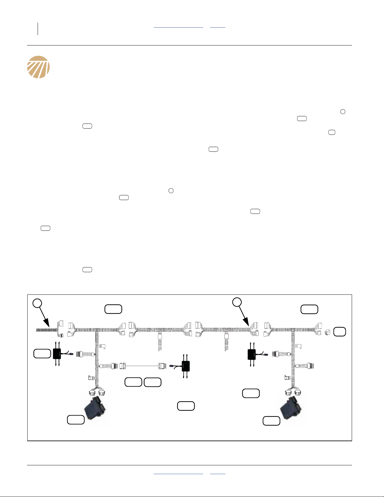
Refer to Figure 23 (which is a generalized layout, and not
specific to any particular kit)
218
Connect WSMB Harnesses
Insert Left Wing WSMB Harness
147. On the left wing, locate a CANbus connection
near the first WSMB-TCOM . This connection
may be from the hitch lead, at the WSMT, or at an
existing WSMB.
148. Select one new:
219
467983505 DJIA OUTPUT HARN 8-CH TRU-COUN
Interconnect the four CANbus connectors into the
existing harness.
Connect the DEUTSCH connectors to the
WSMB-TCOM .
218
218
1
Insert Right Wing WSMB Harness
If your kit only had one WSMB, continue at “Connect
Valve Blocks” on page 25.
149. On the right wing, locate a CANbus connection
near the second WSMB-TCOM . This
connection may be at an existing WSMB, but is
more likely to be at the CANbus terminator .
150. Select one new:
219
467983505 DJIA OUTPUT HARN 8-CH TRU-COUN
Interconnect the four CANbus connectors into the
existing harness. In the case of a terminator
connection, one harness connector is left
unconnected, and the other on that side takes the
terminator.
Connect the DEUTSCH connectors to the
WSMB-TCOM .
218
218
18
1
1
Tru Count
Clutch Harness
467983505
219
2
Tru Count
Clutch Harness
467983505
219
18
CAN
Terminator
272
Tru Count
Solenoid
Module
WP6 Extension
264
265
Tru Count
Solenoid
Module
Tru Count
Solenoid
Module
272
272
218
WSMB
Tru Count
Output Module
Figure 23
Generalized Implement Harness Diagram
402-382M Table of Contents Index 2012-08-23
218
WSMB
Tru Count
Output Module
34246
Page 29

Great Plains Manufacturing, Inc. Table of Contents Index Install Harness 25
Connect Valve Blocks
Connect 1st Valve Block
151. Connect the 6-pin weatherpak connector marked for
outputs 1-4 to the first solenoid valve .
Connect 2nd Valve Block (if any)
152. Move to the next (second) valve. If the valve lead
cannot reach the WSMB to which it is assigned,
select one of:
264
823-336C EXTENSION HARNESS 25’6 PIN WP
265
823-337C EXTENSION HARNESS 40’6 PIN WP
Per the layout, connect the second valve to
WSMB#1 outputs 5-8, or to WSMB#2 outputs 1-4.
Use the extension as needed to make the
connection.
Cable Damage Risk:
If an extension is used, and crosses a wing pivot, route it with
the existing seed hoses, harnesses and air tubing.
272
Connect 3rd Valve Block (if any)
153. Connect the valve lead to the Output 1-4 lead of the
second WSMB.
Secure Tubing and Harnesses
Use cable ties to secure all tubing and harnesses.
Do not install ties in the bend radius at wing pivots.
2012-08-23 Table of Contents Index 402-382M
Page 30
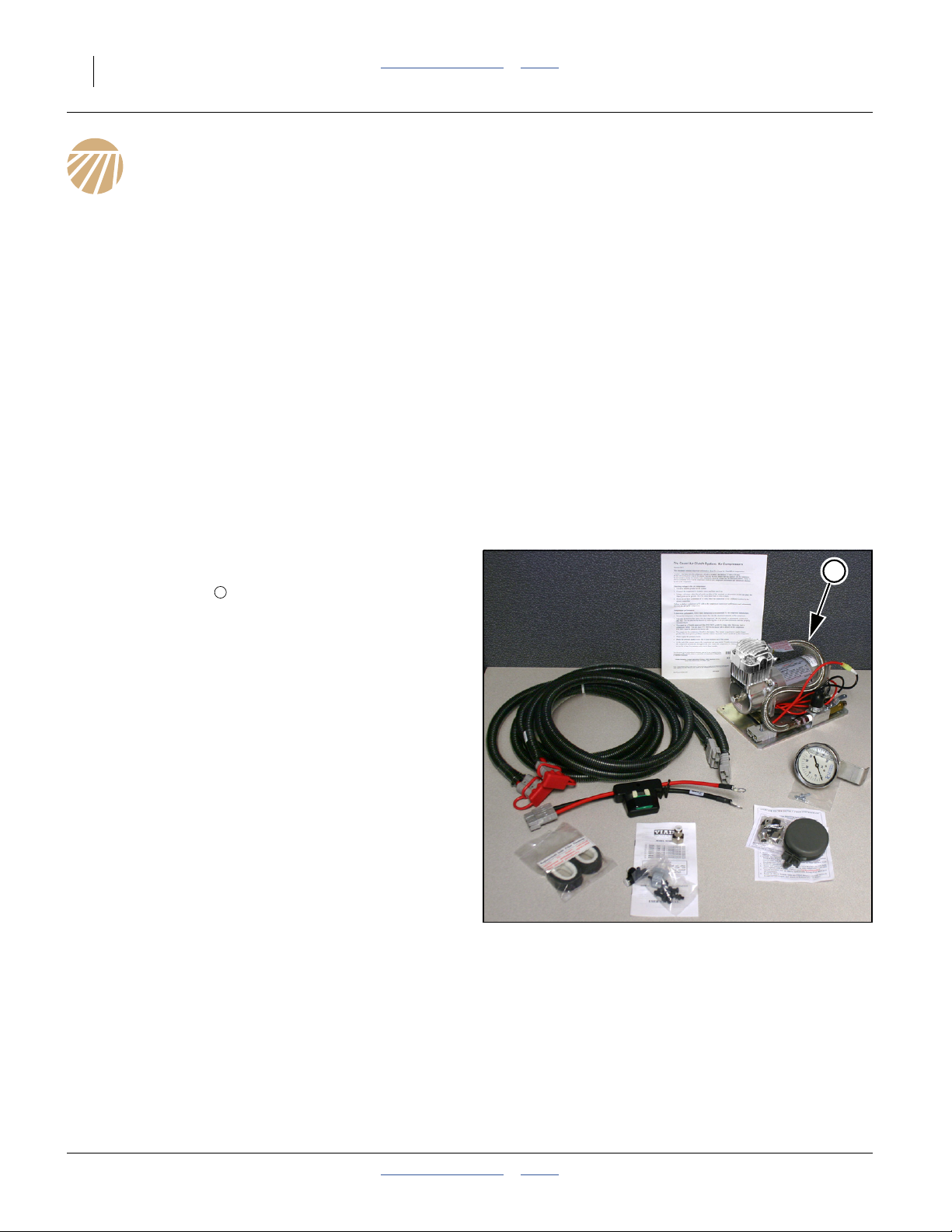
26 Swath Command™ Table of Contents Index Great Plains Manufacturing, Inc.
System Set Up
Implement Considerations
For a standard configuration, no components typically
need to be installed on the planter. Continue at “Install
Satellite Receiver” on page 28.
If after-market clutch control systems are to be used,
consult the supplier documentation for installation.
Unless CANbus compatible electronics are used, such
an installation will involve a harness from the tractor cab
to the planter main frame and tool bars.
Note: Clutch control components not supplied or
recommended by Great Plains may not be
monitored by the DICKEY-john®IntelliAg
system. Row shut-off by a non-standard swath
controller can cause nuisance row-failure alarms.
®
Install Tractor Components
For a standard configuration, using the supplied
compressor pre-installed on the planter, continue at
“Install Cab Components” on page 28.
With an existing air source, continue at “Install Satellite
Receiver” on page 28.
Relocate Standard Compressor
Refer to Figure 24
Plan the compressor re-installation, allowing for a
source of clean air and complying with other compressor
mounting requirements. These instructions presume a
re-installation on the tractor. Factors include:
• Chose a flat surface (base plate down). This may
require purchase or fabrication of a bracket.
• Keep the power leads to the battery as short as
possible. Use only the cabling provided and no
extensions. The voltage measured at the motor must
be 12.0 Vdc or higher, operating under load.
• Chose a compressor mounting location that is away
from heat sources, particularly exhausts and heat
exchanger outflows.
• Avoid locations near flammable liquids. The pump gets
hot. Splashed fuel could be a fire hazard.
• Chose a dry location if possible (this is a MUST if the
inlet filter is pump-mounted). The compressor is
water-resistant but not water-proof. Avoid locations in
the path of water thrown by tires.
• Allow a short inlet air hose run (or no hose at all)
between the compressor inlet and the inlet air filter
(filter MUST be placed at a clean and dry location,
typically the tractor cab). You may need to provide
hose for longer runs.
See the Viair User’s Manual for detailed compressor
installation instructions.
1
Note: If you plan to use an existing air source, it must be
able to provide 1.2 cfm (34 liters/min) at
130 psi (9 bar). The air must also be filtered at a
maximum 10 micron (10 µm) particle size to
prevent fouling of the cylinder breather plugs. An
existing source also needs to be adapted to the
pump outlet or tank inlet (hose size or3⁄8MNPT).
1
Figure 24
823-330C Compressor Kit
Inlet Air Hose Specification
Nylon tubing.1⁄4inch (6.4 mm) OD.1⁄4inch ID. 0.62 inch
wall thickness. 2000 psi.
32221
402-382M Table of Contents Index 2012-08-23
Page 31

Great Plains Manufacturing, Inc. Table of Contents Index System Set Up 27
Mount Pressure Gauge
For a standard configuration, using the supplied
compressor pre-installed on the planter, continue at
“Install Cab Components” on page 28.
Leaky Connect Risk:
When cutting hose, use a sharp knife or scissor-type tubing
cutter. Make the cuts smooth and perpendicular to the length
of the hose. Avoid angled and ragged cuts.
Refer to Figure 25
Find a location for the pressure gauge that is visible
from the tractor cab, but not too far from the routing path
of the air hose from the pump to the solenoid valves on
the planter.
2
Connect Compressor Air Lines
For a standard configuration, using the supplied
compressor pre-installed on the planter, continue at
“Install Cab Components” on page 28.
Refer to Figure 26 (which depicts the gauge on the tractor side
of the hitch connection)
1. Cut hoses to meet at the hitch. Terminate with
mating connectors .
2. Insert a tee in the line near the gauge. Route
hose from tee to gauge.
3. Unless the compressor is mounted inside the tractor
cab, route a hose from the inlet into the cab.
4
3
5
2
7
Figure 25
Compressor Components
Breather Fouling Risk:
Avoid the use of sealant tape on NPT connections. Use liquid
sealant, and avoid application at thread starts. Tape fragments
and uncontained sealant can foul breather plugs, resulting in
seed meters failing to operate.
32221
5
4
Figure 26
Compressor Hose Connections
2012-08-23 Table of Contents Index 402-382M
2
3
32224
Page 32

28 Swath Command™ Table of Contents Index Great Plains Manufacturing, Inc.
Install Satellite Receiver
If the augmented coordinate receiver is already installed,
continue at “Install Cab Components”. Otherwise,
consult the instructions supplied with the primary and
augmentation receiver(s).
The primary, and any augmentation receiver may need to
be configured or programmed via an office computer
prior to mechanical installation.
Receivers are typically mounted on the rear center of the
tractor cab roof. Route cables into the tractor cab.
Note: Mounting a receiver on the planter implement is not
presently recommendedaby Great Plains. Planter
mounting is strongly discouraged if the same
receiver is also used for tractor auto-steer.
Install Cab Components
Install Air Inlet Filter
Refer to Figure 28
4. Verify that the filter housing has a filter element
installed. See item in Figure 25 on page 27
7
5. Unless the filter is mounted directly at the
compressor inlet, use the provided fittings to
connect the filter to the hose run into the cab at
step 3 on page 27.
6
Figure 27
AgGPS®262 on 900 Radio
6
Figure 28
Inlet Filter in Tractor Cab
32220
32217
a. Implement GPS installation requires a location ahead of the seed tubes (not directly above or aft of seed drop point), and above all
implement components, including folded marker discs. This would require a rigid custom platform structure.
402-382M Table of Contents Index 2012-08-23
Page 33

Great Plains Manufacturing, Inc. Table of Contents Index System Set Up 29
Install Control Terminal
Planter Option 57 (AI120) Console
Refer to Figure 29
This console is a complete super-set of any existing
DICKEY-john® AI100 (formerly A1) console that might
be installed. It also performs the combined functions of
and A1 and an A5 console.
Consult the DICKEY-john®Auto Section Control System
Operator’s Manual (
auto section control terminal in the tractor cab. The kit
includes a dual-gimbal RAM mount and fasteners. The
base end of the mount must be dealer- or user-affixed to
a cab location.
View Obstruction Hazard:
Mount the AI120 where it does not block your view of the road
in transport, or block your view of the planter, but can be
easily observed and manipulated in the field.
Continue at topic “Connect Cab Harnesses”.
Field Kit (A5) Console
Refer to Figure 30
Swath Command™ field installation kits are designed to
work with an existing DICKEY-john®AI100 (formerly A1)
10 inch color console. The kits include an auxiliary
DICKEY-john® A5 section control console.
Consult the DICKEY-john®Auto Section Control System
Operator’s Manual (11001-1561A) for installation of the
auto section control terminal in the tractor cab. The kit
includes a dual-gimbal RAM mount and fasteners. The
base end of the mount must be dealer- or user-affixed to
a cab location.
11001-1561A) for installation of the
Figure 29
DICKEY-john® AI120 Terminal Kit
32482
View Obstruction Hazard:
Mount the A5 where it does not block your view of the road in
transport, or block your view of the planter, but can be easily
observed and manipulated in the field.
Connect Cab Harnesses
Planter Option 57 (AI120) Harnesses
Refer to Figure 31 on page 30
Continue at “IntelliAg® PDC Setup” on page 32.
Field Kit (A5) Harnesses
DICKEY-john® A5 Terminal Kit
Figure 30
Refer to Figure 32 on page 31
If using an AgGPS® receiver and DICKEY-john® A5
Terminal, connect them with a 467980458 harness.
2012-08-23 Table of Contents Index 402-382M
32219
Page 34

30 Swath Command™ Table of Contents Index Great Plains Manufacturing, Inc.
Th
System Harness Diagram (Option 57)
This diagram shows the factory-installed configuration,
plus optional GPS receiver.
CFM Switch
Battery
Tractor
Power
Harness
467980455
Tractor A1
Harness
467980451A
Module
CFM to
CAN Harness
467980330
e components changed or added for
Swath Command™ are outlined with dashes.
NOTE: The GPS receiver connects
to the cab harness RS232 port.
Refer to Auto Section Control
Setup to transmit GPS signal
directly over CANbus.
IntelliAg AI120
Virtual Terminal
ISO
Tractor
Hitch
Hitch Extension
Harness
46798013x
Tru Count
Solenoid
Modules
Tractor ECU
Tru Count
Clutch Harness
467983505
Tru Count
Output Module
Master
Switch
WSMT 2 ‘T’ Harness
467980850
WSMB
Figure 31
Option 57 / AI120 Harness Diagram
GPS Receiver
(See Note)
CAN Terminator
WSMT 2
PDC Module
32485
402-382M Table of Contents Index 2012-08-23
Page 35

Great Plains Manufacturing, Inc. Table of Contents Index System Set Up 31
Th
System Harness Diagram (Kit)
This diagram shows a configuration using only
components available through Great Plains.
Battery
Tractor
Power
Harness
467980455
ISO
Tractor
Hitch
Hitch Extension
Harness
46798013x
Auto Section
Control Terminal
Ignition
Auto
Section
Terminal
nterface
Harness
467980458
Tru Count
Clutch Harness
467983505
GPS Receiver
(See Note)
Tractor A1
Harness
467980451A
Tractor ECU
e components changed or added for
Swath Command™ are outlined with dashes.
CFM Switch
Module
CFM to
CAN Harness
467980330
Master
Switch
NOTE: GPS receiver connects
direct to RS232 on Auto Section
Terminal harness. Refer to
Auto Section Control Setup to
transmit GPS signal over CAN.
IntelliAg
Virtual Terminal
Tractor Harness
RS232 (not used with
Auto Section Control
WSMT 2 ‘T’ Harness
467980850
CAN Terminator
Tru Count
Solenoid
Modules
WSMB
Tru Count
Output Module
Figure 32
WSMT 2
PDC Module
32188
Field Kit / A5 Harness Diagram
2012-08-23 Table of Contents Index 402-382M
Page 36

32 Swath Command™ Table of Contents Index Great Plains Manufacturing, Inc.
IntelliAg® PDC Setup
The system needs know where all seed drop points are
located, so that it can accurately turn seeding on and off,
as well as record seeded areas.
Detailed steps are provided in the 403-857M Feature
Operation manual.
The present manual (402-382M Installation and
Reference) provides reference information needed for
console setup.
Figure 33
Swath Command™ Consoles
34255
402-382M Table of Contents Index 2012-08-23
Page 37

Great Plains Manufacturing, Inc. Table of Contents Index 33
Appendix A - Reference Information
Torque Values Chart
Bolt
Size
in-tpi
1
⁄4-20
1
⁄4-28
5
⁄16-18
5
⁄16-24
3
⁄8-16
3
⁄8-24
7
⁄16-14
7
⁄16-20
1
⁄2-13
1
⁄2-20
9
⁄16-12
9
⁄16-18
5
⁄8-11
5
⁄8-18
3
⁄4-10
3
⁄4-16
7
⁄8-9
7
⁄8-14
1-8
1-12
1
⁄8-7
1
1
1
⁄8-12
1
1
⁄4-7
1
1
⁄4-12
3
⁄8-6
1
3
1
⁄8-12
1
1
⁄2-6
1
1
⁄2-12
Bolt Head Identification
Grade 2 Grade 5 Grade 8 Class 5.8 Class 8.8 Class 10.9
a
b
N-m
7.4 11 16
8.5 13 18
15 24 33
17 26 37
27 42 59
31 47 67
43 67 95
49 75 105
66 105 145
75 115 165
95 150 210
105 165 235
130 205 285
150 230 325
235 360 510
260 405 570
225 585 820
250 640 905
340 875 1230
370 955 1350
480 1080 1750
540 1210 1960
680 1520 2460
750 1680 2730
890 1990 3230
1010 2270 3680
1180 2640 4290
1330 2970 4820
d
ft-lb
N-m N-m
5.6 8 12
61014 5 811
11 17 25 12 19 27
13 19 27 13 21 29
20 31 44 24 39 53
22 35 49 29 45 62
32 49 70 42 67 93
36 55 78 44 70 97
49 76 105 66 77 105
55 85 120 68 105 150
70 110 155 73 115 160
79 120 170 105 165 230
97 150 210 115 180 245
110 170 240 145 230 300
170 265 375 165 260 355
190 295 420 205 325 450
165 430 605 230 480 665
185 475 670 355 560 780
250 645 910 390 610 845
275 705 995 705 1120 1550
355 795 1290 785 1240 1710
395 890 1440 1270 1950 2700
500 1120 1820 1380 2190 3220
555 1240 2010
655 1470 2380
745 1670 2710
870 1950 3160
980 2190 3560
Bolt Head Identification
Bolt
Size
ft-lb ft-lb ft-lb ft-lb ft-lb
mm x pitch
M 5 X 0.8
M 6 X 1
M 8 X 1.25
M 8 X 1
M10 X 1.5
M10 X 0.75
M12 X 1.75
M12 X 1.5
M12 X 1
M14 X 2
M14 X 1.5
M16 X 2
M16 X 1.5
M18 X 2.5
M18 X 1.5
M20 X 2.5
M20 X 1.5
M24 X 3
M24 X 2
M30 X 3.5
M30 X 2
M36 X 3.5
M36 X 2
a. in-tpi = nominal thread diameter in inches-threads per inch
b. N· m = newton-meters
c. mm x pitch = nominal thread diameter in mm x thread pitch
d. ft-lb = foot pounds
c
5.8 8.8 10.9
N-m N-m N-m
357
71115
17 26 36
18 28 39
33 52 72
39 61 85
58 91 125
60 95 130
90 105 145
92 145 200
99 155 215
145 225 315
155 240 335
195 310 405
220 350 485
280 440 610
310 650 900
480 760 1050
525 830 1150
960 1510 2100
1060 1680 2320
1730 2650 3660
1880 2960 4100
946
Torque tolerance + 0%, -15% of torquing values. Unless otherwise specified use torque values listed above.
2012-08-23 Table of Contents Index 402-382M
25199
Page 38

34 Swath Command™ Table of Contents Index Great Plains Manufacturing, Inc.
Clutch Exploded Views
823-327Ca Right Hand (RH) Air Clutch
c/o PART NO DESCRIPTION
260
823-327C TRUE COUNT RH AIR CLUTCH
270
823-411C TRUE COUNT CLUTCH HUB RH
276
TC-68553 HOUSING, CLUTCH
277
TC-68824 CYLINDER
278
TC-68824-01 AIR CYLINDER ASSY
279
TC-68831 MUFFLER/FILTER
280
TC-68855 CLUTCH COVER
281
TC-68858 SPRING - RH
283
TC-69002 FITTING, 1/8"MNPT
284
TC-69027 SCREW, PAN 1/4-20 x .375
285
TC-72250 STOP COLLAR
286
TC-72254 RETAINING RING
287
TC-72255 SCREW, 6-32 x .375
288
TC-73183 PIN HUB REGULAR
See manual 403-857M for maintenance and
component orientation details.
278
283
277
279
284
287
280
281
288
Figure 34
823-327C RH Clutch Exploded View
285
270
286
276
U
F
L
R
B
D
32274
a. Parts prefixed “TC-” are original Tru-Count or Trimble part numbers, and must be ordered from Trimble.
Replacement clutch housings may not have a decal with the Great Plains part number.
402-382M Table of Contents Index 2012-08-23
Page 39

Great Plains Manufacturing, Inc. Table of Contents Index Appendix A - Reference Information 35
823-328Ca Left hand (LH) Air Clutch
c/o PART NO DESCRIPTION
261
823-328C TRU-COUNT LH AIR CLUTCH
271
823-412C TRUE COUNT CLUTCH HUB RH
276
TC-68553 HOUSING, CLUTCH
277
TC-68824 CYLINDER
278
TC-68824-01 AIR CYLINDER ASSY
279
TC-68831 MUFFLER/FILTER
280
TC-68855 CLUTCH COVER
282
TC-68879 SPRING - LH
283
TC-69002 FITTING, 1/8"MNPT
284
TC-69027 SCREW, PAN 1/4-20 x .375
285
TC-72250 STOP COLLAR
286
TC-72254 RETAINING RING
287
TC-72255 SCREW, 6-32 x .375
288
TC-73183 PIN HUB REGULAR
See manual 403-857M for maintenance and
component orientation details.
276
278
284
283
277
279
280
288
287
282
286
285
F
271
Figure 35
823-328C LH Clutch Exploded View
a. Parts prefixed “TC-” are original Tru-Count or Trimble part numbers, and must be ordered from Trimble. Replacement clutch housings
may not have a decal with the Great Plains part number.
L
U
R
B
D
32275
2012-08-23 Table of Contents Index 402-382M
Page 40

36 Swath Command™ Table of Contents Index Great Plains Manufacturing, Inc.
402-273K TRU-COUNT SINGLE ROW ASM
106
REF c/o PART NO DESCRIPTION QTY Page
402-273K Single-Row Left Hand
B
192
1 402-529D ADAPTER TC CLUTCH 41A12 SPKT 1
193
2 402-530D TRU-COUNT SPKT RETAINER RING 2
203
3 402-630D SPKT 41A12 3HOLE TC 1
L
230
4 802-167C HHCS 1/4-20X1 1/2 GR5 1
234
5 802-575C HSHCS #10-32X5/8 3
236
6 802-904C HSHCS #10-32X7/8 3
237
7 803-006C NUT HEX 1/4-20 PLT 1
249
8 804-032C WASHER LOCK INTERNAL #10 SS 3
261
9 823-328C TRU-COUNT LH AIR CLUTCH 1 35
U
R
402-382M Table of Contents Index 2012-08-23
D
F
Page 41

Great Plains Manufacturing, Inc. Table of Contents Index Appendix A - Reference Information 37
402-273K-ASY: 402-273K Installation Details
Steps:
Install during shaft re-insertion.
1
Only the shaft secures the clutch to
the opener mount .
An existing bearing is presumed
2
26
to be still installed at the left wall of
the opener mount. If it was removed,
re-install it.
1. Add a lock collar ( or ) to
15 101
shaft before installing the clutch
only if specified on the clutch
layout drawing for your kit and
kit. Not all rows have collars.
Lock collars, if used, may be
101 15
new or saved . Do not
secure set screws until all
clutches are installed and
1
shaft is in its final position.
2. Loop meter drive chain (not
shown) over shaft before adding
clutch.
3. Install clutch with
anti-rotation bolt facing
forward, and air cylinder up.
261
230
278
Loop chain over sprocket while
installing.
2
15
101
c/o PART NO DESCRIPTION Page
402-025S LOCK COLLAR, 7/8 HEX W/ SET SC
15
822-239C PEER 7/8 HEX BRG AND MNT (TYP ROW)
26
101
402-025S LOCK COLLAR, 7/8 HEX W/ SET SC
106
402-273K TRU-COUNT SINGLE ROW ASM 36
230
802-167C HHCS 1/4-20X1 1/2 GR5
261
823-328C TRU-COUNT LH AIR CLUTCH 35
278
TC-68824-01 AIR CYLINDER ASSY
15
101
230
278
26
261
Do not adjust chain slack until
all clutches are installed and
1
shaft is in its final position.
15
4. Add a RH lock collar ( or )
101
if specified.
402-273K-ASY Single-Row LH Clutch Installation Details
1
F
L
Figure 36
U
R
B
D
32205
2012-08-23 Table of Contents Index 402-382M
Page 42

38 Swath Command™ Table of Contents Index Great Plains Manufacturing, Inc.
402-275K TRU-COUNT 15 IN ASM
109
105
188
189
190
191
196
201
224
226
228
236
237
238
242
245
250
251
252
257
258
259
260
1 402-272H TRU-COUNT 15 IN SPKT TUBE 1
2 402-523D OFFSET BRG BRACKET 1
3 402-524D ADAPTER 7/8 HEX 1 1/4 RND BORE 1
4 402-525D TRU-COUNT HUB 1
5 402-527D SPACER PLATE FRT BEARING 2
6 402-534D KEY .250X.125X1.00 RECT 2
7 402-541D SPACER SHIM FRT BRG TRU COUNT 4
8 802-017C HHCS 3/8-16X1 GR5 4
9 802-023C HHCS 3/8-16X1 3/4 GR5 2
10 802-097C HHCS 1/4-20X2 1/2 GR5 1
11 802-904C HSHCS #10-32X7/8 3
12 803-006C NUT HEX 1/4-20 PLT 2
13 803-014C NUT HEX 3/8-16 PLT 6
14 804-006C WASHER LOCK SPRING 1/4 PLT 1
15 804-013C WASHER LOCK SPRING 3/8 PLT 6
16 804-046C WASHER FLAT #10 SAE PLT 3
17 804-054C WASHER LOCK #10 3
18 805-446C GRV PIN 3/16DX1L TYPE H 3
19 808-415C SPKT 41B12 SPCL 2
20 816-648C RUBBER FLG BUSH .189ID.36OD 6
21 817-852C FLG BSHG 30MMX32MMX12MM 1
REF c/o PART NO DESCRIPTION QTY Page
22 823-327C TRUE COUNT RH AIR CLUTCH 1 34
402-275K Two-Row RH 15-Inch
F
R
U
L
D
B
402-382M Table of Contents Index 2012-08-23
Page 43

Great Plains Manufacturing, Inc. Table of Contents Index Appendix A - Reference Information 39
402-275K-ASY: 402-275K Installation Details
Steps:
This installation relocates both original
bearings , presumed to be removed.
1. Add a lock collar ( or ) to shaft before
26
15 101 1
installing the clutch only if specified on the
clutch layout drawing for your planter and kit.
Not all rows may have collars.Do not secure
set screws until all clutches are installed and
1
shaft is in its final position.
2. Mount a saved bearing outside (LH) the
offset bracket , using saved bolts, lock
188
26
washers and nuts.
3. If the clutch is not attached to the offset
bracket, insert bolt through the
anti-rotation foot. Add a jam nut . Insert
260
228
237
the bolt end through the bracket. Add a lock
washer and another nut . Tighten
242 237
nuts only to Grade 2 torque.
4. Insert the clutch assembly through the
left side of the long mount . Loop meter
109
2
chains for both rows (not shown) over clutch
tube. Secure bracket with two sets
224 245 238
bolts , lock washers and nuts .
188
Do not adjust chain slack until all clutches are
installed and shaft is in its final position.
5. Re-install bearing inside right mount , using
a combination of spacer plates ( and )
1
3
191
201
as needed to allow clutch assembly
0.060 to 0.120 inches (1.5-3 mm) travel
between the two bearings . Secure with
new bolts , lock washers and
nuts .
6. Adjust sprockets on tube for
226 245
238
257
26
0.75 inch (19 mm) distance
from inside left wall of opener mount to
center-line of sprocket teeth.
7. Add a RH lock collar ( or ) if specified.
15 101
c/o PART NO DESCRIPTION Page
402-025S LOCK COLLAR, 7/8 HEX W/ SET SC
15
822-239C PEER 7/8 HEX BRG AND MNT (TYP ROW)
26
101
402-025S LOCK COLLAR, 7/8 HEX W/ SET SC
109
402-275K TRU-COUNT 15 IN ASM 38
188
402-523D OFFSET BRG BRACKET
191
402-527D SPACER PLATE FRT BEARING
201
402-541D SPACER SHIM FRT BRG TRU COUNT
224
802-017C HHCS 3/8-16X1 GR5
226
802-023C HHCS 3/8-16X1 3/4 GR5
228
802-097C HHCS 1/4-20X2 1/2 GR5
237
803-006C NUT HEX 1/4-20 PLT
238
803-014C NUT HEX 3/8-16 PLT
242
804-006C WASHER LOCK SPRING 1/4 PLT
245
804-013C WASHER LOCK SPRING 3/8 PLT
257
808-415C SPKT 41B12 SPCL
260
823-327C TRUE COUNT RH AIR CLUTCH 34
238
245
3
26
226
201
228
238
191
245
15
101
237
224
188
257
260
Figure 37
257
109
U
F
2
L
R
B
D
32206
15
242
237
26
101
1
402-275K-ASY Two-Row 15 Inch (RH Clutch) Installation Details
2012-08-23 Table of Contents Index 402-382M
Page 44

40 Swath Command™ Table of Contents Index Great Plains Manufacturing, Inc.
402-276K TRU-COUNT 15 IN LH ASM
111
105
189
190
191
194
196
199
201
224
228
233
236
237
238
245
250
251
252
257
258
259
261
1 402-272H TRU-COUNT 15 IN SPKT TUBE 1
2 402-524D ADAPTER 7/8 HEX 1 1/4 RND BORE 1
3 402-525D TRU-COUNT HUB 1
4 402-527D SPACER PLATE FRT BEARING 3
5 402-532D OFFSET BRG BRACKET LH 1
6 402-534D KEY .250X.125X1.00 RECT 2
7 402-539D STEP BUSHING FOR OPENER BRG 2
8 402-541D SPACER SHIM FRT BRG TRU COUNT 4
9 802-017C HHCS 3/8-16X1 GR5 4
10 802-097C HHCS 1/4-20X2 1/2 GR5 1
11 802-382C HHCS 3/8-16X2 1/4 GR5 2
12 802-904C HSHCS #10-32X7/8 3
13 803-006C NUT HEX 1/4-20 PLT 2
14 803-014C NUT HEX 3/8-16 PLT 6
15 804-013C WASHER LOCK SPRING 3/8 PLT 6
16 804-046C WASHER FLAT #10 SAE PLT 3
17 804-054C WASHER LOCK #10 3
18 805-446C GRV PIN 3/16DX1L TYPE H 3
19 808-415C SPKT 41B12 SPCL 2
20 816-648C RUBBER FLG BUSH .189ID.36OD 6
21 817-852C FLG BSHG 30MMX32MMX12MM 1
REF c/o PART NO DESCRIPTION QTY Page
22 823-328C TRU-COUNT LH AIR CLUTCH 1 35
402-276K Two-Row LH 15-Inch
B
L
U
R
402-382M Table of Contents Index 2012-08-23
D
F
Page 45

Great Plains Manufacturing, Inc. Table of Contents Index Appendix A - Reference Information 41
402-276K-ASY: 402-276K Installation Details
Steps:
This installation relocates both original bearings ,
26
presumed to be removed.
1. Add a lock collar ( or ) to shaft before
15 101 1
installing the clutch only if specified on the clutch
layout drawing for your planter and kit. Not all rows
have collars. Secure set screws after all clutches are
installed and shaft is in its final position.
2. Mount saved bearing outside (RH) offset
bracket , using saved bolts, lock washers and
194
1
26
nuts.
3. If the clutch is not attached to the offset bracket,
insert bolt through the anti-rotation foot. Add a
jam nut . Insert the bolt end through the bracket.
Add a lock washer and another nut . Tighten
261
228
237
242 237
nuts only to Grade 2 torque.
4. Insert the clutch assembly through the right side of
the long mount . Loop meter chains for both rows
(not shown) over clutch tube. Secure bracket with
two sets bolts , lock washers and nuts .
2
188
224 245 238
Do not adjust chain slack until all clutches are
installed and shaft is in its final position.
5. Re-install bearing outside left mount , using a step
bushing and a combination of spacer plates
191 201
( and ) as needed to allow clutch assembly
199
1
3
0.060 to 0.120 inches (1.5-3 mm) travel between
the two bearings . Secure with new bolts , lock
washers and nuts .
245 238
6. Adjust sprockets on tube for
26 226
257
0.75 inch (19 mm) distance from inside left wall of
opener mount to center-line of sprocket teeth.
7. Insert shaft through both bearings and
1
the clutch assembly.
8. Add a RH lock collar ( or )
15 101
if specified.
c/o PART NO DESCRIPTION Page
402-025S LOCK COLLAR, 7/8 HEX W/ SET SC
15
822-239C PEER 7/8 HEX BRG AND MNT (TYP ROW)
26
101
402-025S LOCK COLLAR, 7/8 HEX W/ SET SC
111
402-276K TRU-COUNT 15 IN LH ASM 40
191
402-527D SPACER PLATE FRT BEARING
194
402-532D OFFSET BRG BRACKET LH
199
402-539D STEP BUSHING FOR OPENER BRG
201
402-541D SPACER SHIM FRT BRG TRU COUNT
224
802-017C HHCS 3/8-16X1 GR5
226
802-023C HHCS 3/8-16X1 3/4 GR5
228
802-097C HHCS 1/4-20X2 1/2 GR5
237
803-006C NUT HEX 1/4-20 PLT
238
803-014C NUT HEX 3/8-16 PLT
242
804-006C WASHER LOCK SPRING 1/4 PLT
245
804-013C WASHER LOCK SPRING 3/8 PLT
257
808-415C SPKT 41B12 SPCL
261
823-328C TRU-COUNT LH AIR CLUTCH 35
15
26
101
237
242
237
261
228
224
194
257
191
257
111
201
245
238
10115
26
1
402-275K-ASY Two-Row 15 Inch (LH Clutch) Installation Details
2012-08-23 Table of Contents Index 402-382M
3
Figure 38
224
199
238
245
2
U
F
L
R
B
D
32207
Page 46

42 Swath Command™ Table of Contents Index Great Plains Manufacturing, Inc.
402-279K Twin-Row (RH Clutch)
402-279K TRU-COUNT TR ASM
115
114
188
189
1 402-278H TRU-COUNT TR SPKT TUBE REP 1
2 402-523D OFFSET BRG BRACKET 1
B
3 402-524D ADAPTER 7/8 HEX 1 1/4 RND BORE 1
L
REF c/o PART NO DESCRIPTION QTY Page
U
R
F
190
4 402-525D TRU-COUNT HUB 1
D
191
5 402-527D SPACER PLATE FRT BEARING 2
196
6 402-534D KEY .250X.125X1.00 RECT 2
201
7 402-541D SPACER SHIM FRT BRG TRU COUNT 4
224
8 802-017C HHCS 3/8-16X1 GR5 4
226
9 802-023C HHCS 3/8-16X1 3/4 GR5 2
228
10 802-097C HHCS 1/4-20X2 1/2 GR5 1
236
11 802-904C HSHCS #10-32X7/8 3
237
12 803-006C NUT HEX 1/4-20 PLT 2
238
13 803-014C NUT HEX 3/8-16 PLT 6
242
14 804-006C WASHER LOCK SPRING 1/4 PLT 1
245
15 804-013C WASHER LOCK SPRING 3/8 PLT 6
250
16 804-046C WASHER FLAT #10 SAE PLT 3
251
17 804-054C WASHER LOCK #10 3
252
18 805-446C GRV PIN 3/16DX1L TYPE H 3
257
19 808-415C SPKT 41B12 SPCL 2
258
20 816-648C RUBBER FLG BUSH .189ID.36OD 6
259
21 817-852C FLG BSHG 30MMX32MMX12MM 1
261
22 823-328C TRU-COUNT LH AIR CLUTCH 1 35
402-382M Table of Contents Index 2012-08-23
Page 47

Great Plains Manufacturing, Inc. Table of Contents Index Appendix A - Reference Information 43
402-279K-ASY: 402-279K Installation Details
Steps:
This installation relocates both original bearings ,
26
presumed to be removed.
1. Add a lock collar ( or ) to shaft before
15 101 1
installing the clutch only if specified on the clutch
layout drawing for your planter and kit. Not all rows
may have collars.Do not secure set screws until all
clutches are installed and shaft is in its final
1
position.
2. Mount a saved bearing outside (LH) the offset
bracket , using saved bolts, lock washers and
188
26
nuts.
3. If the clutch is not attached to the offset bracket,
insert bolt through the anti-rotation foot. Add a
jam nut . Insert the bolt end through the bracket.
Add a lock washer and another nut . Tighten
260
228
237
242 237
nuts only to Grade 2 torque.
4. Insert the clutch assembly through the left side
of the long mount . Loop meter chains for both
2
115
rows (not shown) over clutch tube. Secure
bracket with two sets bolts , lock
washers and nuts .
188
245 238
224
Do not adjust chain slack until all clutches are
191
1
3
4
201
installed and shaft is in its final position.
5. Re-install bearing inside right mount , on right side
of bearing support plate , using a combination of
spacer plates ( and ) as needed to allow
clutch assembly
0.060 to 0.120 inches (1.5-3 mm) travel between
the two bearings . Secure with new bolts , lock
washers and nuts .
245 238
6. Adjust sprockets on tube for
26 226
257
0.75 inch (19 mm) distance
from inside left wall of opener mount to center-line of
sprocket teeth.
7. Add a RH lock collar ( or ) if specified.
15 101
c/o PART NO DESCRIPTION Page
402-025S LOCK COLLAR, 7/8 HEX W/ SET SC
15
822-239C PEER 7/8 HEX BRG AND MNT (TYP ROW)
26
101
402-025S LOCK COLLAR, 7/8 HEX W/ SET SC
115
402-279K TRU-COUNT TR ASM 40
188
402-523D OFFSET BRG BRACKET
191
402-527D SPACER PLATE FRT BEARING
201
402-541D SPACER SHIM FRT BRG TRU COUNT
224
802-017C HHCS 3/8-16X1 GR5
226
802-023C HHCS 3/8-16X1 3/4 GR5
228
802-097C HHCS 1/4-20X2 1/2 GR5
237
803-006C NUT HEX 1/4-20 PLT
238
803-014C NUT HEX 3/8-16 PLT
242
804-006C WASHER LOCK SPRING 1/4 PLT
245
804-013C WASHER LOCK SPRING 3/8 PLT
257
808-415C SPKT 41B12 SPCL
260
823-327C TRUE COUNT RH AIR CLUTCH 34
238
245
3
226
201
228
191
4
15
101
26
257
238
245
237
224
188
26
15
242
237
101
1
Figure 39
402-279K-ASY Twin-Row (RH Clutch) Installation Details
2012-08-23 Table of Contents Index 402-382M
257
260
115
U
F
2
L
R
B
D
32208
Page 48

44 Swath Command™ Table of Contents Index Great Plains Manufacturing, Inc.
402-281K Twin-Row Reverse (LH Clutch)
402-281K TRU-COUNT TR REVERSE ASM
118
117
189
190
191
196
198
199
1 402-280H TRU-COUNT TR REVERSE SPKT TUBE 1
2 402-524D ADAPTER 7/8 HEX 1 1/4 RND BORE 1
3 402-525D TRU-COUNT HUB 1
4 402-527D SPACER PLATE FRT BEARING 2
5 402-534D KEY .250X.125X1.00 RECT 2
6 402-538D SUPT BRACKET HEX BRG 1
REF c/o PART NO DESCRIPTION QTY Page
B
L
7 402-539D STEP BUSHING FOR OPENER BRG 2
201
8 402-541D SPACER SHIM FRT BRG TRU COUNT 4
222
9 802-005C HHCS 1/4-20X1 GR5 1
224
10 802-017C HHCS 3/8-16X1 GR5 2
225
11 802-022C HHCS 3/8-16X1 1/2 GR5 2
226
12 802-023C HHCS 3/8-16X1 3/4 GR5 2
236
13 802-904C HSHCS #10-32X7/8 3
237
14 803-006C NUT HEX 1/4-20 PLT 1
238
15 803-014C NUT HEX 3/8-16 PLT 6
244
16 804-012C WASHER FLAT 3/8 SAE PLT 2
245
17 804-013C WASHER LOCK SPRING 3/8 PLT 6
250
18 804-046C WASHER FLAT #10 SAE PLT 3
251
19 804-054C WASHER LOCK #10 3
252
20 805-446C GRV PIN 3/16DX1L TYPE H 3
257
21 808-415C SPKT 41B12 SPCL 2
258
22 816-648C RUBBER FLG BUSH .189ID.36OD 6
259
23 817-852C FLG BSHG 30MMX32MMX12MM 1
261
24 823-328C TRU-COUNT LH AIR CLUTCH 1 35
U
R
402-382M Table of Contents Index 2012-08-23
D
F
Page 49

Great Plains Manufacturing, Inc. Table of Contents Index Appendix A - Reference Information 45
402-281K-ASY: 402-281K Installation Details
Steps:
This installation relocates both original bearings ,
26
presumed to be removed.
1. Add a lock collar ( or ) to shaft before
15 101 1
installing the clutch only if specified on the clutch
layout drawing for your planter and kit. Not all rows
have collars. Do not secure set screws until all
clutches are installed and shaft is in its final
1
position.
2. Mount the support bracket to the RH side of the
front (right) opener mount, using two new bolts ,
flat washers step bushings , lock washers
and nuts .
3. Add a bearing to the shaft . Slide the shaft into
244 199 245
238
26 1
the left opener mount . Loop meter chain (not
198
225
2
shown) onto shaft.
4. Mount a saved bearing inside the right bracket,
using new bolts , lock washers and nuts .
224 245 238
5. Slide the clutch assembly , with the clutch to the
26
261
right into the right opener chain (not shown), and
then the right side of the left opener, and onto the
shaft.
6. Slide the shaft through clutch and into the bearing.
7. Re-install bearing outside left mount , using a
combination of spacer plates ( and ) as
191
3
201
needed to allow clutch assembly
0.060 to 0.120 inches (1.5-3 mm) travel between
the two bearings . Secure with new bolts , lock
washers and nuts .
245 238
8. Adjust sprockets on tube for
26 226
257
0.75 inch (19 mm) distance from inside left wall of
opener mount to center-line of sprocket teeth.
9. Add a RH lock collar ( or ) if specified.
15 101
c/o PART NO DESCRIPTION Page
402-025S LOCK COLLAR, 7/8 HEX W/ SET SC
15
822-239C PEER 7/8 HEX BRG AND MNT (TYP ROW)
26
101
402-025S LOCK COLLAR, 7/8 HEX W/ SET SC
118
402-281K TRU-COUNT TR REVERSE ASM 44
191
402-527D SPACER PLATE FRT BEARING
198
402-538D SUPT BRACKET HEX BRG
199
402-539D STEP BUSHING FOR OPENER BRG
201
402-541D SPACER SHIM FRT BRG TRU COUNT
222
802-005C HHCS 1/4-20X1 GR5
224
802-017C HHCS 3/8-16X1 GR5
225
802-022C HHCS 3/8-16X1 1/2 GR5
226
802-023C HHCS 3/8-16X1 3/4 GR5
238
803-014C NUT HEX 3/8-16 PLT
244
804-012C WASHER FLAT 3/8 SAE PLT
245
804-013C WASHER LOCK SPRING 3/8 PLT
257
808-415C SPKT 41B12 SPCL
261
823-328C TRU-COUNT LH AIR CLUTCH 35
225
244
3
245
238
199
222
238
245
198
224
15
101
26
261
257
226
257
118
26
191
1
101
15
238
201
245
2
Figure 40
402-281K-ASY Twin Row Reverse (LH Clutch) Installation Details
2012-08-23 Table of Contents Index 402-382M
U
F
L
R
B
D
32209
Page 50

46 Swath Command™ Table of Contents Index Great Plains Manufacturing, Inc.
402-329K Single-Row Short Mount (RH Clutch)
402-329K TRU-COUNT SHORT ROW SINGLE ASM
144
193
202
1 402-530D TRU-COUNT SPKT RETAINER RING 2
B
2 402-591D SPACER EXTENDED SNGL CLUTCH TC 1
L
REF c/o PART NO DESCRIPTION QTY Page
203
3 402-630D SPKT 41A12 3HOLE TC 1
229
4 802-152C HHCS 1/4-20X2 GR5 1
234
5 802-575C HSHCS #10-32X5/8 3
235
6 802-901C HSHCS #10-32X1 3
237
7 803-006C NUT HEX 1/4-20 PLT 1
251
8 804-054C WASHER LOCK #10 3
260
9 823-327C TRUE COUNT RH AIR CLUTCH 1 34
U
R
402-382M Table of Contents Index 2012-08-23
D
F
Page 51

Great Plains Manufacturing, Inc. Table of Contents Index Appendix A - Reference Information 47
402-329K-ASY: 402-329K Installation Details
Steps:
This installation presumes that the original bearing
is still in place.
1. Add a lock collar ( or ) to that shaft
before installing the clutch. Do not secure set
screws until all clutches are installed and shaft
is in its final position.
2. Add the clutch assembly to the shaft, with
anti-rotation bolt forward and the cylinder
up. Loop meter chain (not shown) over sprocket
on clutch.
3. Loosen the nuts securing the bearing
flangettes at the bearing support plate.
4. Slide the shaft through the bearing.
5. Add a RH lock collar ( or ) if specified on
the clutch layout drawing.
26
15 101 1
260
229 278
15 101
26
c/o PART NO DESCRIPTION Page
402-025S LOCK COLLAR, 7/8 HEX W/ SET SC
15
822-239C PEER 7/8 HEX BRG AND MNT (TYP ROW)
26
101
402-025S LOCK COLLAR, 7/8 HEX W/ SET SC
144
402-329K TRU-COUNT SHORT ROW SINGLE ASM 46
260
1
823-327C TRUE COUNT RH AIR CLUTCH 34
278
TC-68824-01 AIR CYLINDER ASSY
U
F
L
R
B
D
278
229
15
101
1
144
260
15
101
26
Figure 41
402-329K-ASY Single-Row Short Mount (RH Clutch) Installation Details
32210
2012-08-23 Table of Contents Index 402-382M
Page 52

48 Swath Command™ Table of Contents Index Great Plains Manufacturing, Inc.
Swath Command™ Planter Clutch Layouts
Kit: 402-375A Clutch Layout: YP4025, 31-Row
Layout applies to Planter Models: YP4025-3115, YP4025A-3115
Layout also applies to Option 57 factory bundle: 402-277A
Row Clutch Connections Map
Row
Section Left Wing Center Right Wing
CFM Switch 1/Left 2/Center 3/Right
WSMB-TCOM Left Wing WSMB-TCOM
TCOM Output Out 1 Out 2 Out 3 Out 4 Out 5 Out 6 Out 7 Out 8
Valve Block Left Wing Valve Block Right Wing Valve Block
Valve Port V1 V2 V3 V4 V1 V2 V3 V4
Te e
Clutch No. 1 2 3 4 5 6 7 8 9 10 11 12 13 14 15 16
Clutch Type
Row
01 02 03 04 05 06 07 08 09 10 11 12 13 14 15 16 17 18 19 20 21 22 23 24 25 26 27 28 29 30 31
TTTTTTTT
402-275K||402-275K||402-275K||402-275K||402-275K||402-275K||402-275K||402-275K||402-275K||402-275K||402-273K||402-276K||402-276K||402-276K||402-276K||402-276K
01 02 03 04 05 06 07 08 09 10 11 12 13 14 15 16 17 18 19 20 21 22 23 24 25 26 27 28 29 30 31
U
L
R
D
Figure 42
LH: Kit: 402-375A Clutch Layout: YP4025, 31-Row
402-382M Table of Contents Index 2012-08-23
402-277A
Page 53

Great Plains Manufacturing, Inc. Table of Contents Index Appendix A - Reference Information 49
REF c/o PART NO DESCRIPTION
101
1 402-025S LOCK COLLAR, 7/8 HEX W/ SET SC
106
2 402-273K TRU-COUNT SINGLE ROW ASM
109
3 402-275K TRU-COUNT 15 IN ASM
111
4 402-276K TRU-COUNT 15 IN LH ASM
143
5 402-305K DJ 8 CHANNEL TRU-COUNT MOD ASM
195
6 402-533D TRU-COUNT VALVE MODULE BRACKET
197
7 402-535D TRU-COUNT AIR TANK MOUNT PLATE
204
8 403-857M MANUAL YP TRU COUNT OPERATOR
212
9 404-863K TRU-COUNT COMP MOUNT ASM
221
10 802-004C HHCS 1/4-20X3/4 GR5
223
11 802-014C HHCS 3/8-16X3/4 GR5
224
12 802-017C HHCS 3/8-16X1 GR5
237
13 803-006C NUT HEX 1/4-20 PLT
238
14 803-014C NUT HEX 3/8-16 PLT
241
15 803-209C NUT FLANGE LOCK 3/8-16 PLT
243
16 804-007C WASHER FLAT 1/4 SAE PLT
243
17 804-013C WASHER FLAT 1/4 SAE PLT
255
18 806-073C U-BOLT 3/8-16 X 7 1/32 X 7 7/8
256
19 808-309C SPKT 50C25 X 7/8 HEX BORE
262
20 823-329C TRU-COUNT AIR TANK ASM
263
21 823-330C TRU-COUNT COMPRESSOR ASSEMBLY
265
22 823-337C EXTENSION HARNESS 40’6 PIN WP
272
23 829-140C TRU-COUNT 75713-00 VALVE ASM
273
24 830-383C CP 1/4 PUSH LOK POLY
274
25 830-405C TE POLY 1/4 PUSH LOCK
275
26 990-109R TUBE NYLON 1/4OD X 062WL
Figure 43
402-277A
RH: Kit: 402-375A Clutch Layout: YP4025, 31-Row
2012-08-23 Table of Contents Index 402-382M
Page 54

50 Swath Command™ Table of Contents Index Great Plains Manufacturing, Inc.
Kit: 402-376A Clutch Layout: YP4025, 32 Twin Row
Layout applies to Planter Models: YP4025-32TR, YP4025-32TR70, YP4025A-32TR, YP4025A-32TR70
Layout also applies to Option 57 factory bundle: 402-282A
Row Clutch Connections Map
Row
Section Left Wing Center Right Wing
CFM Switch 1/Left 2/Center 3/Right
WSMB-TCOM Left Wing WSMB-TCOM
TCOM Output Out 1 Out 2 Out 3 Out 4 Out 5 Out 6 Out 7 Out 8
Valve Block Left Wing Valve Block Right Wing Valve Block
Valve, Port V1 V2 V3 V4 V 1 V2 V3 V4
Te e
Clutch 12345678910111213141516
01 02 03 04 05 06 07 08 09 10 11 12 13 14 15 16 17 18 19 20 21 22 23 24 25 26 27 28 29 30 31 32
TTTTTTTT
Clutch Type
Row
||
402-281K
402-279K||402-279K||402-279K||402-279K
01 02 03 04 05 06 07 08 09 10 11 12 13 14 15 16 17 18 19 20 21 22 23 24 25 26 27 28 29 30 31 32
||
||
402-281K
402-279K||402-279K||402-279K||402-279K||402-279K||402-279K||402-279K||402-279K||402-279K||402-279K
U
L
R
D
||
Figure 44
402-282A
LH: Kit: 402-376A Clutch Layout: YP4025, 32 Twin Row
402-382M Table of Contents Index 2012-08-23
Page 55

Great Plains Manufacturing, Inc. Table of Contents Index Appendix A - Reference Information 51
REF c/o PART NO DESCRIPTION
101
1 402-025S LOCK COLLAR, 7/8 HEX W/ SET SC
115
2 402-279K TRU-COUNT TR ASM
118
3 402-281K TRU-COUNT TR REVERSE ASM
143
4 402-305K DJ 8 CHANNEL TRU-COUNT MOD ASM
195
5 402-533D TRU-COUNT VALVE MODULE BRACKET
197
6 402-535D TRU-COUNT AIR TANK MOUNT PLATE
204
7 403-857M MANUAL YP TRU COUNT OPERATOR
212
8 404-863K TRU-COUNT COMP MOUNT ASM
221
9 802-004C HHCS 1/4-20X3/4 GR5
223
10 802-014C HHCS 3/8-16X3/4 GR5
224
11 802-017C HHCS 3/8-16X1 GR5
237
12 803-006C NUT HEX 1/4-20 PLT
238
13 803-014C NUT HEX 3/8-16 PLT
241
14 803-209C NUT FLANGE LOCK 3/8-16 PLT
243
15 804-007C WASHER FLAT 1/4 SAE PLT
243
16 804-013C WASHER FLAT 1/4 SAE PLT
255
17 806-073C U-BOLT 3/8-16 X 7 1/32 X 7 7/8
256
18 808-309C SPKT 50C25 X 7/8 HEX BORE
262
19 823-329C TRU-COUNT AIR TANK ASM
263
20 823-330C TRU-COUNT COMPRESSOR ASSEMBLY
265
21 823-337C EXTENSION HARNESS 40’6 PIN WP
272
22 829-140C TRU-COUNT 75713-00 VALVE ASM
274
23 830-405C TE POLY 1/4 PUSH LOCK
275
24 990-109R TUBE NYLON 1/4OD X 062WL
Figure 45
402-282A
RH: Kit: 402-376A Clutch Layout: YP4025, 32 Twin Row
2012-08-23 Table of Contents Index 402-382M
Page 56

52 Swath Command™ Table of Contents Index Great Plains Manufacturing, Inc.
Kit: 402-377A Clutch Layout: YP4025, 16 Row
Layout applies to Planter Models:
YP4025-1630, YP4025-1670, YP4025A-1630, YP4025AF-1670, YP4025F-1630, YP4025F-1670
Layout also applies to Option 57 factory bundle: 402-283A
Row Clutch Connections Map
Row 01020304050607080910111213141516
Section Left Wing Center Right Wing
CFM Switch 1/Left 2/Center 3/Right
WSMB-TCOM Left Wing WSMB-TCOM
WSMB Output Out 1 Out 2 Out 3 Out 4 Out 5 Out 6 Out 7 Out 8
Valve Block Left Wing Valve Block Right Wing Valve Block
Valve, Port V1 V2 V3 V4 V1 V2 V3 V4
Te e
Clutch 1 2 3 4 5 6 7 8 9 10 11 12 13 14 15 16
TTTTTTTT
Clutch Type
402-273K
402-273K
402-273K
402-273K
402-273K
402-273K
402-273K
402-273K
402-273K
402-273K
402-273K
402-273K
402-273K
402-273K
402-273K
402-273K
Row 01020304050607080910111213141516
U
L
R
D
Figure 46
LH: Kit: 402-377A Clutch Layout: YP4025, 16 Row
402-382M Table of Contents Index 2012-08-23
402-283A
Page 57

Great Plains Manufacturing, Inc. Table of Contents Index Appendix A - Reference Information 53
REF c/o PART NO DESCRIPTION
101
1 402-025S LOCK COLLAR, 7/8 HEX W/ SET SC
106
2 402-273K TRU-COUNT SINGLE ROW ASM
143
3 402-305K DJ 8 CHANNEL TRU-COUNT MOD ASM
195
4 402-533D TRU-COUNT VALVE MODULE BRACKET
197
5 402-535D TRU-COUNT AIR TANK MOUNT PLATE
204
6 403-857M MANUAL YP TRU COUNT OPERATOR
212
7 404-863K TRU-COUNT COMP MOUNT ASM
221
8 802-004C HHCS 1/4-20X3/4 GR5
223
9 802-014C HHCS 3/8-16X3/4 GR5
224
10 802-017C HHCS 3/8-16X1 GR5
237
11 803-006C NUT HEX 1/4-20 PLT
238
12 803-014C NUT HEX 3/8-16 PLT
241
13 803-209C NUT FLANGE LOCK 3/8-16 PLT
243
14 804-007C WASHER FLAT 1/4 SAE PLT
243
15 804-013C WASHER FLAT 1/4 SAE PLT
255
16 806-073C U-BOLT 3/8-16 X 7 1/32 X 7 7/8
256
17 808-309C SPKT 50C25 X 7/8 HEX BORE
262
18 823-329C TRU-COUNT AIR TANK ASM
263
19 823-330C TRU-COUNT COMPRESSOR ASSEMBLY
265
20 823-337C EXTENSION HARNESS 40’6 PIN WP
272
21 829-140C TRU-COUNT 75713-00 VALVE ASM
273
22 830-383C CP 1/4 PUSH LOK POLY
274
23 830-405C TE POLY 1/4 PUSH LOCK
275
24 990-109R TUBE NYLON 1/4OD X 062WL
Figure 47
402-283A
RH: Kit: 402-377A Clutch Layout: YP4025, 16 Row
2012-08-23 Table of Contents Index 402-382M
Page 58

54 Swath Command™ Table of Contents Index Great Plains Manufacturing, Inc.
Kit: 402-378A Clutch Layout: YP4025, 32 Row
Layout applies to Planter Models: YP4025-3215, YP4025A-3215
Layout also applies to Option 57 factory bundle: 402-284A
Row Clutch Connections Map
Row
Section Left Wing Center Right Wing
CFM Switch 1/Left 2/Center 3/Right
WSMB-TCOM Left Wing WSMB-TCOM
TCOM Output Out 1 Out 2 Out 3 Out 4 Out 5 Out 6 Out 7 Out 8
Valve Block Left Wing Valve Block Right Wing Valve Block
Valve, Port V1 V2 V3 V4 V 1 V2 V3 V4
Te e
Tee ||||||||||||||
Clutch 1 2 3 4 5 6 7 8 9 10 11 12 13 14 15 16 17
01 02 03 04 05 06 07 08 09 10 11 12 13 14 15 16 17 18 19 20 21 22 23 24 25 26 27 28 29 30 31 32
TTTTTTTT
T
|
Clutch Type
Row
402-275K||402-275K||402-275K||402-275K||402-275K||402-275K||402-275K||402-275K||402-275K||402-275K||402-273K||402-276K||402-276K||402-276K||402-276K||402-276K
01 02 03 04 05 06 07 08 09 10 11 12 13 14 15 16 17 18 19 20 21 22 23 24 25 26 27 28 29 30 31 32
U
L
R
D
402-273K
Figure 48
LH: Kit: 402-378A Clutch Layout: YP4025, 32 Row
402-382M Table of Contents Index 2012-08-23
402-284A
Page 59

Great Plains Manufacturing, Inc. Table of Contents Index Appendix A - Reference Information 55
REF c/o PART NO DESCRIPTION
101
1 402-025S LOCK COLLAR, 7/8 HEX W/ SET SC
106
2 402-273K TRU-COUNT SINGLE ROW ASM
109
3 402-275K TRU-COUNT 15 IN ASM
111
4 402-276K TRU-COUNT 15 IN LH ASM
143
5 402-305K DJ 8 CHANNEL TRU-COUNT MOD ASM
195
6 402-533D TRU-COUNT VALVE MODULE BRACKET
197
7 402-535D TRU-COUNT AIR TANK MOUNT PLATE
204
8 403-857M MANUAL YP TRU COUNT OPERATOR
212
9 404-863K TRU-COUNT COMP MOUNT ASM
221
10 802-004C HHCS 1/4-20X3/4 GR5
223
11 802-014C HHCS 3/8-16X3/4 GR5
224
12 802-017C HHCS 3/8-16X1 GR5
237
13 803-006C NUT HEX 1/4-20 PLT
238
14 803-014C NUT HEX 3/8-16 PLT
241
15 803-209C NUT FLANGE LOCK 3/8-16 PLT
242
16 804-006C WASHER LOCK SPRING 1/4 PLT
243
17 804-007C WASHER FLAT 1/4 SAE PLT
243
18 804-013C WASHER FLAT 1/4 SAE PLT
255
19 806-073C U-BOLT 3/8-16 X 7 1/32 X 7 7/8
256
20 808-309C SPKT 50C25 X 7/8 HEX BORE
262
21 823-329C TRU-COUNT AIR TANK ASM
263
22 823-330C TRU-COUNT COMPRESSOR ASSEMBLY
265
23 823-337C EXTENSION HARNESS 40’6 PIN WP
272
24 829-140C TRU-COUNT 75713-00 VALVE ASM
273
25 830-383C CP 1/4 PUSH LOK POLY
274
26 830-405C TE POLY 1/4 PUSH LOCK
275
27 990-109R TUBE NYLON 1/4OD X 062WL
Figure 49
402-284A
RH: Kit: 402-378A Clutch Layout: YP4025, 32 Row
2012-08-23 Table of Contents Index 402-382M
Page 60

56 Swath Command™ Table of Contents Index Great Plains Manufacturing, Inc.
Kit: 402-379A Clutch Layout: YP1625, 24 Twin Row 36-Inch
Layout applies to Planter Models: YP1625-24TR36, YP1625A-24TR36
Layout also applies to Option 57 factory bundle: 402-285A
Row Clutch Connections Map
Row
Section Left Wing Right Wing
CFM Switch 1/Left 2/Right
WSMB-TCOM Left Wing WSMB-TCOM
TCOM Output
Valve Block Left Wing Valve Block Right Wing Valve Block
Valve, Port
Te e
Clutch 123456789101112
01 02 03 04 05 06 07 08 09 10 11 12 13 14 15 16 17 18 19 20 21 22 23 24
a
b
Out 1 Out 2 Out 3 Out 5 Out 6 Out 7
V1 V2 V3 V1 V2 V3
TTTTTT
Clutch Type
Row
a. WSMB-TCOM Outputs 4 and 8 are unused.
b. Valve Port 4 on each block is unused.
||
402-281K
402-279K||402-279K||402-279K||402-279K||402-279K||402-279K||402-279K||402-279K||402-279K||402-279K||402-279K
01 02 03 04 05 06 07 08 09 10 11 12 13 14 15 16 17 18 19 20 21 22 23 24
||
U
L
R
D
Figure 50
402-285A
LH: Kit: 402-379A Clutch Layout: YP1625, 24 Twin Row 36-Inch
402-382M Table of Contents Index 2012-08-23
Page 61

Great Plains Manufacturing, Inc. Table of Contents Index Appendix A - Reference Information 57
REF c/o PART NO DESCRIPTION
101
1 402-025S LOCK COLLAR, 7/8 HEX W/ SET SC
115
2 402-279K TRU-COUNT TR ASM
118
3 402-281K TRU-COUNT TR REVERSE ASM
143
4 402-305K DJ 8 CHANNEL TRU-COUNT MOD ASM
195
5 402-533D TRU-COUNT VALVE MODULE BRACKET
197
6 402-535D TRU-COUNT AIR TANK MOUNT PLATE
204
7 403-857M MANUAL YP TRU COUNT OPERATOR
212
8 404-863K TRU-COUNT COMP MOUNT ASM
222
9 802-005C HHCS 1/4-20X1 GR5
224
10 802-017C HHCS 3/8-16X1 GR5
237
11 803-006C NUT HEX 1/4-20 PLT
238
12 803-014C NUT HEX 3/8-16 PLT
241
13 803-209C NUT FLANGE LOCK 3/8-16 PLT
242
14 804-006C WASHER LOCK SPRING 1/4 PLT
243
15 804-007C WASHER FLAT 1/4 SAE PLT
243
16 804-013C WASHER FLAT 1/4 SAE PLT
255
17 806-073C U-BOLT 3/8-16 X 7 1/32 X 7 7/8
256
18 808-309C SPKT 50C25 X 7/8 HEX BORE
262
19 823-329C TRU-COUNT AIR TANK ASM
263
20 823-330C TRU-COUNT COMPRESSOR ASSEMBLY
265
21 823-337C EXTENSION HARNESS 40’6 PIN WP
272
22 829-140C TRU-COUNT 75713-00 VALVE ASM
274
23 830-405C TE POLY 1/4 PUSH LOCK
275
24 990-109R TUBE NYLON 1/4OD X 062WL
Figure 51
402-285A
RH: Kit: 402-379A Clutch Layout: YP1625, 24 Twin Row 36-Inch
2012-08-23 Table of Contents Index 402-382M
Page 62

58 Swath Command™ Table of Contents Index Great Plains Manufacturing, Inc.
Kit: 402-380A Clutch Layout: YP1625, 16 Row
Layout applies to Planter Models: YP1625-1630, YP1625-1670, YP1625A-1630, YP1625A-1670
Layout also applies to Option 57 factory bundle: 402-286A
Row Clutch Connections Map
Row 01020304050607080910111213141516
Section 1/Left 2/Right
CFM Switch 1/Left 2/Right
WSMB-TCOM Left Wing WSMB-TCOM
WSMB Output Out 1 Out 2 Out 3 Out 4 Out 5 Out 6 Out 7 Out 8
Valve Block Left Wing Valve Block Right Wing Valve Block
Valve, Port V1 V2 V3 V4 V1 V2 V3 V4
Te e
Clutch 1 2 3 4 5 6 7 8 9 10 11 12 13 14 15 16
TTTTTTTT
Clutch Type
402-273K
402-273K
402-273K
402-273K
402-273K
402-273K
402-273K
402-273K
402-273K
402-273K
402-273K
402-273K
402-273K
402-273K
402-273K
402-273K
Row 01020304050607080910111213141516
U
L
R
D
Figure 52
LH: Kit: 402-380A Clutch Layout: YP1625, 16 Row
402-382M Table of Contents Index 2012-08-23
402-286A
Page 63

Great Plains Manufacturing, Inc. Table of Contents Index Appendix A - Reference Information 59
REF c/o PART NO DESCRIPTION
101
1 402-025S LOCK COLLAR, 7/8 HEX W/ SET SC
106
2 402-273K TRU-COUNT SINGLE ROW ASM
143
3 402-305K DJ 8 CHANNEL TRU-COUNT MOD ASM
195
4 402-533D TRU-COUNT VALVE MODULE BRACKET
197
5 402-535D TRU-COUNT AIR TANK MOUNT PLATE
204
6 403-857M MANUAL YP TRU COUNT OPERATOR
212
7 404-863K TRU-COUNT COMP MOUNT ASM
222
8 802-005C HHCS 1/4-20X1 GR5
224
9 802-017C HHCS 3/8-16X1 GR5
237
10 803-006C NUT HEX 1/4-20 PLT
238
11 803-014C NUT HEX 3/8-16 PLT
241
12 803-209C NUT FLANGE LOCK 3/8-16 PLT
243
13 804-007C WASHER FLAT 1/4 SAE PLT
243
14 804-013C WASHER FLAT 1/4 SAE PLT
255
15 806-073C U-BOLT 3/8-16 X 7 1/32 X 7 7/8
256
16 808-309C SPKT 50C25 X 7/8 HEX BORE
262
17 823-329C TRU-COUNT AIR TANK ASM
263
18 823-330C TRU-COUNT COMPRESSOR ASSEMBLY
265
19 823-337C EXTENSION HARNESS 40’6 PIN WP
272
20 829-140C TRU-COUNT 75713-00 VALVE ASM
273
21 830-383C CP 1/4 PUSH LOK POLY
274
22 830-405C TE POLY 1/4 PUSH LOCK
275
23 990-109R TUBE NYLON 1/4OD X 062WL
Figure 53
402-286A
RH: Kit: 402-380A Clutch Layout: YP1625, 16 Row
2012-08-23 Table of Contents Index 402-382M
Page 64

60 Swath Command™ Table of Contents Index Great Plains Manufacturing, Inc.
Kit: 402-381A Clutch Layout: YP1625, 32 Twin Row
Layout applies to Planter Models: YP1625-32TR, YP1625A-32TR
Layout also applies to Option 57 factory bundle: 402-287A
Row Clutch Connections Map
Row
Section Left Wing Right Wing
CFM Switch 1/Left 2/Right
WSMB-TCOM Left Wing WSMB-TCOM
TCOM Output Out 1 Out 2 Out 3 Out 4 Out 5 Out 6 Out 7 Out 8
Valve Block Left Wing Valve Block Right Wing Valve Block
Valve, Port V1 V2 V3 V4 V 1 V2 V3 V4
Te e
Clutch 12345678910111213141516
01 02 03 04 05 06 07 08 09 10 11 12 13 14 15 16 17 18 19 20 21 22 23 24 25 26 27 28 29 30 31 32
TTTTTTTT
Clutch Type
Row
||
402-281K
402-279K||402-279K||402-279K||402-279K||402-279K||402-279K||402-279K
01 02 03 04 05 06 07 08 09 10 11 12 13 14 15 16 17 18 19 20 21 22 23 24 25 26 27 28 29 30 31 32
||
||
402-281K||402-281K
402-279K||402-279K||402-279K||402-279K||402-279K||402-279K
U
L
R
D
||
Figure 54
LH: Kit: 402-381A Clutch Layout: YP1625, 32 Twin Row
402-382M Table of Contents Index 2012-08-23
402-287A
Page 65

Great Plains Manufacturing, Inc. Table of Contents Index Appendix A - Reference Information 61
REF c/o PART NO DESCRIPTION
101
1 402-025S LOCK COLLAR, 7/8 HEX W/ SET SC
115
2 402-279K TRU-COUNT TR ASM
118
3 402-281K TRU-COUNT TR REVERSE ASM
143
4 402-305K DJ 8 CHANNEL TRU-COUNT MOD ASM
195
5 402-533D TRU-COUNT VALVE MODULE BRACKET
197
6 402-535D TRU-COUNT AIR TANK MOUNT PLATE
204
7 403-857M MANUAL YP TRU COUNT OPERATOR
212
8 404-863K TRU-COUNT COMP MOUNT ASM
222
9 802-005C HHCS 1/4-20X1 GR5
224
10 802-017C HHCS 3/8-16X1 GR5
237
11 803-006C NUT HEX 1/4-20 PLT
238
12 803-014C NUT HEX 3/8-16 PLT
241
13 803-209C NUT FLANGE LOCK 3/8-16 PLT
242
14 804-006C WASHER LOCK SPRING 1/4 PLT
243
15 804-007C WASHER FLAT 1/4 SAE PLT
243
16 804-013C WASHER FLAT 1/4 SAE PLT
255
17 806-073C U-BOLT 3/8-16 X 7 1/32 X 7 7/8
256
18 808-309C SPKT 50C25 X 7/8 HEX BORE
262
19 823-329C TRU-COUNT AIR TANK ASM
263
20 823-330C TRU-COUNT COMPRESSOR ASSEMBLY
265
21 823-337C EXTENSION HARNESS 40’6 PIN WP
272
22 829-140C TRU-COUNT 75713-00 VALVE ASM
274
23 830-405C TE POLY 1/4 PUSH LOCK
275
24 990-109R TUBE NYLON 1/4OD X 062WL
Figure 55
402-287A
RH: Kit: 402-381A Clutch Layout: YP1625, 32 Twin Row
2012-08-23 Table of Contents Index 402-382M
Page 66

62 Swath Command™ Table of Contents Index Great Plains Manufacturing, Inc.
Kit: 402-383A Clutch Layout: YP1625, 31 Row
Layout applies to Planter Models: YP1625-3115, YP1625A-3115
Layout also applies to Option 57 factory bundle: 402-288A
Row Clutch Connections Map
Row
Section Left Wing Right Wing
CFM Switch 1/Left 2/Right
WSMB-TCOM Left Wing WSMB-TCOM
TCOM Output Out 1 Out 2 Out 3 Out 4 Out 5 Out 6 Out 7 Out 8
Valve Block Left Wing Valve Block Right Wing Valve Block
Valve Port V1 V2 V3 V4 V1 V2 V3 V4
Te e
Clutch No. 1 2 3 4 5 6 7 8 9 10 11 12 13 14 15 16
Clutch Type
Row
01 02 03 04 05 06 07 08 09 10 11 12 13 14 15 16 17 18 19 20 21 22 23 24 25 26 27 28 29 30 31
TTTTTTTT
402-275K||402-275K||402-275K||402-275K||402-275K||402-275K||402-275K||402-275K||402-275K||402-275K||402-275K||402-275K||402-275K||402-275K||402-275K||402-273K
01 02 03 04 05 06 07 08 09 10 11 12 13 14 15 16 17 18 19 20 21 22 23 24 25 26 27 28 29 30 31
U
L
R
D
Figure 56
LH: Kit: 402-383A Clutch Layout: YP1625, 31 Row
402-382M Table of Contents Index 2012-08-23
402-288A
Page 67

Great Plains Manufacturing, Inc. Table of Contents Index Appendix A - Reference Information 63
REF c/o PART NO DESCRIPTION
101
1 402-025S LOCK COLLAR, 7/8 HEX W/ SET SC
106
2 402-273K TRU-COUNT SINGLE ROW ASM
109
3 402-275K TRU-COUNT 15 IN ASM
143
4 402-305K DJ 8 CHANNEL TRU-COUNT MOD ASM
195
5 402-533D TRU-COUNT VALVE MODULE BRACKET
197
6 402-535D TRU-COUNT AIR TANK MOUNT PLATE
204
7 403-857M MANUAL YP TRU COUNT OPERATOR
212
8 404-863K TRU-COUNT COMP MOUNT ASM
222
9 802-005C HHCS 1/4-20X1 GR5
224
10 802-017C HHCS 3/8-16X1 GR5
237
11 803-006C NUT HEX 1/4-20 PLT
238
12 803-014C NUT HEX 3/8-16 PLT
241
13 803-209C NUT FLANGE LOCK 3/8-16 PLT
242
14 804-006C WASHER LOCK SPRING 1/4 PLT
243
15 804-007C WASHER FLAT 1/4 SAE PLT
243
16 804-013C WASHER FLAT 1/4 SAE PLT
255
17 806-073C U-BOLT 3/8-16 X 7 1/32 X 7 7/8
256
18 808-309C SPKT 50C25 X 7/8 HEX BORE
262
19 823-329C TRU-COUNT AIR TANK ASM
263
20 823-330C TRU-COUNT COMPRESSOR ASSEMBLY
265
21 823-337C EXTENSION HARNESS 40’6 PIN WP
272
22 829-140C TRU-COUNT 75713-00 VALVE ASM
274
23 830-405C TE POLY 1/4 PUSH LOCK
275
24 990-109R TUBE NYLON 1/4OD X 062WL
Figure 57
402-288A
RH: Kit: 402-383A Clutch Layout: YP1625, 31 Row
2012-08-23 Table of Contents Index 402-382M
Page 68

64 Swath Command™ Table of Contents Index Great Plains Manufacturing, Inc.
Kit: 402-384A Clutch Layout: YP4025/A, YP4425A, 24 Row
Layout applies to Planter Models: YP4025-2420, YP4025A-2420, YP4425A-2422
Layout also applies to Option 57 factory bundle: 402-289A
Row Clutch Connections Map
Row
Section Left Wing Center Right Wing
CFM Switch 1/Left 2/Center 3/Right
WSMB-TCOM Left Wing WSMB-TCOM Right Wing WSMB-TCOM
TCOM Output Out 1 Out 2 Out 3 Out 4 Out 5 Out 6 Out 7 Out 8
Valve Block Left Wing Valve Block Center Valve Block Right Wing Valve Block
Valve, Port V1 V2 V3 V4 V1 V2 V3 V4 V1 V2 V3 V4
Te e
Clutch 1 2 3456789101112131415161718192021222324
01 02 03 04 05 06 07 08 09 10 11 12 13 14 15 16 17 18 19 20 21 22 23 24
a
Out 1
(# 9)
TTTTTTTTTTTT
Out 2
(#10)
Out 3
(#11)
Out 4
(#12)
Clutch Type
402-273K
402-273K
402-273K
402-273K
402-273K
402-273K
402-273K
402-273K
Row
a. WSMB-TCOM Right Wing Outputs 5 through 8 are unused.
01 02 03 04 05 06 07 08 09 10 11 12 13 14 15 16 17 18 19 20 21 22 23 24
402-273K
402-273K
402-273K
402-273K
402-273K
402-273K
U
L
402-273K
402-273K
R
D
402-273K
402-273K
402-273K
402-273K
402-273K
402-273K
402-273K
402-273K
Figure 58
LH: Kit: 402-384A Clutch Layout: YP4025/A, YP4425A, 24 Row
402-382M Table of Contents Index 2012-08-23
402-289A
Page 69

Great Plains Manufacturing, Inc. Table of Contents Index Appendix A - Reference Information 65
REF c/o PART NO DESCRIPTION
101
1 402-025S LOCK COLLAR, 7/8 HEX W/ SET SC
106
2 402-273K TRU-COUNT SINGLE ROW ASM
143
3 402-305K DJ 8 CHANNEL TRU-COUNT MOD ASM
195
4 402-533D TRU-COUNT VALVE MODULE BRACKET
197
5 402-535D TRU-COUNT AIR TANK MOUNT PLATE
204
6 403-857M MANUAL YP TRU COUNT OPERATOR
212
7 404-863K TRU-COUNT COMP MOUNT ASM
221
8 802-004C HHCS 1/4-20X3/4 GR5
224
9 802-017C HHCS 3/8-16X1 GR5
237
10 803-006C NUT HEX 1/4-20 PLT
238
11 803-014C NUT HEX 3/8-16 PLT
241
12 803-209C NUT FLANGE LOCK 3/8-16 PLT
242
13 804-006C WASHER LOCK SPRING 1/4 PLT
243
14 804-007C WASHER FLAT 1/4 SAE PLT
243
15 804-013C WASHER FLAT 1/4 SAE PLT
255
16 806-073C U-BOLT 3/8-16 X 7 1/32 X 7 7/8
256
17 808-309C SPKT 50C25 X 7/8 HEX BORE
262
18 823-329C TRU-COUNT AIR TANK ASM
263
19 823-330C TRU-COUNT COMPRESSOR ASSEMBLY
264
20 823-336C EXTENSION HARNESS 25’6 PIN WP
272
21 829-140C TRU-COUNT 75713-00 VALVE ASM
273
22 830-383C CP 1/4 PUSH LOK POLY
274
23 830-405C TE POLY 1/4 PUSH LOCK
275
24 990-109R TUBE NYLON 1/4OD X 062WL
Figure 59
402-289A
RH: Kit: 402-384A Clutch Layout: YP4025/A, YP4425A, 24 Row
2012-08-23 Table of Contents Index 402-382M
Page 70

66 Swath Command™ Table of Contents Index Great Plains Manufacturing, Inc.
Kit: 402-385A Clutch Layout: YP2425/A, 48 Twin Row
Layout applies to Planter Models: YP2425-48TR, YP2425A-48TR
Layout also applies to Option 57 factory bundle: 402-290A
Row Clutch Connections Map
Row
Section Left Wing Center Right Wing
CFM
Switch
WSMBTCOM
TCOM
Output
Valve
Block
Valve
Por t
Te e
Clutch 123456789101112131415161718192021222324
01020304050607080910111213141516171819202122232425262728293031323334353637383930414243444546474
1/Left 2/Center 3/Right
Left Wing WSMB-TCOM Right Wing WSMB-TCOM
Out 1 Out 2 Out 3 Out 4 Out 5 Out 6 Out 7 Out 8
Out 1
(# 9)
Out 2
(#10)
Out 3
(#11)
a
Out 4
(#12)
Left Wing Valve Block Center Valve Block Right Wing Valve Block
V1 V2 V3 V4 V1 V2 V3 V4 V1 V2 V3 V4
TTTTTTTTTTTT
8
Clutch
Type
Row
||
402-279K||402-279K||402-279K||402-279K||402-279K||402-279K||402-279K||402-279K
402-281K
01020304050607080910111213141516171819202122232425262728293031323334353637383930414243444546474
a. WSMB-TCOM Right Wing Outputs 5 through 8 are unused.
||
U
L
R
D
||
402-279K||402-279K||402-279K||402-279K||402-279K||402-279K||402-279K||402-279K||402-279K||402-279K||402-279K||402-279K||402-279K||402-279K
402-281K
||
8
Figure 60
402-290A
LH: Kit: 402-385A Clutch Layout: YP2425/A, 48 Twin Row
402-382M Table of Contents Index 2012-08-23
Page 71

Great Plains Manufacturing, Inc. Table of Contents Index Appendix A - Reference Information 67
REF c/o PART NO DESCRIPTION
101
1 402-025S LOCK COLLAR, 7/8 HEX W/ SET SC
103
2 402-078D UPPER WIDE SHAFT
115
3 402-279K TRU-COUNT TR ASM
118
4 402-281K TRU-COUNT TR REVERSE ASM
143
5 402-305K DJ 8 CHANNEL TRU-COUNT MOD ASM
185
6 402-460D SHAFT HEX 7/8 X 165 1/2
195
7 402-533D TRU-COUNT VALVE MODULE BRACKET
197
8 402-535D TRU-COUNT AIR TANK MOUNT PLATE
200
9 402-540D SHAFT 7/8 HEX X 146.38
204
10 403-857M MANUAL YP TRU COUNT OPERATOR
212
11 404-863K TRU-COUNT COMP MOUNT ASM
222
12 802-005C HHCS 1/4-20X1 GR5
224
13 802-017C HHCS 3/8-16X1 GR5
237
14 803-006C NUT HEX 1/4-20 PLT
238
15 803-014C NUT HEX 3/8-16 PLT
241
16 803-209C NUT FLANGE LOCK 3/8-16 PLT
242
17 804-006C WASHER LOCK SPRING 1/4 PLT
243
18 804-007C WASHER FLAT 1/4 SAE PLT
243
19 804-013C WASHER FLAT 1/4 SAE PLT
255
20 806-073C U-BOLT 3/8-16 X 7 1/32 X 7 7/8
256
21 808-309C SPKT 50C25 X 7/8 HEX BORE
262
22 823-329C TRU-COUNT AIR TANK ASM
263
23 823-330C TRU-COUNT COMPRESSOR ASSEMBLY
264
24 823-336C EXTENSION HARNESS 25’6 PIN WP
272
25 829-140C TRU-COUNT 75713-00 VALVE ASM
274
26 830-405C TE POLY 1/4 PUSH LOCK
275
27 990-109R TUBE NYLON 1/4OD X 062WL
Figure 61
402-290A
RH: Kit: 402-385A Clutch Layout: YP2425/A, 48 Twin Row
2012-08-23 Table of Contents Index 402-382M
Page 72

68 Swath Command™ Table of Contents Index Great Plains Manufacturing, Inc.
Kit: 402-386A Clutch Layout: YP2425/A, 47 Row
Layout applies to Planter Models: YP2425-4715, YP2425A-4715
Layout also applies to Option 57 factory bundle: 402-291A
Row Clutch Connections Map
Row
Section Left Wing Center Right Wing
CFM
Switch
WSMBTCOM
TCOM
Output
Valve
Block
Valve
Por t
Te e
Clutch 1234567891011121314
010203040506070809101112131415161718192021222324252627282930313233343536373839304142434445464
1/Left 2/Center 3/Right
Left Wing WSMB-TCOM Right Wing WSMB-TCOM
Out 1 Out 2 Out 3 Out 4 Out 5 Out 6 Out 7 Out 8
Out 1
(# 9)
Out 2
(#10)
Out 3
(#11)
Out 4
(#12)
Left Wing Valve Block Center Valve Block Right Wing Valve Block
V1 V2 V3 V4 V1 V2 V3 V4 V1 V2 V3 V4
TTTTTTTTTTTT
1
16 17 18 19 20 21 22 23 24
5
7
Clutch
Type
Row
L
||
402-275K||402-275K||402-275K||402-275K||402-275K||402-275K||402-275K||402-275K||402-275K||402-275K||402-275K||402-275K||402-275K||402-275K||402-273K
010203040506070809101112131415161718192021222324252627282930313233343536373839304142434445464
402-276K||402-276K||402-276K||402-276K||402-276K||402-276K||402-276K||402-276K||402-276K
U
R
D
7
Figure 62
402-291A
LH: Kit: 402-387A Clutch Layout: YP2425/A/F 24Row
402-382M Table of Contents Index 2012-08-23
Page 73

Great Plains Manufacturing, Inc. Table of Contents Index Appendix A - Reference Information 69
REF c/o PART NO DESCRIPTION
101
1 402-025S LOCK COLLAR, 7/8 HEX W/ SET SC
103
2 402-078D UPPER WIDE SHAFT
106
3 402-273K TRU-COUNT SINGLE ROW ASM
109
4 402-275K TRU-COUNT 15 IN ASM
111
5 402-276K TRU-COUNT 15 IN LH ASM
143
6 402-305K DJ 8 CHANNEL TRU-COUNT MOD ASM
185
7 402-460D SHAFT HEX 7/8 X 165 1/2
195
8 402-533D TRU-COUNT VALVE MODULE BRACKET
197
9 402-535D TRU-COUNT AIR TANK MOUNT PLATE
200
10 402-540D SHAFT 7/8 HEX X 146.38
204
11 403-857M MANUAL YP TRU COUNT OPERATOR
212
12 404-863K TRU-COUNT COMP MOUNT ASM
222
13 802-005C HHCS 1/4-20X1 GR5
224
14 802-017C HHCS 3/8-16X1 GR5
237
15 803-006C NUT HEX 1/4-20 PLT
238
16 803-014C NUT HEX 3/8-16 PLT
241
17 803-209C NUT FLANGE LOCK 3/8-16 PLT
242
18 804-006C WASHER LOCK SPRING 1/4 PLT
243
19 804-007C WASHER FLAT 1/4 SAE PLT
243
20 804-013C WASHER FLAT 1/4 SAE PLT
255
21 806-073C U-BOLT 3/8-16 X 7 1/32 X 7 7/8
256
22 808-309C SPKT 50C25 X 7/8 HEX BORE
262
23 823-329C TRU-COUNT AIR TANK ASM
263
24 823-330C TRU-COUNT COMPRESSOR ASSEMBLY
264
25 823-336C EXTENSION HARNESS 25’6 PIN WP
272
26 829-140C TRU-COUNT 75713-00 VALVE ASM
274
27 830-405C TE POLY 1/4 PUSH LOCK
275
28 990-109R TUBE NYLON 1/4OD X 062WL
Figure 63
402-291A
RH: Kit: 402-387A Clutch Layout: YP2425/A/F 24Row
2012-08-23 Table of Contents Index 402-382M
Page 74

70 Swath Command™ Table of Contents Index Great Plains Manufacturing, Inc.
Kit: 402-387A Clutch Layout: YP2425/A/F 24Row
Layout applies to Planter Models: YP2425-2430, YP2425A-2430, YP2425-2470, YP2425A-2470, YP2425F-2470
Layout also applies to Option 57 factory bundle: 402-292A
Row Clutch Connections Map
Row
Section Left Wing Center Right Wing
CFM Switch 1/Left 2/Center 3/Right
WSMB-TCOM Left Wing WSMB-TCOM Right Wing WSMB-TCOM
TCOM Output Out 1 Out 2 Out 3 Out 4 Out 5 Out 6 Out 7 Out 8
Valve Block Left Wing Valve Block Center Valve Block Right Wing Valve Block
Valve, Port V1 V2 V3 V4 V1 V2 V3 V4 V1 V2 V3 V4
Te e
Clutch 1 2 3456789101112131415161718192021222324
Clutch Type
Row
a. WSMB-TCOM Right Wing Outputs 5 through 8 are unused.
01 02 03 04 05 06 07 08 09 10 11 12 13 14 15 16 17 18 19 20 21 22 23 24
a
Out 1
(# 9)
TTTTTTTTTTTT
402-273K
402-273K
402-273K
402-273K
402-273K
402-273K
402-273K
402-273K
402-273K
402-273K
402-273K
402-273K
402-273K
402-273K
402-273K
402-273K
402-273K
01 02 03 04 05 06 07 08 09 10 11 12 13 14 15 16 17 18 19 20 21 22 23 24
Out 2
(#10)
402-273K
402-273K
Out 3
(#11)
402-273K
402-273K
Out 4
(#12)
402-273K
402-273K
402-273K
U
L
R
D
Figure 64
LH: Kit: 402-387A Clutch Layout: YP2425/A/F 24Row
402-382M Table of Contents Index 2012-08-23
402-292A
Page 75

Great Plains Manufacturing, Inc. Table of Contents Index Appendix A - Reference Information 71
REF c/o PART NO DESCRIPTION
101
1 402-025S LOCK COLLAR, 7/8 HEX W/ SET SC
103
2 402-078D UPPER WIDE SHAFT
106
3 402-273K TRU-COUNT SINGLE ROW ASM
143
4 402-305K DJ 8 CHANNEL TRU-COUNT MOD ASM
185
5 402-460D SHAFT HEX 7/8 X 165 1/2
195
6 402-533D TRU-COUNT VALVE MODULE BRACKET
197
7 402-535D TRU-COUNT AIR TANK MOUNT PLATE
200
8 402-540D SHAFT 7/8 HEX X 146.38
204
9 403-857M MANUAL YP TRU COUNT OPERATOR
212
10 404-863K TRU-COUNT COMP MOUNT ASM
222
11 802-005C HHCS 1/4-20X1 GR5
224
12 802-017C HHCS 3/8-16X1 GR5
237
13 803-006C NUT HEX 1/4-20 PLT
238
14 803-014C NUT HEX 3/8-16 PLT
241
15 803-209C NUT FLANGE LOCK 3/8-16 PLT
242
16 804-006C WASHER LOCK SPRING 1/4 PLT
243
17 804-007C WASHER FLAT 1/4 SAE PLT
243
18 804-013C WASHER FLAT 1/4 SAE PLT
255
19 806-073C U-BOLT 3/8-16 X 7 1/32 X 7 7/8
256
20 808-309C SPKT 50C25 X 7/8 HEX BORE
262
21 823-329C TRU-COUNT AIR TANK ASM
263
22 823-330C TRU-COUNT COMPRESSOR ASSEMBLY
264
23 823-336C EXTENSION HARNESS 25’6 PIN WP
272
24 829-140C TRU-COUNT 75713-00 VALVE ASM
274
25 830-405C TE POLY 1/4 PUSH LOCK
275
26 990-109R TUBE NYLON 1/4OD X 062WL
Figure 65
402-292A
RH: Kit: 402-387A Clutch Layout: YP2425/A/F 24Row
2012-08-23 Table of Contents Index 402-382M
Page 76

72 Swath Command™ Table of Contents Index Great Plains Manufacturing, Inc.
Kit: 402-388A Clutch Layout: YP2425/A 36 Row 20 Inch
Layout applies to Planter Models: YP2425-3620, YP2425A-3620
Layout also applies to Option 57 factory bundle: 402-293A
Row Clutch Connections Map
Row
Section Left Wing Center Right Wing
CFM
Switch
WSMB-T
COM
TCOM
Output
Valve
Block
Valve
Por t
Te e
Te e
Clutch 1 2 3 4 5 6 7 8 9
01 02 03 04 05 06 07 08 09 10 11 12 13 14 15 16 17 18 19 20 21 22 23 24 25 26 27 28 29 30 31 32 33 34 35 36
1/Left 2/Center 3/Right
Left Wing WSMB-TCOM Right Wing WSMB-TCOM
Out 1 Out 2 Out 3 Out 4 Out 5 Out 6 Out 7 Out 8
Out 1
(# 9)
Out 2
(#10)
Out 3
(#11)
a
Out 4
(#12)
Left Wing Valve Block Center Valve Block Right Wing Valve Block
V1 V2 V3 V4 V1 V2 V3 V4 V1 V2 V3 V4
TTTTTTTTTTTT
|T|T|T|T|T|TT|T|T|T|T|T|
10111213141516171819202122232425262728293031323334353
6
Clutch
Type
402-273K
402-273K
402-273K
402-273K
402-273K
402-273K
402-273K
402-273K
402-273K
402-273K
402-273K
402-273K
402-273K
Row
a. WSMB-TCOM Right Wing Outputs 5 through 8 are unused.
01 02 03 04 05 06 07 08 09 10 11 12 13 14 15 16 17 18 19 20 21 22 23 24 25 26 27 28 29 30 31 32 33 34 35 36
LH: Kit: 402-388A Clutch Layout: YP2425/A 36 Row 20 Inch
402-273K
402-273K
402-273K
Figure 66
402-273K
402-273K
402-273K
402-273K
402-273K
402-273K
402-273K
402-273K
402-273K
U
L
D
402-273K
402-273K
402-273K
R
402-273K
402-273K
402-273K
402-273K
402-273K
402-273K
402-293A
402-273K
402-273K
402-382M Table of Contents Index 2012-08-23
Page 77

Great Plains Manufacturing, Inc. Table of Contents Index Appendix A - Reference Information 73
REF c/o PART NO DESCRIPTION
101
1 402-025S LOCK COLLAR, 7/8 HEX W/ SET SC
103
2 402-078D UPPER WIDE SHAFT
106
3 402-273K TRU-COUNT SINGLE ROW ASM
143
4 402-305K DJ 8 CHANNEL TRU-COUNT MOD ASM
185
5 402-460D SHAFT HEX 7/8 X 165 1/2
195
6 402-533D TRU-COUNT VALVE MODULE BRACKET
197
7 402-535D TRU-COUNT AIR TANK MOUNT PLATE
200
8 402-540D SHAFT 7/8 HEX X 146.38
204
9 403-857M MANUAL YP TRU COUNT OPERATOR
212
10 404-863K TRU-COUNT COMP MOUNT ASM
222
11 802-005C HHCS 1/4-20X1 GR5
224
12 802-017C HHCS 3/8-16X1 GR5
237
13 803-006C NUT HEX 1/4-20 PLT
238
14 803-014C NUT HEX 3/8-16 PLT
241
15 803-209C NUT FLANGE LOCK 3/8-16 PLT
242
16 804-006C WASHER LOCK SPRING 1/4 PLT
243
17 804-007C WASHER FLAT 1/4 SAE PLT
243
18 804-013C WASHER FLAT 1/4 SAE PLT
255
19 806-073C U-BOLT 3/8-16 X 7 1/32 X 7 7/8
256
20 808-309C SPKT 50C25 X 7/8 HEX BORE
262
21 823-329C TRU-COUNT AIR TANK ASM
263
22 823-330C TRU-COUNT COMPRESSOR ASSEMBLY
264
23 823-336C EXTENSION HARNESS 25’6 PIN WP
272
24 829-140C TRU-COUNT 75713-00 VALVE ASM
274
25 830-405C TE POLY 1/4 PUSH LOCK
275
26 990-109R TUBE NYLON 1/4OD X 062WL
Figure 67
402-293A
RH: Kit: 402-388A Clutch Layout: YP2425/A 36 Row 20 Inch
2012-08-23 Table of Contents Index 402-382M
Page 78

74 Swath Command™ Table of Contents Index Great Plains Manufacturing, Inc.
Kit: 402-389A Clutch Layout: 3PYP/A 32 Twin Row 30 Inch
Layout applies to Planter Models: 3PYP-32TR30, 3PYPA-32TR30
Layout also applies to Option 57 factory bundle: 402-294A
Row Clutch Connections Map
Row
Section Left Wing Center Right Wing
CFM Switch (Depends on Drive Type: See Below)
Ground Drive 1/Left 2/Center 3/Right
Hydraulic Drv. 1/Left 2/Right
WSMB-TCOM Left Wing WSMB-TCOM
TCOM Output Out 1 Out 2 Out 3 Out 4 Out 5 Out 6 Out 7 Out 8
Valve Block Left Wing Valve Block Right Wing Valve Block
Valve, Port V1 V2 V3 V4 V 1 V2 V3 V4
Te e
Clutch 12345678910111213141516
01 02 03 04 05 06 07 08 09 10 11 12 13 14 15 16 17 18 19 20 21 22 23 24 25 26 27 28 29 30 31 32
TTTTTTTT
Clutch Type
Row
||
402-281K
402-279K||402-279K||402-279K
01 02 03 04 05 06 07 08 09 10 11 12 13 14 15 16 17 18 19 20 21 22 23 24 25 26 27 28 29 30 31 32
||
||
402-281K
402-279K||402-279K||402-279K
||
||
402-281K||402-281K
||
||
402-279K||402-279K||402-279K||402-279K
402-281K
402-279K
U
L
R
D
||
Figure 68
LH: Kit: 402-389A Clutch Layout: 3PYP/A 32 Twin Row 30 Inch
402-382M Table of Contents Index 2012-08-23
402-294A
Page 79

Great Plains Manufacturing, Inc. Table of Contents Index Appendix A - Reference Information 75
REF c/o PART NO DESCRIPTION
101
1 402-025S LOCK COLLAR, 7/8 HEX W/ SET SC
115
2 402-279K TRU-COUNT TR ASM
118
3 402-281K TRU-COUNT TR REVERSE ASM
143
4 402-305K DJ 8 CHANNEL TRU-COUNT MOD ASM
195
5 402-533D TRU-COUNT VALVE MODULE BRACKET
197
6 402-535D TRU-COUNT AIR TANK MOUNT PLATE
204
7 403-857M MANUAL YP TRU COUNT OPERATOR
213
8 404-867K 3PYP TC COMPRESSOR MOUNT ASM
222
9 802-005C HHCS 1/4-20X1 GR5
224
10 802-017C HHCS 3/8-16X1 GR5
237
11 803-006C NUT HEX 1/4-20 PLT
238
12 803-014C NUT HEX 3/8-16 PLT
241
13 803-209C NUT FLANGE LOCK 3/8-16 PLT
242
14 804-006C WASHER LOCK SPRING 1/4 PLT
243
15 804-007C WASHER FLAT 1/4 SAE PLT
243
16 804-013C WASHER FLAT 1/4 SAE PLT
255
17 806-073C U-BOLT 3/8-16 X 7 1/32 X 7 7/8
256
18 808-309C SPKT 50C25 X 7/8 HEX BORE
262
19 823-329C TRU-COUNT AIR TANK ASM
263
20 823-330C TRU-COUNT COMPRESSOR ASSEMBLY
265
21 823-337C EXTENSION HARNESS 40’6 PIN WP
272
22 829-140C TRU-COUNT 75713-00 VALVE ASM
274
23 830-405C TE POLY 1/4 PUSH LOCK
275
24 990-109R TUBE NYLON 1/4OD X 062WL
Figure 69
402-294A
RH: Kit: 402-389A Clutch Layout: 3PYP/A 32 Twin Row 30 Inch
2012-08-23 Table of Contents Index 402-382M
Page 80

76 Swath Command™ Table of Contents Index Great Plains Manufacturing, Inc.
Kit: 402-390A Clutch Layout: 3PYP/A 24 Twin Row 36 Inch
Layout applies to Planter Models: 3PYP-24TR36, 3PYPA-24TR36
Layout also applies to Option 57 factory bundle: 402-295A
Row Clutch Connections Map
Row
Section Left Wing Center Right Wing
CFM Switch (Depends on Drive Type: See Below)
Ground Drive 1/Left 2/Center 3/Right
Hydraulic Drv. 1/Left 2/Right
WSMB-TCOM Left Wing WSMB-TCOM
TCOM Output
Valve Block Left Wing Valve Block Right Wing Valve Block
Valve, Port
Te e
Clutch 123456789101112
01 02 03 04 05 06 07 08 09 10 11 12 13 14 15 16 17 18 19 20 21 22 23 24
a
b
Out 1 Out 2 Out 3 Out 5 Out 6 Out 7
V1 V2 V3 V1 V2 V3
TTTTTT
Clutch Type
402-279K||402-279K||402-279K||402-279K||402-279K||402-279K||402-279K||402-279K||402-279K
Row
a. WSMB-TCOM Outputs 4 and 8 are unused.
b. Valve Port 4 is unused on each block.
01 02 03 04 05 06 07 08 09 10 11 12 13 14 15 16 17 18 19 20 21 22 23 24
U
L
R
D
||
||
402-281K
402-279K||402-279K
||
Figure 70
402-295A
LH: Kit: 402-390A Clutch Layout: 3PYP/A 24 Twin Row 36 Inch
402-382M Table of Contents Index 2012-08-23
Page 81

Great Plains Manufacturing, Inc. Table of Contents Index Appendix A - Reference Information 77
REF c/o PART NO DESCRIPTION
101
1 402-025S LOCK COLLAR, 7/8 HEX W/ SET SC
115
2 402-279K TRU-COUNT TR ASM
118
3 402-281K TRU-COUNT TR REVERSE ASM
143
4 402-305K DJ 8 CHANNEL TRU-COUNT MOD ASM
195
5 402-533D TRU-COUNT VALVE MODULE BRACKET
197
6 402-535D TRU-COUNT AIR TANK MOUNT PLATE
204
7 403-857M MANUAL YP TRU COUNT OPERATOR
213
8 404-867K 3PYP TC COMPRESSOR MOUNT ASM
222
9 802-005C HHCS 1/4-20X1 GR5
224
10 802-017C HHCS 3/8-16X1 GR5
237
11 803-006C NUT HEX 1/4-20 PLT
238
12 803-014C NUT HEX 3/8-16 PLT
241
13 803-209C NUT FLANGE LOCK 3/8-16 PLT
242
14 804-006C WASHER LOCK SPRING 1/4 PLT
243
15 804-007C WASHER FLAT 1/4 SAE PLT
243
16 804-013C WASHER FLAT 1/4 SAE PLT
255
17 806-073C U-BOLT 3/8-16 X 7 1/32 X 7 7/8
256
18 808-309C SPKT 50C25 X 7/8 HEX BORE
262
19 823-329C TRU-COUNT AIR TANK ASM
263
20 823-330C TRU-COUNT COMPRESSOR ASSEMBLY
265
21 823-337C EXTENSION HARNESS 40’6 PIN WP
272
22 829-140C TRU-COUNT 75713-00 VALVE ASM
274
23 830-405C TE POLY 1/4 PUSH LOCK
275
24 990-109R TUBE NYLON 1/4OD X 062WL
Figure 71
402-295A
RH: Kit: 402-390A Clutch Layout: 3PYP/A 24 Twin Row 36 Inch
2012-08-23 Table of Contents Index 402-382M
Page 82

78 Swath Command™ Table of Contents Index Great Plains Manufacturing, Inc.
Kit: 402-391A Clutch Layout: 3PYP/A 24 Twin Row 38 Inch
Layout applies to Planter Models: 3PYP-24TR38, 3PYPA-24TR38
Layout also applies to Option 57 factory bundle: 402-296A
Row Clutch Connections Map
Row
Section Left Wing Center Right Wing
CFM Switch (Depends on Drive Type: See Below)
Ground Drive 1/Left 2/Center 3/Right
Hydraulic Drv. 1/Left 2/Right
WSMB-TCOM Left Wing WSMB-TCOM
TCOM Output
Valve Block Left Wing Valve Block Right Wing Valve Block
Valve, Port
Te e
Clutch 123456789101112
01 02 03 04 05 06 07 08 09 10 11 12 13 14 15 16 17 18 19 20 21 22 23 24
a
b
Out 1 Out 2 Out 3 Out 5 Out 6 Out 7
V1 V2 V3 V1 V2 V3
TTTTTT
Clutch Type
402-279K||402-279K||402-279K||402-279K||402-279K||402-279K||402-279K||402-279K||402-279K||402-279K||402-279K||402-279K
Row
a. WSMB-TCOM Outputs 4 and 8 are unused.
b. Valve Port 4 is unused on each block.
01 02 03 04 05 06 07 08 09 10 11 12 13 14 15 16 17 18 19 20 21 22 23 24
U
L
R
D
||
Figure 72
402-296A
LH: Kit: 402-391A Clutch Layout: 3PYP/A 24 Twin Row 38 Inch
402-382M Table of Contents Index 2012-08-23
Page 83

Great Plains Manufacturing, Inc. Table of Contents Index Appendix A - Reference Information 79
REF c/o PART NO DESCRIPTION
101
1 402-025S LOCK COLLAR, 7/8 HEX W/ SET SC
115
2 402-279K TRU-COUNT TR ASM
143
3 402-305K DJ 8 CHANNEL TRU-COUNT MOD ASM
195
4 402-533D TRU-COUNT VALVE MODULE BRACKET
197
5 402-535D TRU-COUNT AIR TANK MOUNT PLATE
204
6 403-857M MANUAL YP TRU COUNT OPERATOR
213
7 404-867K 3PYP TC COMPRESSOR MOUNT ASM
222
8 802-005C HHCS 1/4-20X1 GR5
224
9 802-017C HHCS 3/8-16X1 GR5
237
10 803-006C NUT HEX 1/4-20 PLT
238
11 803-014C NUT HEX 3/8-16 PLT
241
12 803-209C NUT FLANGE LOCK 3/8-16 PLT
242
13 804-006C WASHER LOCK SPRING 1/4 PLT
243
14 804-007C WASHER FLAT 1/4 SAE PLT
243
15 804-013C WASHER FLAT 1/4 SAE PLT
255
16 806-073C U-BOLT 3/8-16 X 7 1/32 X 7 7/8
256
17 808-309C SPKT 50C25 X 7/8 HEX BORE
262
18 823-329C TRU-COUNT AIR TANK ASM
263
19 823-330C TRU-COUNT COMPRESSOR ASSEMBLY
265
20 823-337C EXTENSION HARNESS 40’6 PIN WP
272
21 829-140C TRU-COUNT 75713-00 VALVE ASM
274
22 830-405C TE POLY 1/4 PUSH LOCK
275
23 990-109R TUBE NYLON 1/4OD X 062WL
Figure 73
402-296A
RH: Kit: 402-391A Clutch Layout: 3PYP/A 24 Twin Row 38 Inch
2012-08-23 Table of Contents Index 402-382M
Page 84

80 Swath Command™ Table of Contents Index Great Plains Manufacturing, Inc.
Kit: 402-392A Clutch Layout: 3PYP/A 24 Twin Row 40 Inch
Layout applies to Planter Models: 3PYP-24TR40, 3PYPA-24TR40
Layout also applies to Option 57 factory bundle: 402-297A
Row Clutch Connections Map
Row
Section Left Wing Center Right Wing
CFM Switch (Depends on Drive Type: See Below)
Ground Drive 1/Left 2/Center 3/Right
Hydraulic Drv. 1/Left 2/Right
WSMB-TCOM Left Wing WSMB-TCOM
TCOM Output
Valve Block Left Wing Valve Block Right Wing Valve Block
Valve, Port
Te e
Clutch 123456789101112
01 02 03 04 05 06 07 08 09 10 11 12 13 14 15 16 17 18 19 20 21 22 23 24
a
b
Out 1 Out 2 Out 3 Out 5 Out 6 Out 7
V1 V2 V3 V1 V2 V3
TTTTTT
Clutch Type
402-279K||402-279K||402-279K||402-279K||402-279K
Row
a. WSMB-TCOM Outputs 4 and 8 are unused.
b. Valve Port 4 is unused on each block.
01 02 03 04 05 06 07 08 09 10 11 12 13 14 15 16 17 18 19 20 21 22 23 24
U
L
R
D
||
||
402-281K
402-279K||402-279K||402-279K||402-279K||402-279K||402-279K
||
Figure 74
402-297A
LH: Kit: 402-392A Clutch Layout: 3PYP/A 24 Twin Row 40 Inch
402-382M Table of Contents Index 2012-08-23
Page 85

Great Plains Manufacturing, Inc. Table of Contents Index Appendix A - Reference Information 81
REF c/o PART NO DESCRIPTION
101
1 402-025S LOCK COLLAR, 7/8 HEX W/ SET SC
115
2 402-279K TRU-COUNT TR ASM
118
3 402-281K TRU-COUNT TR REVERSE ASM
143
4 402-305K DJ 8 CHANNEL TRU-COUNT MOD ASM
195
5 402-533D TRU-COUNT VALVE MODULE BRACKET
197
6 402-535D TRU-COUNT AIR TANK MOUNT PLATE
204
7 403-857M MANUAL YP TRU COUNT OPERATOR
213
8 404-867K 3PYP TC COMPRESSOR MOUNT ASM
222
9 802-005C HHCS 1/4-20X1 GR5
224
10 802-017C HHCS 3/8-16X1 GR5
237
11 803-006C NUT HEX 1/4-20 PLT
238
12 803-014C NUT HEX 3/8-16 PLT
241
13 803-209C NUT FLANGE LOCK 3/8-16 PLT
242
14 804-006C WASHER LOCK SPRING 1/4 PLT
243
15 804-007C WASHER FLAT 1/4 SAE PLT
243
16 804-013C WASHER FLAT 1/4 SAE PLT
255
17 806-073C U-BOLT 3/8-16 X 7 1/32 X 7 7/8
256
18 808-309C SPKT 50C25 X 7/8 HEX BORE
262
19 823-329C TRU-COUNT AIR TANK ASM
263
20 823-330C TRU-COUNT COMPRESSOR ASSEMBLY
265
21 823-337C EXTENSION HARNESS 40’6 PIN WP
272
22 829-140C TRU-COUNT 75713-00 VALVE ASM
274
23 830-405C TE POLY 1/4 PUSH LOCK
275
24 990-109R TUBE NYLON 1/4OD X 062WL
Figure 75
402-297A
RH: Kit: 402-392A Clutch Layout: 3PYP/A 24 Twin Row 40 Inch
2012-08-23 Table of Contents Index 402-382M
Page 86

82 Swath Command™ Table of Contents Index Great Plains Manufacturing, Inc.
Kit: 402-392A Clutch Layout: 3PYP/A 12 Row
Layout applies to Planter Models: 3PYP-1236, 3PYP-1238, 3PYP-1240, 3PYPA-1236, 3PYPA-1238, 3PYPA-1240
Layout also applies to Option 57 factory bundle: 402-298A
Row Clutch Connections Map
Row
Section Left Wing Center Right Wing
CFM Switch (Depends on Drive Type: See Below)
Ground Drive 1/Left 2/Center 3/Right
Hydraulic Drv. 1/Left 2/Right
WSMB-TCOM Left Wing WSMB-TCOM
TCOM Output
Valve Block Left Wing Valve Block Right Wing Valve Block
Valve, Port
b
Te e
Clutch 123456789101112
01 02 03 04 05 06 07 08 09 10 11 12
a
Out 1 Out 2 Out 3 Out 5 Out 6 Out 7
V1 V2 V3 V1 V2 V3
TTTTTT
Clutch Type
402-273K
Row
a. WSMB-TCOM Outputs 4 and 8 are unused.
b. Valve Port 4 is unused on each block.
01 02 03 04 05 06 07 08 09 10 11 12
402-273K
402-273K
402-273K
402-273K
402-273K
402-273K
402-273K
U
L
D
402-273K
R
402-273K
402-273K
402-273K
Figure 76
402-298A
LH: Kit: 402-392A Clutch Layout: 3PYP/A 12 Row
402-382M Table of Contents Index 2012-08-23
Page 87

Great Plains Manufacturing, Inc. Table of Contents Index Appendix A - Reference Information 83
REF c/o PART NO DESCRIPTION
101
1 402-025S LOCK COLLAR, 7/8 HEX W/ SET SC
106
2 402-273K TRU-COUNT SINGLE ROW ASM
143
3 402-305K DJ 8 CHANNEL TRU-COUNT MOD ASM
195
4 402-533D TRU-COUNT VALVE MODULE BRACKET
197
5 402-535D TRU-COUNT AIR TANK MOUNT PLATE
204
6 403-857M MANUAL YP TRU COUNT OPERATOR
213
7 404-867K 3PYP TC COMPRESSOR MOUNT ASM
222
8 802-005C HHCS 1/4-20X1 GR5
224
9 802-017C HHCS 3/8-16X1 GR5
237
10 803-006C NUT HEX 1/4-20 PLT
238
11 803-014C NUT HEX 3/8-16 PLT
241
12 803-209C NUT FLANGE LOCK 3/8-16 PLT
242
13 804-006C WASHER LOCK SPRING 1/4 PLT
243
14 804-007C WASHER FLAT 1/4 SAE PLT
243
15 804-013C WASHER FLAT 1/4 SAE PLT
255
16 806-073C U-BOLT 3/8-16 X 7 1/32 X 7 7/8
256
17 808-309C SPKT 50C25 X 7/8 HEX BORE
262
18 823-329C TRU-COUNT AIR TANK ASM
263
19 823-330C TRU-COUNT COMPRESSOR ASSEMBLY
265
20 823-337C EXTENSION HARNESS 40’6 PIN WP
272
21 829-140C TRU-COUNT 75713-00 VALVE ASM
274
22 830-405C TE POLY 1/4 PUSH LOCK
275
23 990-109R TUBE NYLON 1/4OD X 062WL
Figure 77
402-298A
RH: Kit: 402-392A Clutch Layout: 3PYP/A 12 Row
2012-08-23 Table of Contents Index 402-382M
Page 88

84 Swath Command™ Table of Contents Index Great Plains Manufacturing, Inc.
Kit: 402-400A Clutch Layout: YP3025/A 24-Row Twin
Layout applies to Planter Models: YP3025-24TR, YP3025-24TR70, YP3025A-24TR, YP3025A-24TR70
Layout also applies to Option 57 factory bundle: 402-333A
Row Clutch Connections Map
Row
Section 1/Left 2/Center 3/Right
CFM Switch 1/Left 2/Center 3/Right
WSMB-TCOM Left Wing WSMB-TCOM
TCOM Output
Valve Block Left Wing Valve Block Right Wing Valve Block
Valve, Port
Te e
Clutch 123456789101112
01 02 03 04 05 06 07 08 09 10 11 12 13 14 15 16 17 18 19 20 21 22 23 24
a
b
Out 1 Out 2 Out 3 Out 5 Out 6 Out 7
V1 V2 V3 V1 V2 V3
TTTTTT
Clutch Type
Row
a. WSMB-TCOM Outputs 4 and 8 are unused.
b. Valve Port 4 is unused on each block.
||
402-281K
402-279K||402-279K||402-279K||402-279K||402-279K||402-279K||402-279K||402-279K||402-279K||402-279K||402-279K
01 02 03 04 05 06 07 08 09 10 11 12 13 14 15 16 17 18 19 20 21 22 23 24
||
U
L
R
D
Figure 78
402-333A
LH: Kit: 402-400A Clutch Layout: YP3025/A 24-Row Twin
402-382M Table of Contents Index 2012-08-23
Page 89

Great Plains Manufacturing, Inc. Table of Contents Index Appendix A - Reference Information 85
REF c/o PART NO DESCRIPTION
115
1 402-279K TRU-COUNT TR ASM
118
2 402-281K TRU-COUNT TR REVERSE ASM
143
3 402-305K DJ 8 CHANNEL TRU-COUNT MOD ASM
195
4 402-533D TRU-COUNT VALVE MODULE BRACKET
197
5 402-535D TRU-COUNT AIR TANK MOUNT PLATE
204
6 403-857M MANUAL YP TRU COUNT OPERATOR
212
7 404-863K TRU-COUNT COMP MOUNT ASM
222
8 802-005C HHCS 1/4-20X1 GR5
224
9 802-017C HHCS 3/8-16X1 GR5
237
10 803-006C NUT HEX 1/4-20 PLT
238
11 803-014C NUT HEX 3/8-16 PLT
241
12 803-209C NUT FLANGE LOCK 3/8-16 PLT
242
13 804-006C WASHER LOCK SPRING 1/4 PLT
243
14 804-007C WASHER FLAT 1/4 SAE PLT
243
15 804-013C WASHER FLAT 1/4 SAE PLT
255
16 806-073C U-BOLT 3/8-16 X 7 1/32 X 7 7/8
262
17 823-329C TRU-COUNT AIR TANK ASM
263
18 823-330C TRU-COUNT COMPRESSOR ASSEMBLY
264
19 823-336C EXTENSION HARNESS 25’6 PIN WP
272
20 829-140C TRU-COUNT 75713-00 VALVE ASM
274
21 830-405C TE POLY 1/4 PUSH LOCK
275
22 990-109R TUBE NYLON 1/4OD X 062WL
Figure 79
402-333A
RH: Kit: 402-400A Clutch Layout: YP3025/A 24-Row Twin
2012-08-23 Table of Contents Index 402-382M
Page 90

86 Swath Command™ Table of Contents Index Great Plains Manufacturing, Inc.
Kit: 402-401A Clutch Layout: YP3025/A 23-Row
Layout applies to Planter Models: YP3025-2315, YP3025A-2315
Layout also applies to Option 57 factory bundle: 402-334A
Row Clutch Connections Map
Row
Section Left Wing Center Right Wing
CFM Switch 1/Left 2/Center 3/Right
WSMB-TCOM Left Wing WSMB-TCOM
TCOM Output
Valve Block Left Wing Valve Block Right Wing Valve Block
Valve, Port
Te e | |
Te e
Clutch 1 2 3 4 5 6 7 8 9 10 11 12 13
01 02 03 04 05 06 07 08 09 10 11 12 13 14 15 16 17 18 19 20 21 22 23
a
b
Out 1 Out 2 Out 3 Out 5 Out 6 Out 7
V1 V2 V3 V1 V2 V3
T
| | |
TTT|TTT
Clutch Type
402-275K||402-275K||402-275K||402-273K||402-276K||402-276K
Row
a. WSMB-TCOM Outputs 4 and 8 are unused.
b. Valve Port 4 is unused on each block.
01 02 03 04 05 06 07 08 09 10 11 12 13 14 15 16 17 18 19 20 21 22 23
L
402-273K
402-275K||402-275K||402-273K||402-276K||402-276K||402-276K
U
R
D
Figure 80
402-334A
LH: Kit: 402-401A Clutch Layout: YP3025/A 23-Row
402-382M Table of Contents Index 2012-08-23
Page 91

Great Plains Manufacturing, Inc. Table of Contents Index Appendix A - Reference Information 87
REF c/o PART NO DESCRIPTION
106
1 402-273K TRU-COUNT SINGLE ROW ASM
109
2 402-275K TRU-COUNT 15 IN ASM
111
3 402-276K TRU-COUNT 15 IN LH ASM
143
4 402-305K DJ 8 CHANNEL TRU-COUNT MOD ASM
195
5 402-533D TRU-COUNT VALVE MODULE BRACKET
197
6 402-535D TRU-COUNT AIR TANK MOUNT PLATE
204
7 403-857M MANUAL YP TRU COUNT OPERATOR
212
8 404-863K TRU-COUNT COMP MOUNT ASM
222
9 802-005C HHCS 1/4-20X1 GR5
224
10 802-017C HHCS 3/8-16X1 GR5
237
11 803-006C NUT HEX 1/4-20 PLT
238
12 803-014C NUT HEX 3/8-16 PLT
241
13 803-209C NUT FLANGE LOCK 3/8-16 PLT
242
14 804-006C WASHER LOCK SPRING 1/4 PLT
243
15 804-007C WASHER FLAT 1/4 SAE PLT
243
16 804-013C WASHER FLAT 1/4 SAE PLT
255
17 806-073C U-BOLT 3/8-16 X 7 1/32 X 7 7/8
262
18 823-329C TRU-COUNT AIR TANK ASM
263
19 823-330C TRU-COUNT COMPRESSOR ASSEMBLY
264
20 823-336C EXTENSION HARNESS 25’6 PIN WP
272
21 829-140C TRU-COUNT 75713-00 VALVE ASM
274
22 830-405C TE POLY 1/4 PUSH LOCK
275
23 990-109R TUBE NYLON 1/4OD X 062WL
Figure 81
402-334A
RH: Kit: 402-401A Clutch Layout: YP3025/A 23-Row
2012-08-23 Table of Contents Index 402-382M
Page 92

88 Swath Command™ Table of Contents Index Great Plains Manufacturing, Inc.
Kit: 402-402A Clutch Layout: YP3025/A 24-Row 15-Inch
Layout applies to Planter Models: YP3025-2415, YP3025A-2415
Layout also applies to Option 57 factory bundle: 402-335A
Row Clutch Connections Map
Row
Section Left Wing Center Right Wing
CFM Switch Left/1 Center/2 Right/3
WSMB-TCOM Left Wing WSMB-TCOM
TCOM Output
Valve Block Left Wing Valve Block Right Wing Valve Block
Valve, Port
Te e
Clutch 1 2 3 4 5 6 7 8 9 10 11 12 13
01 02 03 04 05 06 07 08 09 10 11 12 13 14 15 16 17 18 19 20 21 22 23 24
a
b
Out 1 Out 2 Out 3 Out 5 Out 6 Out 7
V1 V2 V3 V1 V2 V3
TTTTTT
Clutch Type
402-275K||402-275K||402-275K||402-273K||402-276K||402-276K
Row
a. WSMB-TCOM Outputs 4 and 8 are unused.
b. Valve Port 4 is unused on each block.
01 02 03 04 05 06 07 08 09 10 11 12 13 14 15 16 17 18 19 20 21 22 23 24
||
402-329K
402-275K||402-275K||402-275K||402-275K||402-275K||402-275K
U
L
R
D
Figure 82
402-335A
LH: Kit: 402-402A Clutch Layout: YP3025/A 24-Row 15-Inch
402-382M Table of Contents Index 2012-08-23
Page 93

Great Plains Manufacturing, Inc. Table of Contents Index Appendix A - Reference Information 89
REF c/o PART NO DESCRIPTION
101
1 402-025S LOCK COLLAR, 7/8 HEX W/ SET SC
106
2 402-273K TRU-COUNT SINGLE ROW ASM
109
3 402-275K TRU-COUNT 15 IN ASM
111
4 402-276K TRU-COUNT 15 IN LH ASM
143
5 402-305K DJ 8 CHANNEL TRU-COUNT MOD ASM
144
6 402-329K TRU-COUNT SHORT ROW SINGLE ASM
195
7 402-533D TRU-COUNT VALVE MODULE BRACKET
197
8 402-535D TRU-COUNT AIR TANK MOUNT PLATE
204
9 403-857M MANUAL YP TRU COUNT OPERATOR
212
10 404-863K TRU-COUNT COMP MOUNT ASM
222
11 802-005C HHCS 1/4-20X1 GR5
224
12 802-017C HHCS 3/8-16X1 GR5
237
13 803-006C NUT HEX 1/4-20 PLT
238
14 803-014C NUT HEX 3/8-16 PLT
241
15 803-209C NUT FLANGE LOCK 3/8-16 PLT
242
16 804-006C WASHER LOCK SPRING 1/4 PLT
243
17 804-007C WASHER FLAT 1/4 SAE PLT
243
18 804-013C WASHER FLAT 1/4 SAE PLT
255
19 806-073C U-BOLT 3/8-16 X 7 1/32 X 7 7/8
256
20 808-309C SPKT 50C25 X 7/8 HEX BORE
262
21 823-329C TRU-COUNT AIR TANK ASM
263
22 823-330C TRU-COUNT COMPRESSOR ASSEMBLY
264
23 823-336C EXTENSION HARNESS 25’6 PIN WP
272
24 829-140C TRU-COUNT 75713-00 VALVE ASM
274
25 830-405C TE POLY 1/4 PUSH LOCK
275
26 990-109R TUBE NYLON 1/4OD X 062WL
Figure 83
402-335A
RH: Kit: 402-402A Clutch Layout: YP3025/A 24-Row 15-Inch
2012-08-23 Table of Contents Index 402-382M
Page 94

90 Swath Command™ Table of Contents Index Great Plains Manufacturing, Inc.
Kit: 402-403A Clutch Layout: YP3025/A 12-Row
Layout applies to Planter Models: YP3025-1230, YP3025-1270, YP3025A-1230, YP3025A-1270
Layout also applies to Option 57 factory bundle: 402-336A
Row Clutch Connections Map
Row
Section Left Wing Center Right Wing
CFM Switch 1/Left 2/Center 3/Right
WSMB-TCOM Left Wing WSMB-TCOM
TCOM Output
Valve Block Left Wing Valve Block Right Wing Valve Block
Valve, Port
b
Te e
Clutch 123456789101112
01 02 03 04 05 06 07 08 09 10 11 12
a
Out 1 Out 2 Out 3 Out 5 Out 6 Out 7
V1 V2 V3 V1 V2 V3
TTTTTT
Clutch Type
402-273K
Row
a. WSMB-TCOM Outputs 4 and 8 are unused.
b. Valve Port 4 is unused on each block.
01 02 03 04 05 06 07 08 09 10 11 12
402-273K
402-273K
402-273K
L
402-273K
U
R
D
402-273K
402-273K
402-273K
402-273K
402-273K
402-273K
402-273K
Figure 84
402-336A
LH: Kit: 402-403A Clutch Layout: YP3025/A 12-Row
402-382M Table of Contents Index 2012-08-23
Page 95

Great Plains Manufacturing, Inc. Table of Contents Index Appendix A - Reference Information 91
REF c/o PART NO DESCRIPTION
106
1 402-273K TRU-COUNT SINGLE ROW ASM
143
2 402-305K DJ 8 CHANNEL TRU-COUNT MOD ASM
195
3 402-533D TRU-COUNT VALVE MODULE BRACKET
197
4 402-535D TRU-COUNT AIR TANK MOUNT PLATE
204
5 403-857M MANUAL YP TRU COUNT OPERATOR
212
6 404-863K TRU-COUNT COMP MOUNT ASM
222
7 802-005C HHCS 1/4-20X1 GR5
224
8 802-017C HHCS 3/8-16X1 GR5
237
9 803-006C NUT HEX 1/4-20 PLT
238
10 803-014C NUT HEX 3/8-16 PLT
241
11 803-209C NUT FLANGE LOCK 3/8-16 PLT
242
12 804-006C WASHER LOCK SPRING 1/4 PLT
243
13 804-007C WASHER FLAT 1/4 SAE PLT
243
14 804-013C WASHER FLAT 1/4 SAE PLT
255
15 806-073C U-BOLT 3/8-16 X 7 1/32 X 7 7/8
262
16 823-329C TRU-COUNT AIR TANK ASM
263
17 823-330C TRU-COUNT COMPRESSOR ASSEMBLY
264
18 823-336C EXTENSION HARNESS 25’6 PIN WP
272
19 829-140C TRU-COUNT 75713-00 VALVE ASM
274
20 830-405C TE POLY 1/4 PUSH LOCK
275
21 990-109R TUBE NYLON 1/4OD X 062WL
Figure 85
402-336A
RH: Kit: 402-403A Clutch Layout: YP3025/A 12-Row
2012-08-23 Table of Contents Index 402-382M
Page 96

92 Swath Command™ Table of Contents Index Great Plains Manufacturing, Inc.
Kit: 402-404A Clutch Layout: YP3025/A 18-Row
Layout applies to Planter Models: YP3025-1820, YP3025A-1820
Layout also applies to Option 57 factory bundle: 402-337A
Row Clutch Connections Map
Row
Section Left Wing Center Right Wing
CFM Switch 1/Left 2/Center 3/Right
WSMB-TCOM Left Wing WSMB-TCOM
TCOM Output
Valve Block Left Wing Valve Block Right Wing Valve Block
Valve, Port
Te e
Te e I
Clutch 1 2 3 4 5 6 7 8 9 10 11 12 13 14 15 16 17 18
01 02 03 04 05 06 07 08 09 10 11 12 13 14 15 16 17 18
a
b
Out 1 Out 2 Out 3 Out 5 Out 6 Out 7
V1 V2 V3 V1 V2 V3
TTTTTT
T
I
T
I
T
I
T
I
T
I
T
Clutch Type
402-273K
402-273K
402-273K
402-273K
Row
a. WSMB-TCOM Outputs 4 and 8 are unused.
b. Valve Port 4 is unused on each block.
01 02 03 04 05 06 07 08 09 10 11 12 13 14 15 16 17 18
402-273K
402-273K
L
402-273K
402-273K
U
R
D
402-273K
402-273K
402-273K
402-273K
402-273K
402-273K
402-273K
402-273K
402-273K
402-273K
Figure 86
402-337A
LH: Kit: 402-404A Clutch Layout: YP3025/A 18-Row
402-382M Table of Contents Index 2012-08-23
Page 97

Great Plains Manufacturing, Inc. Table of Contents Index Appendix A - Reference Information 93
REF c/o PART NO DESCRIPTION
106
1 402-273K TRU-COUNT SINGLE ROW ASM
143
2 402-305K DJ 8 CHANNEL TRU-COUNT MOD ASM
195
3 402-533D TRU-COUNT VALVE MODULE BRACKET
197
4 402-535D TRU-COUNT AIR TANK MOUNT PLATE
204
5 403-857M MANUAL YP TRU COUNT OPERATOR
212
6 404-863K TRU-COUNT COMP MOUNT ASM
222
7 802-005C HHCS 1/4-20X1 GR5
224
8 802-017C HHCS 3/8-16X1 GR5
237
9 803-006C NUT HEX 1/4-20 PLT
238
10 803-014C NUT HEX 3/8-16 PLT
241
11 803-209C NUT FLANGE LOCK 3/8-16 PLT
242
12 804-006C WASHER LOCK SPRING 1/4 PLT
243
13 804-007C WASHER FLAT 1/4 SAE PLT
243
14 804-013C WASHER FLAT 1/4 SAE PLT
255
15 806-073C U-BOLT 3/8-16 X 7 1/32 X 7 7/8
262
16 823-329C TRU-COUNT AIR TANK ASM
263
17 823-330C TRU-COUNT COMPRESSOR ASSEMBLY
264
18 823-336C EXTENSION HARNESS 25’6 PIN WP
272
19 829-140C TRU-COUNT 75713-00 VALVE ASM
274
20 830-405C TE POLY 1/4 PUSH LOCK
275
21 990-109R TUBE NYLON 1/4OD X 062WL
Figure 87
402-337A
RH: Kit: 402-404A Clutch Layout: YP3025/A 18-Row
2012-08-23 Table of Contents Index 402-382M
Page 98

94 Swath Command™ Table of Contents Index Great Plains Manufacturing, Inc.
Kit: 402-405A Clutch Layout: YP3025/A 16-Row Twin
Layout applies to Planter Models: YP3025-16TR36, YP3025A-16TR36
Layout also applies to Option 57 factory bundle: 402-338A
Row Clutch Connections Map
Row 01020304050607080910111213141516
Section Left Wing Center Right Wing
CFM Switch 1/Left 2/Center 3/Right
WSMB-TCOM Left Wing WSMB-TCOM
WSMB Output Out 1 Out 2 Out 3 Out 4
Valve Block Left Wing Valve Block
Valve, Port V1 V2 V3 V4
Te e
Clutch 12345678
TTTT
a
Clutch Type
402-279K||402-279K
Row 01020304050607080910111213141516
a. WSMB-TCOM Outputs 5 through 8 are unused.
||
||
402-281K
||
402-279K||402-279K||402-279K||402-279K||402-279K
U
L
R
D
Figure 88
LH: Kit: 402-405A Clutch Layout: YP3025/A 16-Row Twin
402-382M Table of Contents Index 2012-08-23
402-338A
Page 99

Great Plains Manufacturing, Inc. Table of Contents Index Appendix A - Reference Information 95
REF c/o PART NO DESCRIPTION
115
1 402-279K TRU-COUNT TR ASM
118
2 402-281K TRU-COUNT TR REVERSE ASM
143
3 402-305K DJ 8 CHANNEL TRU-COUNT MOD ASM
195
4 402-533D TRU-COUNT VALVE MODULE BRACKET
197
5 402-535D TRU-COUNT AIR TANK MOUNT PLATE
204
6 403-857M MANUAL YP TRU COUNT OPERATOR
212
7 404-863K TRU-COUNT COMP MOUNT ASM
222
8 802-005C HHCS 1/4-20X1 GR5
224
9 802-017C HHCS 3/8-16X1 GR5
237
10 803-006C NUT HEX 1/4-20 PLT
238
11 803-014C NUT HEX 3/8-16 PLT
241
12 803-209C NUT FLANGE LOCK 3/8-16 PLT
242
13 804-006C WASHER LOCK SPRING 1/4 PLT
243
14 804-007C WASHER FLAT 1/4 SAE PLT
243
15 804-013C WASHER FLAT 1/4 SAE PLT
255
16 806-073C U-BOLT 3/8-16 X 7 1/32 X 7 7/8
262
17 823-329C TRU-COUNT AIR TANK ASM
263
18 823-330C TRU-COUNT COMPRESSOR ASSEMBLY
272
19 829-140C TRU-COUNT 75713-00 VALVE ASM
274
20 830-405C TE POLY 1/4 PUSH LOCK
275
21 990-109R TUBE NYLON 1/4OD X 062WL
Figure 89
402-338A
RH: Kit: 402-405A Clutch Layout: YP3025/A 16-Row Twin
2012-08-23 Table of Contents Index 402-382M
Page 100

96 Swath Command™ Table of Contents Index Great Plains Manufacturing, Inc.
Kit: 402-406A Clutch Layout: YP4025/A 24-Row Twin
Layout applies to Planter Models: YP4025-24TR36, YP4025A-24TR36
Layout also applies to Option 57 factory bundle: 402-343A
Row Clutch Connections Map
Row
Section Left Wing Center Right Wing
CFM Switch 1/Left 2/Center 3/Right
WSMB-TCOM Left Wing WSMB-TCOM
TCOM Output
Valve Block Left Wing Valve Block Right Wing Valve Block
Valve, Port
Te e
Clutch 123456789101112
01 02 03 04 05 06 07 08 09 10 11 12 13 14 15 16 17 18 19 20 21 22 23 24
a
b
Out 1 Out 2 Out 3 Out 5 Out 6 Out 7
V1 V2 V3 V1 V2 V3
TTTTTT
Clutch Type
Row
a. WSMB-TCOM Outputs 4 and 8 are unused.
b. Valve Port 4 is unused on each block.
||
402-281K
402-279K||402-279K||402-279K||402-279K||402-279K||402-279K||402-279K||402-279K||402-279K||402-279K||402-279K
01 02 03 04 05 06 07 08 09 10 11 12 13 14 15 16 17 18 19 20 21 22 23 24
||
U
L
R
D
Figure 90
402-343A
LH: Kit: 402-406A Clutch Layout: YP4025/A 24-Row Twin
402-382M Table of Contents Index 2012-08-23
 Loading...