

Page 1

Table of Contents Index
Operator Manual
SS1300 & SS1700
Sub-Soiler Inline Ripper
Manufacturing, Inc.
www.greatplainsmfg.com
Read the operator’s manual entirely. When you see this symbol, the
subsequent instructions and warnings are serious - follow without
exception. Your life and the lives of others depend on it!
Illustrations may show optional equipment not supplied with standard unit.
21604
ORIGINAL INSTRUCTIONS
© Copyright 2012 Printed 2012-06-14 596-086M Rev. A
Table of Contents Index
EN
Page 2

Table of Contents Index
Page 3

Great Plains Manufacturing, Inc. Cover Index iii
Table of Contents
Important Safety Information ...................................... 1
Safety Decals ................................................................. 5
Introduction .................................................................9
Models Covered ............................................................. 9
Description of Unit ........................................................10
Document Family......................................................10
Using This Manual........................................................10
Definitions................................................................. 10
Owner Assistance ........................................................10
Preparation and Setup ...............................................11
Prior to Going to the Field Checklist.............................11
Storing Parking Stands............................................. 14
Shank Mounting ...........................................................14
Straight Shanks ........................................................14
Straight Shins & Tips Assembly ...............................15
No-Till Shins & Tips Assembly .................................15
Coulter Assembly .....................................................15
Machine Adjustments ...................................................16
Pre-Leveling of Machine........................................... 16
Front to Rear Leveling ..........................................16
Auto Reset Shank Adjustment..................................16
Gauge Wheel Adjustment.........................................17
Coulter Adjustment.......................................................17
Coulter Height ..........................................................17
Coulter Alignment.....................................................17
Coulter Spring ..........................................................18
Operating Instructions...............................................19
Pre-Start Checklist .......................................................19
Field Operation.............................................................19
Transporting ................................................................. 20
Check Tractor Capacity and Configuration...............20
Transport Checklist...................................................20
Parking .....................................................................20
Troubleshooting .........................................................21
Maintenance and Lubrication ................................... 22
Maintenance............................................................. 22
Storage..................................................................... 22
Lubrication ................................................................... 23
Appendix..................................................................... 25
SS1300-SS1700 Specifications and Capacities .......... 25
Tire Inflation Chart ....................................................... 26
Tire Inflation Chart ....................................................... 26
Torque Values Chart.................................................... 27
SS1300-03-30” Machine Layout .................................. 28
SS1300-03-36” Machine Layout .................................. 29
SS1300-03-38” Machine Layout .................................. 30
SS1300-03-40” Machine Layout .................................. 31
SS1300-04-24” Machine Layout .................................. 32
SS1300-04-30” Machine Layout .................................. 33
SS1300-04-36” Machine Layout .................................. 34
SS1300-04-38” Machine Layout .................................. 35
SS1300-04-40” Machine Layout .................................. 36
SS1300-05-30” Machine Layout .................................. 37
SS1300-06-24” Machine Layout .................................. 38
SS1300-08-24”Machine Layout ................................... 39
SS1700-05-36” Machine Layout .................................. 40
SS1700-05-38” Machine Layout .................................. 41
SS1700-05-40” Machine Layout .................................. 42
SS1700-06-30” Machine Layout .................................. 43
SS1700-06-36” Machine Layout .................................. 44
SS1700-06-38” Machine Layout .................................. 45
SS1700-06-40” Machine Layout .................................. 46
SS1700-07-30” Machine Layout .................................. 47
SS1700-07-36” Machine Layout .................................. 48
SS1700-07-38” Machine Layout .................................. 49
SS1700-07-40” Machine Layout .................................. 50
SS1700-08-30” Machine Layout .................................. 51
Index............................................................................ 53
© Copyright 2006, 2007, 2008, 2009, 2010, 2011, 2012 All rights Reserved
Great Plains Manufacturing, Inc. provides this publication “as is” without warranty of any kind, either expressed or implied. While every precaution has been
taken in the preparation of this manual, Great Plains Manufacturing, Inc. assumes no responsibility for errors or omissions. Neither is any liability assumed for
damages resulting from the use of the information contained herein. Great Plains Manufacturing, Inc. reserves the right to revise and improve its products as
it sees fit. This publication describes the state of this product at the time of its publication, and may not reflect the product in the future.
06/14/2012 Cover Index 596-086M
Trademarks of Great Plains Manufacturing, Inc. include: Singulator Plus, Swath Command, Terra-Tine.
Registered Trademarks of Great Plains Manufacturing, Inc. include:
Air-Pro, Clear-Shot, Discovator, Great Plains, Land Pride, MeterCone, Nutri-Pro, Seed-Lok, Solid Stand,
Terra-Guard, Turbo-Chisel, Turbo-Chopper, Turbo Max, Turbo-Till, Ultra-Till, Verti-Till, Whirlfilter, Yield-Pro.
Brand and Product Names that appear and are owned by others are trademarks of their respective owners.
Printed in the United States of America
Page 4

iv SS1300 & SS1700 Table of Contents Index Great Plains Manufacturing, Inc.
596-086M Table of Contents Index 06/14/2012
Page 5

Great Plains Manufacturing, Inc. Table of Contents Index 1
Important Safety Information
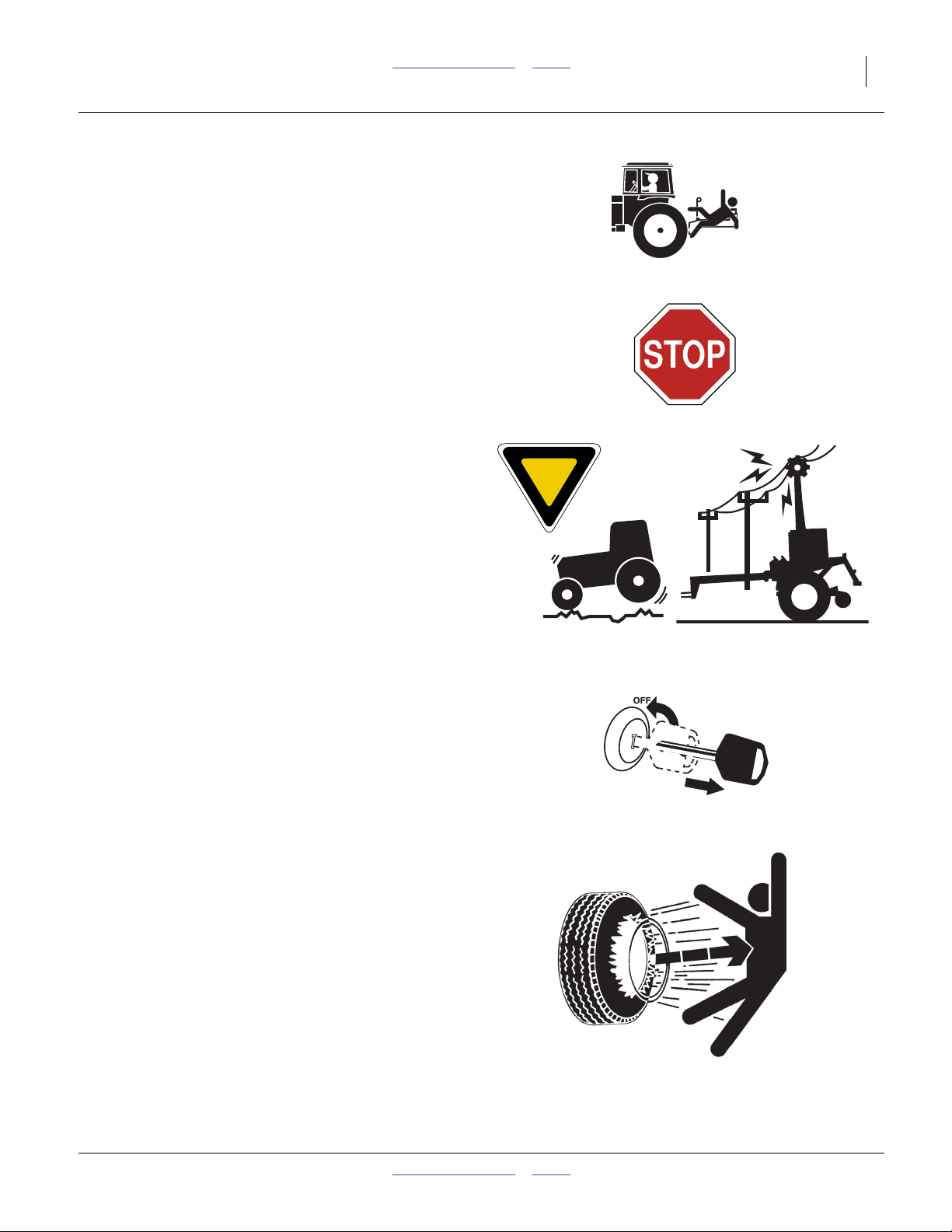
Look for Safety Symbol
The SAFETY ALERT SYMBOL indicates there is a
potential hazard to personal safety involved and extra
safety precaution must be taken. When you see this
symbol, be alert and carefully read the message that follows it. In addition to design and configuration of equipment, hazard control and accident prevention are
dependent upon the awareness, concern, prudence and
proper training of personnel involved in the operation,
transport, maintenance and storage of equipment.
Be Aware of Signal Words
Signal words designate a degree or level of hazard seriousness.
DANGER indicates an imminently hazardous situation
which, if not avoided, will result in death or serious injury.
This signal word is limited to the most extreme situations,
typically for machine components that, for functional purposes, cannot be guarded.
WARNING indicates a potentially hazardous situation
which, if not avoided, could result in death or serious
injury, and includes hazards that are exposed when
guards are removed. It may also be used to alert against
unsafe practices.
CAUTION indicates a potentially hazardous situation
which, if not avoided, may result in minor or moderate
injury. It may also be used to alert against unsafe practices.
Prepare for Emergencies
▲ Be prepared if a fire starts
▲ Keep a first aid kit and fire extinguisher handy.
▲ Keep emergency numbers for doctor, ambulance, hospital
and fire department near phone.
Be Familiar with Safety Decals
▲ Read and understand “Safety Decals” on page 5-8, thor-
oughly.
▲ Read all instructions noted on the decals.
▲ Keep decals clean. Replace damaged, faded and illegible
decals.
06/14/2012 Table of Contents Index 596-086M
Page 6

2 SS1300 & SS1700 Table of Contents Index Great Plains Manufacturing, Inc.
Wear Protective Equipment
▲ Wear protective clothing and equipment.
▲ Wear clothing and equipment appropriate for the job. Avoid
loose-fitting clothing.
▲ Because prolonged exposure to loud noise can cause hear-
ing impairment or hearing loss, wear suitable hearing protection such as earmuffs or earplugs.
▲ Because operating equipment safely requires your full
attention, avoid wearing entertainment headphones while
operating machinery.
Handle Chemicals Properly
Agricultural chemicals can be dangerous. Improper use
can seriously injure persons, animals, plants, soil and
property.
▲ Read and follow chemical manufacturer’s instructions.
▲ Wear protective clothing.
▲ Handle all chemicals with care.
▲ Avoid inhaling smoke from any type of chemical fire.
▲ Store or dispose of unused chemicals as specified by chemi-
cal manufacturer.
Avoid High Pressure Fluids
Escaping fluid under pressure can penetrate the skin,
causing serious injury.
▲ Avoid the hazard by relieving pressure before disconnecting
hydraulic lines.
▲ Use a piece of paper or cardboard, NOT BODY PARTS, to
check for suspected leaks.
▲ Wear protective gloves and safety glasses or goggles when
working with hydraulic systems.
▲ If an accident occurs, seek immediate medical assistance
from a physician familiar with this type of injury.
Use Safety Lights and Devices
Slow-moving tractors and towed implements can create
a hazard when driven on public roads. They are difficult
to see, especially at night.
▲ Use flashing warning lights and turn signals whenever driv-
ing on public roads.
Use lights and devices provided with implement
596-086M Table of Contents Index 06/14/2012
Page 7
Great Plains Manufacturing, Inc. Table of Contents Index Important Safety Information 3
Keep Riders Off Machinery
Riders obstruct the operator’s view. Riders could be
struck by foreign objects or thrown from the machine.
▲ Never allow children to operate equipment.
▲ Keep all bystanders away from machine during operation.
Transport Machinery Safely
Maximum transport speed for implement is 20 mph (32
kph), 13 mph (22 kph) in turns. Some rough terrains
require a slower speed. Sudden braking can cause a
towed load to swerve and upset.
▲ Do not exceed 20 mph. Never travel at a speed which does
not allow adequate control of steering and stopping.
Reduce speed if towed load is not equipped with brakes.
▲ Comply with state and local laws.
▲ Do not tow an implement that, when fully loaded, weighs
more than 1.5 times the weight of towing vehicle.
▲ Carry reflectors or flags to mark Sub-Soiler in case of
breakdown on the road.
▲ Keep clear of overhead power lines and other obstructions
when transporting. Refer to transport dimensions under
“SS1300-SS1700 Specifications and Capacities”on
page 25.
▲ Do not fold or unfold the Sub-Soiler while the tractor is
moving
Shutdown and Storage
▲ Lower Sub-Soiler, put tractor in park, turn off engine, and
remove the key.
▲ Secure Sub-Soiler using blocks and supports provided.
▲ Detach and store machine in an area where children nor-
mally do not play.
Tire Safety
Tire changing can be dangerous and should be performed by trained personnel using correct tools and
equipment.
▲ When inflating tires, use a clip-on chuck and extension hose
long enough for you to stand to one side–not in front of or
over tire assembly. Use a safety cage if available.
▲ When removing and installing wheels, use wheel-handling
equipment adequate for weight involved.
06/14/2012 Table of Contents Index 596-086M
Page 8

4 SS1300 & SS1700 Table of Contents Index Great Plains Manufacturing, Inc.
Practice Safe Maintenance
▲ Understand procedure before doing work. Use proper
tools and equipment. Refer to this manual for additional
information.
▲ Work in a clean, dry area.
▲ Lower the machine, put tractor in park, turn off engine,
and remove key before performing maintenance.
▲ Disconnect battery ground cable (-) before servicing or
adjusting electrical systems or before welding on machine.
▲ Inspect all parts. Make sure parts are in good condition
and installed properly.
▲ Remove buildup of grease, oil or debris.
▲ Remove all tools and unused parts from machine before
operation.
Safety At All Times
Thoroughly read and understand the instructions in this
manual before operation. Read all instructions noted on
the safety decals.
▲ Be familiar with all machine functions.
▲ Operate machinery from the driver’s seat only.
▲ Do not leave Sub-Soiler unattended with tractor engine
running.
▲ Do not stand between the tractor and machine during hitch-
ing.
▲ Keep hands, feet and clothing away from power-driven
parts.
▲ Wear snug-fitting clothing to avoid entanglement with mov-
ing parts.
▲ Watch out for wires, trees, etc., when folding and raising
machine. Make sure all persons are clear of working area.
596-086M Table of Contents Index 06/14/2012
Page 9
Great Plains Manufacturing, Inc. Table of Contents Index Important Safety Information 5
Safety Decals
Safety Reflectors and Decals
Your implement comes equipped with all lights, safety
reflectors and decals in place. They were designed to
help you safely operate your implement.
▲ Read and follow decal directions.
▲ Keep lights in operating condition.
▲ Keep all safety decals clean and legible.
▲ Replace all damaged or missing decals. Order new decals
from your Great Plains dealer. Refer to this section for
proper decal placement.
▲ When ordering new parts or components, also request cor-
responding safety decals.
To install new decals:
1. Clean the area on which the decal is to be placed.
2. Peel backing from decal. Press firmly on surface,
being careful not to cause air bubbles under decal.
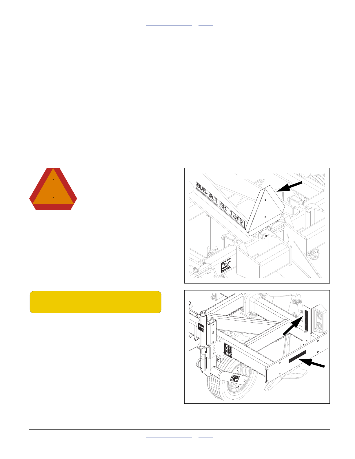
42775
818-055C
Slow Moving Vehicle Reflector
On the back of the center SMV post;
1 total
838-265C
Amber Reflectors
One on front of light bracket and one on center frame
(both sides);
4 total
42777
06/14/2012 Table of Contents Index 596-086M
Page 10
6 SS1300 & SS1700 Table of Contents Index Great Plains Manufacturing, Inc.
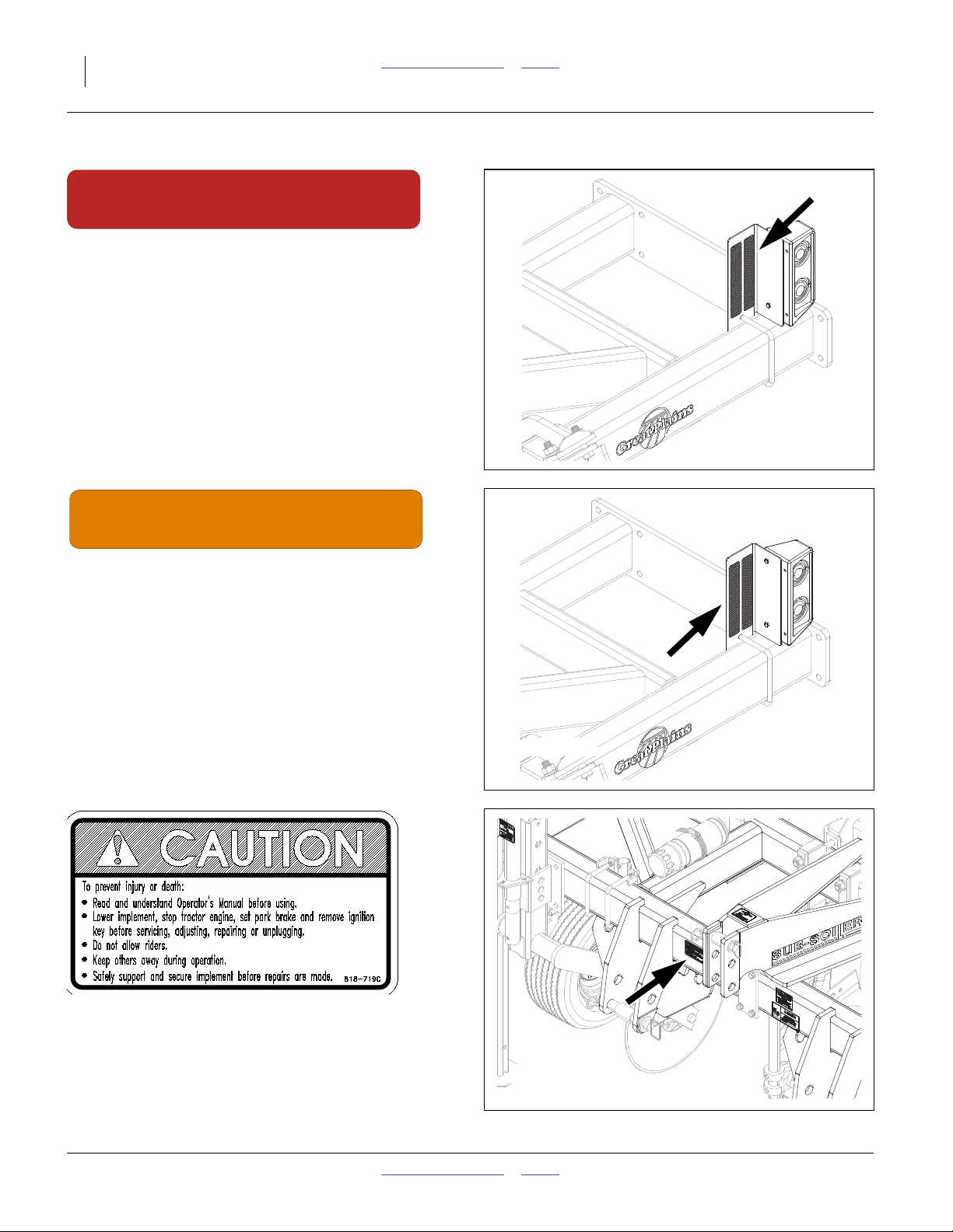
838-266C
Red Reflectors
On rear of light brackets (outside);.
2 total
42776
838-267C
Orange Reflectors
On rear of light brackets (inside);
2 total
818-719C Caution: General Instructions
On front of center frame;
1 total
42776
42778
596-086M Table of Contents Index 06/14/2012
Page 11

Great Plains Manufacturing, Inc. Table of Contents Index Important Safety Information 7
818-337C Warning: Excessive Speed Hazard
On front of center frame;
1 total
42778
818-590C Danger: Crushing Hazard
On front of center frame;
1 total
818-398C Caution: Tires Not A Step
Front side of gauge wheel jacks;
2 total
42778
42777
06/14/2012 Table of Contents Index 596-086M
Page 12
8 SS1300 & SS1700 Table of Contents Index Great Plains Manufacturing, Inc.
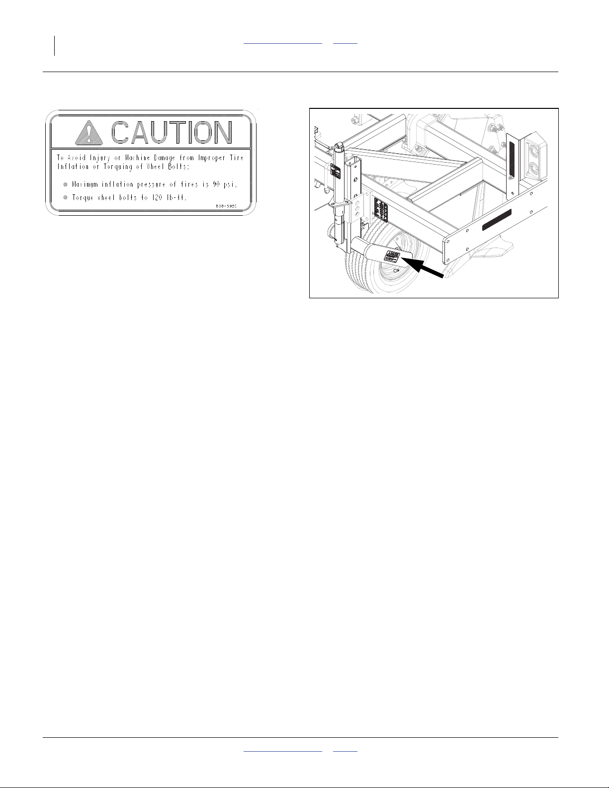
838-595C Caution: Tire 90 PSI
On outside of gauge wheel arms;
2 total
42777
596-086M Table of Contents Index 06/14/2012
Page 13
Great Plains Manufacturing, Inc. Table of Contents Index 9
Introduction
Great Plains welcomes you to our growing family of new
product owners. The Sub-Soiler Inline Ripper SS1300 &
SS1700, 3-8 shank, have been designed with care and
built by skilled workers using quality materials. Proper
setup, maintenance, and safe operating practices will
help you get years of satisfactory use from the machine.
Models Covered
SS1300 30”-centers, 3 shank, 1-section
SS1300 36”-centers, 3 shank, 1-section
SS1300 38”-centers, 3 shank, 1-section
SS1300 40”-centers, 3 shank, 1-section
SS1300 24”-centers, 4 shank, 1-section
SS1300 30”-centers, 4 shank, 1-section
SS1300 36”-centers, 4 shank, 1-section
SS1300 38”-centers, 4 shank, 1-section
SS1300 40”-centers, 4 shank, 1-section
SS1300 30”-centers, 5 shank, 1-section
SS1300 24”-centers, 6 shank, 1-section
SS1300 24”-centers, 8 shank, 1-section
SS1700 36”-centers, 5 shank, 1-section
SS1700 38”-centers, 5 shank, 1-section
SS1700 40”-centers, 5 shank, 1-section
SS1700 30”-centers, 6 shank, 1-section
SS1700 36”-centers, 6 shank, 1-section
SS1700 38”-centers, 6 shank, 1-section
SS1700 40”-centers, 6 shank, 1-section
SS1700 30”-centers, 7 shank, 1-section
SS1700 36”-centers, 7 shank, 1-section
SS1700 38”-centers, 7 shank, 1-section
SS1700 40”-centers, 7 shank, 1-section
SS1700 30”-centers, 8 shank, 1-section
R
L
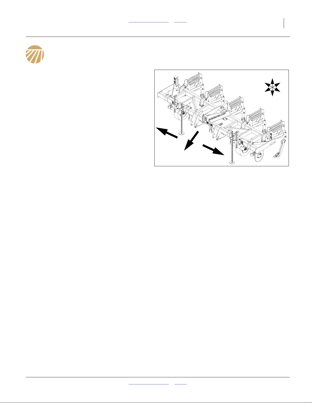
Figure 1
SS1300 Sub-Soiler
R
F
U
B
L
D
21604
See “SS1300-SS1700 Specifications and Capacities”
on page 25 for precise swath information.
06/14/2012 Table of Contents Index 596-086M
Page 14
10 SS1300 & SS1700 Table of Contents Index Great Plains Manufacturing, Inc.
Description of Unit
The Sub-Soiler Inline Ripper SS1300 & SS1700 is a onesection machine. It is designed to break up soil crust on
hard dried fields while eliminating compaction layers. An
optional berm conditioner may be added to the rear of
each shank.
Document Family
596-086M Operator Manual (this document)
596-086P Parts Manual
Using This Manual
This manual will familiarize you with
safety, assembly, operation, adjustments, troubleshooting, and maintenance. Read this manual and follow
the recommendations to help
ensure safe and efficient operation.
Owner Assistance
If you need customer service or repair parts, contact a
Great Plains dealer. They have trained personnel, repair
parts and equipment specially designed for Great Plains
products.
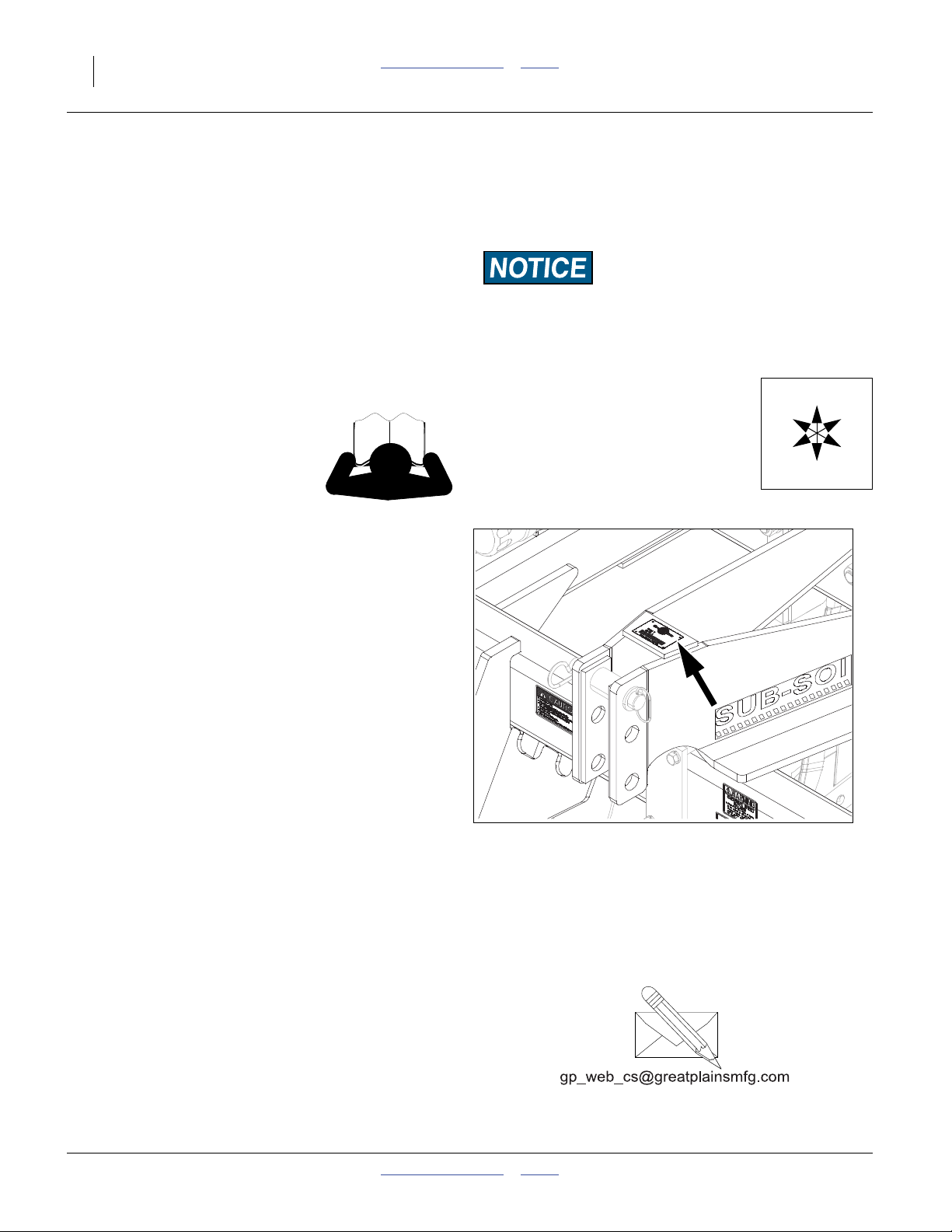
Refer to Figure 2
Your machine’s parts were specially designed and
should only be replaced with Great Plains parts. Always
use the serial and model number when ordering parts
from your Great Plains dealer. The serial-number plate is
located as shown in Figure 2.
Record your SS1300-SS1700 Sub-Soiler model and
serial number here for quick reference:
Model Number:__________________________
Serial Number: __________________________
Your Great Plains dealer wants you to be satisfied with
your new machine. If you do not understand any part of
this manual or are not satisfied with the service received,
please take the following actions.
1. Discuss the matter with your dealership service
manager. Make sure they are aware of any problems
so they can assist you.
If you are still unsatisfied, seek out the owner or general
manager of the dealership.
For further assistance write to:
The information in this manual is current at printing.
Some parts may change to assure top performance.
Definitions
The following terms are used throughout this manual.
A crucial point of information related to the preceding topic.
Read and follow the directions to remain safe, avoid serious
damage to equipment and ensure desired field results.
Note: Useful information related to the preceding topic.
Right-hand and left-hand as used in
this manual are determined by facing
the direction the machine will travel
while in use unless otherwise stated.
An orientation rose in some line art
illustrations shows the directions of:
Up, Back, Left, Down, Front, Right.
Figure 2
Serial Number Plate
Product Support
Great Plains Mfg. Inc., Service Department
PO Box 5060
Salina, KS 67402-5060
R
F
U
B
L
D
42779
(800)255-9215
596-086M Table of Contents Index 06/14/2012
Page 15

Great Plains Manufacturing, Inc. Table of Contents Index 11
Preparation and Setup
This section helps you prepare your tractor and SS1300 &
SS1700 Sub-Soiler for use, and covers tasks that need to
be done seasonally, or when the tractor/Sub-Soiler configuration changes.
Before using the Sub-Soiler in the field, you must hitch it to
a suitable tractor, inspect systems and level the SubSoiler. Before using the Sub-Soiler for the first time, and
periodically thereafter, certain adjustments and calibrations are required.
Prior to Going to the Field Checklist
Complete this checklist before routine setup:
❑ Read and understand “Important Safety Informa-
tion” on page 1.
❑ Check that all working parts are moving freely, bolts
are tight, and cotter pins are spread.
❑ Make sure your tractor horsepower matches the
implement you are pulling. This is important so the
implement can do the best possible job.
❑ Check again for hydraulic leaks and watch that hoses
do not get pinched in hinges, wing stops, etc.
❑ Check that all grease fittings are in place and lubri-
cated. See “Lubrication” on page 23. The hubs will
come pre-greased and will not need greased at this
time.
❑ Check that all safety decals and reflectors are cor-
rectly located and legible. Replace if damaged. See
“Safety Decals” on page 5.
❑ Inflate tires to pressure recommended and tighten
wheel bolts as specified. See “Torque Values Chart”
on page 27.
06/14/2012 Table of Contents Index 596-086M
Page 16

12 SS1300 & SS1700 Table of Contents Index Great Plains Manufacturing, Inc.
Hitching Tractor to Sub-Soiler
Crushing Hazard:
Do not stand or place any part of your body between subsoiler and moving tractor. You may be severely injured or
killed by being crushed between the tractor and sub-soiler.
Stop tractor engine and set parking brake before attaching
cables and hoses.
High Pressure Fluid Hazard:
Relieve pressure before disconnecting hydraulic lines. Use a
piece of paper or cardboard, NOT BODY PARTS, to check for
leaks. Wear protective gloves and safety glasses or goggles
when working with hydraulic systems. Escaping fluid under
pressure can have sufficient pressure to penetrate the skin causing serious injury. If an accident occurs, seek immediate medical assistance from a physician familiar with this type of injury.
Hitching with 3-Point
1. The sub-soiler is designed to use either Category II
or III tractors. This implement is factory set for Category III tractors. To change to Category II, you will
need a Category II Ripper hitch pin kit P/N 596-060A.
See your Great Plains dealer to order kit.
2. In addition, the following bushings (not supplied by
Great Plains) may be needed to fit your quick hitch or
tractor’s 3-point arms:
• Upper Link 1” IDx1 1/4” OD
• Lower Links 1 1/8”IDx1 7/16” OD
3. Be sure that all tractor 3-point arms are securely
pinned before lifting the implement. Adjust the top 3point link so that the frame is at desired tip depth,
parallel with the ground.
4. Set the tractor 3-point draft control in the float position.
5. Raise the tractor 3-point arms as needed and pin
lower arms to implement.
596-086M Table of Contents Index 06/14/2012
Page 17
Great Plains Manufacturing, Inc. Table of Contents Index Preparation and Setup 13
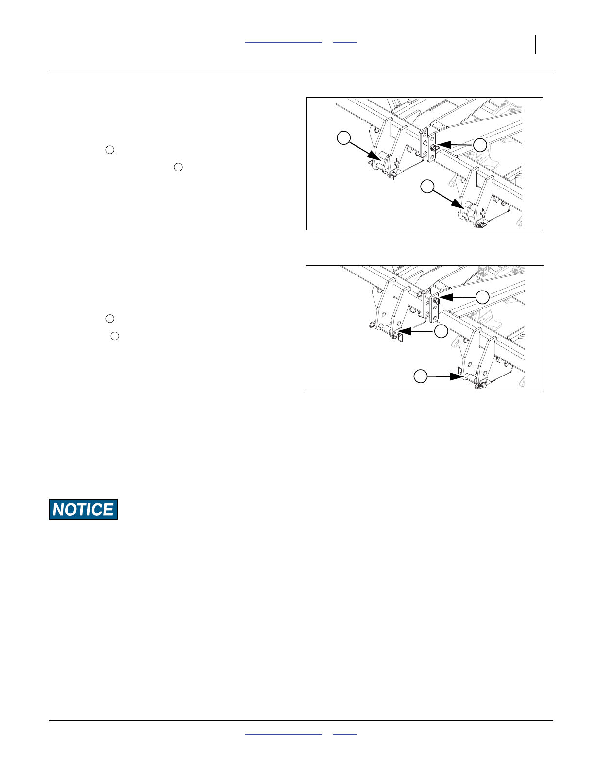
Refer to Figure 3
6. See drawing for correct pins and hole positions for
Category II.
7. Pin upper arm to implement. For category II, install
hitch pin in middle hole.
1
2
1
8. Install hitch pin supports in brackets as shown.
Refer to Figure 4
9. See drawing for correct pins and hole positions for
Category III.
10. Pin upper arm to implement. For category III, install
hitch pin in top hole.
11. Install pin in lower holes.
12. Connect your tractor 3-point to the sub-soiler 3-point
hitch. If using quick hitch be sure sub-soiler locks into
hitch securely.
13. Slowly raise implement. Watch for cab interference.
14. Set your tractor 3-point draft control to float position.
15. Plug lead from implement light harness into tractor
receptacle.
16. Raise tractor 3-point just enough to relieve pressure
from parking stands.
17. Raise and pin up 3-point stands. See “Store Parking
Stands” on page 14.
1
2
2
2
Figure 3
Cat II Hitching
2
2
Figure 4
Cat III Hitching
42780
1
42781
Load Sway Risk:
Adjust 3-point hitch arms and sway blocks to minimize any sideto-side sway to assure proper tracking in the field and safe road
travel.
06/14/2012 Table of Contents Index 596-086M
Page 18
14 SS1300 & SS1700 Table of Contents Index Great Plains Manufacturing, Inc.
Storing Parking Stands
Refer to Figure 5
18. While holding the parking stand , remove the snap
lock pin .
19. Slide the stand clear up in stand mount as shown.
20. Install snap lock pin through aligned holes to secure.
2
1 3
2
1
1
3
2
Shank Mounting
Straight Shanks
21. Attach the straight shank assembly Refer to Figure 6
or no-till shank Refer to Figure 7 to the auto reset
shank mount using 3/4 x 6 Gr. 8 bolts , 3/4” hardened flat washers , two on head side and one on lock
washer side, 3/4” lock washers and 3/4” nuts.
Note: Extra hardened washers allows use of longer bolt to
keep threads out of the shear area.
IMPORTANT: Torque bolts to 400 FT LBS.
2
3 4
5
4
1
Figure 5
Store Parking Stands
41861
1
4
5
5
3
Figure 6
Straight Shank Mounting
42784
2
4
5
5
3
Figure 7
No-Till Mounting
596-086M Table of Contents Index 06/14/2012
42785
Page 19

Great Plains Manufacturing, Inc. Table of Contents Index Preparation and Setup 15
Straight Shins & Tips Assembly
Refer to Figure 8
22. Attach straight shin retainer to the straight shank
with 1/2 x 2 1/2 bolts , 1/2 hardened washer and 1/
2 flange lock nut.
23. Slide one end of the straight wear shin under the
straight shin retainer . Hold the lower end in place by
installing a tip (1 1/4 x 2 with fin, shown) . Fasten with
1/2 x 2 1/2 bolts , 1/2 hardened washer and 1/2
flange lock nut.
Note: Install the 1/2 x 2 1/2 bolts as shown. The flow of
dirt on the underside of tip will tend to tighten nut.
3 4
1
3 4
1 2
5
6
3
1
4
3
5
2
4
6
3
No-Till Shins & Tips Assembly
Refer to Figure 9
24. Attach the retainer clip to the no-till shank with 1/2
x 1 3/4 bolts and 1/2 flange lock nut.
25. Remove the 1/2 x 1 3/4 roll pin and save for later
use.
26. Slide one end of the no-till wear shin under the
retainer clip . Hold the lower end in place by installing
a no-till tip . Secure with 1/2 x 1 3/4 roll pin in rear
hole of tip (removed in previous step).
27. Insert the 3/4 x 1.7 heavy roll pin in front hole of tip
6
to help secure tip.
3
1
6 4
1 2
4
5
7
Coulter Assembly
Refer to Figure 10
28. Position the coulter stop in the slot of the casting
assembly .
29. Slide the casting assembly and coulter stop onto shank
3
, sliding it up past the hole in the end.
30. Install roll pin in the hole and allow casting to slide
back down until it is resting on the roll pin.
31. Place jam nut on 5/8x1 1/2” set screw and insert
set screw in the casting assembly. Insert 5/8x1 set
screw in the coulter stop and refer to See “Coulter
Alignment” on page 17 for proper setting.
2
4
6 5
7
1
Figure 8
Straight Shins & Tips
1
5
6
Figure 9
No-Till Shins & Tips
3
4
6
5
1
7
Figure 10
Coulters
42786
2
3
4
7
42787
2
5
42790
06/14/2012 Table of Contents Index 596-086M
Page 20

16 SS1300 & SS1700 Table of Contents Index Great Plains Manufacturing, Inc.
Machine Adjustments
Pre-Leveling of Machine
Front to Rear Leveling
32. Pre-leveling of machine may be done on a level floor.
Lower the machine down until the shank tips are just
above the floor.
33. Adjust the 3 point top link until the front and rear points
are level.
Auto Reset Shank Adjustment
Refer to Figure 11
34. The dual spring package should be preloaded so both
top and bottom springs are loaded evenly and measure
23.8” from end of coil to end of coil.
Spring pack is pre-loaded at factory and should not be disassembled in the field. You could be severely injured or killed by instant
release of stored energy.
Figure 11
Auto Reset Shanks
Down Stop
(not visible)
24464
596-086M Table of Contents Index 06/14/2012
Page 21

Great Plains Manufacturing, Inc. Table of Contents Index Preparation and Setup 17
Gauge Wheel Adjustment
Refer to Figure 12
Note: The jacks should only be used to help raise and lower
the guage wheels . The cross pin still needs to be
used in order to avoid overloading the jack.
35. Adjust the gauge wheel as shown on the shank depth
2
decal on the front of the frame.
1
Cross Pin
2
1
Coulter Adjustment
Refer to Figure 13
Coulter Height
36. Determine the desired depth of the shank and set the
gauge wheel in the appropriate hole.
37. Subtract 8” from the shank depth. Take this distance
and measure from the top of the frame to the top of
the coulter shank . This will allow the coulter to run
approximately hub deep. If trying to deep rip less than
8”, position the top of the coulter shank flush with the
top of the tube.
2
Coulter Alignment
Refer to Figure 13
38. Loosen the top and bottom set screws , jam nuts
and swivel limiter set screw . Lower the ripper in the
ground and drive forward a few feet.
39. Leave the ripper in the ground and tighten the top and
bottom set screws and jam nuts . Position the
swivel limiter in the center of the slot and tighten the
set screw .
40. Check alignment of the coulter and shank. Move either
the coulter or shank so the shank is in the center of the
grove made by the coulter.
Note: Note: If you want the coulter to swivel, loosen the top
and bottom set screws and jam nuts . Retighten
jam nut to prevent from loosing set screw.
5
3 4
5
1 2
1
3 4
Figure 12
Gauge Wheels
4
3
5
3
Figure 13
Coulter Alignment
42783
838-597C
2
1
42791
06/14/2012 Table of Contents Index 596-086M
Page 22

18 SS1300 & SS1700 Table of Contents Index Great Plains Manufacturing, Inc.
Coulter Spring
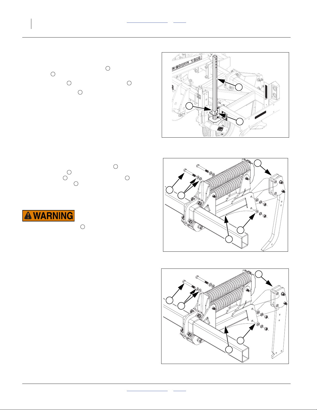
Refer to Figure 14
41. The coulter springs are preset at the factory to
between 9 7/8” to 10”. This is measured from the inside
surface of the coulter spring washer to the inside surface of the coulter bushing.
Note: Adjusting the spring below 9 7/8” could cause prema-
ture part failure and void the warranty.
Berm Conditioner
Refer to Figure 15
42. The berm conditioner may be adjusted pulling up on
handle sliding to a different notch.
43. For the deepest setting, move handle clear forward.
For shallower, move handle towards rear.
Figure 14
Coulter Spring Adjustment
Figure 15
Berm Conditioner Adjustment
42792
41864
596-086M Table of Contents Index 06/14/2012
Page 23

Great Plains Manufacturing, Inc. Table of Contents Index 19
Operating Instructions
This section covers general operating procedures. Experience, machine familiarity, and the following information
will lead to efficient operation and good working habits.
Always operate farm machinery with safety in mind.
Pre-Start Checklist
Perform the following steps before transporting the
SS1300-SS1700 Sub-Soiler to the field.
❑ Carefully read “Important Safety Information” on
page 1.
❑ Lubricate Sub-Soiler as indicated under “Lubrica-
tion” on page 23.
❑ Check all tires for proper inflation. “Tire Inflation
Chart” on page 26
❑ Check all bolts, pins, and fasteners. Torque as
shown in “Torque Values Chart” on page 27.
❑ Check Sub-Soiler for worn or damaged parts. Repair
or replace parts before going to the field.
High Pressure Fluid Hazard:
Relieve pressure and shut down tractor before connecting, disconnecting or checking hydraulic lines. Use a piece of paper
or cardboard, NOT BODY PARTS, to check for leaks. Wear
protective gloves and safety glasses or goggles when working
with hydraulic systems. Escaping fluid under pressure can
have sufficient pressure to penetrate the skin causing serious
injury. If an accident occurs, seek immediate medical assistance from a physician familiar with this type of injury.
Field Operation
You may be severely injured or killed by being crushed
between the tractor and implement. Do not stand or place any
part of your body between implement and moving tractor. Stop
tractor engine and set park brake before installing pins.
44. Hitch implement to a suitable tractor, See “Hitching
Tractor to Sub-Soiler” on page 12-33.
45. Check to be sure machine is running level from front
to rear when running machine at depth desired. See
“Front to Rear Leveling” on page 16
46. Adjust guage wheels to desired tillage depth. See
“Gauge Wheel Adjustment” on page 17.
47. Adjust and align coulters to desired tillage depth.
“Coulter Alignment” on page 17
48. Always lift implement out of the ground when turning
at field ends and for other short-radius turns.
49. Both the Auto reset and Rigid shank mounts are protected by shear bolts for extreme overloads. If the
shank bolt shears replace the lower bolt with the correct shear bolt, use GP part number 802-060C.
(HHCS 5/8-11 x 4 Gr5).
06/14/2012 Table of Contents Index 596-086M
Page 24

20 SS1300 & SS1700 Table of Contents Index Great Plains Manufacturing, Inc.
Transporting
See “Hitching Tractor to Sub-Soiler” on page 12-13
before transporting the Sub-Soiler.
Check Tractor Capacity and Configuration
• Consult your tractor manual for 3-point limitations.
• Add weights to tractor as required.
When determining the weight of your Sub-Soiler, be sure
to include the weight of any options.
Transport Checklist
❑ Plan the route. Avoid steep hills. Keep Clearances in
mind.
❑ Make all electrical connections, See “Hitching Trac-
tor to Sub-Soiler” on page 12-13.
❑ Raise Sub-Soiler.
❑ Always have lights on for highway operation.
❑ Comply with all federal, state and local safety laws
when traveling on public roads.
❑ Travel with caution. Allow safe clearance.
Remember that the Sub-Soiler is wider than the tractor.
Loss of Control Hazard:
Use a tractor rated for the load. Add tractor ballast as needed.
Do not exceed 20 mph. Towing the Sub-Soiler with a vehicle
that is not adequate, or at high speeds, could lead to loss of
vehicle control. Loss of vehicle can result in a serious road
accident, severe injury or death. Check that your tractor has
enough to handle the weight of the Sub-Soiler. Refer to your
tractor’s operator manual for capacities and ballast requirements.
Parking
Perform the following steps when parking the implement.
Refer to “Storage”, page 22, to prepare for long-term storage.
50. Park implement on a level, solid area.
51. Lower implement until shanks are resting on the
ground.
Refer to Figure 16
52. Lower and pin parking stands.
53. Unplug light harness lead from tractor receptacle. Do
not allow lead to rest on the ground.
54. Unhitch from the tractor 3-point.
Figure 16
Parking Stands
21604
596-086M Table of Contents Index 06/14/2012
Page 25

Great Plains Manufacturing, Inc. Table of Contents Index 21
Troubleshooting
Problem Cause Solution
Excessive blowout
Going too fast. Slow down.
Ripping too shallow. Raise guage wheel.
Coulter not deep enough. Lower coulter, see “Coulter
Shank not aligned with coulter. Align shank with trench made by
Height”,
coulter, see “Coulter Alignment”,
page 18.
page 17.
06/14/2012 Table of Contents Index 596-086M
Page 26

22 SS1300 & SS1700 Table of Contents Index Great Plains Manufacturing, Inc.
Maintenance and Lubrication
Maintenance
55. Proper servicing and maintenance is the key to long
implement life. With careful and systematic inspection,
you can avoid costly maintenance, downtime and
repair.
56. Always turn off and remove the tractor key before making any adjustments or performing any maintenance
Refer to Figure 17
57. After using the implement for several hours, check all
bolts to be sure they are tight.
58. After one hour and again after five hours re-torque the
Gr. 8 bolts and Gr. 8 clamp bolts to 400 FT LBS.
Re-torque periodically.
59. Lubricate areas listed under “Lubrication”, page 23.
60. Inflate tires as specified on “Tire Inflation Chart”, page
27.
61. Replace or rotate worn parts as needed -- hinge bolts,
clevis pins, bearings, etc.
62. Check and tighten or replace any hydraulic leaks. Check
hoses for any leaks. It is important that there are no
leaks on the equipment.
63. Grease wheel bearings and walking beams sparingly.
Over greasing may cause damage to seals and reduce
the life of the bearing. Grease hinge points periodically.
1 2
2
Figure 17
Re-torque Bolts
1
42793
Storage
64. Store implement where children do not play. If possible, store the implement inside for longer life.
65. Remove any dirt and debris that can hold moisture
and cause corrosion.
66. Lubricate areas noted under “Lubrication”, page 23.
67. Inspect implement for worn or damaged parts. Make
repairs and service during the off season.
68. Use spray paint to cover scratches, chips and worn
areas on the implement to protect the metal.
By following and maintaining a routine service and lubrication program, your tillage equipment will give you
many years of service.
For the most current manual information, visit Great
Plains website listed below. For more information on
operating, adjusting or maintaining your Great
Plains Discovator, assistance is available. Contact:
Product Support
Great Plains Mfg. Inc., Service Department
PO Box 5060
Salina, KS 67402-5060
(800)255-9215
596-086M Table of Contents Index 06/14/2012
Page 27

Great Plains Manufacturing, Inc. Table of Contents Index Maintenance and Lubrication 23
Lubrication
Multipurpose
spray lube
Multipurpose
grease lube
Shank Pivot Arms
8
1 zerk on each shank pivot arm.;
Type of Lubrication: Grease
Quantity: Until grease emerges.
Wheel Bearings
Seasonally
One on each guage wheel.
Type of Lubrication: Grease
Quantity: Pump grease into bearings until resistance is
felt, being careful not to pressurize seal or blow out cap.
Multipurpose
oil lube
41730
Intervals (service hours)
at which lubrication is
50
required
41618
Coulter Swing Arms
8
1 zerk on each hub;
Type of Lubrication: Grease
Quantity: Until grease emerges.
Coulter Hubs
Seasonally
1 zerk on each hub;
Type of Lubrication: Grease
Quantity: Pump grease until resistance is felt, being careful not pressurize seal or blow out cap.
41672
41672
06/14/2012 Table of Contents Index 596-086M
Page 28

24 SS1300 & SS1700 Table of Contents Index Great Plains Manufacturing, Inc.
Berm Conditioner (Optional)
Twice a
Season
2 zerk on each basket;
Type of Lubrication: Grease
Quantity: Sparingly, Do Not Over Grease.
41864
596-086M Table of Contents Index 06/14/2012
Page 29

Great Plains Manufacturing, Inc. Table of Contents Index 25
Appendix
SS1300-SS1700 Specifications and Capacities
Model SS1300
Shank Spacing 76cm (30") 91cm (36") 97cm (38") 102cm (40") 61cm (24") 76cm (30")
Number of Shanks 333344
Weight (Rigid No-Till Shank) 1061kg (2339lbs) 1061kg (2339lbs) 1061kg (2339lbs) 1061kg (2339lbs) 1143kg (2519lbs) 1143kg (2519lbs)
Weight (Auto ResetShank)
Working Width 229cm (7' 6") 274cm (9' 0") 290cm (9' 6") 305cm (10' 0") 244cm (8' 0") 244cm (8' 0")
Transport Width 340cm (11' 2") 340cm (11' 2") 340cm (11' 2") 340cm (11' 2") 340cm (11' 2") 340cm (11' 2")
Gauge Wheel Tire Size 20.5X8 10 PLY 20.5X8 10 PLY 20.5X8 10 PLY 20.5X8 10 PLY 20.5X8 10 PLY 20.5X8 10 PLY
Number of Gauge Wheels 222222
Horsepower (PTO) 150-240 150-240 150-240 150-240 200-320 200-320
Kilowatt 112-179 112-179 112-179 112-179 150-239 150-239
Model SS1300
Shank Spacing 91cm (36") 97cm (38") 102cm (40") 76cm (30") 61cm (24") 61cm (24")
Number of Shanks 444568
Weight (Rigid No-Till Shank) 1143kg (2519lbs) 1143kg (2519lbs) 1143kg (2519lbs) 1220kg (2688lbs) 1403kg (3092lbs) 1714kg (3778lbs)
Weight (Auto ResetShank)
Working Width 366cm (12' 0") 386cm (12' 7") 338cm (11' 0") 305cm (10' 0") 366cm (12' 0") 488cm (16' 0")
Transport Width 340cm (11' 2") 340cm (11' 2") 340cm (11' 2") 340cm (11' 2") 340cm (11' 2") 399cm (13' 0")
Gauge Wheel Tire Size 20.5X8 10 PLY 20.5X8 10 PLY 20.5X8 10 PLY 20.5X8 10 PLY 20.5X8 10 PLY 20.5X8 10 PLY
Number of Gauge Wheels 222222
Horsepower (PTO) 200-320 200-320 200-320 250-400 300-480 400+
Kilowatt 150-239 150-239 150-239 187-299 224--358 298+
1424kg (3140lbs) 1424kg (3140lbs) 1424kg (3140lbs) 1424kg (3140lbs) 1627kg (3587lbs) 1627kg (3587lbs)
1627kg (3587lbs) 1627kg (3587lbs) 1627kg (3587lbs) 1825kg (4023lbs) 2129kg (4694lbs) 2683kg (5914lbs)
Model SS1700
Shank Spacing 91cm (36") 97cm (38") 102cm (40") 76cm (30") 91cm (36") 97cm (38")
Number of Shanks 555666
Weight (Rigid No-Till Shank) 1327kg (2925lbs) 1327kg (2925lbs) 1327kg (2925lbs) 1406kg (3100lbs) 1406kg (3100lbs) 1406kg (3100lbs)
Weight (Auto ResetShank)
Working Width 457cm (15' 0") 483cm (15' 9") 508 (16' 7") 457cm (15' 0") 549cm (18' 0") 579cm (19' 0")
Transport Width 443cm (14' 5") 549cm (18' 0") 508 (16' 7") 448cm (14' 7") 547cm (17' 9") 549cm (18' 0")
Gauge Wheel Tire Size 20.5X8 10 PLY 20.5X8 10 PLY 20.5X8 10 PLY 20.5X8 10 PLY 20.5X8 10 PLY 20.5X8 10 PLY
Number of Gauge Wheels 222222
Horsepower (PTO) 250-400 250-400 250-400 300-480 300-480 300-480
Kilowatt 187-299 187-299 187-299 224--358 224--358 224--358
Model SS1700
Shank Spacing 102cm (40") 76cm (30") 91cm (36") 97cm (38") 102cm (40") 76cm (30")
Number of Shanks 677778
Weight (Rigid No-Till Shank) 1406kg (3100lbs) 1627kg (3588lbs) 1627kg (3588lbs) 1627kg (3588lbs) 1627kg (3588lbs) 1743kg (3842lbs)
Weight (Auto ResetShank)
Working Width 610cm (20' 0") 533cm (17' 6") 640 (21' 0") 676cm (22' 2") 711cm (23' 4") 610cm (20' 0")
Transport Width 598cm (19' 6") 547cm (17' 9") 591 (19' 4") 648cm (21' 4") 645cm (21' 2") 600cm (19' 7")
Gauge Wheel Tire Size 20.5X8 10 PLY 20.5X8 10 PLY 20.5X8 10 PLY 20.5X8 10 PLY 20.5X8 10 PLY 20.5X8 10 PLY
Number of Gauge Wheels 222222
Horsepower (PTO) 300-480 350+ 350+ 350+ 350+ 400+
Kilowatt 224--358 261+ 261+ 261+ 261+ 298+
1932kg (4260lbs) 1932kg (4260lbs) 1932kg (4260lbs) 2133kg (4702lbs) 2133kg (4702lbs) 2133kg (4702lbs)
2133kg (4702lbs) 2420kg (5336lbs) 2420kg (5336lbs) 2420kg (5336lbs) 2420kg (5336lbs) 2712kg (5979lbs)
06/14/2012 Table of Contents Index 596-086M
Page 30

26 SS1300 & SS1700 Table of Contents Index Great Plains Manufacturing, Inc.
Tire Inflation Chart
Tire Inflation Chart
Tire Inflation Chart
Wheel Tire Size Inflation
Gauge
Wheel
20.5x8.0 10-ply
LRE
90 psi
621 kPa
Tire Warranty Information
All tires are warranted by the original manufacturer of the tire.
Tire warranty information is found in the brochures included with
your Operator’s and Parts Manuals or online at the manufacturer’s web sites listed below. For assistance or information, contact your nearest Authorized Farm Tire Retailer.
Manufacturer Web site
Firestone www.firestoneag.com
Gleason www.gleasonwheel.com
Titan www.titan-intl.com
Galaxy www.atgtire.com
BKT www.bkt-tire.com
596-086M Table of Contents Index 06/14/2012
Page 31

Great Plains Manufacturing, Inc. Table of Contents Index Appendix 27
Torque Values Chart
Bolt
Size
in-tpi
1
⁄4-20
1
⁄4-28
5
⁄16-18
5
⁄16-24
3
⁄8-16
3
⁄8-24
7
⁄16-14
7
⁄16-20
1
⁄2-13
1
⁄2-20
9
⁄16-12
9
⁄16-18
5
⁄8-11
5
⁄8-18
3
⁄4-10
3
⁄4-16
7
⁄8-9
7
⁄8-14
1-8
1-12
1
1
⁄8-7
1
⁄8-12
1
1
⁄4-7
1
1
1
⁄4-12
3
⁄8-6
1
3
1
⁄8-12
1
1
⁄2-6
1
1
⁄2-12
Bolt Head Identification
Grade 2 Grade 5 Grade 8 Class 5.8 Class 8.8 Class 10.9
a
b
d
N-m
ft-lb
7.4 11 16
8.5 13 18
15 24 33
17 26 37
27 42 59
31 47 67
43 67 95
49 75 105
66 105 145
75 115 165
95 150 210
105 165 235
130 205 285
150 230 325
235 360 510
260 405 570
225 585 820
250 640 905
340 875 1230
370 955 1350
480 1080 1750
540 1210 1960
680 1520 2460
750 1680 2730
890 1990 3230
1010 2270 3680
1180 2640 4290
1330 2970 4820
N-m N-m
5.6 8 12
61014 5 811
11 17 25 12 19 27
13 19 27 13 21 29
20 31 44 24 39 53
22 35 49 29 45 62
32 49 70 42 67 93
36 55 78 44 70 97
49 76 105 66 77 105
55 85 120 68 105 150
70 110 155 73 115 160
79 120 170 105 165 230
97 150 210 115 180 245
110 170 240 145 230 300
170 265 375 165 260 355
190 295 420 205 325 450
165 430 605 230 480 665
185 475 670 355 560 780
250 645 910 390 610 845
275 705 995 705 1120 1550
355 795 1290 785 1240 1710
395 890 1440 1270 1950 2700
500 1120 1820 1380 2190 3220
555 1240 2010
655 1470 2380
745 1670 2710
870 1950 3160
980 2190 3560
Bolt Head Identification
Bolt
Size
ft-lb ft-lb ft-lb ft-lb ft-lb
mm x pitch
M 5 X 0.8
M 6 X 1
M 8 X 1.25
M 8 X 1
M10 X 1.5
M10 X 0.75
M12 X 1.75
M12 X 1.5
M12 X 1
M14 X 2
M14 X 1.5
M16 X 2
M16 X 1.5
M18 X 2.5
M18 X 1.5
M20 X 2.5
M20 X 1.5
M24 X 3
M24 X 2
M30 X 3.5
M30 X 2
M36 X 3.5
M36 X 2
a. in-tpi = nominal thread diameter in inches-threads per inch
b. N· m = newton-meters
c. mm x pitch = nominal thread diameter in mm x thread pitch
d. ft-lb = foot pounds
5.8 8.8 10.9
c
N-m N-m N-m
357
71115
17 26 36
18 28 39
33 52 72
39 61 85
58 91 125
60 95 130
90 105 145
92 145 200
99 155 215
145 225 315
155 240 335
195 310 405
220 350 485
280 440 610
310 650 900
480 760 1050
525 830 1150
960 1510 2100
1060 1680 2320
1730 2650 3660
1880 2960 4100
946
Torque tolerance + 0%, -15% of torquing values. Unless otherwise specified use torque values listed above.
25199m
25199
Wheel Bolt Torque Values 1/2”-20 (75-85 ft-lbs) 9/16”-18 (80-90 ft-lbs) 5/8”-18 (85-100 ft-lbs)
06/14/2012 Table of Contents Index 596-086M
Page 32

28 SS1300 & SS1700 Table of Contents Index Great Plains Manufacturing, Inc.
SS1300-03-30” Machine Layout
42746
596-086M Table of Contents Index 06/14/2012
Page 33

Great Plains Manufacturing, Inc. Table of Contents Index Appendix 29
SS1300-03-36” Machine Layout
42747
06/14/2012 Table of Contents Index 596-086M
Page 34

30 SS1300 & SS1700 Table of Contents Index Great Plains Manufacturing, Inc.
SS1300-03-38” Machine Layout
42748
596-086M Table of Contents Index 06/14/2012
Page 35

Great Plains Manufacturing, Inc. Table of Contents Index Appendix 31
SS1300-03-40” Machine Layout
42749
06/14/2012 Table of Contents Index 596-086M
Page 36

32 SS1300 & SS1700 Table of Contents Index Great Plains Manufacturing, Inc.
SS1300-04-24” Machine Layout
42750
596-086M Table of Contents Index 06/14/2012
Page 37

Great Plains Manufacturing, Inc. Table of Contents Index Appendix 33
SS1300-04-30” Machine Layout
42751
06/14/2012 Table of Contents Index 596-086M
Page 38

34 SS1300 & SS1700 Table of Contents Index Great Plains Manufacturing, Inc.
SS1300-04-36” Machine Layout
42752
596-086M Table of Contents Index 06/14/2012
Page 39

Great Plains Manufacturing, Inc. Table of Contents Index Appendix 35
SS1300-04-38” Machine Layout
42753
06/14/2012 Table of Contents Index 596-086M
Page 40

36 SS1300 & SS1700 Table of Contents Index Great Plains Manufacturing, Inc.
SS1300-04-40” Machine Layout
42754
596-086M Table of Contents Index 06/14/2012
Page 41

Great Plains Manufacturing, Inc. Table of Contents Index Appendix 37
SS1300-05-30” Machine Layout
42755
06/14/2012 Table of Contents Index 596-086M
Page 42

38 SS1300 & SS1700 Table of Contents Index Great Plains Manufacturing, Inc.
SS1300-06-24” Machine Layout
42756
596-086M Table of Contents Index 06/14/2012
Page 43

Great Plains Manufacturing, Inc. Table of Contents Index Appendix 39
SS1300-08-24”Machine Layout
42757
06/14/2012 Table of Contents Index 596-086M
Page 44

40 SS1300 & SS1700 Table of Contents Index Great Plains Manufacturing, Inc.
SS1700-05-36” Machine Layout
42758
596-086M Table of Contents Index 06/14/2012
Page 45

Great Plains Manufacturing, Inc. Table of Contents Index Appendix 41
SS1700-05-38” Machine Layout
42759
06/14/2012 Table of Contents Index 596-086M
Page 46

42 SS1300 & SS1700 Table of Contents Index Great Plains Manufacturing, Inc.
SS1700-05-40” Machine Layout
42760
596-086M Table of Contents Index 06/14/2012
Page 47

Great Plains Manufacturing, Inc. Table of Contents Index Appendix 43
SS1700-06-30” Machine Layout
42761
06/14/2012 Table of Contents Index 596-086M
Page 48

44 SS1300 & SS1700 Table of Contents Index Great Plains Manufacturing, Inc.
SS1700-06-36” Machine Layout
42762
596-086M Table of Contents Index 06/14/2012
Page 49

Great Plains Manufacturing, Inc. Table of Contents Index Appendix 45
SS1700-06-38” Machine Layout
42763
06/14/2012 Table of Contents Index 596-086M
Page 50

46 SS1300 & SS1700 Table of Contents Index Great Plains Manufacturing, Inc.
SS1700-06-40” Machine Layout
42764
596-086M Table of Contents Index 06/14/2012
Page 51

Great Plains Manufacturing, Inc. Table of Contents Index Appendix 47
SS1700-07-30” Machine Layout
42765
06/14/2012 Table of Contents Index 596-086M
Page 52

48 SS1300 & SS1700 Table of Contents Index Great Plains Manufacturing, Inc.
SS1700-07-36” Machine Layout
42766
596-086M Table of Contents Index 06/14/2012
Page 53

Great Plains Manufacturing, Inc. Table of Contents Index Appendix 49
SS1700-07-38” Machine Layout
42767
06/14/2012 Table of Contents Index 596-086M
Page 54

50 SS1300 & SS1700 Table of Contents Index Great Plains Manufacturing, Inc.
SS1700-07-40” Machine Layout
42768
596-086M Table of Contents Index 06/14/2012
Page 55

Great Plains Manufacturing, Inc. Table of Contents Index Appendix 51
SS1700-08-30” Machine Layout
42769
06/14/2012 Table of Contents Index 596-086M
Page 56

52 SS1300 & SS1700 Table of Contents Index Great Plains Manufacturing, Inc.
Warranty
Great Plains Manufacturing, Incorporated warrants to the original purchaser that this tillage
and workmanship for a period of one year from the date of original purchase when used as intended and under normal service and conditions
for personal use; 90 days for commercial or rental purposes. This Warranty is limited to the replacement of any defective part by Great Plains
Manufacturing, Incorporated and the installation by the dealer of any
such replacement part. Great Plains reserves the right to inspect any
equipment or part which are claimed to have been defective in material
or workmanship.
This Warranty does not apply to any part or product which in Great
Plains’ judgement shall have been misused or damaged by accident or
lack of normal maintenance or care, or which has been repaired or altered in a way which adversely affects its performance or reliability, or
which has been used for a purpose for which the product is not designed. This Warranty shall not apply if the product is towed at a speed
in excess of 20 miles per hour.
Claims under this Warranty must be made to the dealer which originally
sold the product and all warranty adjustments must by made through
such dealer. Great Plains reserves the right to make changes in materials or design of the product at any time without notice.
This Warranty shall not be interpreted to render Great Plains liable for
damages of any kind, direct, consequential, or contingent, to property.
Furthermore, Great Plains shall not be liable for damages resulting from
any cause beyond its reasonable control. This Warranty does not extend to loss of crops, losses caused by harvest delays or any expense
or loss for labor, supplies, rental machinery or for any other reason.
No other warranty of any kind whatsoever, express or implied, is
made with respect to this sale; and all implied warranties of merchantability and fitness for a particular purpose which exceed
the obligations set forth in this written warranty are hereby disclaimed and excluded from this sale.
This Warranty is not valid unless registered with Great Plains Manufacturing, Incorporated within 10 days from the date of original purchase.
equipment will be free from defects in material
42134
596-086M Table of Contents Index 06/14/2012
Page 57

Great Plains Manufacturing, Inc. Table of Contents 53
Index
A
address, Great Plains ............. 10, 22
amber reflectors ................................. 5
Auto Reset Shanks .......................... 16
B
bearings ........................................... 22
berm conditioner adjustment ........... 18
berm conditoner ............................... 24
C
Caution
Read Operator’s Manual .............. 6
CAUTION, defined ............................. 1
checklists
pre-setup .................................... 11
pre-start ...................................... 19
transport ..................................... 20
chemicals ........................................... 2
children .............................................. 3
clothing ............................................... 2
contact Great Plains ................ 10
Coulter Alignment ............................ 17
Coulter Hubs .................................... 23
coulter swing arms ........................... 23
covered models .................................. 9
customer service .............................. 10
, 22
D
Danger
Crushing Hazard .......................... 7
DANGER, defined .............................. 1
decal replacement .............................. 5
decals
caution
general instructions ................ 6
tire 90 psi ................................ 8
tires not a step ........................ 7
danger
crushing hazard ...................... 7
speed
30km per hr ............................ 8
warning
excessive speed hazard ......... 7
decal, safety ....................................... 5
definitions ......................................... 10
directions .......................................... 10
E
email, Great Plains .................. 10, 22
F
field operation .................................. 19
fire ...................................................... 1
G
Guage Wheels ................................. 17
H
headphones ....................................... 2
hearing ............................................... 2
high pressure fluids ............................ 2
hitching ............................................ 12
category II .................................. 13
category III ................................. 13
hydraulic safety .................................. 2
Hydraulics
Parking ....................................... 20
I
inflation ............................................ 26
K
kPa ................................................... 26
L
layout
SS1300-03-30
machine ................................ 28
SS1300-03-36
machine ................................ 29
SS1300-03-38
machine ................................ 30
SS1300-03-40
machine ................................ 31
SS1300-04-24
machine ................................ 32
SS1300-04-30
machine ................................ 33
SS1300-04-36
machine ................................ 34
SS1300-04-38
machine ................................ 35
SS1300-05-30
machine ................................ 37
SS1300-06-24
machine ................................ 38
SS1300-08-24
machine ................................ 39
SS1700-03-36
machine ................................ 40
SS1700-05-38
machine ................................ 41
SS1700-05-40
machine ................................ 42
SS1700-06-30
machine ................................ 43
SS1700-06-36
machine ................................ 44
SS1700-06-38
machine ................................ 45
SS1700-06-40
machine ................................ 46
SS1700-07-30
machine ................................ 47
SS1700-07-36
machine ................................ 48
SS1700-07-38
machine ................................ 49
SS1700-07-40
machine ................................ 50
SS1700-08-30
machine ................................ 51
SS2000-07-40
machine ................................ 36
leaks .......................................... 2
left-hand, defined .............................10
lights ................................................... 2
lubrication ......................................... 23
, 22
M
Maintenance .....................................22
maintenance safety ............................4
medical assistance ........... 2
model number ..................................10
, 12, 19
06/14/2012 Table of Contents 596-086M
Page 58

54 SS1300 & SS1700 Table of Contents Index Great Plains Manufacturing, Inc.
N
Note, defined ................................... 10
Notice, defined ................................. 10
O
orange reflector .................................. 6
orientation rose ................................ 10
owner assistance ............................. 10
P
Parking Stands ................................. 20
parking stands
storage ....................................... 14
parts ................................................. 22
phone number, GP ........................... 11
pin, parking stand ............................ 14
Pre-leveling of machine ................... 16
protective equipment .......................... 2
psi .................................................... 26
R
red reflectors ...................................... 6
reflectors
amber ........................................... 5
orange .......................................... 6
red ................................................ 6
SMV ............................................. 5
reflectors, safety ................................. 5
repair parts ....................................... 10
riders .................................................. 3
right-hand, defined ...........................10
rose, oriention ...................................10
S
safety decal ........................................5
safety information ...............................1
safety symbol ......................................1
serial number ....................................10
setup .................................................11
shutdown ............................................3
SMV (Slow Moving Vehicle) ...............5
Spanish .......................................6
Specifications and Capacities ..........25
storage ....................................... 3
support ....................................10
sway blocks ......................................13
symbol, safety .....................................1
, 7
, 22
, 22
T
tables
document family ................... 9
models covered ............................9
torque values ..............................27
tire inflation .......................................26
tires .....................................................3
transport ...........................................20
transport speed ..................................3
transporting ......................................19
, 10
U
URLs, tires .......................................26
W
WARNING, defined ............................ 1
warranty ......................... 26
welding ...............................................4
Wheel Bearing Hub ..........................23
wheel bearings .................................23
Wing Depth Adjustment ...................18
www .................................................26
, 44, 52
Numerics
13 mph ............................................... 3
20 mph ...................................... 3
22 kph ................................................3
3-point hitching ................................. 12
32 kph ................................................3
596-086M, manual ........................... 10
596-086P, manual ............................10
818-055C, reflector ............................5
818-337C, decal ................................. 7
818-398C, decal ................................. 7
818-719C, decal ................................. 6
838-265C, reflector ............................5
838-266C, reflector ............................6
838-267C, reflector ............................6
838-595C, decal ................................. 8
838-600C, decal ................................. 7
, 20
596-086M Table of Contents Index 06/14/2012
Page 59

Table of Contents Index
Table of Contents Index
Page 60

Table of Contents Index
Great Plains Manufacturing, Inc.
Corporate Office: P.O. Box 5060
Salina, Kansas 67402-5060 USA
 Loading...