

Great Plains SR5030 Operator Manual
PINK
Operator’s Manual
SR5030
Split-Row Planter
Model Serial No.
SR5030 KK1000, KK1005,
Manufacturing, Inc.
www .g reatplainsmfg.com
KK1006, KK1010 and
Later
Read the operator’s manual entirely. When you see this symbol, the subsequent in-
!
structions and warnings are serious - follow without exception. Your life and the lives of
others depend on it!
17732
© Copyright 1999 Printed
4/12/2005
Cover illustration may show optional equipment not supplied with standard unit.
401-140M-A

Table of Contents
Table of Contents
Great Plains Mfg., Inc.
Important Safety Information . . . . . . . . . . . . . . . . . 1
Safety Decals. . . . . . . . . . . . . . . . . . . . . . . . . . . . 4
Introduction . . . . . . . . . . . . . . . . . . . . . . . . . . . . . . . 6
Description of Unit. . . . . . . . . . . . . . . . . . . . . . . . 6
Intended Usage. . . . . . . . . . . . . . . . . . . . . . . 6
Using This Manual. . . . . . . . . . . . . . . . . . . . . . . . 6
Definitions . . . . . . . . . . . . . . . . . . . . . . . . . . . 6
Owner Assistance . . . . . . . . . . . . . . . . . . . . . . . . 6
Section 1 Preparation and Setup . . . . . . . . . . . . . . 7
Prestart Checklist . . . . . . . . . . . . . . . . . . . . . . . . 7
Hitching Planters to Tractor . . . . . . . . . . . . . . . . . 7
Leveling Planter. . . . . . . . . . . . . . . . . . . . . . . . . . 8
Section 2 Operating Instructions . . . . . . . . . . . . . . 9
Prestart Checklist . . . . . . . . . . . . . . . . . . . . . . . . 9
Field Operation . . . . . . . . . . . . . . . . . . . . . . . . . . 9
Meter Clutches . . . . . . . . . . . . . . . . . . . . . . . 9
Row Unit Operation. . . . . . . . . . . . . . . . . . . . 9
Transporting. . . . . . . . . . . . . . . . . . . . . . . . . . . . . 9
Parking . . . . . . . . . . . . . . . . . . . . . . . . . . . . . . . 10
Section 3 Adjustments . . . . . . . . . . . . . . . . . . . . . 11
Row Unit Adjustments. . . . . . . . . . . . . . . . . . . . 11
Down Pressure . . . . . . . . . . . . . . . . . . . . . . 11
Down Pressure Charts . . . . . . . . . . . . . . . . 11
Coulter Depth . . . . . . . . . . . . . . . . . . . . . . . 11
Opener Seeding Depth . . . . . . . . . . . . . . . . 11
Side Gauge Wheels . . . . . . . . . . . . . . . . . . 12
1 x 12 Closing Wheel Option. . . . . . . . . . . . 13
Closing Disk Option. . . . . . . . . . . . . . . . . . . 13
Planting Rate. . . . . . . . . . . . . . . . . . . . . . . . . . . 14
Transmission Adjustment . . . . . . . . . . . . . . 14
Checking Planting Population . . . . . . . . . . . 14
Planting Rate Charts . . . . . . . . . . . . . . . . . . . . . 15
Finger Pickup Meters for Corn . . . . . . . . . . 15
Brush Meters . . . . . . . . . . . . . . . . . . . . . . . . 16
Meter Drive Adjustments . . . . . . . . . . . . . . . . . . 17
Seed-Lok Lock Up . . . . . . . . . . . . . . . . . . . . . . . 17
Section 4 Troubleshooting. . . . . . . . . . . . . . . . . . . 18
Section 5 Maintenance and Lubrication. . . . . . . . 20
Maintenance. . . . . . . . . . . . . . . . . . . . . . . . . . . . 20
Finger Pickup Meter. . . . . . . . . . . . . . . . . . . 20
Opener Disks, Scrapers and Gauge Wheels21
Chain Tension . . . . . . . . . . . . . . . . . . . . . . . 22
Storage. . . . . . . . . . . . . . . . . . . . . . . . . . . . . . . . 23
Lubrication . . . . . . . . . . . . . . . . . . . . . . . . . . . . . 24
Gauge Wheel Module . . . . . . . . . . . . . . . . . 24
Gauge Wheel Chain . . . . . . . . . . . . . . . . . . 24
Side Gauge Wheel Arms. . . . . . . . . . . . . . . 25
Counter Shaft Chain . . . . . . . . . . . . . . . . . . 25
Transmission Chain . . . . . . . . . . . . . . . . . . . 25
Meter Drive Chain . . . . . . . . . . . . . . . . . . . . 25
Finger Pickup Meter. . . . . . . . . . . . . . . . . . . 26
Section 6 Options. . . . . . . . . . . . . . . . . . . . . . . . . . 28
Monitor . . . . . . . . . . . . . . . . . . . . . . . . . . . . . . . . 28
Coulter . . . . . . . . . . . . . . . . . . . . . . . . . . . . . . . . 28
Terra Tine. . . . . . . . . . . . . . . . . . . . . . . . . . . . . . 29
Seed-Lok Firming Wheels . . . . . . . . . . . . . . . . . 29
Heavy Duty Spring Package. . . . . . . . . . . . . . . . 29
Section 7 Specifications and Capacities . . . . . . . 30
Tire Inflation Chart . . . . . . . . . . . . . . . . . . . . . . . 30
Appendix . . . . . . . . . . . . . . . . . . . . . . . . . . . . . . . . . 31
Torque Values Chart for Common Bolt Sizes. . . 31
© Copyright 1999 All rights Reserved
Great Plains Manufacturing, Inc. provides this publication “as is” without warr anty of any kind, either expressed or implied. W hile ev ery precaution has been taken in the preparation
of this manual, Great Plains Manufacturing, Inc. assumes no responsibility for errors or omissions . Neither is any liability assumed for damages resulting from the use of the inf ormation contained herein. Great Plains Manufacturing, Inc. reserves the right to revise and improve its products as it sees fit. This publication describes the state of this product at the
time of its publication, and may not reflect the product in the future.
The following are trademarks of Great Plains Mfg., Inc.: Application Systems, Ausherman, Land Pride, Great Plains, Seed-Lok
All other brands and product names are trademarks or registered trademarks of their respective holders.
SR5030 Split-Row Planter 401-140M-A 4/12/05
Great Plains Manufacturing, Incorporated Trademarks
Printed in the United States of America.
Great Plains Mfg., Inc.
Important Safety Information
Important Safety Information
Look for Safety Symbol
The SAFETY ALERT SYMBOL indicates there is a potential hazard to
personal safety involved and extra
safety precaution must be taken.
When you see this symbol, be alert
and carefully read the message that
follows it. In addition to design and
configuration of equipment, hazard
control and accident prevention are
dependent upon the awareness, concern, prudence and proper training of
personnel involved in the operation,
transport, maintenance and storage
of equipment.
!
Be Aware of Signal Words
Signal words designate a degree or
level of hazard seriousness. The signal words are:
!
DANGER!
Indicates an imminently hazardous
situation which, if not avoided, will
result in death or serious injury. This
signal word is limited to the most
extreme situations, typically for
machine components that, for functional purposes, cannot be guarded.
!
WARNING!
Indicates a potentially hazardous situation which, if not avoided, could
result in death or serious injury, and
includes hazards that are exposed
when guards are removed. It may
also be used to alert against unsafe
practices.
!
CAUTION!
Indicates a potentially hazardous situation which, if not avoided, may
result in minor or moderate injury. It
may also be used to alert against
unsafe practices.
Keep Riders
Off Machinery
Riders obstruct the operator’s view.
Riders could be struck by foreign
objects or thrown from machine.
▲ Never allow riders on implement.
▲ Never allow children to operate
equipment.
For Your Protection
▲ Thoroughly read and understand
Safety Decals, page 4. Read all
instructions noted on decals.
OFF
Shutdown and Storage
▲ Lower machine to ground, put
tractor in park, turn off engine,
and remove key.
▲ Detach and store implement in an
area where children normally do
not play. Secure implement with
blocks and supports.
Handle
Chemicals Properly
Agricultural chemicals can be dangerous. Improper use can seriously
injure persons, animals, plants, soil
and property.
▲ Wear protective clothing.
▲ Handle all chemicals with care.
▲ Follow instructions on container
label.
▲ Avoid inhaling smoke from any
type of chemical fire.
▲ Store or dispose of unused chem-
icals as specified by chemical
manufacturer.
4/12/05
SR5030 Split-Row Planter 401-140M-A
1
Important Safety Information
Great Plains Mfg., Inc.
Use Safety
Lights and Devices
Slow-moving tractors, self-propelled
equipment and towed implements
can create a hazard when driven on
public roads. They are difficult to see,
especially at night.
▲ Use flashing warning lights and
turn signals whenever driving on
public roads.
▲ Use lights and devices provided
with implement.
Transport
Machinery Safely
Maximum transport speed for implement is 20 mph. Some rough terrains
require a slower speed. Sudden
braking can cause a towed load to
swerve and upset.
▲ Do not exceed 20 mph. Never
travel at a speed which does not
allow adequate control of steering
and stopping. Reduce speed if
towed load is not equipped with
brakes.
▲ Comply with state and local laws.
▲ Do not tow an implement that,
when fully loaded, weighs more
than 1.5 times the weight of towing vehicle.
Use A Safety Chain
▲ Use a safety chain to help con-
trol drawn machinery should it
separate from tractor drawbar.
▲ Use a chain with a strength rat-
ing equal to or greater than the
gross weight of towed machinery.
▲ Attach chain to tractor drawbar
support or other specified
anchor location. Allow only
enough slack in chain to permit
turning.
▲ Replace chain if any links or end
fittings are broken, stretched or
damaged.
▲ Do not use safety
chain for towing.
Practice Safe Maintenance
▲ Understand procedure before
doing work. Use proper tools and
equipment. Refer to this manual
for additional information.
▲ Work in a clean, dry area.
▲ Lower implement to ground, put
tractor in park, turn off engine,
and remove ke y before performing
maintenance.
▲ Allow implement to cool completely.
▲ Inspect all parts. Make sure parts
are in good condition and installed
properly.
▲ Remove buildup of grease, oil or
debris.
▲ Remove all tools and unused
parts from implement before operation.
SR5030 Split-Row Planter 401-140M-A 4/12/05
2
Great Plains Mfg., Inc.
Important Safety Information
Prepare for Emergencies
▲ Be prepared if a fire starts.
▲ Keep a first aid kit and fire extin-
guisher handy.
▲ Keep emergency numbers for
doctor, ambulance, hospital and
fire department near phone.
911
Wear
Protective Equipment
▲ Wear protective clothing and
equipment.
▲ Wear clothing and equipment
appropriate for the job. Avoid
loose-fitting clothing.
▲ Because prolonged exposure to
loud noise can cause hearing
impairment or hearing loss, wear
suitable hearing protection such
as earmuffs or earplugs.
▲ Because operating equipment
safely requires your full attention,
avoid wearing radio headphones
while operating machinery.
Avoid High
Pressure Fluids Hazard
Escaping fluid under pressure can
penetrate skin, causing serious
injury.
▲ Avoid the hazard by relieving
pressure before disconnecting
hydraulic lines.
▲ Use a piece of paper or card-
board, NOT BODY PARTS, to
check for suspected leaks.
▲ Wear protective gloves and safety
glasses or goggles when working
with hydraulic systems.
▲ If an accident occurs, see a doc-
tor immediately. Any fluid injected
into the skin must be surgically
removed within a few hours or
gangrene may result.
Safety at All Times
Thoroughly read and understand this
manual before operating implement.
Refer to Safety Decals, page 4. Read
all instructions noted on decals.
▲ Be familiar with all implement
functions.
▲ Operate implement from driver’s
seat only.
▲ Do not leave tractor or implement
unattended with engine running.
▲ Do not dismount a moving tractor.
Dismounting a moving tractor could
cause serious injury or death.
▲ Do not stand between the tractor
and implement during hitching.
▲ Keep hands, feet and clothing
away from power-driven parts.
▲ Wear snug-fitting clothing to avoid
entanglement with moving parts.
▲ Watch out for wires, trees, etc.,
when raising implement. Make
sure all persons are clear of working area.
▲ Do not turn tractor too tight, caus-
ing implement to ride up on
wheels.
Tire Safety
Tire changing can be dangerous and
should be performed by trained personnel using correct tools and equipment.
▲ When inflating tires, use a clip-on
chuck and extension hose long
enough to allow you to stand to
one side–not in front of or over tire
assembly. Use a safety cage if
available.
▲ When removing and installing
wheels, use wheel-handling
equipment adequate for weight
involved.
4/12/05
SR5030 Split-Row Planter 401-140M-A
3
Important Safety Information
Safety Decals
Your implement comes equipped with all safety decals in place.
They were designed to help you safely operate your implement.
1. Read and follow decal directions.
2. Keep all safety decals clean and legible.
3. Replace all damaged or missing decals. Order new decals
from your Great Plains dealer. Refer to this section for
proper decal placement.
Great Plains Mfg., Inc.
4. When ordering new parts or components, also request corresponding safety decals.
5. To install new decals:
a. Clean the area on which the decal is to be placed.
b. Peel backing from decal. Press firmly on surface,
being careful not to cause air bubbles under decal.
17725
17725
17725
818-055C
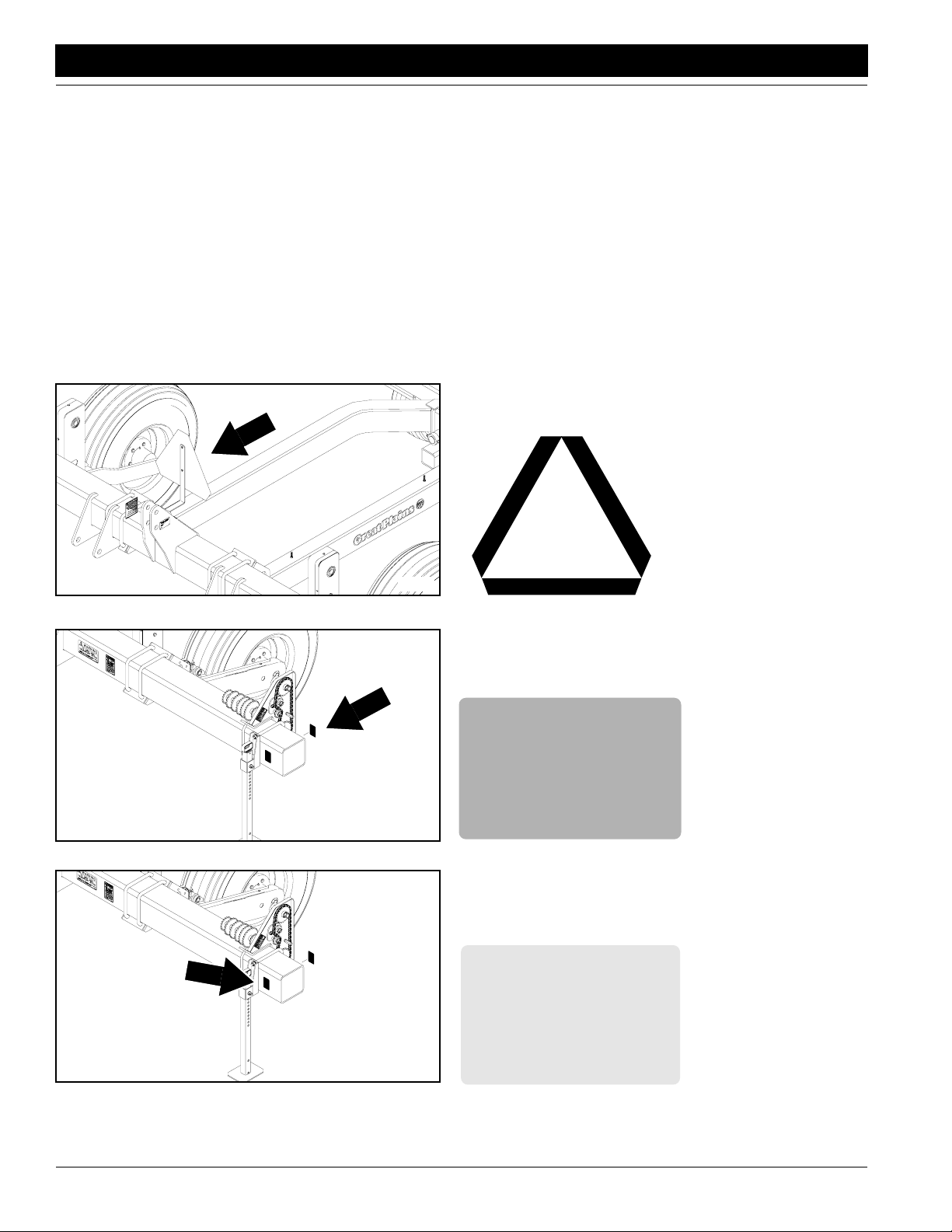
Slow Moving Vehicle Sign
818-230C
Red Reflector
Reflectors on both ends
of planter frame; two decals total
818-229C
Amber Reflector
Reflectors on both ends
of planter frame; two decals total
SR5030 Split-Row Planter 401-140M-A 4/12/05
4
Great Plains Mfg., Inc.
Important Safety Information
17724
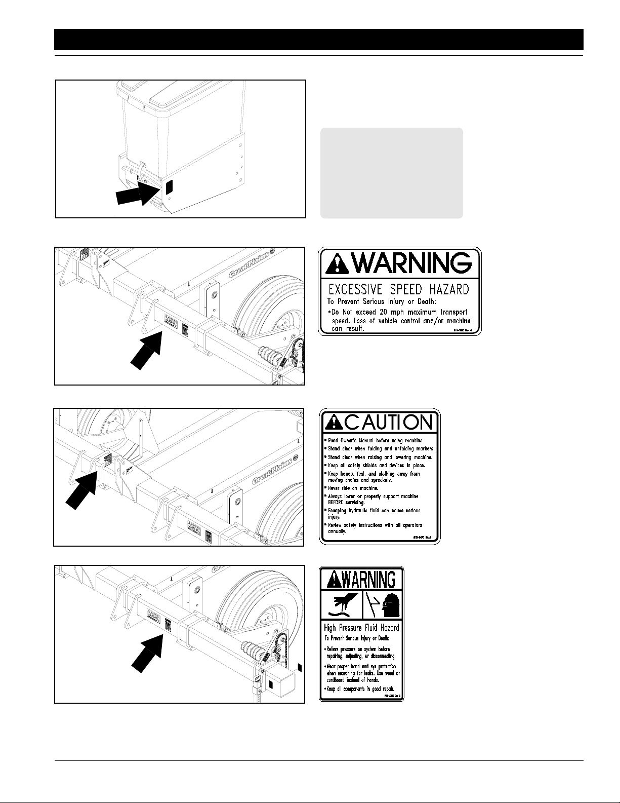
818-229C
Amber Reflector
Reflectors on outside row
units; two reflectors total
17725
17725
818-188C
Warning 20 MPH Trans
818-587C
Caution Operational
17725
4/12/05
818-339C
Warning High Pressure
SR5030 Split-Row Planter 401-140M-A
5
Introduction
Introduction
Great Plains Mfg., Inc.
Great Plains welcomes you to its growing family of new
product owners. This implement has been designed with
care and built by skilled workers using quality materials.
Proper setup, maintenance and safe oper ating pr actices
will help you get years of satisf actory use from the ma
chine.
-
Description of Unit
The SR5030 is a three-point-mounted planting implement.
The SR5030 has five row units spaced 30 inches apart.
The SR5030 is designed to pull a six-row , pull-type plant
er, splitting row width in half and planting 11 ro ws a pass .
Intended Usage
Use this unit with a six-row , pull-type planter to plant production-agriculture crops. Do not modify the planter for
use with attachments other than those specified by Great
Plains.
Using This Manual
This manual will familiarize you with safety, assembly, operation, adjustments, troubleshooting and maintenance.
Read this manual and follow the recommendations to help
ensure safe and efficient operation.
The information in this manual is current at printing. Some
parts may change to assure top performance.
Definitions
The following terms are used throughout this manual.
Right-hand and left-hand as used in this manual are deter-
mined by facing the direction the machine will tra v el while
in use unless otherwise stated.
IMPORTANT: A crucial point of information related to
the preceding topic. For safe and correct oper ation,
read and follow the directions provided before continuing.
NOTE: Useful inf ormation related to the preceding topic.
Owner Assistance
If you need customer service or repair parts, contact a
Great Plains dealer. The y ha ve trained personnel, repair
parts and equipment specially designed for Great Plains
products.
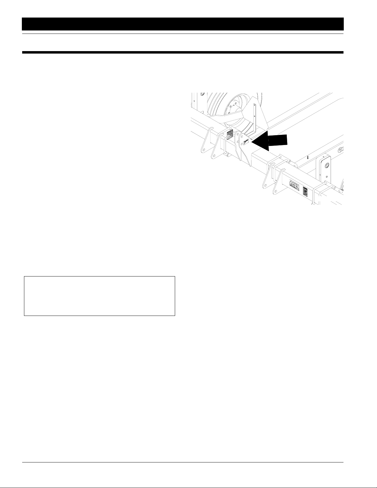
Your machine’s parts were specially designed and should
only be replaced with Great Plains parts. Always use the
serial and model number when ordering parts from your
Great Plains dealer. The serial-number plate is located on
the upper-link clevis as shown in Figure A.
-
17725
Figure A
Serial Number
Record your planter model and serial number here for quick
reference:
Model Number: _________________________________
Serial Number: _________________________________
Your Great Plains dealer wants you to be satisfied with
your new machine. If y ou do not understand an y part of
this manual or are not satisfied with the service received,
please take the following actions .
1. Discuss the matter with y our dealership service man-
ager. Mak e sure the y are aw are of an y prob lems so
they can assist you.
2. If you are still unsatisfied, seek out the owner or gen-
eral manager of the dealership.
3. For further assistance write to:
Product Support
Great Plains Mfg. Inc., Service Department
PO Box 5060
Salina, KS 67402-5060
SR5030 Split-Row Planter 401-140M-A 4/12/05
6
Great Plains Mfg., Inc.
Section 1 Preparation and Setup
Section 1 Preparation and Setup
This section will help you prepare your tractor and planter
for use. The planter must be hitched to a suitab le tr actor
and leveled before using it in the field.
Prestart Checklist
1. Read and understand “Important Safety Information” beginning on page 1.
2. Check that all working parts are moving freely, bolts
are tight, and cotter pins are spread.
3. Check that all grease fittings are in place and lubricated. Refer to Lubrication, “Maintenance and Lubri-
cation,” page 24.
4. Check that all safety decals and reflectors are legib le.
Replace if damaged. Refer to Safety Decals , “Impor
tant Safety Information,” page 4.
5. Inflate tires and tighten bolts as recommended in the
“Appendix,”
page 31.
Hitching Planters to Tractor
!
DANGER!
Y ou may be se ver ely injur ed or killed by being crushed between
the tractor and planter. Do not stand or place any part of your
body between planter and moving tractor. Stop tractor engine
and set park brake before installing hitch pins.
1. To prevent soil compaction on rows, set tractor
wheels at 75 inches center to center. For hillsides and
steep slopes, set tractor wheels as wide as possible
for maximum stability.
2. Adjust tractor lower links to maximize lifting height.
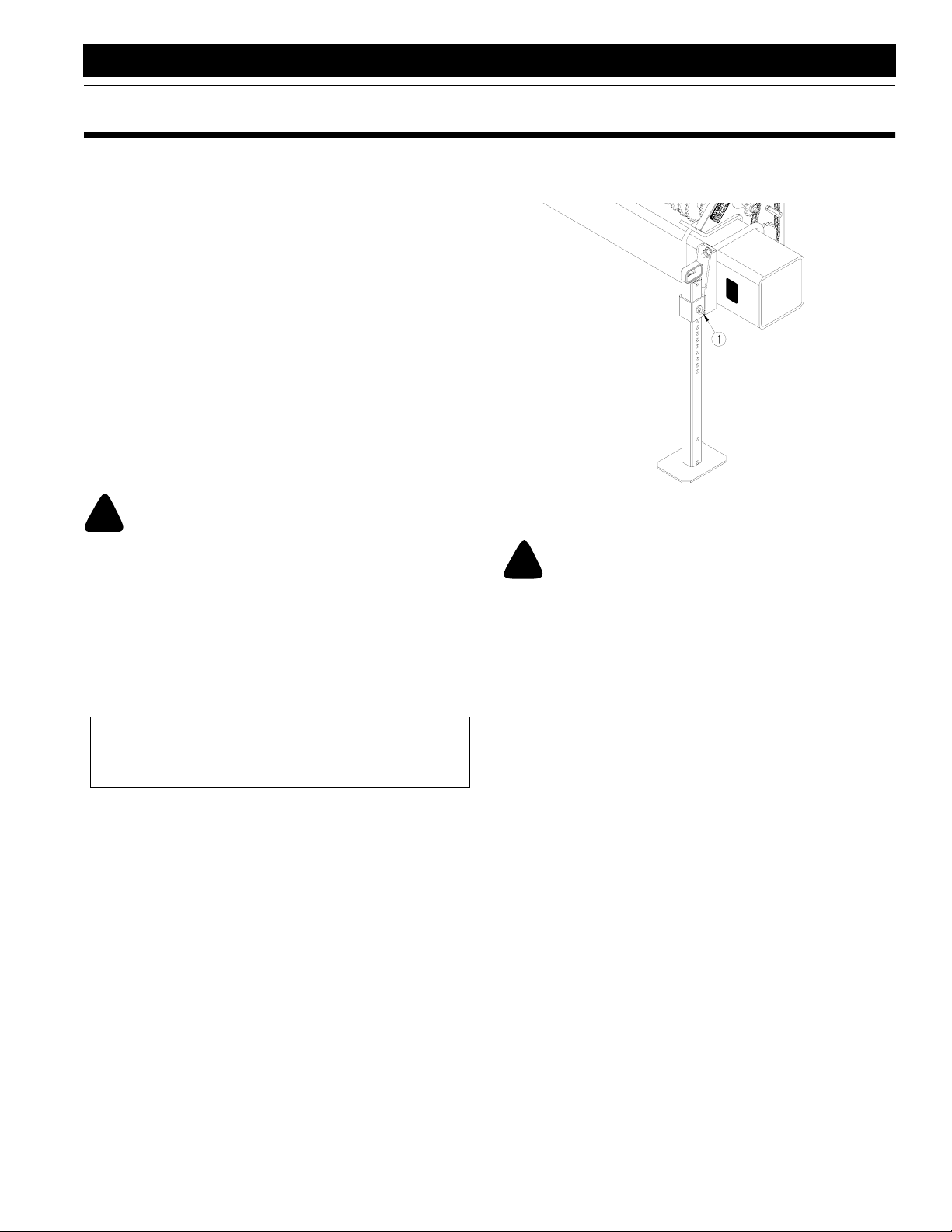
5. Raise planter. Remove pins (1) holding parking
stands and raise stands. Replace pins in lowest hole
of each stand.
-
Figure 1-1
Parking Stand
!
WARNING!
Escaping fluid under pressure can have sufficient pressure to
penetrate the skin. Check all hydraulic lines and fittings before
applying pressur e. Fluid escaping fr om a very small hole can be
almost invisible. Use paper or cardboard, not body parts, and
wear heavy gloves to check for suspected leaks. If injur ed, seek
medical assistance from a doctor that is familiar with this type
of injury. For eign fluids in the tissue must be surgically r emoved
within a few hours or gangrene will result.
17723
IMPORTANT: To keep the planter level make sure
the lower links are adjusted evenly.
Set tractor sway blocks to minimize side sway. Position tractor lift control in float position.
3. Back tractor up to planter. Align lower links with the
lower hitch holes on planter. Insert hitch pins and
spacers supplied with planter according to the catego
ry of your tractor. Lock pins in place.
4. Attach tractor top link in the lower hole for Category II
tractors. Attach tractor top link in the upper hole for
Category III tractors.
4/12/05
6. Hitch SR5030 to pull-type planter.
7. Connect hydraulic hoses f or pull-type planter to couplers on rear of SR5030. Connect hydraulic hoses f or
SR5030 to tractor outlets.
8. Connect planter electrical harness to SR5030 harness. Plug lead from SR5030 harness to the tractor
receptacle.
-
SR5030 Split-Row Planter 401-140M-A
7
Section 1 Preparation and Setup
Great Plains Mfg., Inc.
Leveling Planter
The planter must be level for the row units to function correctly. Before leveling the planter check tire pressures as
specified on Tire Inflation Chart, “Appendix,”
1. Check that planter is lev el from side to side. If not, adjust lower links of tractor three point to level planter.
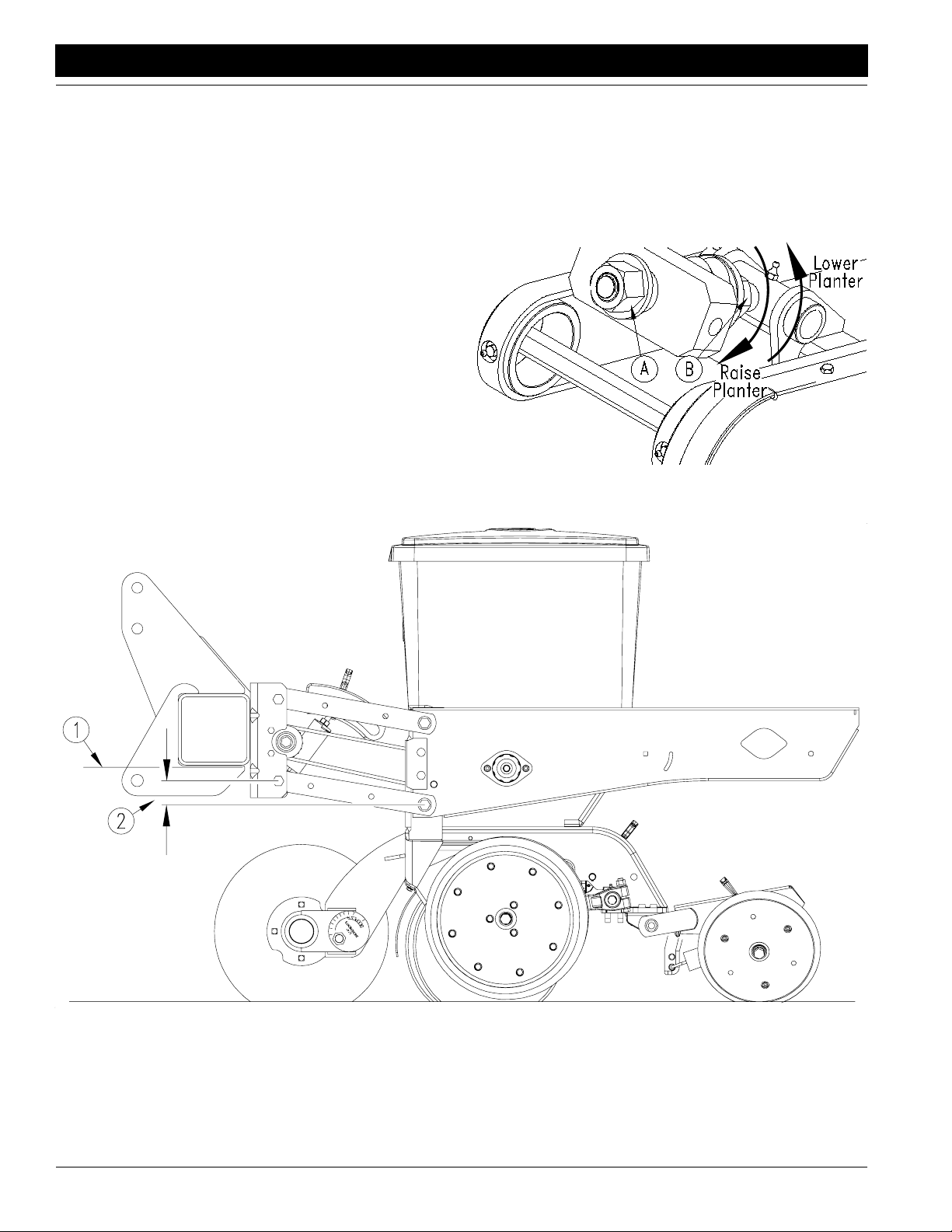
2. After setting row units to the proper planting depth,
park tractor and planter on level ground in the field.
Lower planter . If planter is lev el from front to back, the
bottom of the frame tube will be parallel to the ground
(1). See
Figure 1-2. If planter is not level, adjust upper
link on tractor three point to level planter.
3. Check that row-unit arms are parallel to the ground. If
row-unit arms are not parallel, adjust gauge-wheel
modules.
To find the amount of adjustment needed, measure
the vertical distance between the front and rear pivot
on the row-unit arms (2). See
Figure 1-2. Adjust both
gauge-wheel modules this amount.
page 30.
To adjust the gauge-wheel modules, see Figure 1-3.
Raise planter and loosen jam nut (A) on wheel module.
• To lower the planter, turn the nut (B) at the opposite
end of link counter-clockwise.
• To raise planter, turn nut (B) clockwise.
When finished adjusting, tighten jam nut.
10495
Figure 1-3
Adjusting Gauge-Wheel Modules
17886
Figure 1-2
Level Planter Front to Rear
SR5030 Split-Row Planter 401-140M-A 4/12/05
8
Great Plains Mfg., Inc.
Section 2 Operating Instructions
Section 2 Operating Instructions
This section covers general operating procedures . Experience, machine familiarity and the follo wing information will
lead to efficient operation and good working habits. Al
ways operate farm machinery with safety in mind.
-
Prestart Checklist
1. Carefully read “Important Safety Information,” beginning on page 1.
2. Lubricate planter as indicated under Lubrication,
“Maintenance and Lubrication,”
3. Check that planter tires are the correct size and properly inflated as indicated on Tire Inflation Chart, “Ap-
pendix,” page 30.
4. Check all bolts, pins and fasteners. T orque as specified on Torque Values Chart, “Appendix,” page 31.
5. Check the chains for proper tension and alignment as
shown in Maintenance, “Maintenance and Lubrica
tion,” page 20.
6. Check planter for worn or damaged parts. Repair or
replace them before going to the field.
page 24.
Field Operation
1. Perf orm all checks listed on Prestart Checklist, this
page.
2. Hitch planters to a tractor with sufficient weight and
horsepower . Ref er to Tractor Requirements , “Specifi
cations and Capacities,” page 30, and Hitching
Planters to T ractor , “Preparation and Setup ,” page 7.
3. Set and calibrate planting rate as explained under
Planting Rate, “Adjustments,”
4. Clear seed hoppers of foreign objects. Load seed
hoppers with clean seed. Add 1 teaspoon of graphite
to each seed hopper. Replace hopper lids.
5. Adjust down pressure on row units to match field conditions. Set row units to desired planting depth. Refer
to Row Unit Adjustments, “Adjustments,”
6. Check if planters are lev el. Refer to Leveling Planter ,
“Preparation and Setup,”
7. Lower planters, pull f orw ard and begin planting.
8. Always raise planters for field turns. Meters will stop
automatically as you raise planters.
page 14.
page 11.
page 8.
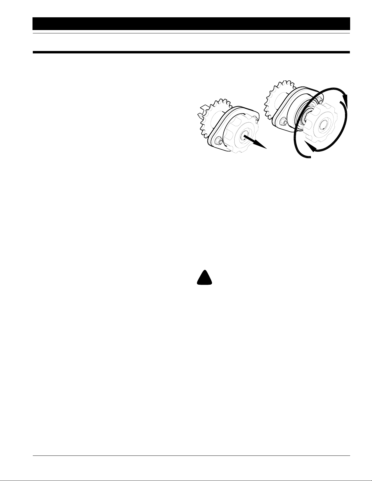
Meter Clutches
To disengage seed-hopper clutches, pull and rotate knobs
until meters are disengaged. See
17887
Figure 2-1
-
To engage clutches, pull and rotate knobs until meters
reengage.
Row Unit Operation
Never back up with row units in ground. If y ou do, check all
openers to be sure none are clogged. Always lift planter
out of ground when turning at ends of field rows and for
other short-radius turns.
For information on planting-depth and down-pressure
-
adjustments, refer to Row Unit Adjustments , “Adjust
ments,” beginning on page 11.
Meter Clutch
Figure 2-1.
Transporting
!
WARNING!
Towing the planter at high speeds can lead to loss of vehicle
control. Loss of vehicle control can lead to serious road acci
dents, injury and death. Do not exceed 20 mph. To maintain
steering control, ballast may need to be added to tractor front
end. To determine the amount of ballast required refer to your
tractor’s operator manual.
Before transporting the planter, chec k and practice the following items.
1. Check that planters are securely hitched to a sufficient
tractor. Refer to Tractor Requirements, “Specifica
tions and Capacities,” page 30 and Hitching Planters
to Tractor, “Preparation and Setup,” page 7.
-
-
-
4/12/05
SR5030 Split-Row Planter 401-140M-A
9
 Loading...