

Page 1
Great Plains Mfg., Inc.
Installation Instructions 1
Smartbox® Mount Kit
Yield Pro Planters
Used with:
• 2005+ Yield Pro
® 1225/1625
• Yield Pro® YP2425
General Information
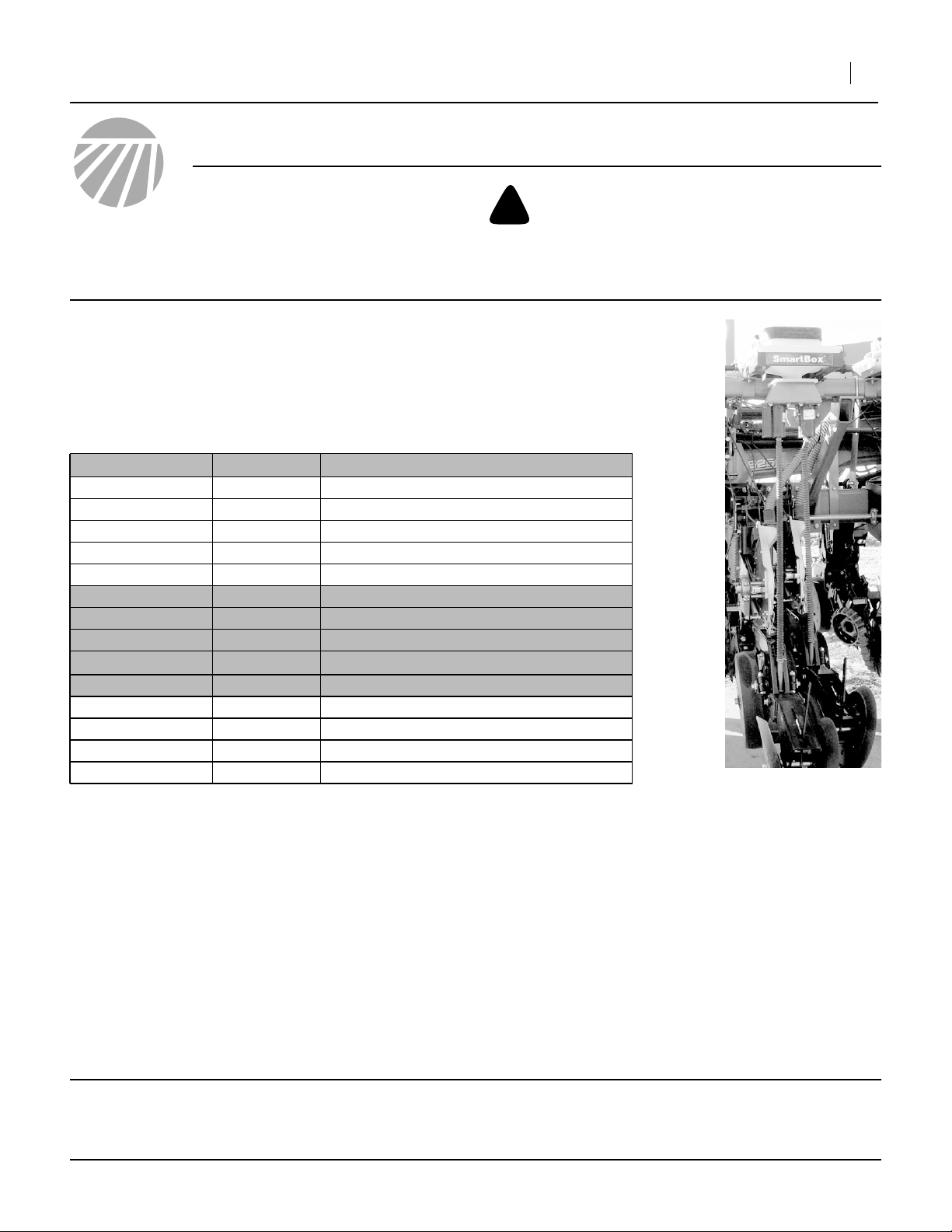
These instructions explain how to install the Smartbox®
Mount Kit. This kit provides the components necessary
to support mounting Smartbox® units on your Great
Plains planter. The kit does not include the Smartbox®
system itself, nor does it include the speed sensor (typically radar) required by the Smartbox monitor.
These instructions apply to:
Planter Model Uses Kit Kit Description
YP1225-1230
YP1225-16TR
YP1225-1820
YP1225-2315
YP1225-24TR
YP1625-1630
YP1625-2420
YP1625-24TR
YP1625-3115
YP1625-32TR
YP2425-2430
YP2425-3620
YP2425-4715
YP2425-48TR
403-196A
403-197A
403-196A
403-198A
403-199A
403-200A
403-201A
403-201A
403-218A
403-219A
403-218A
403-220A
YP30’ 15-30IN SMARTBOX MNT
(no kit presently available)
YP30’ 20IN SMARTBOX MNT KIT
YP30’ 30TR SMARTBOX MNT KIT
YP30’ 30TR SMARTBOX MNT KIT
YP40’ 15-30IN SMARTBOX MNT
YP40’ 20IN SMARTBOX MNT KIT
(no kit presently available)
YP40’ 30TR SMARTBOX MNT KIT
YP40’ 30TR SMARTBOX MNT KIT
YP60’ 15-30IN SMARTBOX MNT
YP60’ 20IN SMARTBOX MNT KIT
YP60’ 30TR SMARTBOX MNT KIT
YP60’ 30TR SMARTBOX MNT KIT
When you see this symbol, the subsequent instructions
and warnings are serious - follow without exception.
!
Your life and the lives of others depend on it!
25324
Before You Start
Each kit converts an entire planter. Inventory the contents per the “Kit Parts List” on page 18.
Although this kit can be installed before you have the
Smartboxes, Great Plains advises not undertaking this
upgrade until all components are at hand.
Review these instructions, and note which steps apply to
your planter model. For example, the Center Section
steps apply only to the YP2425.
Smartbox® is a registered trademark of AMVAC Chemical Corporation.
©Copyright 2005 Printed 12/12/2006 403-206M
Review the instructions provided by AMVAC, taking note
of where to merge those instructions with these. You may
want to make notations in these instructions for steps
required by AMVAC and not anticipated herein.
“Left” and “Right” are facing in the direction of machine
travel. An orientation rose in the line art illustrations
shows Left, Right, Front, Back, Up, Down.
Tools Required
• basic hand tools
Note: Assembly requires at least two people for the
longer and heavier parts.
Page 2
2 Smartbox® Mount Kit
Assembly Instructions
Great Plains Mfg., Inc.
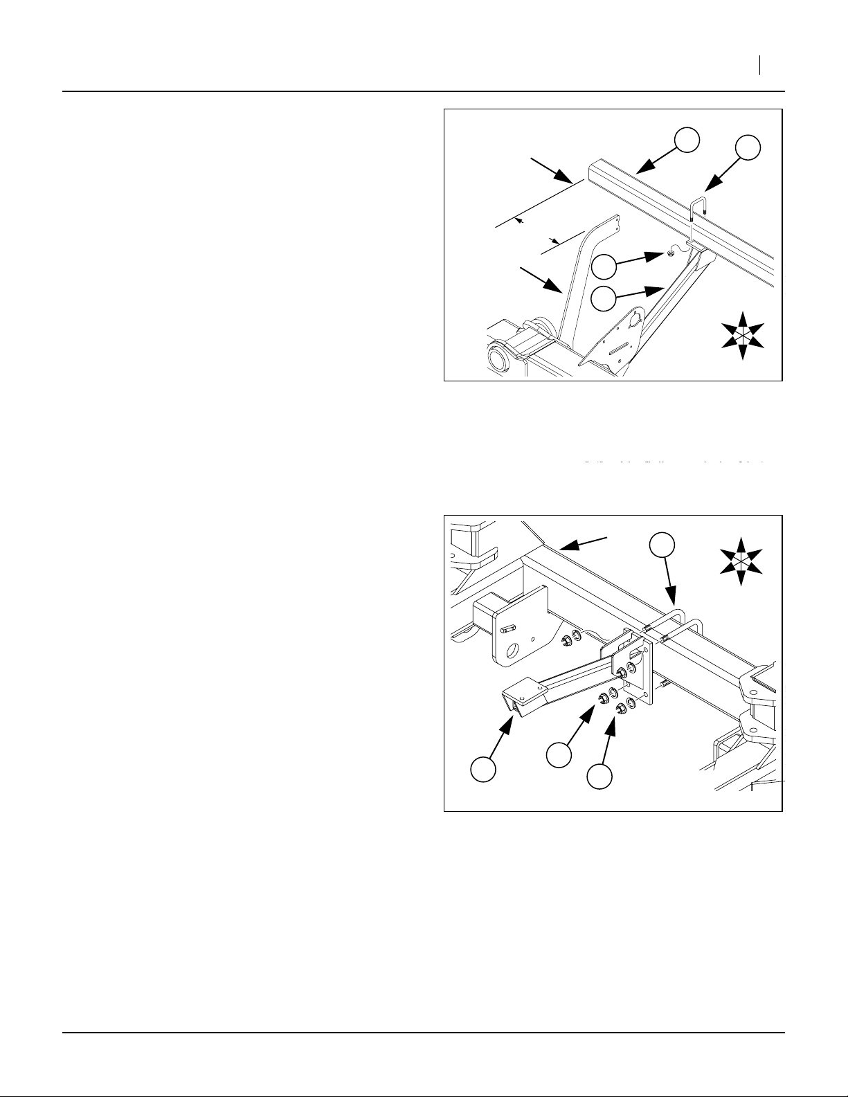
Wing Support Brackets
Outer End Wing Support Bracket (all Models)
Refer to Figure 1
1. Select:
one (14) 403-191H,
(SMARTBOX STANDOFF SUPPORT BKT)
two (35) 806-052C,
(U-BOLT 5/8-11 X 7 1/32 X 8 1/2)
four (33) 804-022C,
(WASHER LOCK SPRING 5/8 PLT),
and four (28) 803-021C,
(NUT HEX 5/8-11 PLT).
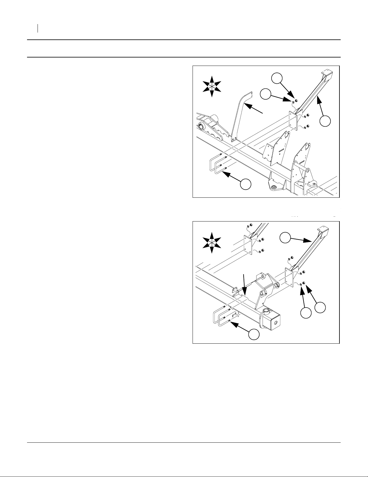
Attach the standoff support bracket (14) to Back of
toolbar of right-hand planter wing. Mount bracket
(14) as close to air pipe support ➀ as possible.
Note: It may be necessary to relocate hydraulic hose
support stand. Do not relocate row units.
Secure support bracket (14) to wing with U-bolts
(35), lock washers (33) and hex nuts (28).
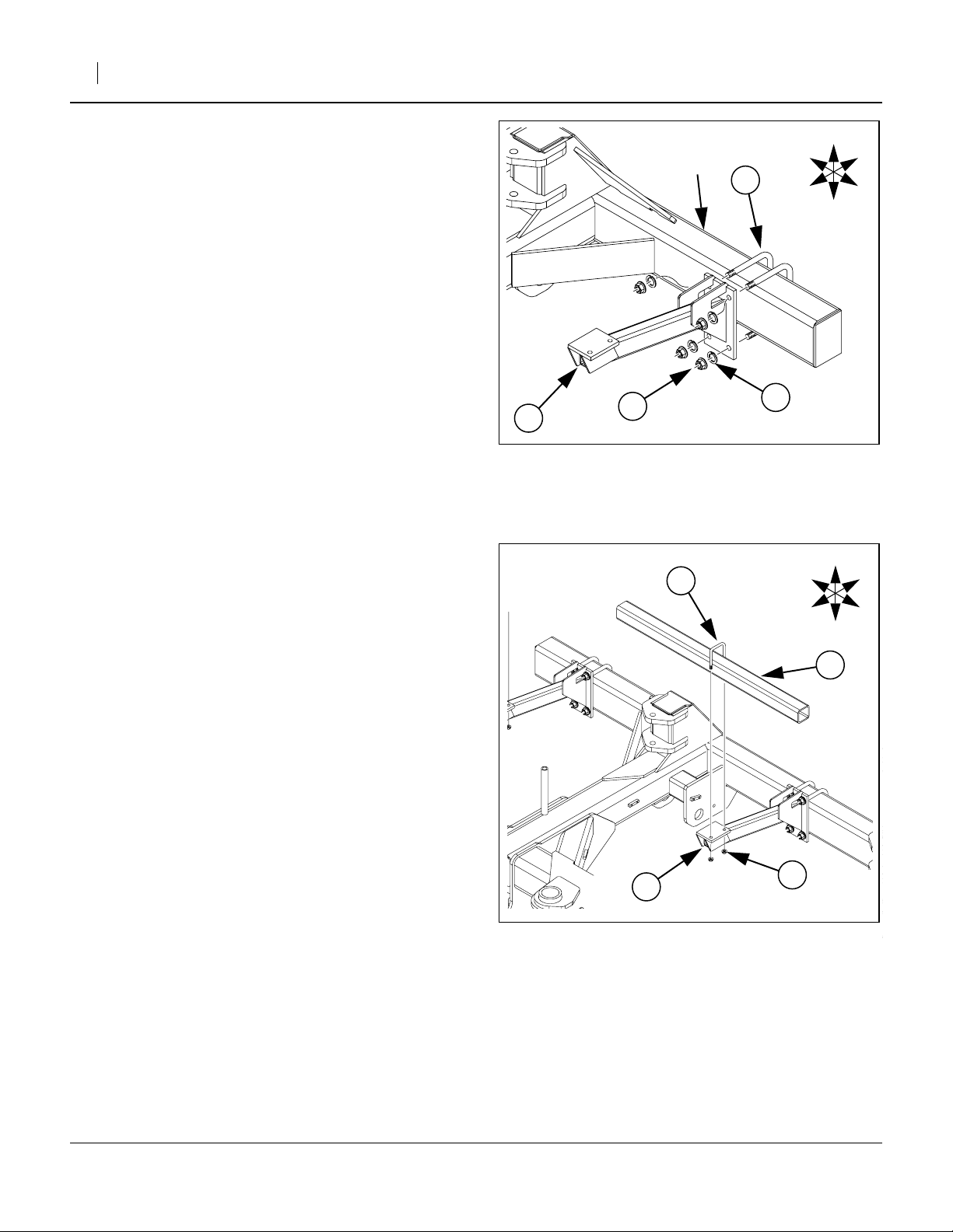
Pivot End Wing Support Bracket (all Models)
Refer to Figure 2
2. Select:
one (14) 403-191H,
(SMARTBOX STANDOFF SUPPORT BKT)
two (35) 806-052C,
(U-BOLT 5/8-11 X 7 1/32 X 8 1/2)
four (33) 804-022C,
(WASHER LOCK SPRING 5/8 PLT),
and four (28) 803-021C,
(NUT HEX 5/8-11 PLT).
Attach the standoff support bracket (14) to Back of
toolbar of right-hand planter wing. Mount bracket
(14) in slot ➀ below sequence valve.
If this toolbar slot is occupied by a row unit (for
example, on 15in row spacing), position the standoff support bracket at the first available position
inboard of that.
Secure support bracket (14) to wing with U-bolts
(35), lock washers (33) and hex nuts (28).
R
F
R
F
U
D
U
D
B
L
33
➀
35
Figure 1
Wing Outer End Bracket
B
L
➀
35
Figure 2
Wing Pivot End Bracket
28
14
24167
14
28
33
24167
403-206M 12/12/2006
Page 3
Great Plains Mfg., Inc.
Installation Instructions 3
Inner Wing Support Bracket (Models YP1225 & YP1625 only)
Refer to Figure 3
3. Select:
one (14) 403-191H,
(SMARTBOX STANDOFF SUPPORT BKT)
two (35) 806-052C,
(U-BOLT 5/8-11 X 7 1/32 X 8 1/2)
four (33) 804-022C,
(WASHER LOCK SPRING 5/8 PLT),
and four (28) 803-021C,
(NUT HEX 5/8-11 PLT).
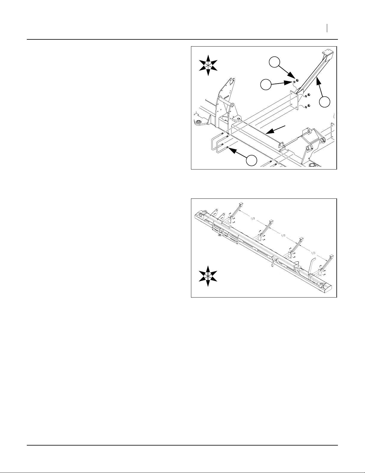
Attach the standoff support bracket (14) to Back of
toolbar of right-hand planter wing. Center bracket
(14) as best will fit approximately halfway between
the end brackets already installed. Do not relocate
row units.
Secure support bracket (14) to wing with U-bolts
(35), lock washers (33) and hex nuts (28).
Inner Wing Support Brackets (Model YP2425 only)
Refer to Figure 4
3. Select:
two (14) 403-191H,
(SMARTBOX STANDOFF SUPPORT BKT)
four (35) 806-052C,
(U-BOLT 5/8-11 X 7 1/32 X 8 1/2)
eight (33) 804-022C,
(WASHER LOCK SPRING 5/8 PLT),
and eight (28) 803-021C,
(NUT HEX 5/8-11 PLT).
Measure between the two brackets already
installed and find two locations approximately
the distance from each of them.
Attach a standoff support bracket (14) to Back of
toolbar of right-hand planter wing at each of those
locations. Do not relocate row units.
Secure support bracket (14) to wing with U-bolts
(35), lock washers (33) and hex nuts (28).
U
D
B
L
28
33
R
F
14
➀
35
Figure 3
Wing Inner Bracket
U
R
F
1
⁄
3
B
L
D
Figure 4
Wing Inner Brackets
24167
25232
Mount Brackets on Opposite Wing (All Models)
4. Repeat Step 1 through Step 3 on left-hand wing of planter.
12/12/2006 403-206M
Page 4
4 Smartbox® Mount Kit
Wing Support Tubes
Mount Tubes (Model YP1225 only)
Refer to Figure 5
5. Select:
one (15) 403-192H,
(SUPPORT TUBE WLDMNT - 12 ROW)
three (37) 806-066C,
(U-BOLT 1/2-13 X 3 1/32 X 4)
and six (30) 803-169C,
(NUT HEX FLG. LOCK 1/2-13 PLT.).
Align support tube (15) so a distance of 6 inches
exists between the planes defined by the end of air
pipe support ➀ and the support tube jog plate ➁.
Using U-bolts (37), attach support tube (15) to
standoff support brackets (14) with elevated end ➀
of support tube towards implement center.
Secure support tube (15) to each of three support
brackets (14) with hex lock nuts (30).
15
➀
6in
➁
30
Figure 5
YP1225 Wing Support Tube
Great Plains Mfg., Inc.
R
37
F
U
B
L
D
14
25325
Mount Tubes (Model YP1625 only)
Refer to Figure 6
5. Select:
one (13) 403-190H,
(SUPPORT TUBE WLDMNT)
three (37) 806-066C,
(U-BOLT 1/2-13 X 3 1/32 X 4)
and six (30) 803-169C,
(NUT HEX FLG. LOCK 1/2-13 PLT.).
Align support tube (13) so a distance of 6 inches
exists between end of air pipe support ➀ and support tube jog plate ➁.
Using U-bolts (37), attach support tube (13) to
standoff support brackets (14) with elevated end ➀
of support tube towards implement center.
Secure support tube (13) to each of three support
brackets (14) with hex lock nuts (30).
13
➀
6in
➁
30
Figure 6
YP1625 Wing Support Tube
37
R
F
U
B
L
D
14
25325
403-206M 12/12/2006
Page 5
Great Plains Mfg., Inc.
Mount Wing Tubes (Model YP2425 only)
Refer to Figure 7
5. Select:
one (19) 403-363D,
(TUBE SQ. 3.0X.25X260)
four (37) 806-066C,
(U-BOLT 1/2-13 X 3 1/32 X 4)
and eight (30) 803-169C,
(NUT HEX FLG. LOCK 1/2-13 PLT.).
Align support tube (19) so a distance of 20
exists between the planes defined by the air pipe
support ➀ and the support tube ➁.
Installation Instructions 5
19
➁
5
20
⁄
in
8
➀
5
⁄
in
8
30
14
R
37
U
B
Using U-bolts (37), attach support tube (19) to
standoff support brackets (14).
Secure support tube (19) to each of four support
brackets (14) with hex lock nuts (30).
(All Models)
6. Repeat Step 5 on opposite wing of planter.
(Models YP1225 & YP1625 only)
Skip to Step 16.
(Model YP2425 only)
Continue with Step 7.
Center Support Brackets (Model YP2425 only)
Center Support Arm
Refer to Figure 8
7. Select:
one (17) 403-225H,
(SMARTBOX SUPPORT ARM SHORT)
two (36) 806-053C,
(U-BOLT 5/8-11 X 7 1/32 X 6 1/2),
eight (33) 804-022C,
(WASHER LOCK SPRING 5/8 PLT) and
(28) 803-021C,
(NUT HEX 5/8-11 PLT).
Mount the support arm (17) on the rear-most
cross-tube ➀ of the center frame, at machine center, arm facing forward.
Loosely secure it with U-bolts (36), lock washers
(33) and nuts (28).
17
Figure 7
YP2425 Wing Support Tube
➀
36
28
33
Figure 8
Center Support Arm
F
R
F
L
D
24168
U
B
L
D
25202
12/12/2006 403-206M
Page 6
6 Smartbox® Mount Kit
Great Plains Mfg., Inc.
Center Section, Right/Left Support Arms (YP2425 only)
Refer to Figure 9
8. Select:
one (17) 403-225H,
(SMARTBOX SUPPORT ARM SHORT)
two (36) 806-053C,
(U-BOLT 5/8-11 X 7 1/32 X 6 1/2),
eight (33) 804-022C,
(WASHER LOCK SPRING 5/8 PLT) and
(28) 803-021C,
(NUT HEX 5/8-11 PLT).
Mount the support arm (17) on the right end of the
rear-most cross-tube ➀ of the center frame, arm
facing forward. Position it approximately 11 inches
from the tube end.
Secure it tightly with U-bolts (36), lock washers
(33) and nuts (28).
9. Repeat Step 8 for the left center.
Center Section, Center Support Tube (YP2425 only)
Refer to Figure 10
10. Select:
one (20) 403-364D,
(TUBE SQ. 3.0X.25X48.00)
one (37) 806-066C,
(U-BOLT 1/2-13 X 3 1/32 X 4), and
two (30) 803-169C,
(NUT HEX FLG. LOCK 1/2-13 PLT.).
Mount the support tube (20), at tube center. on the
center support arm (17) installed in Step 7.
Loosely secure it with U-bolt (37) and nut (30).
17
➀
28
Figure 9
Left/Right Center Section Arms
36
33
37
R
F
R
F
U
B
L
D
25202
U
B
L
D
20
17
Figure 10
Left/Right Center Section Arms
403-206M 12/12/2006
30
25202
Page 7

Great Plains Mfg., Inc.
Installation Instructions 7
Center Section, Right/Left Support Tubes (YP2425 only)
Refer to Figure 11
11. Select:
one (20) 403-364D,
(TUBE SQ. 3.0X.25X48.00)
one (37) 806-066C,
(U-BOLT 1/2-13 X 3 1/32 X 4), and
two (30) 803-169C,
(NUT HEX FLG. LOCK 1/2-13 PLT.).
Mount the support tube (20), at tube center. on the
right support arm (17) installed in Step 8.
Loosely secure it with U-bolt (37) and nuts (30).
12. Repeat Step 11 for the left arm installed in Step 9.
Right/Left Stiffener Bars (YP2425 only)
Refer to Figure 12
The stiffener bars connect the center and right/left support tubes. In doing so, the bars pass between the fold
cylinders.
13. Select:
one (21) 403-365D,
(STIFFENER BAR)
two (37) 806-066C,
(U-BOLT 1/2-13 X 3 1/32 X 4), and
four (30) 803-169C,
(NUT HEX FLG. LOCK 1/2-13 PLT.).
Mount the stiffener bar (21) so that it joins the center and right tubes installed in Step 10 and Step
11. Align the end of each tube with first bend in the
bar.
Note: The bar mounts on top of the tubes, and the bend
in the bar is down, to maintain clearance from
cylinders during planter operations.
Secure the bar to the tubes with the U-bolt (37)
and nuts (30).
14. Adjust the location of the outer support arm to
keep it centered under the tube. Tighten the nuts at
the arm base.
15. Repeat Step 13 and Step 14 for the left tube.
37
17
Figure 11
Left/Right Center Tubes
30
37
Figure 12
Center Section Tube Stiffener
21
30
R
F
R
F
U
B
L
D
20
25203
U
B
L
D
25204
12/12/2006 403-206M
Page 8

8 Smartbox® Mount Kit
Prepare Smartboxes for Installation
Depending on planter configuration, some or all rows
may require installation of meter splitters before mounting
the Smartbox units on the new toolbar tubes.
| Machine Right
SP
Mount and Row Unit Assignments
Individual Row Units
|
Machine Left
1 2 3 4 5 6 7 8 9 10 11 12 13 14 15 16 17 18 19 20 21 22 23 24
1
0
1
0
1
0
SP
BB
1
0
SP
BB
1
0
SP
BB
1
1
B
1
B
1
B
1
B
1
L
1
L
1
R
1
R
1
B
1
B
1
B
1
B
0
LL
SP
1
1
L
0
1
1
R
0
SP
RR
1
0
SP
BB
1
0
SP
BB
1
0
SP
BB
1
BB
B
SP
BB
B
SP
BB
B
SP
BB
B
-
LL
SP
L
-
LL
SP
L
SP
RR
R
SP
RR
R
SP
BB
B
SP
BB
B
SP
BB
B
SP
BB
B
1 2 3 4 5 6 7 8 9 10 11 12 13 14 15 16 17 18 19 20 21 22 23 24 25 26 27 28 29 30 31 32
SP
BB
SP
BB
SP
BB
SP
BB
1
B
LL
SP
1
B
1
B
LL
SP
1
B
1
B
SP
1
1
1
1
1
1
1
1
1
1
1
RR
B
L
SP
RR
L
R
SP
BB
R
B
SP
BB
B
B
SP
BB
B
B
SP
BB
B
Great Plains Mfg., Inc.
Find your planter in the following table and note where
splitters (if any) are used. Note also meter pointing bias
near pivots and cylinder interruption points.
SP
1
0
1
0
1
0
1
0
1
0
1
0
SP
BB
1
0
SP
BB
1
B
SP
1
B
-
0
1
0
1
0
1
0
1
0
1
0
1
0
1
0
1
0
1
0
1
0
1
0
1
0
1
0
1
0
1
B
SP
B
B
SP
B
-
SP
BB
B
-
SP
B
-
SP
B
-
SP
L
-
SP
L
-
SP
R
-
SP
R
-
SP
B
-
SP
B
-
SP
B
-
SP
B
-
SP
B
-
SP
B
BB
BB
LL
LL
RR
RR
BB
BB
BB
BB
BB
BB
1
B
1
B
1
B
1
B
1
B
1
B
1
B
1
B
1
B
1
B
1
B
1
B
1
B
1
B
1
B
1
B
1
B
1
B
1
B
1
B
1
B
1
B
1
B
1 2 3 4 5 6 7 8 9 10 11 12 13 14 15 16 17 18 19 20 21 22 23 24 25 26 27 28 29 30 31 32 33 34 35 36 37 38 39 40 41 42 43 44 45 46 47 48
1
B
0
SP
BB
1
0
SP
BB
1
0
SP
BB
1
0
SP
BB
1
0
SP
BB
1
0
SP
BB
1
0
SP
BR
1
0
LB
SP
1
0
SP
BB
1
0
SP
BB
1
0
SP
BB
1
0
SP
BB
1
0
SP
BB
1
0
SP
BB
1
0
SP
BB
1
0
SP
BB
1
BB
B
SP
BB
B
SP
BB
B
SP
BB
B
SP
BB
B
SP
BB
B
SP
BB
B
SP
BB
B
SP
BB
B
SP
BB
B
SP
BB
B
SP
BB
B
SP
BB
B
SP
BB
B
SP
BB
B
SP
BB
B
SP
BB
B
SP
BB
B
SP
BB
B
SP
BB
B
SP
BB
B
SP
BB
B
-
B
-
B
SP
BB
SP
BB
Row Unit Number (from machine left to right)1Unitary: One Smartbox connected to one row unit (no splitter)SPSplitter: One Smartbox connected to two row units via splitter0Null: No connection to this row unit
49
Meter Pointing: Some boxes cannot be mounted directly over the row unit(s) they serve.
Mount meter so that its exit port faces primarily Right(R), Left(L) or Back(B).
RLB
Pivot: Division point between wings, or between wings and center section
Cylinder: Division point in YP2425 center section where tube is interrupted by cylinders
Model
Planter
Tabl e
Legend
Kit
403-206M 12/12/2006
-196A -1230
403- YP1225
-197A -1820
-196A -2315
-198A -24TR
-199A -1630
403- YP1625
-200A -2420
-199A -3115
-201A -32TR
-218A -2430
403- YP2425
-219A -3620
-218A -4715
-220A -48TR
Page 9

Great Plains Mfg., Inc.
Preparing Mounts
Installation Instructions 9
Items for these steps supplied by AMVAC:
➀ Smartbox frames
➁ Smartbox base containers & fasteners
➂ Meters
➃ Gaskets
Preparing Unitary (no Splitter) Mounts
Refer to Figure 13 (base container shown with Smartbox frame - do
not assemble to frame at this time).
For each mount point which has no splitter, the meter is
attached to the Smartbox base container. Orient meter
exit ports per the table on page 8.
16. Select:
four (25) 802-004C,
(HHCS 1/4-20X3/4 GR5),
four (32) 804-007C,
(WASHER FLAT 1/4 SAE PLT), and
four (29) 803-088C (not shown),
(NUT HEX LOCK 1/4-20 FLG).
Position gasket ➃ between Smartbox base container ➁ and meter ➂. Insert bolt (25) through flat
washer (32). Attach meter ➂ to base container ➁
using nut (29) (not shown). Do not mount base
container on frame ➀ at this time.
17. Repeat Step 16 for each unitary Smartbox.
Preparing Split Mounts
Refer to Figure 14 (base container shown with Smartbox frame - do
not assemble to frame at this time)
For each mount point which has a splitter, the splitter is
attached to the Smartbox base container and two
meters are attached to the splitter.
18. Select:
one (16) 403-202H,
(SMARTBOX METER SPLITTER WLDMNT),
twelve (25) 802-004C,
(HHCS 1/4-20X3/4 GR5),
twelve (32) 804-007C,
(WASHER FLAT 1/4 SAE PLT), and
twelve (23) 800-163C,
(CLIP U-TYPE NUT 1/4-20 SLF-RET).
19. Insert all bolts (25) through flat washers (32).
20. Insert a clip nut (23) at each of the fastener openings in the top of the splitter (16). Insert the clip
with the flat side Up.
➁
➀
➃
➂
U
F
L
R
B
D
Figure 13
Unitary Pre-Assembly
U
D
B
R
➁
➀
F
L
23
16
32
25
25326
➃
23
23
➃
➂
32
➂
25
Figure 14
Split-Mount Pre-Assembly
25327
21. Insert a clip nut (23) at each of the fastener openings in the bottom of the splitter (16). Insert the clip
with the flat side Down.
22. Position a gasket ➃ between Smartbox base container ➁ and splitter (16). Using four bolts and
washers, attach splitter (16) to base container.
12/12/2006 403-206M
23. Position a gasket ➃ between a meter ➂ and the
splitter (16). Attach meter to splitter with four bolts
and washers. Repeat for second meter.
24. Repeat Step 18 through for Step 23 each splitter.
Page 10

10 Smartbox® Mount Kit
Mount Smartbox Frames
Refer to Figure 15 (which illustrates normal back-of-tube mounting)
The Smartbox frames ➀ mount to the new tubes ➁ with
3
⁄
a pair of clamps (18),
bolts (26), and flange lock nuts (31) provided in the
mount kit.
Most of the clamps are placed on the Back side of the
tube, but on the YP1225 and YP1625, two (pair) must
be placed on the Front side of the tube.
For model YP2425, skip to Step 40.
in long bolts (27),
8
3
⁄
in short
8
Great Plains Mfg., Inc.
27
➁
26
➀
18
U
L
F
18
YP1225 and 1625 Near-Pivot Mounting
Refer to Figure 16
Due to clearance from other components, the four
inner-most Smartboxes cannot be placed directly over
the row units they serve, and must be to the outside,
with meter hoses canted inward.
Identify the four Smartbox assemblies with meter exit
ports biased Left or Right and set them aside from the
assemblies with ports pointing Back. If you didn’t build
four assemblies with biased ports, pick four assemblies
and re-point the meters.
B
D
R
Figure 15
Typical Frame Mount
31
25328
Figure 16
YP1225/1625 Inner Mounts
403-206M 12/12/2006
24169
Page 11

Great Plains Mfg., Inc.
Installation Instructions 11
Mount Left Inner-Most YP1225/1625 Smartbox
Refer to Figure 17 and Figure 20
25. Select:
one ➀ Smartbox frame,
two (18) 403-319D,
(SMART BOX HOLD DOWN CLAMP),
two (27) 802-223C,
(HHCS 3/8-16X4 GR5),
two (26) 802-079C,
(HHCS 3/8-16X1 1/4 GR5), and
four (31) 803-209C,
(NUT FLANGE LOCK 3/8-16 PLT).
If the base container is already installed on the
SmartBox frame, it may be necessary to remove it
to gain access to the mounting holes.
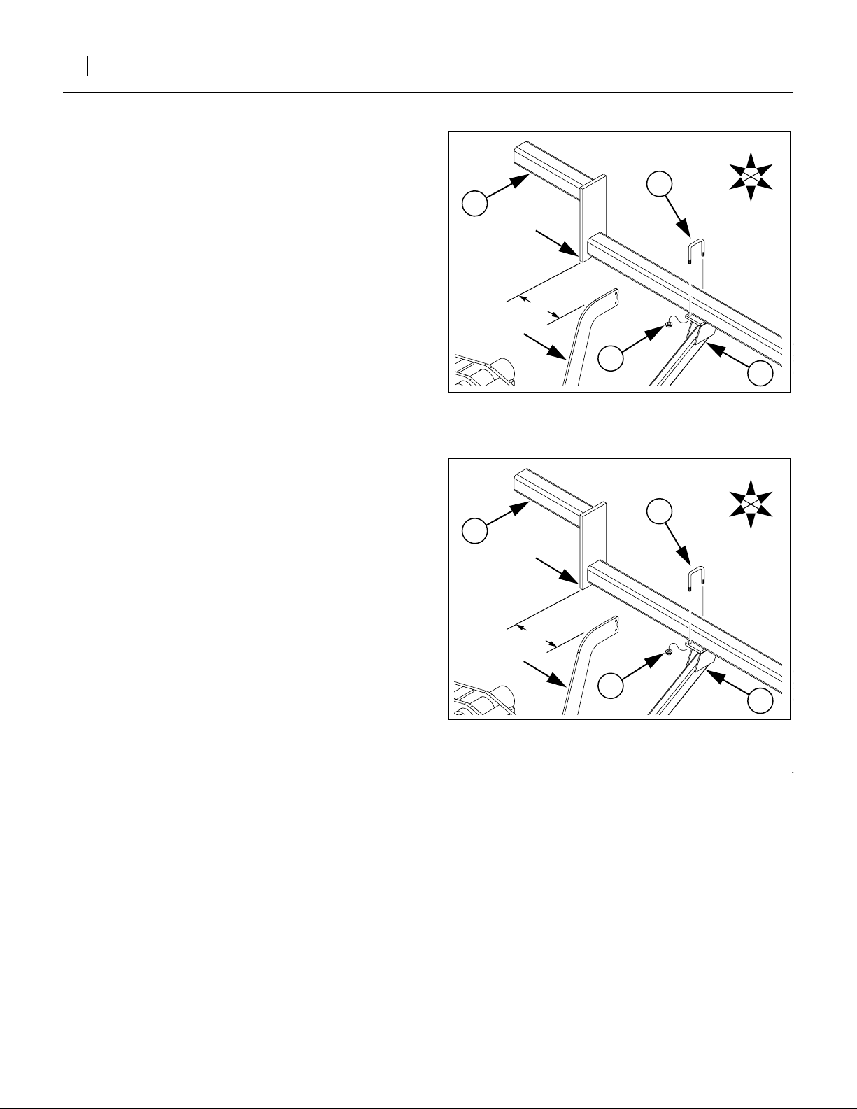
26. Insert a 1
mounting hole
the shorter end of a clamp (18) over the bolt (26)
and add a flange lock nut (31). Put only a few turns
on the nut.
27. Position the frame ➀ about 4in from the end of the
inner-most end of the new tube ➂, or directly next
to the air pipe support plate.
28. Insert a 4in bolt (27) in the slotted hole ➃ just forward of center on each side of the frame ➀, and
then down through the hole in the clamp (18), and
add a flange lock nut (31). Put only a few turns on
the nut.
29. Alternately tighten the lock nuts (31), keeping the
Smartbox frame ➀ and the base of the clamp (18)
parallel to the tube ➂ top and bottom, and the front
of the clamp snug against the front of the tube.
30. Repeat Step 26 through Step 29 for the other side
of the frame ➀.
31. Position Smartbox base container/meter or
container/splitter/meter assembly ➄ in the frame
1
⁄
in bolt (26) in the forward slotted
4
➁ on one side of the frame ➀. Slip
➀, having the meter ports biased to the Right, and
secure with fasteners provided by AMVAC.
Mount Right Inner-Most YP1225/1625 Smartbox
32. Repeat Step 25 through Step 31 for the innermost
Smartbox on the right side of the machine, using a
Smartbox base container/meter or container/
splitter/meter assembly with the meter exit port(s)
biased to the Left.
➀
➀
➄
27
➁
➃
31
Figure 17
Near-Pivot Mounting
26
31
Figure 18
YP1225/1625 Inner-Most
18
➃
➂
➂
26
18
L
B
U
F
R
D
25329
➁
31
26
18
24176
12/12/2006 403-206M
Page 12

12 Smartbox® Mount Kit
Mount Second Inner YP1225/1625 Smartboxes
Refer to Figure 19 and Figure 20
The components for this step are identical to those of
Step 25 through Step 32. There are two procedural differences from mounting the inner-most frames:
33. Insert a 1
just forward of center ➁ on one side of the frame
1
⁄
in bolt (26) in the slotted mounting hole
4
➀. Slip the shorter end of a clamp (18) over the
bolt (26) and add a flange lock nut (31). Put only a
few turns on the nut.
34. Position the frame ➀ on the tube ➂ and against
the jog plate ➃.
35. Insert a 4in bolt (27) in the forward slotted hole ➄
of the frame ➀, and then down through the hole in
the clamp (18), and add a flange lock nut (31). Put
only a few turns on the nut.
36. Repeat Step 33 through Step 35 for the other side
of the frame ➀.
37. Position Smartbox base container/meter or
container/splitter/meter assembly ➅ in the frame
➀, having the meter ports biased to the Right, and
secure with fasteners provided by AMVAC.
B
Great Plains Mfg., Inc.
27
➂
➄
26
➀
➁
18
U
D
F
R
YP1225/1625 2nd Mount
18
31
Figure 19
25328
L
38. Slide the complete assembly fully forward and
against the jog plate ➃, and the tube ➂, before
final tightening.
39. Repeat Step 33 through Step 38 for the second
innermost Smartbox on the right side of the
machine, using a Smartbox base container/meter
or container/splitter/meter assembly with the meter
exit port(s) biased to the Left.
➂
➃
➅
Figure 20
YP1225/1625 2nd Inner
24169
403-206M 12/12/2006
Page 13

Great Plains Mfg., Inc.
Installation Instructions 13
YP2425 Center Section Smartbox Frames
For ease of access, mount the two inner-most center
section Smartbox frames first.
Note: Whether the entire center section will have four or
six Smartboxes total, the tube between the cylinders always has two.
Note: Meters may need to have one or both exit ports
biased Left or Right. Consult the table on page 8
before installing base container/[splitter]/meter
assemblies.
YP2425 Center Section Box Frames
Refer to Figure 21 and Figure 22
40. Select:
one ➀ Smartbox frame,
two (18) 403-319D,
(SMART BOX HOLD DOWN CLAMP),
two (27) 802-223C,
(HHCS 3/8-16X4 GR5),
two (26) 802-079C,
(HHCS 3/8-16X1 1/4 GR5), and
four (31) 803-209C,
(NUT FLANGE LOCK 3/8-16 PLT)
41. Insert a 1
near center ➁ on one side of the frame ➀. Slip the
shorter end of a clamp (18) over the bolt (26) and
add a flange lock nut (31). Put only a few turns on
the nut.
42. Position the frame ➀ Left of center on the tube ➂
per in Figure 21, clamp (18) to machine front.
43. Insert a 4in bolt (27) in the forward slotted hole ➄
of the frame ➀, and then down through the hole in
the clamp (18), and add a flange lock nut (31). Put
only a few turns on the nut.
44. Repeat Step 33 through Step 35 for the other side
of the frame ➀.
1
⁄
in bolt (26) in the slotted mounting hole
4
➈
Figure 21
Center Section Box Frames
27
➂
26
➄
➁
18
R
F
U
B
L
D
25207
➀
45. Position Smartbox base container/meter or
container/splitter/meter assembly ➅ in the frame
➀, having the meter ports biased per the table on
page 8, and secure with fasteners provided by
AMVAC.
46. Repeat Step 41 through Step 45 for the inner-most
center section box just Right of center.
47. Repeat Step 41 through Step 46 for the two box
frames to the outside of the center tube of the center section.
48. Repeat Step 41 through Step 45 for the box frames on the outside tubes of the center section.
Note: If the outer tubes have only one box, mount it to the outside, as shown at ➈ in Figure 21.
12/12/2006 403-206M
F
R
U
D
B
L
YP2425 Center Mount
18
31
Figure 22
25328
Page 14

14 Smartbox® Mount Kit
Mount Wing Box Frames
(all Models)
Mounting wing box frames does not have the same considerations as for frames near or at center. There is
some additional flexibility in placement on the tubes, so
review where each is to go. it might be useful to mark
the centerline of each proposed position with masking
or painting tape.
For unitary mounts, position as close as possible to
directly above the row unit to be served. For split
mounts, position as close as possible to halfway
between the row units to be served.
Repeat Step 49 through Step 54 until all frames are
mounted:
Refer to Figure 23
49. Select:
one ➀ Smartbox frame,
two (18) 403-319D,
(SMART BOX HOLD DOWN CLAMP),
two (27) 802-223C,
(HHCS 3/8-16X4 GR5),
two (26) 802-079C,
(HHCS 3/8-16X1 1/4 GR5), and
four (31) 803-209C,
(NUT FLANGE LOCK 3/8-16 PLT)
50. Insert a 1
just forward of center ➁ on one side of the frame
➀. Slip the shorter end of a clamp (18) over the
bolt (26) and add a flange lock nut (31). Put only a
few turns on the nut.
1
⁄
in bolt (26) in the slotted mounting hole
4
B
Great Plains Mfg., Inc.
27
➂
➄
26
➀
➁
18
U
D
F
18
R
Figure 23
Outboard Wing Mount
31
25328
L
51. Position the frame ➀.
52. Insert a 4in bolt (27) in the forward slotted hole ➄
of the frame ➀, and then down through the hole in
the clamp (18), and add a flange lock nut (31). Put
only a few turns on the nut.
53. Repeat Step 33 through Step 35 for the other side
of the frame ➀.
54. Position Smartbox base container/meter or
container/splitter/meter assembly ➅ in the frame
➀, having the meter ports biased per the table on
page 8, and secure with fasteners provided by
AMVAC.
403-206M 12/12/2006
Page 15

Great Plains Mfg., Inc.
Install T-Banders
Refer to Figure 24, which depicts two variations of T-bander
The T-Bander (39) is the distribution nozzle for the
Smartbox system. It mounts under the row unit, through
a dedicated pair of holes ➀ at the hinge point between
the opener and the press wheel assembly.
The T-Bander assembly consists of four parts:
(39) 817-655C (T-BANDER)
(12) 116-001D (T-BANDER TUBE)
(22) 800-126C (CLAMP WRM DRV #5 SS (.44-.70))
(34) 805-185C (PIN COTTER .186 WIRE DIA)
If your application requires a longer nozzle on the Tbander, an extension boot is available as Great Plains
part number 816-511C.
Repeat Step 55 through Step 58 for each row unit
served by a Smartbox meter.
Refer to Figure 24 and Figure 25
55. Attach T-Bander tube (12) to T-Bander (39).
Slide either end of tube fully down over neck of TBander.
25330
Installation Instructions 15
➀
12
22
➃
39
Figure 24
T-Bander w/Tube Attached
➀
34
24178
Note grooves ➃ for cotter pin, but do not attach
cotter pin at this time.
56. Place clamp (22) over neck of T-Bander, and position above groove ➃. Tighten clamp.
57. Insert T-Bander assembly ➀ through holes ➁ from
beneath row unit. Align it so that the exit port is
side-to-side.
Refer to Figure 26
58. Insert cotter pin (34) in slot ➂ so that it engages
grooves ➃ on T-Bander. If your T-bander has multi-
ple grooves for the cotter pin, consult AMVAC for a
height recommendation.
34
➂
Figure 25
Insert T-Bander
➁
34
24180
➀
Figure 26
T-Bander w/Cotter Pin
12/12/2006 403-206M
24181
Page 16

16 Smartbox® Mount Kit
Attach Delivery Hoses
Delivery hoses connect the exit ports of the Smartbox
meters to the T-Banders.
Although your kit includes one hose (38) for each meter/
T-Bander, these hoses are a common length which is
long enough for side-shifted mounts near machine center. This makes them too long for most outboard row
units. It will be necessary to trim some length from most
hoses. Do this after attaching them to the meters, at
Step 63.
Attach Hoses To Meters
Great Plains Mfg., Inc.
➀
22
38
Repeat Step 57 through Step 62 for each meter.
Refer to Figure 27
59. Select:
one (38) 816-358C,
(SGS HOSE 122 RIBS), and
one (22) 800-126C,
(CLAMP WRM DRV #5 SS (.44-.70))
60. Slide a clamp (22) over the end of a hose (38).
Unscrew the worm drive if the clamp does not fit
loosely on the hose.
61. Slide one end of the hose (38) fully onto the exit
port of the meter ➀.
62. Adjust the position of the clamp to be
end of the hose, and tighten worm drive. Do not
overtighten.
3
⁄
in from the
8
Trim Hoses to Length
Before beginning these steps, determine which hoses
go to which row units. This is particularly important for
15in planters, where only the “corn row” units are
served by a Smartbox.
63. Temporarily place the lower end of each hose over
its T-Bander tube at the row unit. Start with the
outer-most rows. At the inner-most rows, the hoses
are likely to cant inward as they descend.
64. Raise the planter.
The row units need to be at their lowest position in
order to determine the shortest hose length.
For each row unit, repeat Step 65 through Step 62:
65. Lift the hose off the T-Bander tube.
66. Determine the shortest length that allows the hose
to reach the meter.
67. Add 1
68. Cut the hose at that point.
1
⁄
inches.
2
Figure 27
Hose Attachment at Meter
24172
403-206M 12/12/2006
Page 17

Great Plains Mfg., Inc.
Attach Hoses to T-Banders
Refer to Figure 28
For each row unit, repeat Step 65 through Step 62:
69. Select:
one (24) 800-321C,
(HOSE CLAMP NO.12 3/4 ID)
70. Place the hose clamp (24) over the T-Bander tube
(12).
71. Slide the cut hose (38) by at least 1
1
⁄
in.
2
72. Using hose clamp pliers, open the hose clamp (24)
and lift it up about
3
⁄
in onto the hose. Release to
4
clamp hose in position.
Install Other Smartbox Components
Refer to AMVAC documentation for instructions regarding Controller, MTU, wiring harness and radar connection.
Installation Instructions 17
24
Figure 28
Hose Attach at T-bander
38
12
24181
Installation Reference Information
Torque Values
Fastener/Fitting Ft-Lbs N-m
1
⁄4-20 GR5
3
⁄8-16 GR5
1
⁄2-13 U-bolt
5
⁄8-11 U-bolt
811
31 42
105 76
205 150
12/12/2006 403-206M
Page 18

Great Plains Mfg., Inc.
18 Smartbox® Mount Kit
Kit Parts List
Smartbox® Mount Kits
The part call-out numbers in this list match all Figures in the installation instructions. Your kit includes:
(Callout)
Part No.
(11) 403-206M 1 1 1 1 11111
(12) 116-001D 12 18 24 16 24 32 24 36 48
(13) 403-190H 0 0 02220 0 0
(14) 403-191H 6 6 6 6 66888
(15) 403-192H 2 2 2 0 0 0 0 0 0
(16) 403-202H 08120121601824
(17) 403-225H 0 0 0 0 0 0333
(18) 403-319D 24 20 24 32 24 32 48 36 48
(19) 403-363D 0 0 0 0 0 0222
(20) 403-364D 0 0 0 0 0 0333
(21) 403-365D 0 0 0 0 0 0222
(22) 800-126C 24 18 24 32 48 64 48 72 96
(23) 800-163C 0 96 144 0 144 192 07296
(24) 800-321C 12 18 24 16 24 32 24 36 48
(25) 802-004C 48 104 144 64 144 192 07296
(26) 802-079C 24 20 24 32 24 32 48 36 48
(27) 802-223C 24 20 24 32 24 32 48 36 48
(28) 803-021C 24 24 24 24 24 24 44 44 44
(29) 803-088C 48 0 0640 0 0 0 0
(30) 803-169C 12 12 12 12 12 12 30 30 30
(31) 803-209C 48 40 48 64 48 64 96 72 96
(32) 804-007C 48 104 144 64 144 192 07296
(33) 804-022C 24 24 24 24 24 24 44 44 44
(34) 805-185C 12 18 24 16 24 32 24 36 48
(35) 806-052C 12 12 12 12 12 12 16 16 16
(36) 806-053C 0 0 0 0 0 0666
(37) 806-066C 6 6 6 6 6 6 15 15 15
(38) 816-358C 12 18 24 16 24 32 24 36 48
(39) 817-655C 12 18 24 16 24 32 24 36 48
-196A -197A -198A -199A -200A -201A -218A -219A -220A
Quantity per 403-
(Callout) Part Description
(11) This manual
(12) T-BANDER TUBE
(13) SUPPORT TUBE WLDMNT
(14) SMARTBOX STANDOFF SUPPORT BKT
(15) SUPPORT TUBE WLDMNT - 12 ROW
(16) SMARTBOX METER SPLITTER WLDMNT
(17) SMARTBOX SUPPORT ARM SHORT
(18) SMART BOX HOLD DOWN CLAMP
(19) TUBE SQ. 3.0X.25X260
(20) TUBE SQ. 3.0X.25X48.00
(21) STIFFENER BAR
(22) CLAMP WRM DRV #5 SS (.44-.70)
(23) CLIP U-TYPE NUT 1/4-20 SLF-RET
(24) HOSE CLAMP NO.12 3/4 ID
(25) HHCS 1/4-20X3/4 GR5
(26) HHCS 3/8-16X1 1/4 GR5
(27) HHCS 3/8-16X4 GR5
(28) NUT HEX 5/8-11 PLT
(29) NUT HEX LOCK 1/4-20 FLG
(30) NUT HEX FLG. LOCK 1/2-13 PLT.
(31) NUT FLANGE LOCK 3/8-16 PLT
(32) WASHER FLAT 1/4 SAE PLT
(33) WASHER LOCK SPRING 5/8 PLT
(34) PIN COTTER .186 WIRE DIA
(35) U-BOLT 5/8-11 X 7 1/32 X 8 1/2
(36) U-BOLT 5/8-11 X 7 1/32 X 6 1/2
(37) U-BOLT 1/2-13 X 3 1/32 X 4
(38) SGS HOSE 122 RIBS
(39) T-BANDER
Great Plains Manufacturing, Inc.
Corporate Office P.O. Box 5060
Salina, Kansas 67402-5060 USA
403-206M 12/12/2006
 Loading...