

Page 1
1 S3T & Reel Great Plains Manufacturing, Inc.
S3T & Reel Update
Using This Manual
This manual was written to help you assemble and prepare the new finishing attachment. The manual includes
instructions for assembly and setup. Read this manual
and follow the recommendations for safe, efficient and
proper assembly and setup.
The information in this manual is current at printing.
Some parts may change to assure top performance.
Definitions
The following terms are used throughout this manual.
A crucial point of information related to the preceding topic.
Read and follow the directions to remain safe, avoid serious
damage to equipment and ensure desired field results.
Note: Useful information related to the preceding topic.
Right-hand and left-hand as used in
this manual are determined by facing
the direction the machine will travel
while in use unless otherwise stated.
An orientation rose in some line art
illustrations shows the directions of: Up,
Back, Left, Down, Front, Right
R
F
U
B
L
D
R
FigureSpacer:
L
Figure 1
Right / Left
42091
550-487M 12/22/2011
Page 2

2 S3T & Reel Great Plains Manufacturing, Inc.
Models Covered
8318DVN 18-Foot 3-section
8324DVN 24-Foot 3-section
7548DV 48-Foot 5-section
8328DV 28-Foot 3-section
8537DV 37-Foot 5-section
8544DV 44-Foot 5-section
An operator’s and parts manual is also provided with the
machine or can be viewed on Great Plains web site.
Read and understand “Important Safety Information”
and “Operating Instructions” in the operator’s manual
before assembling the machine. Refer to the parts manual for proper part’s identification. As a reference, keep
the operator’s and part’s manual on hand while assembling.
Document Family
550-466M Operator Manual
550-466P Parts Manual
550-353M Operator Manual
550-353P Parts Manual
550-221M Operator Manual
550-221P Parts Manual
Tools Required
• Basic Hand Tools
• Torque Wrench
• Fork Truck, Overhead Hoist or Loader
Pre-assembly Checklist
1. Before assembling, read and understand “Important
Safety Information” in front part of operator’s manual.
2. Have at least two people on hand while assembling.
550-487M 12/22/2011
Page 3

Great Plains Manufacturing, Inc. S3T & Reel Update 3
12/22/2011 550-487M
Page 4

4 S3T & Reel Great Plains Manufacturing, Inc.
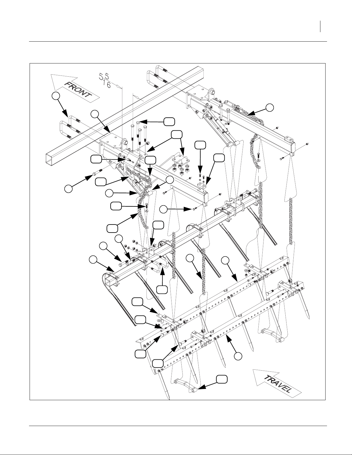
Assembly
S3T Bar & Spike Drag
Refer to Figure 2
1. Attach arm assemblies to rear bar of machine with
3/4 x 4 1/32 x 4 1/2 u-bolts , 3/4 lock washers and
1
2
nuts.
Note: See Layout drawings pages 8-16 for proper arm
placements.
2. Mount front bar assembly to rear of adjustable link
and link , with 5/8 x 3 1/2 hex bolts , 5/8 top
4 5 6
3
lock nuts.
3. Attach top of 15 link drag chains to bottom side of
arm assemblies with 3/8 x 1 1/4 hex bolts 3/8
1 8
7
lock washers and 3/8 nuts.
4. Slide lower link of 15 link drag chains into slot on
spike drag bar bracket , secure with 3/8 x 2 1/2 hex
bolt , and top lock nut.
10
5. Align holes in harrow link with holes in spike drag
bar bracket , secure with 5/8 x 2 7/8 special bolts
and 5/8 top lock nuts.
12
9
6. Attach two plates (one on top and one on bottom) of arm assembly . Note measurement of 5 5/
9
11
13
1
16” from rear of spring to front of plate . Attach key
7
13
hole plate to outside of plates key hole plates .
Secure with 5/8 x 6 hex botlts , 5/8 lock washers
14 13
15
and 5/8 nuts.
7. Attach safety chain spring loop to inside of key
hole plate with 1/2 x 1 1/2 hex bolt , 1/2 flat
14 17
16
washer, 1/2 lock washer and 1/2 nut.
8. Attach one end of 25 link pull chain to slotted hole
in key hole plate .
14
18
9. Attach other end of chain to front drag link assembly
with 7/16 x 1 1/2 hex bolt , 7/16 flat washers
19 20
(one on bolt and one under plate) and 7/16 nylock
nut.
10. Attach polyurethane bumper to top side of arm
assemblies with 5/16 x 1/2 hex bolts and 5/16
1
21
22
flat washers.
11. Attach front bar mount assembly with 1/2 x 2 1/2 x
3 1/2 u-bolts , 1/2 lock washers and 1/2 nuts.
24
23
12. All bolts may be tightened to specs, See “Torque
Values Chart” on page 22.
550-487M 12/22/2011
Page 5
Great Plains Manufacturing, Inc. Assembly 5
2
1
1
15
13
22
17
14
6
5
20
18
16
4
8
23
21
6
6
3
7
9
24
19
10
12
9
12
11
ull4:
S3T Bar & Spike Drag Assembly
12/22/2011 550-487M
Figure 2
42089
Page 6

6 S3T & Reel Great Plains Manufacturing, Inc.
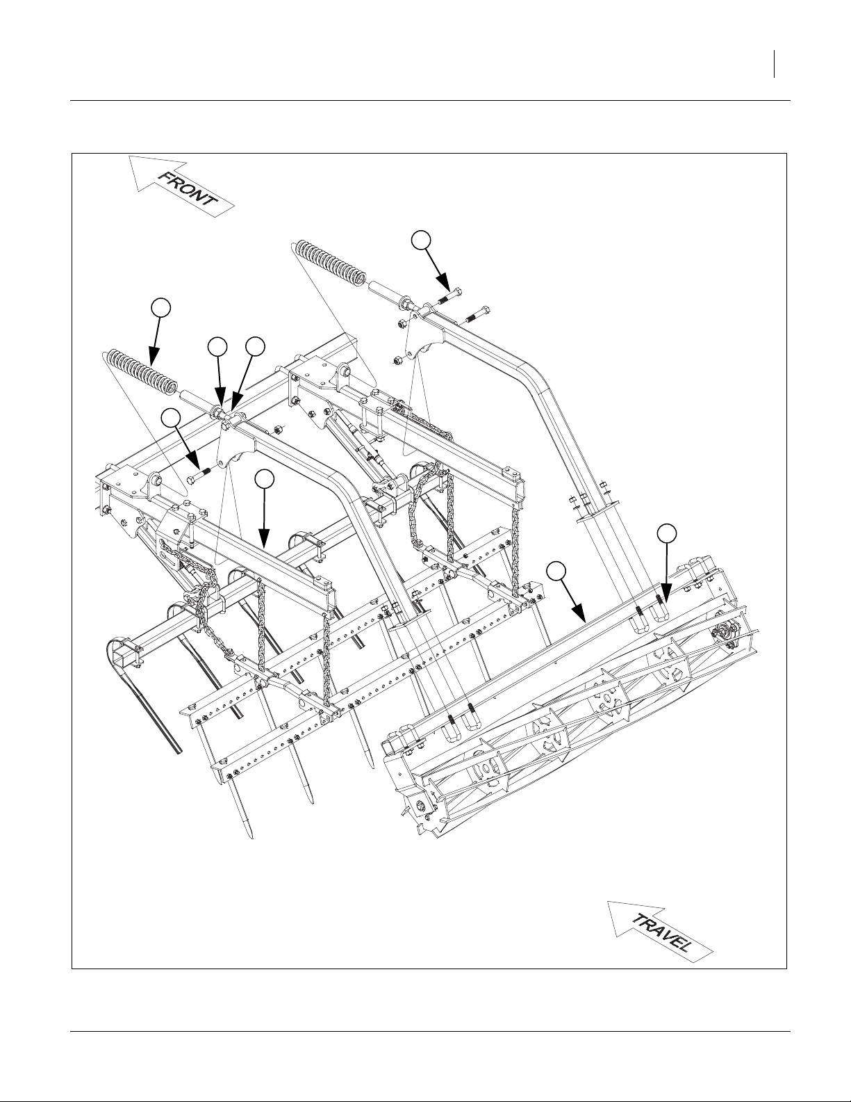
Reel Following S3T
Refer to Figure 3
1. Slide spring over tube of reel arm assembly .
Align other end of spring to tube on front plate of
arm assembly and let the rest of the reel arm
assembly rest on the pad towards rear of arm
assembly .
2. Secure reel arm assembly to arm assembly with
3/4 x 4 hex bolt and 3/4 top lock nut. Tighten top
1 2
1
3
2
3
2 3
4
lock nut snug but do not torque as arm needs to
pivot.
Note: Adjust nut on reel arm assembly snug to hold
5
3
spring on round tube on front plate of arm assem-
bly . When rest of drag is installed, set the pre-
3
load pressure on spring, See “5-Section Fold
Catch Assembly” on page 8.
Note: See Layout drawings pages 8-16 for proper reel
placements.
3. Attach reel assemblies to rear plates of reel arm
assembly with 3/4 x 4 1/32 x 4 1/2 u-bolts , 3/4
2 7
6
lock washers and 3/4 nuts.
4. All u-bolts may be tightened to specs, See “Torque
Values Chart” on page 22.
550-487M 12/22/2011
Page 7
Great Plains Manufacturing, Inc. Assembly 7
4
1
2
5
4
3
7
6
ull4:
12/22/2011 550-487M
Figure 3
Reel Assembly
42090
Page 8

8 S3T & Reel Great Plains Manufacturing, Inc.
5-Section Fold Catch Assembly
Refer to Figure 3
Note: The catch assembly is only used on 5-section
outer wings. Be sure to mount the bent catch
towards center of machine on both sides.
1. Attach catch assembly to inside of arm assembly
with the mounting plates . Secure with 1/2 x 3 1/2
1
2
hex bolts in top holes and 1/2 x 3 hex bolts in
3 4
bottom holes, 1/2 lock washers and 1/2 nuts.
2. Align arm assembly 3 7/8” from rear of arm to rear of
rear angle iron as shown.
3. All bolts may be tightened to specs, See “Torque
Values Chart” on page 22.
550-487M 12/22/2011
Page 9

Great Plains Manufacturing, Inc. Assembly 9
2
3
4
1
ull4:
12/22/2011 550-487M
Figure 4
Fold Catch
42150
Page 10

10 S3T & Reel Great Plains Manufacturing, Inc.
Reel Spring Pre-Load
Refer to Figure 5
4. Adjust nut to where spring is just making contact with front plate .
5. Turn nut another 1” further on spring rod to set
pre-load on spring.
1 2
2
1 4
3
2
1
4
Null4:
Figure 5
Reel Spring Pre-Load
42094
550-487M 12/22/2011
Page 11

Great Plains Manufacturing, Inc. Assembly 11
12/22/2011 550-487M
Page 12

12 S3T & Reel Great Plains Manufacturing, Inc.
8318DVN
FigureSpacer:
42082
FigureSpacer:
550-487M 12/22/2011
Page 13

Great Plains Manufacturing, Inc. Assembly 13
8321DVN
FigureSpacer:
42409
FigureSpacer:
12/22/2011 550-487M
Page 14

14 S3T & Reel Great Plains Manufacturing, Inc.
8324DVN
FigureSpacer:
42083
FigureSpacer:
550-487M 12/22/2011
Page 15

Great Plains Manufacturing, Inc. Assembly 15
8328DV
FigureSpacer:
42084
FigureSpacer:
12/22/2011 550-487M
Page 16

16 S3T & Reel Great Plains Manufacturing, Inc.
8537DV
FigureSpacer:
42085
FigureSpacer:
550-487M 12/22/2011
Page 17

Great Plains Manufacturing, Inc. Assembly 17
8537DV
FigureSpacer:
42086
FigureSpacer:
12/22/2011 550-487M
Page 18

18 S3T & Reel Great Plains Manufacturing, Inc.
88544DV
FigureSpacer:
420887
FigureSpacer:
550-487M 12/22/2011
Page 19

Great Plains Manufacturing, Inc. Assembly 19
88544DV
FigureSpacer:
420888
FigureSpacer:
12/22/2011 550-487M
Page 20

20 S3T & Reel Great Plains Manufacturing, Inc.
7548DV
FigureSpacer:
42092
FigureSpacer:
550-487M 12/22/2011
Page 21

Great Plains Manufacturing, Inc. Assembly 21
7548DV
FigureSpacer:
42093
FigureSpacer:
12/22/2011 550-487M
Page 22

22 S3T & Reel Great Plains Manufacturing, Inc.
Torque Values Chart
Bolt
Size
in-tpi
1
⁄4-20
1
⁄4-28
5
⁄16-18
5
⁄16-24
3
⁄8-16
3
⁄8-24
7
⁄16-14
7
⁄16-20
1
⁄2-13
1
⁄2-20
9
⁄16-12
9
⁄16-18
5
⁄8-11
5
⁄8-18
3
⁄4-10
3
⁄4-16
7
⁄8-9
7
⁄8-14
1-8
1-12
1
1
⁄8-7
1
1
⁄8-12
1
⁄4-7
1
1
⁄4-12
1
3
⁄8-6
1
3
1
⁄8-12
1
1
⁄2-6
1
1
⁄2-12
Bolt Head Identification
Grade 2 Grade 5 Grade 8 Class 5.8 Class 8.8 Class 10.9
a
b
d
N-m
ft-lb
7.4 11 16
8.5 13 18
15 24 33
17 26 37
27 42 59
31 47 67
43 67 95
49 75 105
66 105 145
75 115 165
95 150 210
105 165 235
130 205 285
150 230 325
235 360 510
260 405 570
225 585 820
250 640 905
340 875 1230
370 955 1350
480 1080 1750
540 1210 1960
680 1520 2460
750 1680 2730
890 1990 3230
1010 2270 3680
1180 2640 4290
1330 2970 4820
N-m N-m
5.6 8 12
61014 5 811
11 17 25 12 19 27
13 19 27 13 21 29
20 31 44 24 39 53
22 35 49 29 45 62
32 49 70 42 67 93
36 55 78 44 70 97
49 76 105 66 77 105
55 85 120 68 105 150
70 110 155 73 115 160
79 120 170 105 165 230
97 150 210 115 180 245
110 170 240 145 230 300
170 265 375 165 260 355
190 295 420 205 325 450
165 430 605 230 480 665
185 475 670 355 560 780
250 645 910 390 610 845
275 705 995 705 1120 1550
355 795 1290 785 1240 1710
395 890 1440 1270 1950 2700
500 1120 1820 1380 2190 3220
555 1240 2010
655 1470 2380
745 1670 2710
870 1950 3160
980 2190 3560
Bolt Head Identification
Bolt
Size
ft-lb ft-lb ft-lb ft-lb ft-lb
mm x pitch
M 5 X 0.8
M 6 X 1
M 8 X 1.25
M 8 X 1
M10 X 1.5
M10 X 0.75
M12 X 1.75
M12 X 1.5
M12 X 1
M14 X 2
M14 X 1.5
M16 X 2
M16 X 1.5
M18 X 2.5
M18 X 1.5
M20 X 2.5
M20 X 1.5
M24 X 3
M24 X 2
M30 X 3.5
M30 X 2
M36 X 3.5
M36 X 2
a. in-tpi = nominal thread diameter in inches-threads per inch
b. N· m = newton-meters
c. mm x pitch = nominal thread diameter in mm x thread pitch
d. ft-lb = foot pounds
c
5.8 8.8 10.9
N-m N-m N-m
357
71115
17 26 36
18 28 39
33 52 72
39 61 85
58 91 125
60 95 130
90 105 145
92 145 200
99 155 215
145 225 315
155 240 335
195 310 405
220 350 485
280 440 610
310 650 900
480 760 1050
525 830 1150
960 1510 2100
1060 1680 2320
1730 2650 3660
1880 2960 4100
946
Torque tolerance + 0%, -15% of torquing values. Unless otherwise specified use torque values listed above.
25199m
25199
Disc or Coulter Gang Bolt Torque 1 1/2”-6 650-750 Foot-pounds (175 lbs on 4’ cheater).
550-487M 12/22/2011
 Loading...