

Page 1

Operators / Parts Manual
Turbo-Till SeriesII 1200TT-4000TT
Rolling Harrow & Reel Attachments
Read the operator’s manual entirely. When you see this symbol, the
subsequent instructions and warnings are serious - follow without
!
exception. Your life and the lives of others depend on it!
©Copyright 2009 Printed 2/4/2009 586-216M
Page 2

General Information Great Plains Mfg., Inc.
General Information
Great Plains Manufacturing, Inc. provides this
publication “as is” without warranty of any kind,
either expressed or implied. While every
precaution has been taken in the preparation of
this manual, Great Plains Manufacturing, Inc.
assumes no responsibility for errors or omissions.
Neither is any liability assumed for damages
resulting from the use of the information contained
herein. Great Plains Manufacturing, Inc. reserves
the right to revise and improve its products as it
sees fit. This publication describes the state of this
product at the time of its publication, and may not
reflect the product in the future.
Printed in the United States of America.
For your convenience, record your Serial Number,
Model Number and the Date Purchased in the
spaces provided below. Have this information
available when calling your Great Plains
Authorized Dealer.
Owner’s Information
Name:_______________________________
Address _____________________________
City______________State ____ Zip _______
Phone_______________________
Name of Dealership ____________________
Dealer’s Name ________________________
Address _____________________________
City______________State ____ Zip _______
Phone_______________________
SeriesII 1200TT-4000TT Turbo-Till Attachments 586-216M 10/25/2007
Serial Number ___________________
Model Number ___________________
Date Purchased __________________
Page 3

Great Plains Mfg., Inc. Table of Contents
Table of Contents
Using This Manual .............................................2
Introduction ........................................................2
Section 1 Safety Rules ........................................3
General Operation & Repair .........................3
Transporting .................................................3
Safety Decals ................................................3
Section 2 Assembly & Set-Up ............................4
Rolling Harrow Assembly ............................4
Reel Following the Rolling Assembly .........5
Rear Stand Assembly ...................................6
Section 3 Operating Instructions ......................8
Prior to Going to the Field ............................8
General Operating Instructions and
In-Field Adjustments ...............................8
Section 4 Maintenance & Lubrication .............9
General Maintenance ....................................9
Lubrication ...................................................9
Section 5 Parts.....................................................10
Rolling Harrow Assembly ............................10
Reel Following Rolling Harrow Assembly .. 12
Rear Jack Stand ............................................ 14
Section 6 Machine Layouts ............................... 16
1200TT Rolling Harrow................................ 16
1200TT Reel following Rolling Harrow.......17
1500TT Rolling Harrow................................ 18
1500TT Reel following Rolling Harrow.......19
1800TT Rolling Harrow................................ 20
1800TT Reel following Rolling Harrow.......21
2400TT Rolling Harrow................................ 22
2400TT Reel following Rolling Harrow.......23
3000TT Rolling Harrow................................ 24
3000TT Reel following Rolling Harrow.......26
4000TT Rolling Harrow................................ 28
4000TT Reel following Rolling Harrow.......30
Appendix .............................................................32
Torque Values for Common Bolt Sizes ....... 32
Tire Inflation Chart ...................................... 32
10/25/2007 SeriesII 1200TT-4000TT Turbo-Till Attachments 586-216M
1
Page 4

Using This Manual Great Plains Mfg., Inc.
Using This Manual
For your safety and to help in developing a better
understanding of your equipment we highly
recommend that you read the operator sections of
this manual. Reading these sections not only
provides valuable training but also familiarizes you
Introduction
This manual has been prepared to instruct you in
the safe and efficient operation of your Finishing
Attachment. Read and follow all instructions and
safety precautions carefully.
The parts on your Finishing Attachment have
been specially designed and should only be
replaced with genuine Great Plains parts.
Therefore, should your Finishing Attachment
require replacement parts go to your Great
Plains Dealer.
The right hand and left hand as used throughout
this manual is determined by facing in the
direction the machine will travel when in use
unless otherwise stated.
!
!
The SAFETY ALERT SYMBOL indicates that
there is a potential hazard to personal safety
involved and extra safety precautions must be
taken. When you see this symbol, be alert and
carefully read the message that follows it. In
addition to design and configuration of equipment;
hazard control and accident prevention are
dependent upon the awareness, concern,
prudence and proper training of personnel
involved in the operation, transport, maintenance
and storage of equipment.
with helpful information and its location. The parts
sections are for reference only and don’t require
cover to cover reading. After reviewing your
manual store it in a dry, easily accessible location
for future reference.
Watch for the following safety notations throughout your Operators Manual:
!
! DANGER!
Indicates an imminently hazardous situation which, if
not avoided, will result in death or serious injury. This
signal word is limited to the most extreme situations.
!
! WARNING!
Indicates a potentially hazardous situation which, if
not avoided, could result in death or serious inj ury.
!
! CAUTION!
Indicates a potentially hazardous situation which,
if not avoided, may result in minor or moderate
injury. It may also be used to alert against unsafe
practices.
Note: Indicates a special point of information
which requires your attention.
SeriesII 1200TT-4000TT Turbo-Till Attachments 586-216M 10/25/2007
2
Page 5

Great Plains Mfg., Inc. Section 1: Safety Rules
Safety Rules
Most accidents are the result of negligence and
carelessness, usually caused by failure of the
operator to follow simple but necessary safety
precautions. The following safety precautions are
suggested to help prevent such accidents. The
safe operation of any machinery is a big concern
to consumers and manufacturers. Your Finishing
Attachment has been designed with many built-in
safety features. However, no one should operate
this product before carefully reading this
Operators Manual.
General Operation & Repair
1. NEVER permit anyone near machinery while in
operation.
2. Excessive speed can cause machine damage.
3. NEVER allow anyone to be near the machine
when folding wings.
4. Reduce speed of the tractor when transporting
over uneven or rough terrain. Avoid all chuck
holes and washboard areas in roads.
5. Reduce speed of the tractor when transporting
over hills or steep slopes.
6. DO NOT lubricate, adjust or repair the machine
while it is in operation.
7. Use "Slow Moving Vehicle" emblem for warning
vehicles approaching from the rear.
8. DO NOT permit smoking, sparks, or an open
flame where combustible lubricants or liquids are
being used.
!
9.
! CAUTION! Escaping fluid under
pressure can have sufficient force to penetrate the
skin. Check all hydraulic lines and hoses
BEFORE applying pressure. Fluid escaping from
a very small hole can be almost invisible. Use
paper or cardboard, NOT BODY PARTS, to
check for suspected leaks. If injured, seek medical
assistance from a doctor that is familiar with this
type of injury. Foreign fluids in the tissue must be
surgically removed within a few hours or
gangrene will result.
Transporting
1. Use good judgement when transporting tractor
and implements on the highway. Always maintain
complete control of the machine.
2. Use warning flags or approved warning lights at
night and during other periods of poor visibility.
Do your best to prevent highway accidents.
3. When in transport, use accessory lights and
devices for adequate warning to operators of other
vehicles and use safety hitch chain. Comply with
all Federal, State and Local laws when traveling
on public roads.
4. Reduce speed of the tractor when transporting
over hills or steep slopes.
5. Reduce speed of the tractor when transporting
over uneven or rough terrain. Avoid all chuck
holes and washboard areas in roads.
Safety Decals
1. Your Finishing Attachment come equipped
with all safety decals in place. They were designed
to help you safely operate your Finishing
Attachment. Read and follow their directions.
2. Keep safety decals clean and legible.
3. Replace all damaged or missing safety decals. To
order new safety decals go to your Great Plains
Dealer and refer to the parts section for safety
decal package part number.
4. Replace these decals whenever they become worn
or unreadable. To install new safety decals:
a) Clean the area the decal is to be placed.
b) Peel backing from the decal. Press firmly on
to surface being careful not to cause air
bubbles under the decal.
Rear Stand
1If your machine is equipped with a Rolling Harrow
and Reel Attachment you should always lower the
rear stand when you un hook the machine from tractor
so it will not tip backwards.
2.DO NOT lower stand clear to ground, just close so
it does tip backwards the stand will keep it from tipping
over.
3.Always raise Stand all the way up and install pin
after you attach machine to tractor.
10/25/2007 SeriesII 1200TT-4000TT Turbo-Till Attachments 586-216M
3
Page 6
Section 2: Assembly & Set-Up Great Plains Mfg., Inc.
Assembly & Set-Up
This section covers the proper assembly of the finishing attachment. The reference numbers
on the figures give you an indication of the order of assembly. For a complete breakdown of any
part not shown in this assembly section, refer to Section 5 Parts, page 12, for proper location. Refer
to the Appendix, page 36, for proper bolt torque values.
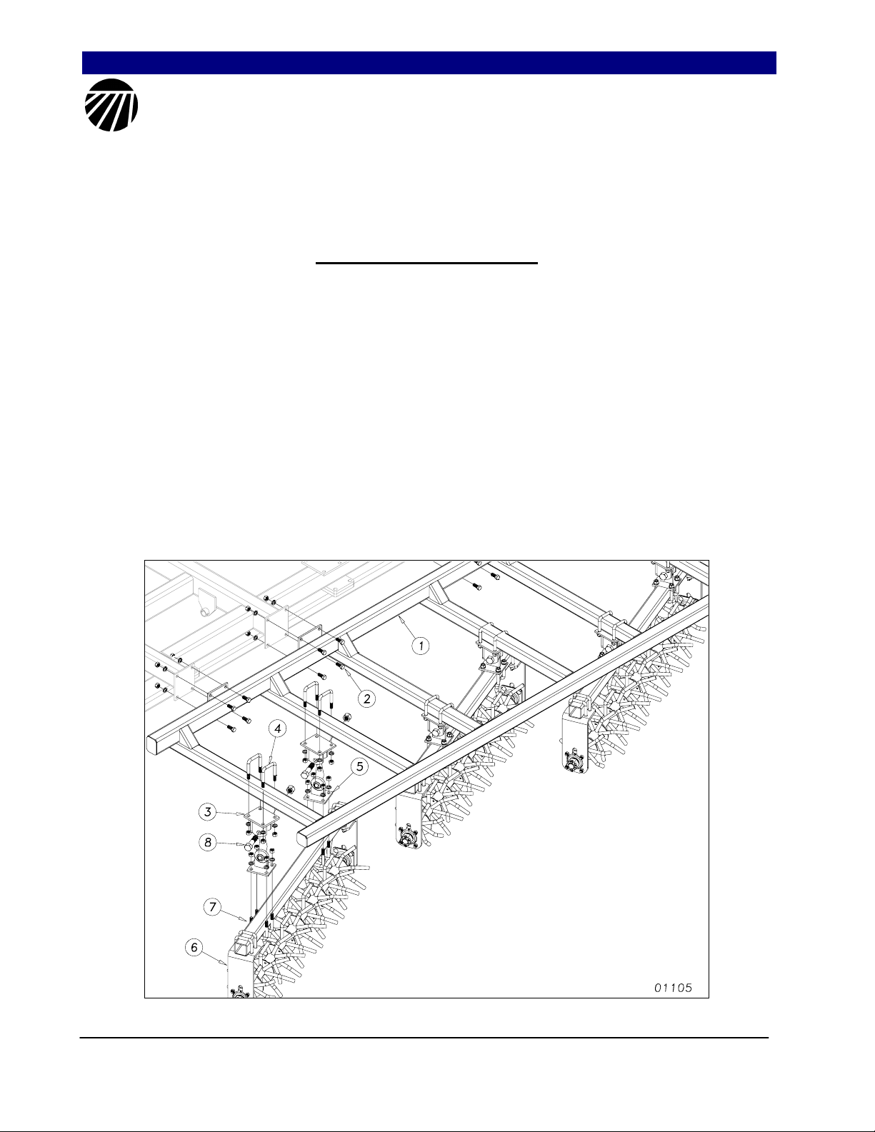
Rolling Harrow Assembly
Your initial action is to bolt the drag
frame (1) to the rear drag plates located on the
rear of your Turbo Till as shown in Figure 1,
using 5/8 x 1 1/2 hex bolts (2) and secure with
lock washer and hex nut.
The rolling harrow gangs will come
pre- assembled. Mount the rolling harrow
mount brackets (3) to the under side of the drag
frames according to the dimensions in the
layout drawings starting on page 6, using 5/8 x
3 x 4 1/2 u-bolts (4) with a lock washer and
nut. You may tighten the u-bolts on all the
brackets. Attach the ball joint bracket (5) to the
rolling harrow assembly (6) using 5/8 x 3 x 4
1/2 u-bolts (7) with a lock washer and hex nut.
You may tighten the right bracket u-bolts, but
leave the left bracket u-bolts loose until the
rolling harrow assemblies are hung under the
frame. Now you may attach the rolling harrow
assembly (6) to the drag frame (1) using a 1x 4
hex bolt (8) using a nylon lock nut. Be careful
to put the proper gang in the proper location
and be sure that the assemblies are positioned
correctly as shown in the layout drawings
stating on page 16. When all gangs are hung
under the frame and positioned in the correct
location, tighten the remaining u-bolts.
Figure 1
SeriesII 1200TT-4000TT Turbo-Till Attachments 586-216M 10/25/2007
4
Page 7
Great Plains Mfg., Inc. Section 2: Assembly & Set-Up
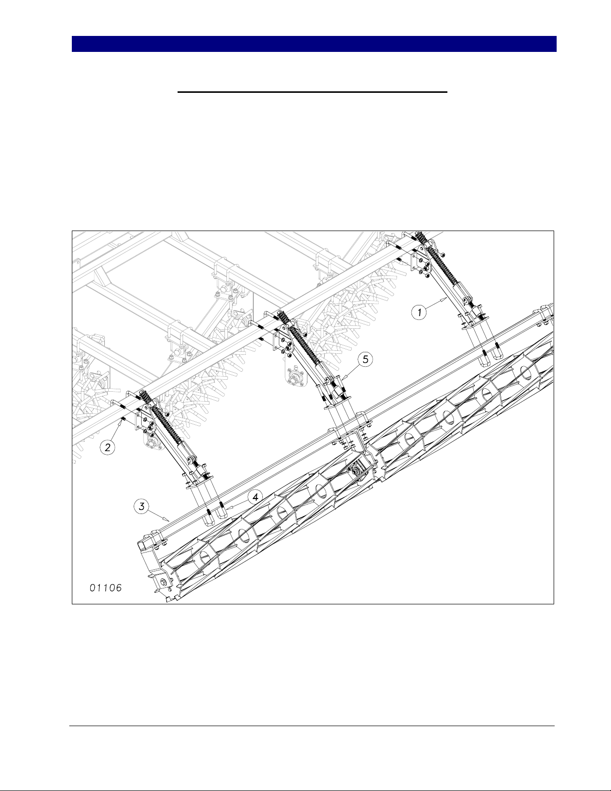
Reel Following the Rolling Harrow Assembly
Mount the reel arm assemblies (1) to the
drag frames as shown in Figure 2, using the
dimensions in the layout drawings starting on
page 7, using a 5/8 x 3 x 4 1/2 u-bolt (2) with a
lock washer and hex nut. These bolts may be
tightened at this time.
Assemble the reel sub-assemblies (3) to
the reel arm assemblies (1) with 5/8 x 2 1/2 x 3
3/4 u-bolt (4), lock washer, and hex nut The
correct reel placement are shown in the
placement drawings, starting on page 16. If
you are assembling a 10’ or 12’ reel, you will
use 5/8 x 4 hex bolts (5), with lock washers and
hex nuts in center location as shown in figure 2.
If the reels between the center section and the
wing sections are closer than 5”, recheck the
reel arm dimensions and adjust accordingly.
Figure 2
10/25/2007 SeriesII 1200TT-4000TT Turbo-Till Attachments 586-216M
5
Page 8
Section 2: Assembly & Set-Up Great Plains Mfg., Inc.
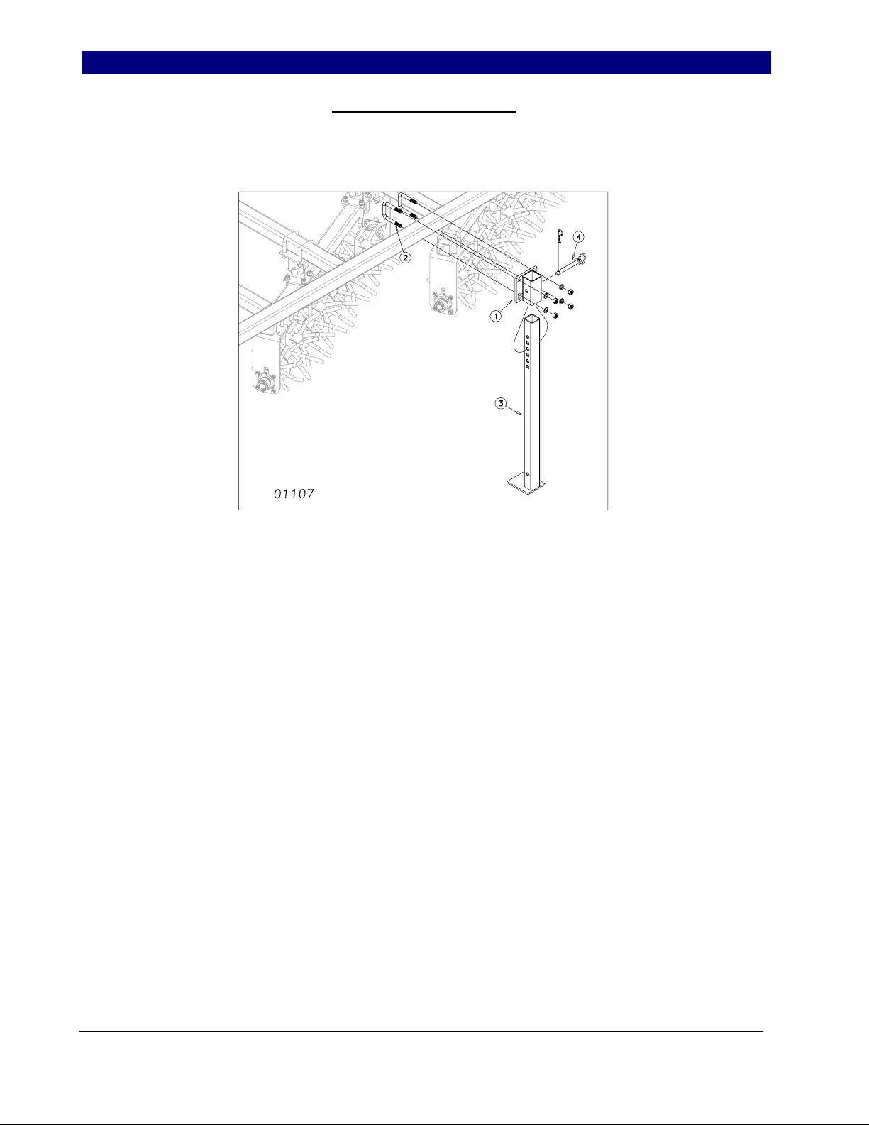
Rear Stand Assembly
Mount the rear stand bracket (1)
Figure 3, if applicable, to the drag frame
using 5/8 x 3 x 4 1/2 u-bolts, lock washer and
hex nut. The rear stand leg (3) should be
pinned in the rear stand bracket (1) using a
3/4 x 4 1/2 pin (4) and retainer.
Figure 3
SeriesII 1200TT-4000TT Turbo-Till Attachments 586-216M 10/25/2007
6
Page 9

Great Plains Mfg., Inc. Section 2: Assembly & Set-Up
This page intentionally left blank.
10/25/2007 SeriesII 1200TT-4000TT Turbo-Till Attachments 586-216M
7
Page 10
Section 3: Operating Instructions Great Plains Mfg., Inc.
Operating Instructions
Prior to Going to the Field
1. Both dealer and customer read and
thoroughly understand all safety
recommendations. (These are found in the
Safety Section of this operator manual.)
2. Make sure your tractor horsepower matches
the implement you are pulling. This is
important so the implement can do the best
possible job.
3. Clean all hydraulic couplings and connect to
tractor or host implement. Each hydraulic
coupling has a colored handle on it and is
marked with a cylinder, either extending or
retracting.
4. After the turbo-till is attached, raise and lower
the turbo-till several times to purge air from
the hydraulic system. Again check for
hydraulic leaks and tighten or replace if
necessary.
5. Check the tire pressure for proper inflation
and check the tightness of the lug bolts. Tire
pressure information can be found in the
Appendix of this manual.
6. Check for any bolts that may need tightened
or retightened. Grease all the hinge points.
The hubs come pre-greased and will not need
more grease at this time.
7. Prior to transporting, fully raise the turbo-till.
Install the transport locks. Always use the
transport locks when moving from field to field
in case of a hydraulic hose failure. You are
now ready to go to the field.
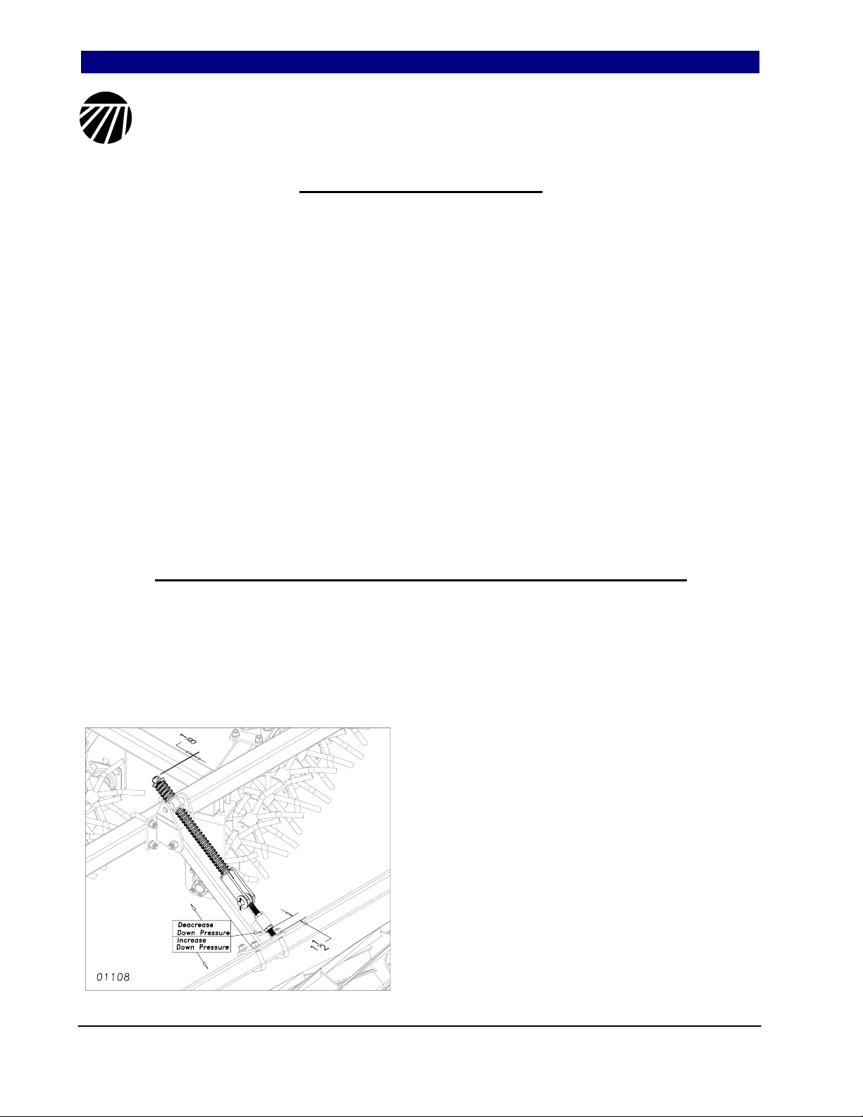
General Operating Instructions and In-Field Adjustments
1. Extend the turbo-till lift cylinders and remove
the transport locks.
2. For an initial starting point, set the pre-load on
the top nut on the reel arm assembly to 1/8”
from the top of the spring bolt to the top of the
3/4” lock nut.
3. Set the pre-load on the eye bolt to 1 1/2” from
the bottom of the eyebolt to the bottom of the
3/4 jam nut, this is also just an initial starting
point
4. You may need to adjust the eyebolt to change
the down pressure. Adjust the bottom 3/4 jam
nut closer to the bottom of the eyebolt for
more down pressure. You may need to adjust
the top lock nut spacing accordingly to raise
reel up for road clearance. Adjust the bottom
3/4 jam nut away from the bottom of the
eyebolt for less down pressure.
SeriesII 1200TT-4000TT Turbo-Till Attachments 586-216M 10/25/2007
8
Page 11
Great Plains Mfg., Inc. Section 4: Maintenamce & Lubrication
Maintenance & Lubrication
1. Always use the transport lock when
working or doing maintenance on the
turbo-till. Read and understand all safety
decals on your equipment.
2. During the first season of operation, and
periodically after that, check your bolts for
tightness.
3. Check wheel bearings occasionally for
excessive endplay.
4. Replace or rotate worn parts as needed—
bolts, clevis pins, bearings, chisel points
etc...
5. Check and tighten or replace any
hydraulic leaks. Check hoses for any
leaks. It is important that there are no
leaks on the equipment.
6. Grease reel bearings and wheel bearings
sparingly. Over greasing may cause
damage to seals and reduce the life of the
bearing. Grease hinge points periodically.
7. Check the rubber spacers occasionally
located next to bearing flange and replace
if badly worn.
8. If machine is stored outdoors over the winter
months it is a good idea to retract the
cylinders to protect the cylinder rods. This
will extend the life of the cylinder seals and
reduce internal and external leaks.
By following and maintaining a routine service and
lubrication program, your tillage attachment will
give you many years of service.
For more information on operating, adjusting
or maintaining your Great Plains Turbo-Till
Attachment contact your local Great Plains
dealer or call
Great Plains Mfg. at (800) 225-9215
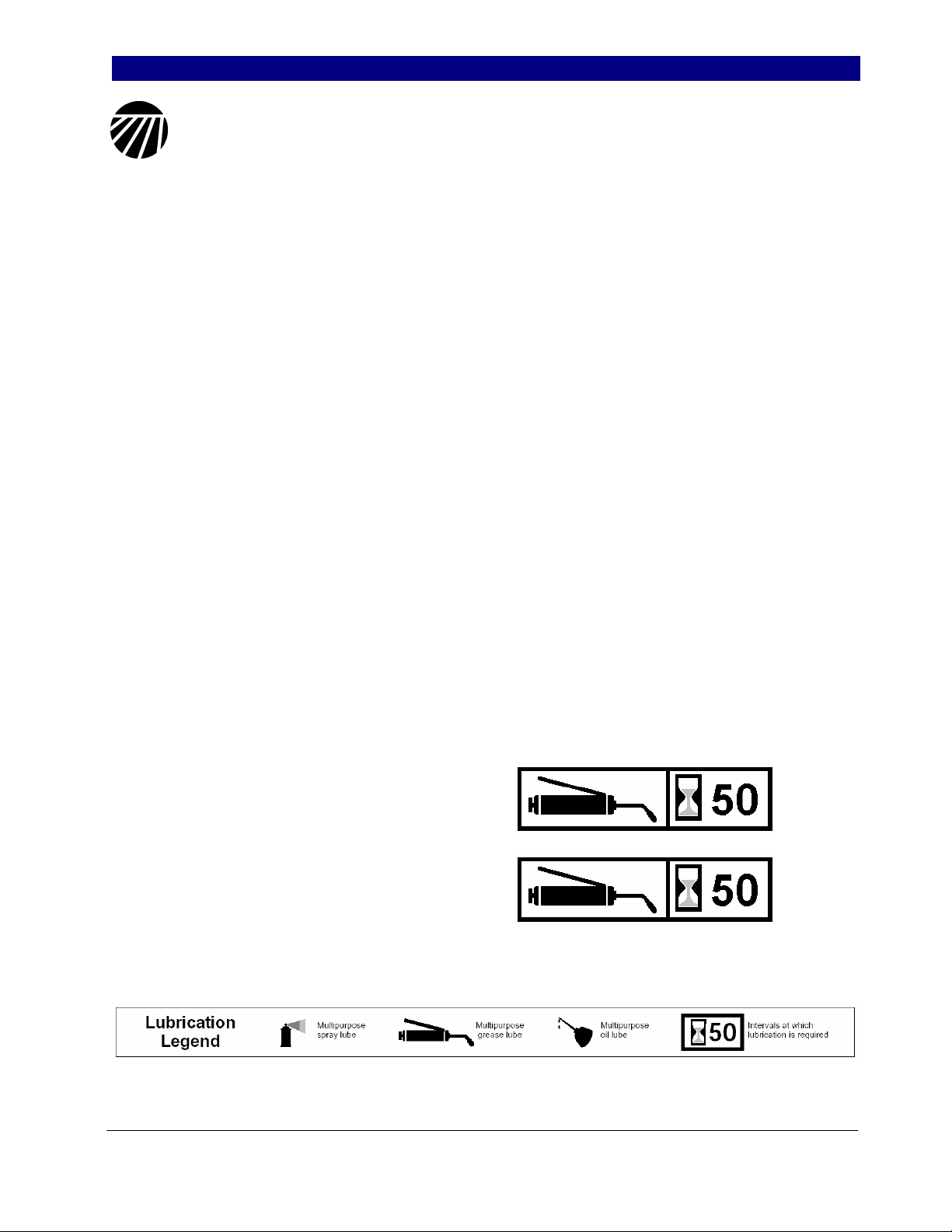
Reel Bearings
Grease every 50 hours (sparingly).
Wheel Bearings
Grease every 50 hours (sparingly) and
check for endplay.
10/25/2007 SeriesII 1200TT-4000TT Turbo-Till Attachments 586-216M
9
Page 12

Section 5: Parts Great Plains Mfg., Inc.
Rolling Harrow Assembly
01104
SeriesII 1200TT-4000TT Turbo-Till Attachments 586-216M 2/4/2009
10
Page 13

Great Plains Mfg., Inc. Section 5: Parts
Rolling Harrow Assembly
Ref. Part No. Part Description Comments
1. 589-111H DRAG FRAME 129 2400TT, 3000TT - Center
589-112H DRAG FRAME 149 1200TT, 4000TT – Center
589-321H DRAG FRAME 189 1500TT
589-348H DRAG FRAME 99 1800TT-Center
589-350H DRAG FRAME 48 1/2 RH 1800TT-Wing
589-349H DRAG FRAME 48 1/2 LH 1800TT-Wing
589-107H DRAG FRAME RH 43 3/4 4000TT - Outside Wing
589-113H DRAG FRAME LH 43 3/4 4000TT - Outside Wing
589-322H DRAG FRAME RH 66 2400TT - Wing
589-323H DRAG FRAME LH 66 2400TT - Wing
589-109H DRAG FRAME RH 106 3000TT - Wing
589-115H DRAG FRAME LH 106 3000TT - Wing
589-110H DRAG FRAME RH 109 1/2 4000TT - Inside Wing
589-116H DRAG FRAME LH 109 1/2 4000TT - Inside Wing
2. 589-220H BRACKET - ROLLING HARROW LH
3. 589-064H BALL JOINT BRACKET
4. 578-001D ROLLING SPIKE TUBE (52) Tube for 8 Wheel Gang
578-002D ROLLING SPIKE TUBE (58) Tube for 9 Wheel Gang
578-003D ROLLING SPIKE TUBE (64) Tube for 10 Wheel Gang
578-004D ROLLING SPIKE TUBE (70) Tube for 11 Wheel Gang
578-005D ROLLING SPIKE TUBE (76) Tube for 12 Wheel Gang
578-006D ROLLING SPIKE TUBE (82) Tube for 13 Wheel Gang
5. 578-011D ROLLING SPIKE BOLT (56 1/ 4) Shaft for 8 Wheel Gang
578-012D ROLLING SPIKE BOLT (62 1/4) Shaft for 9 Wheel Gang
578-013D ROLLING SPIKE BOLT (68 1/4) Shaft for 10 Wheel Gang
578-014D ROLLING SPIKE BOLT (74 1/4) Shaft for 11 Wheel Gang
578-015D ROLLING SPIKE BOLT (80 1/4) Shaft for 12 Wheel Gang
578-016D ROLLING SPIKE BOLT (86 1/4) Shaft for 13 Wheel Gang
6. 589-257H BEARING HANGER (LONG)
7. 589-251H SPIKE WHEEL SMALL
8. 589-258H SPIDER WHEEL LARGE
9. 890-860C SPIDER WHEEL F RONT SPACER
10. 890-861C SPIDER WHEEL REAR SPACER
11. 802-073C HHCS 1-8X4 GR5
12. 803-038C NUT HEX 1-8 NYLON INSERT PLT
13. 806-183C U-BOLT 5/8-11X3 1/32X4 1/2 SPT
14. 804-022C WASHER LOCK SPRING 5/8 PLT
15. 803-021C NUT HEX 5/8-11 PLT
16. 802-051C HHCS 5/8-11X1 1/2 GR5
17. 803-301C NUT HEX SLOTTED 1 1/2-6 PLT
18. 804-063C W ASHER MACH 2.25 X 1.50 X 10GA
19. 802-106C RHSNB 1/2-13X1 1/2 GR5
20. 803-342C NUT HEX TOP LOCK 1/2-13PLT
21. 802-804C HHCS 1/4- 20X2 3/4 GR8 PLT
22. 804-007C WASHER FLAT 1/4 SAE PLT
23. 803-255C NUT HEX NYLOCK 1/4-20
24. 822-208C BRG FLG 1.50ID 4BOLT SQ
2/4/2009 SeriesII 1200TT-4000TT Turbo-Till Attachments 586-216M
11
Page 14

Section 5: Parts Great Plains Mfg., Inc.
Reel Following Rolling Harrow Assembly
00797
SeriesII 1200TT-4000TT Turbo-Till Attachments 586-216M 2/4/2009
12
Page 15

Great Plains Mfg., Inc. Section 5: Parts
Reel Following Rolling Harrow Assembly
Ref. Part No. Part Description Comments
1. 589-059H MOUNTING BRACKET
2. 589-060H ARM - REEL
3. 575-516H CLEVIS BOLT 3/4 (22 1/4)
4. 575-273D PART - 3 1/2' REEL. Models 4000TT
575-092D PART - 5' REEL Models 1500TT, 1800TT
575-093D PART - 6' REEL Models 1500TT, 2400TT
575-096D o PART - 9' REEL Models 1800TT
575-224D n PART - 8' REEL Changed to 575-096D
575-097D PART - 8' REEL Models 3000TT, 4000TT
575-098D PART - 11' REEL Models 2400TT
575-099D PART - 12' REEL Models 1200TT, 4000TT
5. 575-525H REEL ASSEM BLY (3 1/2') Models 1800TT, 4000TT
575-526H 5' REEL ASSEMBLY Models 1500TT, 1800TT, 3000TT, 4000TT
575-527H 6' REEL ASSEMBLY Models 1200TT, 1500TT, 2400TT, 4000TT
6. 575-521H REEL MOUNTING BRACKET
7. 804-024C WASHER F LAT 3/4 USS PLT
8. 807-225C SPRG COMP 1 3/4ODX5/16W X11 1/2
9. 807-226C SPRNG COM 1 13/16OD X3/8WX2 3/4
10. 803-026C NUT LOCK 3/4-10 PLT
11. 802-768C EYE BOLT 3/4-10X6 1/2 PLT
12. 803-048C NUT HEX JAM 3/4-10 PLT
13. 802-192C HHCS 3/4-10X4 1/2 GR5
14. 589-102D REPLACEABLE SWIVEL
15. 802-767C SHOULDER BOLT 5/8-11X1 3/4 SPL
16. 589-252V REPLACEABLE SWIVEL W/BOLTS Includes items 14 & 15
17. 802-066C REEL BEARING SPACER
18. 575-141D REEL BEARING SPACER
19. 804-023C WASHER LOCK SPRING 3/4 PLT
20. 805-140C PIN CLEVIS 3/4 X 2 1/2 PLT
21. 805-225C PIN COTTER 1/8 X 1 1/2
22. 806-183C U-BOLT 5/8-11X3 1/32X4 1/2 SPT
23. 806-182C U-BOLT 5/8-11X2 17/32X3 1/2
24. 802-060C HHCS 5/8-11X4 GR5
25. 804-022C WASHER LOCK SPRING 5/8 PLT
26. 803-021C NUT HEX 5/8-11 PLT
27. 802-128C HHCS 1/2-13X2 GR5
28. 816-429C WASHER RBR 1 3/8ODX9/16IDX1/2L
29. 804-017C WASHER F LAT 1/2 USS PLT
30. 589-085D ZERK GUARD ROLLING HARROW
31. 803-342C NUT HEX TOP LOCK 1/2-13PLT
32. 822-208C BRG FLG 1.50ID 4BOLT SQ
Legend: n = 1st revision; o = 2nd revision, p = 3rd revision; z use up existing stock; ⊗ not interchangeable; ⊗coRevision 2 is not interchangeable with 1
2/4/2009 SeriesII 1200TT-4000TT Turbo-Till Attachments 586-216M
13
Page 16

Section 5: Parts Great Plains Mfg., Inc.
Rear Jack Stand
00798
SeriesII 1200TT-4000TT Turbo-Till Attachments 586-216M 2/4/2009
14
Page 17

Great Plains Mfg., Inc. Section 5: Parts
Rear Jack Stand
Ref. Part No. Part Description Comments
1. 560-196H REAR STAND LEG
2. 580-049H REAR STAND MOUNT BRACKET
3. 806-183C U-Bolt, 5/8-11 x 3 1/32 x 4 1/2 Special
4. 804-022C U-BOLT 5/8-11X3 1/32X4 1/2 SPT
5. 803-021C NUT HEX 5/8-11 PLT
6. 805-195C PIN HITCH 3/4 X 5 1/4 USEABLE
7. 805-032C PIN HAIR COTTER .148 WIRE
2/4/2009 SeriesII 1200TT-4000TT Turbo-Till Attachments 586-216M
15
Page 18

Section 6: Machine Layout Great Plains Mfg., Inc.
12000TT Rolling Harrow
01086
SeriesII 1200TT-4000TT Turbo-Till Attachments 586-216M 10/25/2007
16
Page 19

Great Plains Mfg., Inc. Section 6: Machine Layout
1200TT Reel following Rolling Harrow
01087
10/25/2007 SeriesII 1200TT-4000TT Turbo-Till Attachments 586-216M
17
Page 20

Section 6: Machine Layout Great Plains Mfg., Inc.
15000TT Rolling Harrow
01088
SeriesII 1200TT-4000TT Turbo-Till Attachments 586-216M 10/25/2007
04/16/2008
18
Page 21

Great Plains Mfg., Inc. Section 6: Machine Layout
1500TT Reel following Rolling Harrow
01089
10/25/2007 SeriesII 1200TT-4000TT Turbo-Till Attachments 586-216M
04/16/2008
19
Page 22

Section 6: Machine Layout Great Plains Mfg., Inc.
18000TT Rolling Harrow
01090
SeriesII 1200TT-4000TT Turbo-Till Attachments 586-216M 10/25/2007
04/16/2008
20
Page 23

Great Plains Mfg., Inc. Section 6: Machine Layout
1800TT Reel following Rolling Harrow
01091
10/25/2007 SeriesII 1200TT-4000TT Turbo-Till Attachments 586-216M
2/4/2009
21
Page 24

Section 6: Machine Layout Great Plains Mfg., Inc.
24000TT Rolling Harrow
01092
SeriesII 1200TT-4000TT Turbo-Till Attachments 586-216M 10/25/2007
04/16/2008
22
Page 25

Great Plains Mfg., Inc. Section 6: Machine Layout
2400TT Reel following Rolling Harrow
01093
10/25/2007 SeriesII 1200TT-4000TT Turbo-Till Attachments 586-216M
04/16/2008
23
Page 26
Section 6: Machine Layout Great Plains Mfg., Inc.
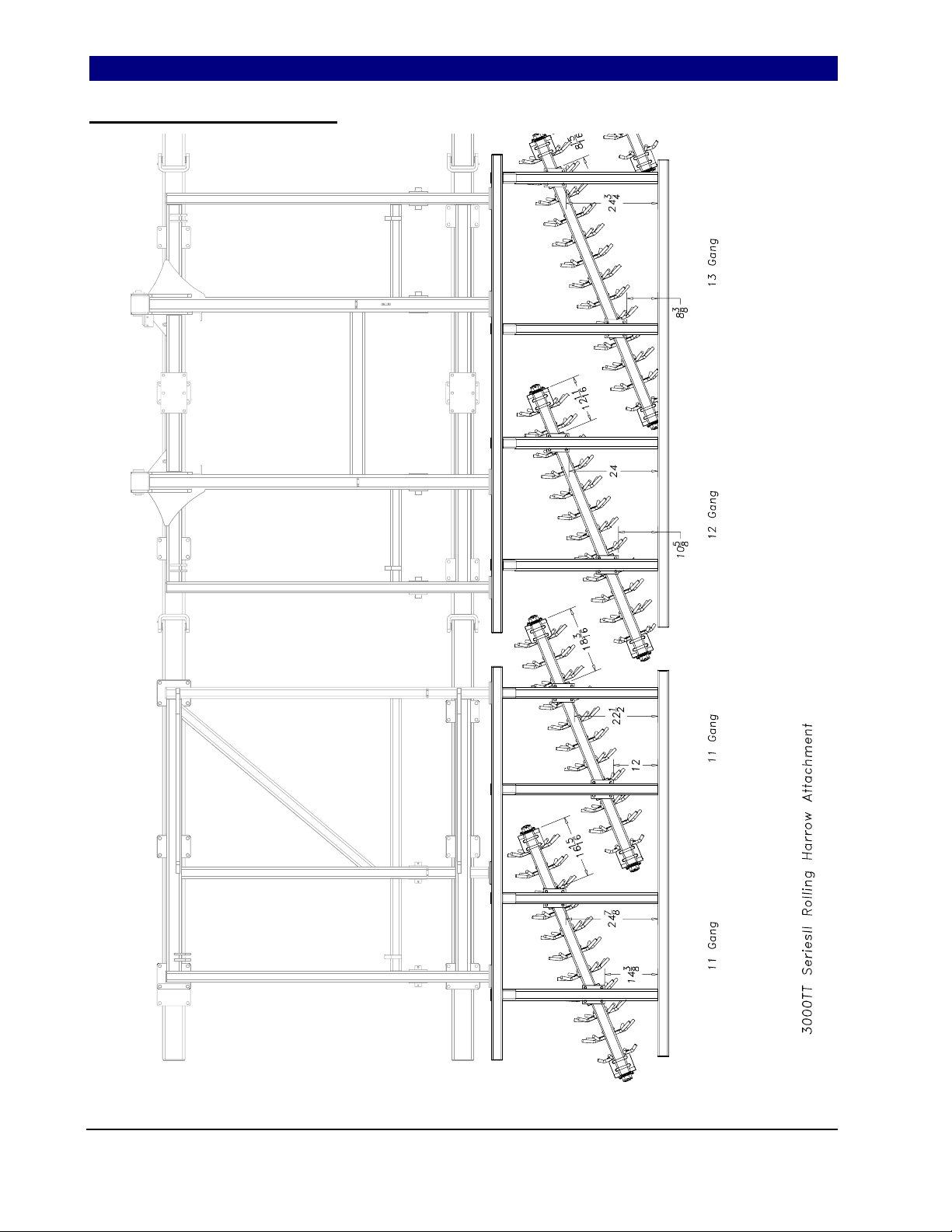
30000TT Rolling Harrow
01094
SeriesII 1200TT-4000TT Turbo-Till Attachments 586-216M 10/25/2007
04/16/2008
24
Page 27

Great Plains Mfg., Inc. Section 6: Machine Layout
30000TT Rolling Harrow
01095
10/25/2007 SeriesII 1200TT-4000TT Turbo-Till Attachments 586-216M
04/16/2008
25
Page 28

Section 6: Machine Layout Great Plains Mfg., Inc.
3000TT Reel following Rolling Harrow
01096
SeriesII 1200TT-4000TT Turbo-Till Attachments 586-216M 10/25/2007
04/16/2008
26
Page 29

Great Plains Mfg., Inc. Section 6: Machine Layout
3000TT Reel following Rolling Harrow
01097
10/25/2007 SeriesII 1200TT-4000TT Turbo-Till Attachments 586-216M
04/16/2008
27
Page 30

Section 6: Machine Layout Great Plains Mfg., Inc.
4000TT Rolling Harrow
01098
SeriesII 1200TT-4000TT Turbo-Till Attachments 586-216M 10/25/2007
28
Page 31

Great Plains Mfg., Inc. Section 6: Machine Layout
40000TT Rolling Harrow
01099
10/25/2007 SeriesII 1200TT-4000TT Turbo-Till Attachments 586-216M
29
Page 32

Section 6: Machine Layout Great Plains Mfg., Inc.
4000TT Reel following Rolling Harrow
01102
SeriesII 1200TT-4000TT Turbo-Till Attachments 586-216M 10/25/2007
30
Page 33

Great Plains Mfg., Inc. Section 6: Machine Layout
4000TT Reel following Rolling Harrow
01103
10/25/2007 SeriesII 1200TT-4000TT Turbo-Till Attachments 586-216M
31
Page 34

Appendix Great Plains Mfg., Inc.
Appendix
Torq ue Values C hart for Co mmon Bolt Size s
Bolt Head Id en tifica tion Bolt Head Identification
Bolt Size
(inches)
¹
in-tpi
1/4" - 20 7.4 5.6 11 8 16 12 M 5 X 0.8 4 3 6 5 9 7
1/4" - 28 8.5 6 13 10 18 14 M 6 X 1 7 5 11 8 15 11
5/16" - 18 15 11 24 17 33 25 M 8 X 1.25 17 12 26 19 36 27
5/16" - 24 17 13 26 19 37 27 M 8 X 1 18 13 28 21 39 29
3/8" - 16 27 20 42 31 59 44 M10 X 1.5 33 24 52 39 72 53
3/8" - 24 31 22 47 35 67 49 M10 X 0.75 39 29 61 45 85 62
7/16" - 14 43 32 67 49 95 70 M12 X 1.75 58 42 91 67 125 93
7/16" - 20 49 36 75 55 105 78 M12 X 1.5 60 44 95 70 130 97
1/2" - 13 66 49 105 76 145 105 M12 X 1 90 66 105 77 145 105
1/2" - 20 75 55 115 85 165 120 M14 X 2 92 68 145 105 200 150
9/16" - 12 95 70 150 110 210 155 M14 X 1.5 99 73 155 115 215 160
9/16" - 18 105 79 165 120 235 170 M16 X 2 145 105 225 165 315 230
5/8" - 11 130 97 205 150 285 210 M16 X 1.5 155 115 240 180 335 245
5/8" - 18 150 110 230 170 325 240 M18 X 2.5 195 145 310 230 405 300
3/4" - 10 235 170 360 265 510 375 M18 X 1.5 220 165 350 260 485 355
3/4" - 16 260 190 405 295 570 420 M20 X 2.5 280 205 440 325 610 450
7/8" - 9 225 165 585 430 820 605 M20 X 1.5 310 230 650 480 900 665
7/8" - 14 250 185 640 475 905 670 M24 X 3 480 355 760 560 1050 780
1" - 8 340 250 875 645 1230 910 M24 X 2 525 390 830 610 1150 845
1" - 12 370 275 955 705 1350 995 M30 X 3.5 960 705 1510 1120 2100 1550
1-1/8" - 7 480 355 1080 795 1750 1290 M30 X 2 1060 785 1680 1240 2320 1710
1 1/8" - 12 540 395 1210 890 1960 1440 M36 X 3.5 1730 1270 2650 1950 3660 2700
1 1/4" - 7 680 500 1520 1120 2460 1820 M36 X 2 1880 1380 2960 2190 4100 3220
1 1/4" - 12 750 555 1680 1240 2730 2010
1 3/8" - 6 890 655 1990 1470 3230 2380
1 3/8" - 12 1010 745 2270 1670 3680 2710
1 1/2" - 6 1180 870 2640 1950 4290 3160
1 1/2" - 12 1330 980 2970 2190 4820 3560
Gang Bolt Torque 1 1/2”-6 700 Foot-pounds (175 lbs on 4’ cheater).
N · m²ft-lb
Torque tolerance + 0%, -15% of torquing v alues. U nless othe rwise specified use torque values listed above.
³
N · m ft-lb N · m ft-lb mm x pitch N · m ft-lb N · m ft-lb N · m ft-lb
Bolt Size
(metric)
4
¹ in-tpi = nominal thread diameter in inches-threads per inch
² N· m = newton-meters
4
mm x pitch = nominal thread diameter in millimeters x thread pitch
³ ft-lb= foot pounds
Class 10.9Grade 2 Grade 5 Grade 8 Class 5.8 Class 8.8
Tire Inflation Chart
Inflation
Tire Size
11L x 15" 8-Ply Rib Implement 36 395/55B 16.5 NHS Skid Steer 60
11L x 15" 12-Ply Rib Implement 52 12.5L x 16.5 Load G (Galaxy) 105
11L x 15" F-Ply Rib Implement 90 32-15.5 x 16.5 Load G (Galaxy) 105
12.5L x 15" F-Ply Rib Implement 90 400/60-15.5 Trelleborg Twin 404 29-51
PSI
Tire Size
SeriesII 1200TT-4000TT Turbo-Till Attachments 586-216M 10/25/2007
Inflation
PSI
32
Page 35

Great Plains Manufacturing, Inc.
Corporate Office: PO. Box 5060
Salina, Kansas 67402-5060 USA
 Loading...