

Page 1
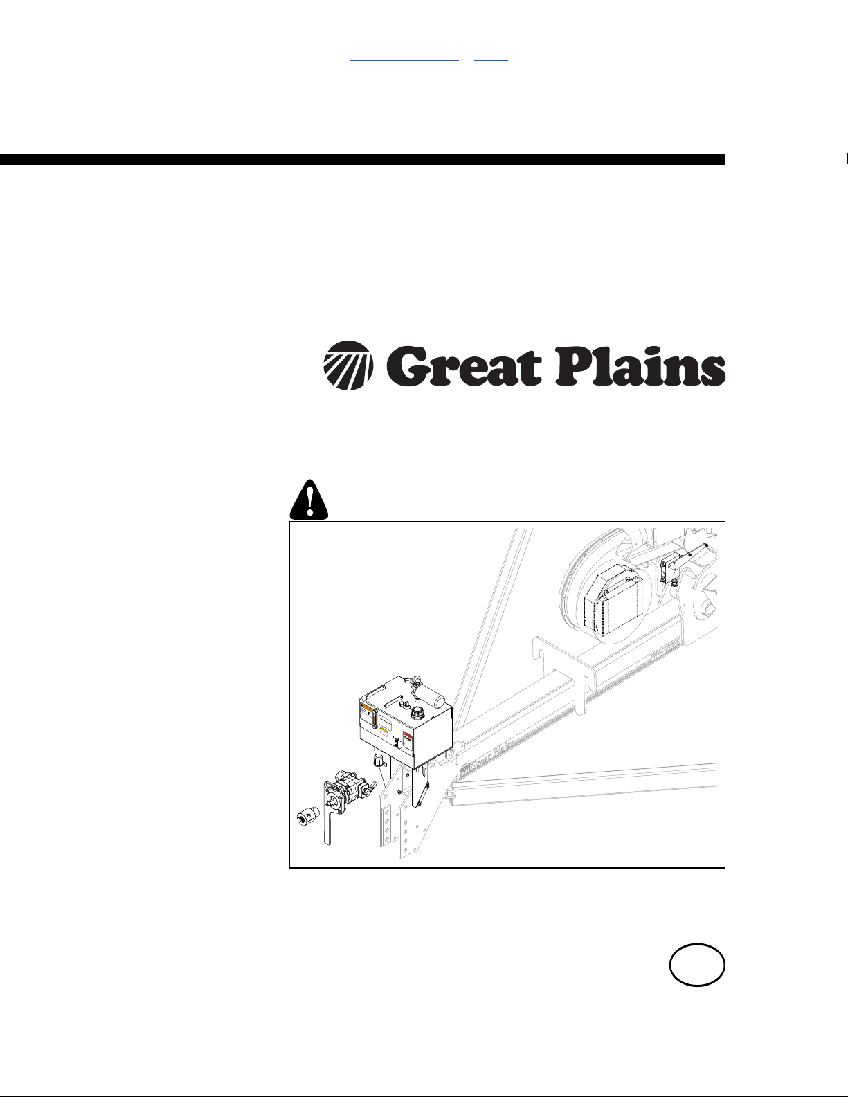
Table of Contents Index
Operating, Maintenance
and Installation Instructions
PTO Pump Accessory for 2- & 3-Section Yield-Pro® Planters
Kits: 401-934A 401-935A 401-936A 401-937A 401-938A
401-939A 401-940A 401-941A 401-942A 401-943A 401-944A
401-945A 401-946A 401-951A 411-014A 411-138A 411-147A
Manufacturing, Inc.
www.greatplainsmfg.com
Read the installation manual entirely. When you see this symbol, the
subsequent instructions and warnings are serious - follow without exception.
Your life and the lives of others depend on it!
WARNING
HOT FLUID HAZARD
Read Owner’s Manual BEFORE operating machine.
Keep tractor at IDLING SPEED and slowly engage PTO
to prevent damage to Hydraulic Motor
Keep Radiator clean and free of foreign matter to
prevent overheating.
OIL FILL LINE
Do NOT operate with hydraulic oil at or above 180°F.
CAPACITY = 13.5 U.S. GALS
USE ANY HIGH QUALITY MINERAL BASED
HYDRAULIC FLUID WITH A VISCOSITY RATING
OF 10W-30. OIL MUST BE CLEAN AND FREE
FROM DIRT OR CONTAMINANT PARTICLES TO
PREVENT DAMAGE TO PUMP AND MOTOR.
REPLACE FILTER ELEMENT AFTER EVERY
858-004C
150 OPERATING HOURS OR 2 YEARS SERVICE.
LEVEL TOOLBAR BEFORE CHEKING OIL
CAUTION
To avoid Injury or
LEVEL
858-029C
Machine Damage:
·Operate only with
1000 rpm PTO
DANGER
818-240C Rev. A
ROTATING DRIVELINE -
CONTACT CAN CAUSE DEATH
KEEP AWAY!
DO NOT OPERATE WITHOUT-
All driveline guards, tractor
and equipment shields in place
PTO pump assembly securely
attached with torque arm and clamp
bolts properly torqued
858-030C
34843
Cover illustration shows only selected components for one kit, and the coupler, which is
ordered separately. Manual illustrations may show various Yield-Pro
®
planter models
and configurations where installation details are identical for the immediate topic.
ORIGINAL INSTRUCTIONS
EN
© Copyright 2014 Printed 2014-09-10 411-015M
Table of Contents Index
Page 2

PTO Pump Table of Contents Index
Table of Contents Index
Page 3

Great Plains Manufacturing, Inc. Cover Index iii
Table of Contents
Important Safety Information ...................................... 1
PTO-Specific Hazards....................................................1
Using PTO Safely...........................................................2
Safety Decals ................................................................. 4
Introduction ..................................................................6
Description of Unit ..........................................................6
Kits Covered...................................................................6
Suitable Applications ..................................................6
Related Items ................................................................. 6
PTO Coupler...........................................................6
Hydraulic Tongue Extension...................................6
Compressor Relocation Kits ...................................6
Using This Manual..........................................................7
Definitions................................................................... 7
Call-Outs ....................................................................7
Owner Assistance ..........................................................7
PTO Operation ..............................................................8
Tractor Requirements.....................................................8
Type 2 PTO Clearance...........................................8
1000 rpm Type 3 PTO Clearance...........................9
Install Coupler ................................................................9
Hitching with PTO.........................................................10
Prepare Tractor ........................................................10
Mount and Pump ......................................................10
Check Hydraulics .........................................................11
Check Oil Level ........................................................11
Inspect Hoses and Fittings .......................................11
Starting the Pump.........................................................12
About the Flow Control Valve.......................................12
Flow Control Page Reference ..................................13
Flow Adjust: Hydraulic Drive Center-Fill IntelliAg
®
Air-Pro® Planters .............................................. 14
Flow Adjust: Ground Drive IntelliAg® Center-Fill
Planters ............................................................ 15
Flow Adjust: Ground Drive Row-Hopper Air-Pro
®
(Meter-Only) Planters ....................................... 16
Flow: Ground Drive Row-Hopper Air-Pro® Dry
Fertilizer Planters ............................................. 17
Flow Adjust: Hydraulic Drive IntelliAg
®
Singulator Plus™ & Finger Pick-Up Planters ... 18
Flow: Ground Drive Row Hopper Finger Pick-Up &
Brush Meter Planters........................................ 19
PTO Unhitching............................................................ 20
PTO Troubleshooting ................................................ 21
PTO Maintenance....................................................... 22
Oil and Filter Change ................................................... 22
Oil Fill ....................................................................... 22
Oil Specification ................................................... 22
Oil and Filter Change ............................................... 22
Lubrication and Scheduled Maintenance..................... 23
Appendix A - Installation........................................... 24
Compatible Planters..................................................... 25
Install First or Only Compressor............................... 41
Second Compressor, 1625AH, YP12/16.................. 42
Second Compressor, YP24/30/40/44....................... 42
Hydraulic Hitch Extension ........................................ 49
Appendix R - Reference ............................................ 85
Torque Values.............................................................. 85
Hydraulic Fitting Torque ........................................... 86
Connector Identification ....................................... 86
Abbreviations ............................................................... 87
Parts............................................................................. 88
Index............................................................................ 91
© Copyright 2013, 2014 All rights Reserved
Great Plains Manufacturing, Inc. provides this publication “as is” without warranty of any kind, either expressed or implied. While every precaution has been
taken in the preparation of this manual, Great Plains Manufacturing, Inc. assumes no responsibility for errors or omissions. Neither is any liability assumed for
damages resulting from the use of the information contained herein. Great Plains Manufacturing, Inc. reserves the right to revise and improve its products as
it sees fit. This publication describes the state of this product at the time of its publication, and may not reflect the product in the future.
2014-09-10 Cover Index 411-015M
Trademarks of Great Plains Manufacturing, Inc. include: Singulator Plus, Swath Command, Terra-Tine.
Registered Trademarks of Great Plains Manufacturing, Inc. include:
Air-Pro, Clear-Shot, Discovator, Great Plains, Land Pride, MeterCone, Nutri-Pro, Seed-Lok, Solid Stand,
Terra-Guard, Turbo-Chisel, Turbo-Chopper, Turbo Max, Turbo-Till, Ultra-Till, Ver ti-Till, Whirlfilter, Yield-Pro.
Brand and Product Names that appear and are owned by others are trademarks of their respective owners.
Printed in the United States of America
Page 4

iv 2- & 3-Section YP PTO Pumps Table of Contents Index Great Plains Manufacturing, Inc.
411-015M Table of Contents Index 2014-09-10
Page 5
Great Plains Manufacturing, Inc. Table of Contents Index 1
Important Safety Information
PTO-Specific Hazards
Even if you are experienced in PTO operations, review
the “Using PTO Safely” topic on page 2. Topics in this
manual dealing with PTO hazards include this PTO alert
symbol and the standard alert symbol below.
PTO hazards include:
▲ Entanglement:
resulting in abrasions, lacerations, crushing,
dismemberment or death. Loose clothing, cuffs, frays, laces,
coattails, drawstrings, hair or scarves are taken up by a
PTO faster than you can react, and with overpowering
torque.
▲ Flailing machinery:
resulting from an unsecured torque arm, resulting in serious
injury or death.
▲ High pressure fluid sprays:
due to hydraulic hose failure, resulting from PTO shaft
over-speed or damaged hoses.
Look for Safety Symbol
The SAFETY ALERT SYMBOL indicates there is a
potential hazard to personal safety involved and extra
safety precaution must be taken. When you see this
symbol, be alert and carefully read the message that
follows it. In addition to design and configuration of
equipment, hazard control and accident prevention are
dependent upon the awareness, concern, prudence and
proper training of personnel involved in the operation,
transport, maintenance and storage of equipment.
Be Aware of Signal Words
Signal words designate a degree or level of hazard
seriousness.
DANGER indicates an imminently hazardous situation
which, if not avoided, will result in death or serious injury.
This signal word is limited to the most extreme situations,
typically for machine components that, for functional
purposes, cannot be guarded.
WARNING indicates a potentially hazardous situation
which, if not avoided, could result in death or serious
injury, and includes hazards that are exposed when
guards are removed. It may also be used to alert against
unsafe practices.
CAUTION indicates a potentially hazardous situation
which, if not avoided, may result in minor or moderate
injury. It may also be used to alert against unsafe
practices.
2014-09-10 Table of Contents Index 411-015M
Page 6
2 2- & 3-Section YP PTO Pumps Table of Contents Index Great Plains Manufacturing, Inc.
Using PTO Safely
The pump relies on PTO power to operate, and requires
an adjustment at the planter while the PTO is running.
The PTO pump is designed to work on a stub shaft PTO,
leaving no exposed shaft in use.
▲ Use only a tractor with an approved PTO master shield.
▲ Use all guards provide for the tractor PTO. Have minimal
or NO shaft exposed after connecting the PTO pump.
▲ Use only a rear-facing PTO. The provided hoses and torque
arms are not designed for use with a tractor-front or
tractor-side PTO.
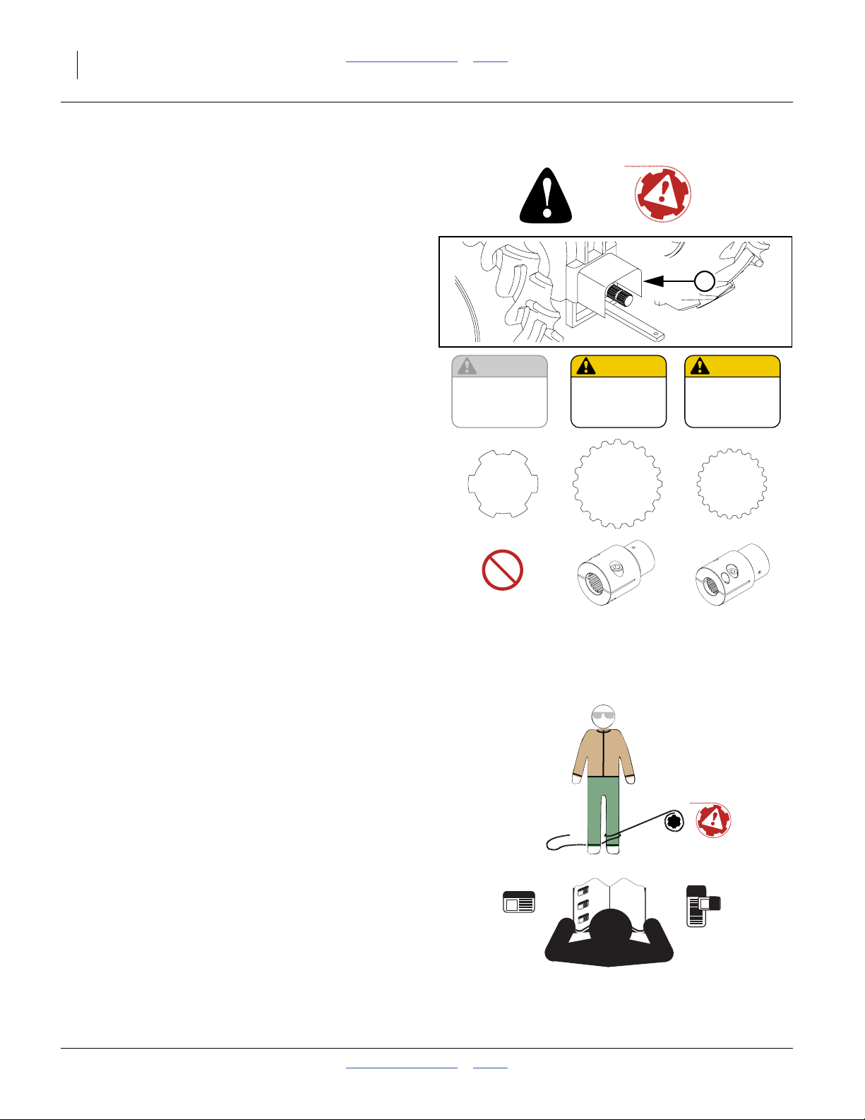
▲ Use only a 1000 rpm PTO, or an adjustable PTO set to
1000 rpm maximum. Running at a higher speed could result
in equipment failure, and serious injury.
▲ Use only a PTO with the correct shaft and matching Great
Plains coupler:
13⁄4inch (44.5 mm) 20-spline and 826-777C coupler
13⁄8inch (35 mm) 21-spline and 826-778C coupler
▲ Do not use any other adaptor, coupler, driveline, extender
or external gearbox.
▲ Use only a “live” or “independent” PTO. If the PTO only
operates when the tractor is in motion, there is no safe way
to set the fan speed.
▲ Ensure that all involved personnel are trained on PTO
operations and hazards. Always know where all team
members are before, during and after PTO operations.
▲ Allow only essential personnel near the PTO during setup,
adjustment, operation and disconnection.
▲ Prior to PTO setup, remove any stray wire, rope or twine
found nearby. Should a loose end encounter the PTO stub, it
is taken up at over 14 feet per second, and could wrap
around someone and pull them in.
▲ Wear only snug-fitting clothes, with no scarves, loose
strings, frays, cords or ties, when working near a PTO. Tie
long hair back or gather it up under a well-secured hat.
▲ Shut the tractor off for PTO connections or disconnections.
Do not trust your life to clutches and throw-outs.
▲ A PTO shaft is a hazard at any speed, even when well below
rated shaft rpm, coasting to a stop, or idling.
▲ Never step on or over the master shield or installed PTO
pump.
▲ Be extra vigilant if any tractor PTO controls are external,
and in proximity to the PTO.
▲ Elevate pump hose slack so that ground contact is not
possible during transport or field operations.
▲ Keep all PTO safety decals clean and legible. Replace any
that are faded or damaged.
CAUTION
To avoid Injury or
Machine Damage:
*Operate only with
540 rpm PTO
818-130C Rev. B
✘
6
CAUTION
To avoid Injury or
Machine Damage:
·Operate only with
1000 rpm PTO
✔
826-777C
818-240C Rev. A
20
✔
CAUTION
To avoid Injury or
Machine Damage:
·Operate only with
1000 rpm PTO
826-778C
818-240C Rev. A
✔
21
411-015M Table of Contents Index 2014-09-10
Page 7

Great Plains Manufacturing, Inc. Table of Contents Index Important Safety Information 3
Prepare for Emergencies
▲ Be prepared if a fire starts
▲ Keep a first aid kit and fire extinguisher handy.
▲ Keep emergency numbers for doctor, ambulance, hospital
and fire department near phone.
Be Familiar with Safety Decals
▲ Read and understand “Safety Decals” in the Operator
manual.
▲ Read all instructions noted on the decals.
▲ Keep decals clean. Replace damaged, faded and illegible
decals.
Protect Hearing
The PTO system requires adjustment of a flow control
valve with one or two implement fans running. The valve
is locate near the fans, and the fans are loud.
▲ Wear hearing protection when working near an operating
hydraulic fan.
Avoid High Pressure Fluids
Observe normal precautions for hitch hydraulic
connections and disconnections. Escaping fluid under
pressure can penetrate the skin, causing serious injury.
▲ Avoid the hazard by relieving pressure before disconnecting
hydraulic lines.
▲ Wear protective gloves and safety glasses or goggles when
working with hydraulic systems.
▲ If an accident occurs, seek immediate medical assistance
from a physician familiar with this type of injury.
Practice Safe Maintenance
▲ Understand procedure before doing work. Use proper
tools and equipment. Refer to this manual for additional
information.
▲ Work in a clean, dry area.
▲ Lower the planter, put tractor in park, turn off engine, and
remove key before performing maintenance.
▲ Make sure all moving parts have stopped and all system
pressure is relieved.
▲ Inspect all parts. Make sure parts are in good condition
and installed properly.
▲ Remove buildup of grease, oil or debris.
▲ Remove all tools and unused parts from planter before
operation.
2014-09-10 Table of Contents Index 411-015M
Page 8
4 2- & 3-Section YP PTO Pumps Table of Contents Index Great Plains Manufacturing, Inc.
Safety At All Times
▲ Thoroughly read and understand the instructions in this
manual before operation. Read all instructions noted on the
safety decals.
▲ Be familiar with all implement functions.
▲ Operate machinery from the driver’s seat only.
▲ Do not leave implement unattended with tractor engine
running.
▲ Wear snug-fitting clothing to avoid entanglement with
moving parts.
Safety Decals
Safety Decals
Kit components are shipped with all safety decals in
place. They are intended to help you safely operate your
implement.
▲ Read and follow decal directions.
▲ Keep all safety decals clean and legible.
▲ Replace all damaged or missing decals. Order new decals
from your Great Plains dealer. Refer to this section for
proper decal placement.
▲ When ordering new parts or components, also request
corresponding safety decals.
To install new decals:
1. Clean the area on which the decal is to be placed.
2. Peel backing from decal. Press firmly on surface,
being careful not to cause air bubbles under decal.
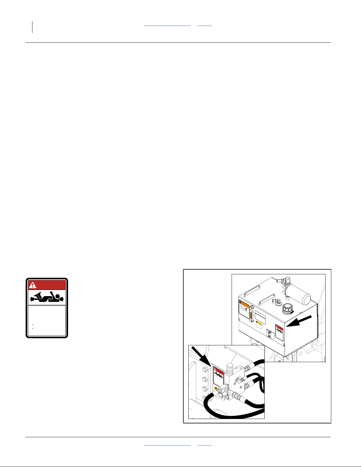
Danger Decals
858-030C
DANGER
ROTATING DRIVELINE -
CONTACT CAN CAUSE DEATH
KEEP AWAY!
DO NOT OPERATE WITHOUT-
All driveline guards, tractor
and equipment shields in place
PTO pump assembly securely
attached with torque arm and clamp
bolts properly torqued
Danger: Rotating Driveline
Pull-Type on front face of oil reservoir,
3PYP/A on valve mount plate;
1 total
858-030C
34843
DANGER
ROTATING DRIVELINE -
CONTACT CAN CAUSE DEATH
KEEP AWAY!
DO NOT OPERATE WITHOUT-
All driveline guards, tractor
and equipment shields in place
PTO pump assembly securely
attached with torque arm and clamp
bolts properly torqued
CAUTION
To avoid Injury or
Machine Damage:
·Operate only with
1000 rpm PTO
34843
WARNING
HOT FLUID HAZARD
Read Owner’s Manual BEFORE operating machine.
Keep tractor at IDLING SPEED and slowly engage PTO
to prevent damage to Hydraulic Motor
Keep Radiator clean and free of foreign matter to
prevent overheating.
OIL FILL LINE
Do NOT operate with hydraulic oil at or above 180°F.
CAPACITY = 13.5 U.S. GALS
USE ANY HIGH QUALITY MINERAL BASED
HYDRAULIC FLUID WITH A VISCOSITY RATING
OF 10W-30. OIL MUST BE CLEAN AND FREE
FROM DIRT OR CONTAMINANT PARTICLES TO
PREVENT DAMAGE TO PUMP AND MOTOR.
REPLACE FILTER ELEMENT AFTER EVERY
858-004C
150 OPERATING HOURS OR 2 YEARS SERVICE.
LEVEL TOOLBAR BEFORE CHEKING OIL LEVEL
CAUTION
To avoid Injury or
858-029C
Machine Damage:
·Operate only with
1000 rpm PTO
858-030C
818-240C Rev. A
DANGER
818-240C Rev. A
ROTATING DRIVELINE -
CONTACT CAN CAUSE DEATH
KEEP AWAY!
DO NOT OPERATE WITHOUT-
All driveline guards, tractor
and equipment shields in place
PTO pump assembly securely
attached with torque arm and clamp
bolts properly torqued
858-030C
411-015M Table of Contents Index 2014-09-10
Page 9
Great Plains Manufacturing, Inc. Table of Contents Index Important Safety Information 5
Warning Decals
858-004C
WARNING
34843
HOT FLUID HAZARD
Read Owner’s Manual BEFORE operating machine.
Keep tractor at IDLING SPEED and slowly engage PTO
to prevent damage to Hydraulic Motor
Keep Radiator clean and free of foreign matter to
prevent overheating.
Do NOT operate with hydraulic oil at or above 180°F.
858-004C
Warning: Hot Fluid
On front face of oil reservoir;
1 total
Caution Decals
818-240C
CAUTION
To avoid Injury or
Machine Damage:
·Operate only with
1000 rpm PTO
Caution: 1000 RPM PTO
Pull-Type on front face of oil reservoir,
3PYP/A on valve mount plate;
1 total
818-240C Rev. A
WARNING
HOT FLUID HAZARD
Read Owner’s Manual BEFORE operating machine.
Keep tractor at IDLING SPEED and slowly engage PTO
to prevent damage to Hydraulic Motor
Keep Radiator clean and free of foreign matter to
prevent overheating.
Do NOT operate with hydraulic oil at or above 180°F.
858-004C
OIL FILL LINE
CAPACITY = 13.5 U.S. GALS
USE ANY HIGH QUALITY MINERAL BASED
HYDRAULIC FLUID WITH A VISCOSITY RATING
OF 10W-30. OIL MUST BE CLEAN AND FREE
FROM DIRT OR CONTAMINANT PARTICLES TO
PREVENT DAMAGE TO PUMP AND MOTOR.
REPLACE FILTER ELEMENT AFTER EVERY
150 OPERATING HOURS OR 2 YEARS SERVICE.
LEVEL TOOLBAR BEFORE CHEKING OIL LEVEL
CAUTION
To avoid Injury or
Machine Damage:
·Operate only with
1000 rpm PTO
818-240C Rev. A
34843
WARNING
HOT FLUID HAZARD
Read Owner’s Manual BEFORE operating machine.
Keep tractor at IDLING SPEED and slowly engage PTO
to prevent damage to Hydraulic Motor
Keep Radiator clean and free of foreign matter to
prevent overheating.
Do NOT operate with hydraulic oil at or above 180°F.
858-029C
DANGER
ROTATING DRIVELINE -
CONTACT CAN CAUSE DEATH
KEEP AWAY!
DO NOT OPERATE WITHOUT-
All driveline guards, tractor
and equipment shields in place
PTO pump assembly securely
attached with torque arm and clamp
bolts properly torqued
858-030C
OIL FILL LINE
CAPACITY = 13.5 U.S. GALS
USE ANY HIGH QUALITY MINERAL BASED
HYDRAULIC FLUID WITH A VISCOSITY RATING
OF 10W-30. OIL MUST BE CLEAN AND FREE
FROM DIRT OR CONTAMINANT PARTICLES TO
PREVENT DAMAGE TO PUMP AND MOTOR.
REPLACE FILTER ELEMENT AFTER EVERY
858-004C
150 OPERATING HOURS OR 2 YEARS SERVICE.
LEVEL TOOLBAR BEFORE CHEKING OIL LEVEL
CAUTION
To avoid Injury or
858-029C
Machine Damage:
·Operate only with
1000 rpm PTO
DANGER
818-240C Rev. A
ROTATING DRIVELINE -
CONTACT CAN CAUSE DEATH
KEEP AWAY!
DO NOT OPERATE WITHOUT-
All driveline guards, tractor
and equipment shields in place
PTO pump assembly securely
attached with torque arm and clamp
bolts properly torqued
858-030C
DANGER
ROTATING DRIVELINE -
CONTACT CAN CAUSE DEATH
KEEP AWAY!
DO NOT OPERATE WITHOUT-
All driveline guards, tractor
and equipment shields in place
PTO pump assembly securely
attached with torque arm and clamp
bolts properly torqued
858-030C
CAUTION
To avoid Injury or
Machine Damage:
·Operate only with
1000 rpm PTO
818-240C Rev. A
34843
2014-09-10 Table of Contents Index 411-015M
Page 10
6 2- & 3-Section YP PTO Pumps Table of Contents Index Great Plains Manufacturing, Inc.
Introduction
Description of Unit
One of 15 dealer- or field-installed kits convert the
planter’s hydraulic motor power source from a tractor
hydraulic remote circuit to tractor Power Take-Off (PTO).
Kits Covered
401-934A YP12,16 HYD DRV PTO KIT
401-935A YP12A,16A HYD DRV PTO KIT
401-936A YP12,16 GRND DRV PTO KIT
401-937A YP12A,16A GRND DRV PTO KIT
401-938A YP16F PTO KIT
401-939A 3PYP HYD DRV PTO KIT
401-940A 3PYPA HYD DRV PTO KIT
401-941A 3PYP GRND DRV PTO KIT
401-942A 3PYPA GRND DRV PTO KIT
401-943A YP24 PTO KIT
401-944A YP24A PTO KIT
401-945A YP30,40 PTO KIT
401-946A YP30A,40A PTO KIT
401-951A YP44A PTO KIT
411-014A YP24F PTO HYDRAULIC PUMP KIT
411-138A YP16AHL PTO KIT
411-147A YP16AHD PTO KIT
U
R
F
B
3
L
D
WARNING
HOT FLUID HAZARD
Read Own
Keep tract
e
r
’
s Manual BEFORE opera
to prevent damage to Hydraulic
or at IDLING
Keep Radiator clean and free of foreign
prevent ov
OIL FILL LINE
SPEED a
Do NOT operate with hydraulic oil
erheati
t
ing machine.
n
d slowly engage PTO
ng.
Motor
CAPACITY = 13.5 U.S. GALS
USE ANY HIGH QUALITY MINERAL BASED
matter t
HYDRAULIC FLUID WIT
at or
OF 10W-3
o
a
bov
FROM DIRT OR CONTAMINANT
e
180
PREVENT DAMAGE TO PUM
0. OIL MUST BE CLEAN AND FREE
°
F.
REPLACE FILTER ELEMENT AFTER EVERY
8
5
8-004C
150 OPERATING HOURS OR 2 YEAR
H A VISCOSITY RATING
LEVEL TOOLBAR BEFORE CHEKING OIL LEVEL
PARTICLES TO
P AND MOTOR.
S SE
R
VICE.
CAUTION
To avoid Injury or
8
5
8
0
2
9C
Machine Damage:
5
·Operate only with
1000 rpm PTO
DANGER
818-240C
Rev. A
ROTATING DRIVELINE -
CONTACT CAN CAUSE DEATH
KEEP AWAY!
DO NOT OPERATE WITHOUT-
All driveline guards, tractor
and equipment shields in place
PTO pump assembly securely
attached with torque
bolts properly torqued
arm and clamp
858-030C
4
2
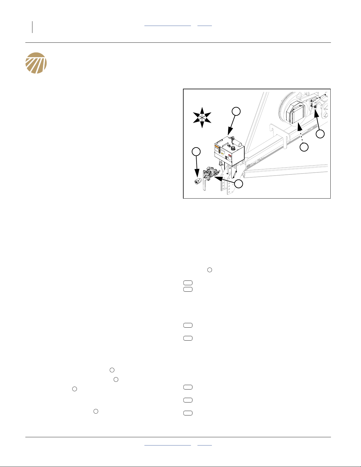
Figure 1:
PTO Kit Major Components
Note: If you are reviewing this manual prior to kit
purchase, see the compatibility table on page 25.
1
34617
There are separate kits covering most Great Plains large
folding Yield-Pro® planters, with separate kits for ground
drive and hydraulic drive seeding.
Kits are not presently available for planters with hydraulic
fertilizer (Ace) pumps.
Single-section planters use a different family of PTO
Pump kits, covered in manual 401-885M.
Suitable Applications
A PTO kit may be needed where:
• the tractor has an Open Center hydraulic system;
• the tractor has no remote port for the fan; or,
• the tractor is Closed Center, but the remotes offer
insufficient oil flow to reliably operate the fan.
Refer to Figure 1
Each Yield-Pro® PTO Pump kit includes:
• a flow control valve assembly for setting fan rpm,
• a captive 1000 rpm PTO pump , with torque arm,
• an oil reservoir , with sight gauge, line filter and
3
15 gallon (57 liter) capacity (13.5 gallons/51 liters,
used),
• one or more oil coolers , mounted inside fans, and;
• interconnecting hoses (not shown).
1
2
4
Related Items
PTO Coupler
Each kit requires separate purchase of a choice of
couplers to adapt your 20- or 21-spline PTO shaft to
the keyed shaft of the pump:
257
258
Hydraulic Tongue Extension
Planters with hydraulic tongues require purchase of an
extension hose (not shown) for this longer tongue.
YP12, YP16, YP2425, YP2425F, YP30, YP40:
293
YP2425A:
294
No extensions are required for YP4425A.
Compressor Relocation Kits
Planters with Row-Pro™ and/or Swath Command™
require separate purchase of one or two alternate
compressor mount weldments (not shown).
First Compressor:
119
Second Compressor, YP12, YP16:
120
Second Compressor, YP24, YP30, YP40:
121
5
826-777C 1 3/4-20 PTO COUPLER
826-778C 1 3/8-21 PTO COUPLER
841-996C HH1 1/4R4 48 1.63MJIC 1.63FJIC
841-997C HH1.5R4 48 1 88 JIC 1.88F JIC
411-183A PTO AIR COMP MNT ASSEMBLY
411-184A YP12/16 2ND PTO AIR COMP MNT
411-185A YP30,40,44,24 2ND PTO AIR COMP
411-015M Table of Contents Index 2014-09-10
Page 11

Great Plains Manufacturing, Inc. Table of Contents Index Introduction 7
Using This Manual
This manual familiarizes you with safety, operation,
adjustments, maintenance and assembly. Follow the
recommendations to ensure safe and efficient operation.
Definitions
The following terms are used throughout this manual.
Note: Paragraphs in this format provide useful
information related to the current topic.
Liability, Economic and Results Risks:
Paragraphs in this format present a crucial point of information
related to the current topic. Read and follow the directions to:
remain safe, avoid serious damage to equipment and ensure
desired field results.
Right-hand and left-hand as
used in this manual are
determined by facing the
direction the machine will
travel while in use unless
otherwise stated.
U
F
L
R
B
D
An orientation rose (shown at right) depicts Up, Right,
Back, Down, Left and Front.
Call-Outs
1 9
to
and
a z
to
11
to
101 308
to
The information in this manual is current at printing.
Some parts may change to assure top performance.
Single-character callouts identify
components in the currently referenced
Figure or Figures. Numbers and letters may
be reused for different items on other pages.
Two-digit callouts in the range 11 to 69
69
reference existing parts removed or
reconnected. They are listed on page 90.
Three-digit callouts in the range 101 to 308
reference new parts. The descriptions match
those on the parts, cartons, bags or item
tags, as well as descriptions your updated
Parts Manual.
Owner Assistance
If you need customer service or repair parts, contact a
Great Plains dealer. They have trained personnel, repair
parts and equipment specially designed for Great Plains
products. Your machine’s parts were specially designed
and should only be replaced with Great Plains parts.
Record your Yield-Pro® PTO pump kit model number
here for quick reference:
Model Number:__________________________
Date Purchased: __________________________
Your Great Plains dealer wants you to be satisfied with
your updated machine. If you do not understand any part
of this manual or are not satisfied with the service
received, please take the following actions.
1. Discuss the matter with your dealership service
manager. Make sure they are aware of any
problems so they can assist you.
2. If you are still unsatisfied, seek out the owner or
general manager of the dealership.
For further assistance write to:
Product Support
Great Plains Mfg. Inc., Service Department
PO Box 5060 Salina, KS 67402-5060
785-823-3276
2014-09-10 Table of Contents Index 411-015M
Page 12
8 2- & 3-Section YP PTO Pumps Table of Contents Index Great Plains Manufacturing, Inc.
PTO Operation
Tractor Requirements
The Yield-Pro® PTO pump accessories require a tractor
with:
Refer to Figure 2
• a rear-facing ASABE or ASAE Type 2 or Type 3 PTO
stub shaft with master shield
3
⁄4inch (44.5 mm) 20-spline
1
3
1
⁄8inch (35 mm) 21-spline
clockwise rotation (as viewed from tractor rear, facing
forward),
• a “live” or “independent” PTO drive system, that can
be operated with the tractor stationary,
• a fixed or available shaft speed of 1000 rpm, and an
available PTO power output of:
20 hp (15 kW): Singulator Plus™ and 30 Series
40 hp (30 kW): Air-Pro® w/hydraulic drive
50 hp (37 kW): YP2425, and
• a drawbar that engages the torque arm of the PTO
pump assembly.
5 6
7
Figure 2:
Tractor PTO
6
5
7
34842
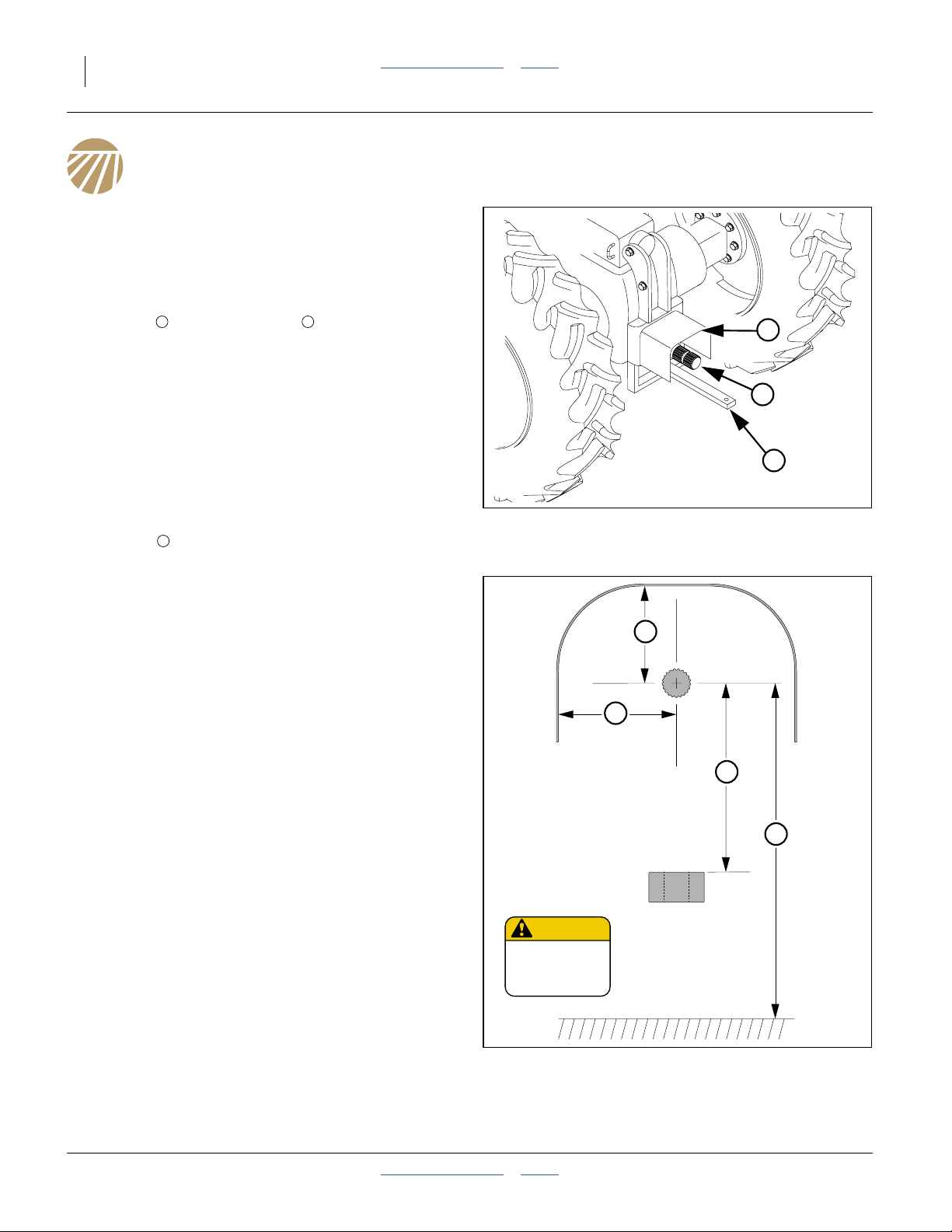
Type 2 PTO Clearance
If the tractor PTO is not known to conform to Type 2
specifications, check the following pump-specific
clearance dimensions:
Refer to Figure 3
a. Shaft to master shield top:
3.5 inches (8.9 cm) minimum
or hinged lid
b. Shaft to master shield sides:
5.0 inches (12.7 cm) minimum
c. Shaft to drawbar top:
9 inches (22.8 cm) minimum
15 inches (38.1 cm) maximum
It may be necessary to invert an offset drawbar, or
relocate or remove any clevis installed on the
drawbar.
d. Shaft to ground:
16 inches (40.6 cm) minimum
CAUTION
To avoid Injury or
Machine Damage:
·Operate only with
1000 rpm PTO
818-240C Rev. A
a
b
c
d
Figure 3:
Type 2 PTO Clearances
411-015M Table of Contents Index 2014-09-10
34844
Page 13
Great Plains Manufacturing, Inc. Table of Contents Index PTO Operation 9
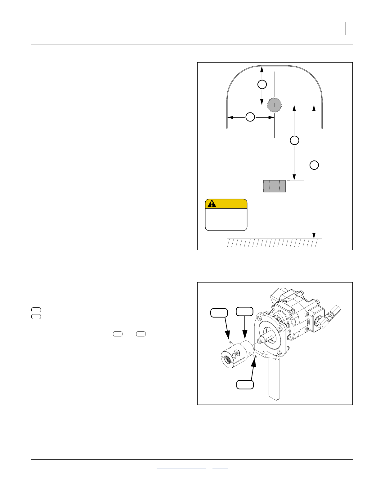
1000 rpm Type 3 PTO Clearance
If the tractor PTO is not known to conform to Type 3
specifications, check the following pump-specific
clearance dimensions:
Refer to Figure 4
a. Shaft to master shield top:
5.9 inches (15.0 cm) minimum
or hinged lid
b. Shaft to master shield sides:
7.0 inches (17.8 cm) minimum
c. Shaft to drawbar top:
8.6 inches (22.0 cm) minimum
13.75 inches (35.0 cm) maximum
It may be necessary to invert an offset drawbar, or
relocate or remove any clevis installed on the
drawbar.
d. Shaft to ground:
16 inches (40.6 cm) minimum
a
b
c
d
Install Coupler
The 1000 rpm PTO kits require one of two
tractor-specific couplers, not included with the PTO kit:
257
826-777C 1 3/4-20 PTO COUPLER
258
826-778C 1 3/8-21 PTO COUPLER
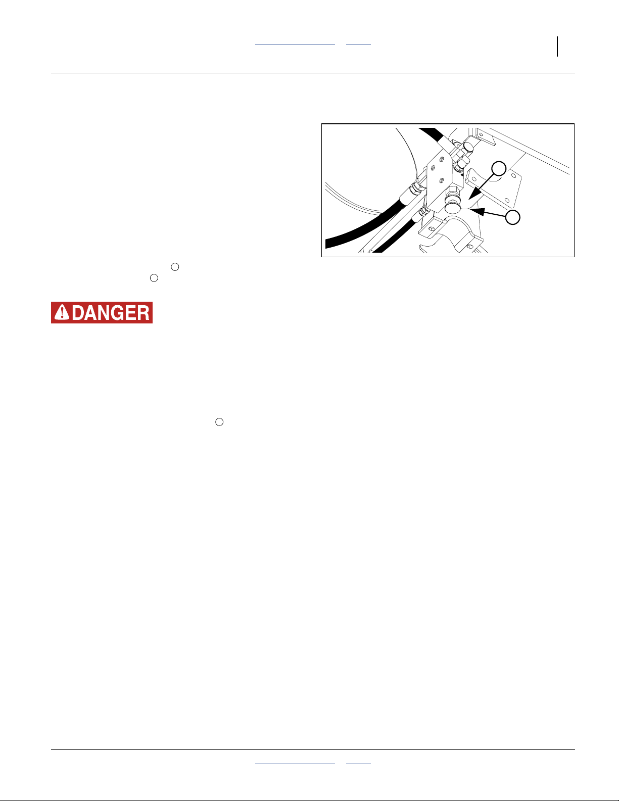
Refer to Figure 5 (showing coupler 826-778C)
1. Loosen both set screws ( and ) at the narrow
end of the coupler. Note that they are different sizes.
2. Rotate the coupler until the internal keyway aligns
with the key on the pump shaft. Slide the coupler
onto the pump shaft.
3. Tighten both set screws to the Grade 5 torque
specification for each thread size.
To remove or exchange a coupler at a later time, first
dismount the pump assembly from the tractor PTO shaft,
then loosen both set screws.
309 310
CAUTION
To avoid Injury or
Machine Damage:
·Operate only with
1000 rpm PTO
309
818-240C Rev. A
258
310
Secure Coupler to Pump
Figure 4:
Type 3 PTO Clearances
Figure 5:
34845
36315
2014-09-10 Table of Contents Index 411-015M
Page 14
10 2- & 3-Section YP PTO Pumps Table of Contents Index Great Plains Manufacturing, Inc.
Hitching with PTO
The pump may be installed before or after hitching the
planter to the tractor. If the planter has a 3-point hitch,
installing the pump first may be easier.
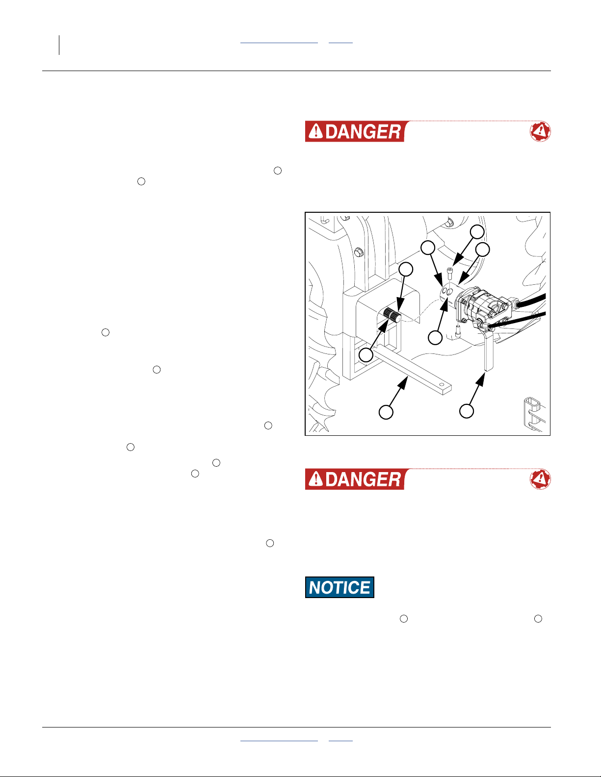
Refer to Figure 6
1. Completely remove the socket head cap screws
from the coupler .
Note: If the coupler is not mounted, or you need to
change to a different coupler, see page 9.
2. If space is constrained inside the tractor PTO shield,
rotate the coupler to an orientation that eases later
inserting and tightening of the cap screws.
2
1
Prepare Tractor
3. Back the tractor into close proximity to the planter
(within pump hose reach of the PTO shaft).
4. Shut down the tractor and remove the key.
5. Make any necessary adjustment to the tractor
drawbar . This might include:
inverting an offset drawbar, and/or
relocating a clevis assembly (not shown).
6. Clear the PTO shaft of any pins or wires that
might prevent the pump from fully seating on the
shaft.
3
4
Entanglement and Crushing Hazard:
Never perform any mechanical adjustment, PTO setup or
hitching with the tractor running. Take no chances that the
PTO might become active. Entanglement or flailing equipment
can cause serious injury or death faster than you can react.
1
8
2
4
7
6
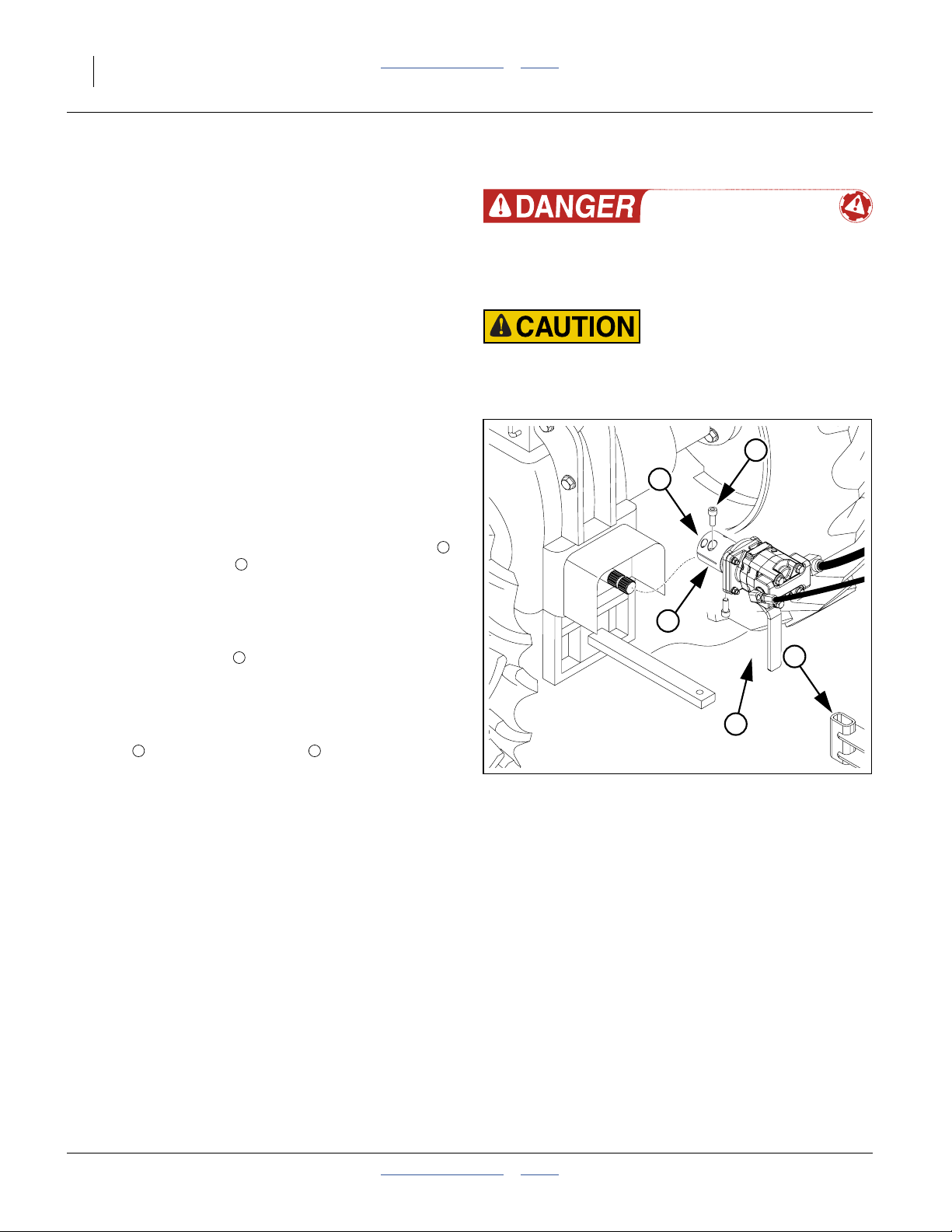
Mount and Pump
7. With hydraulics hoses to rear, and torque arm to
right of drawbar, slide the pump assembly fully onto
the PTO shaft .
8. Insert one socket head cap screw into the larger
counter-sunk clamping holes in the aft end of the
coupler. The screw head fully seats, below the
surface of the coupler, in these holes.
See NOTICE at right.
9. Adjust the position of the coupler on the shaft until
the screw threads are in the PTO shaft groove .
Thread screw in until finger tight.
10. Insert the other socket head cap screw in the other
side of the coupler. Thread it until finger tight.
11. Pull and twist the pump assembly to verify that the
socket head cap screws prevent sliding along the
PTO shaft.
12. Tighten both cap screws to1⁄2-13 Grade 8 torque
specification (105 foot-pounds, 145 N-m).
13. Complete normal planter hitching.
2
1
7
5
6
3
Figure 6:
Mount PTO Pump
Entanglement and Flailing Equipment Hazards:
Do not use a driveline, shaft extension, adaptor or external
gearbox with the PTO pump. Use the pump, with a Great
Plains coupler, only on a native 1000 rpm 20- or 21-spline
stub shaft. Extra fittings create entanglement hazards. Fittings
also destabilize the shaft, and may make it impossible to
adequately secure the pump against torque and shaft slip.
Equipment Damage Risk:
Use the clamping holes . Do not use the drive-out holes
(the smaller forward holes that are threaded to the surface).
Drive-out holes are used only during dismount. The screws
only partially thread into these holes. These holes do not
adequately secure the pump to the shaft. The pump is likely to
fall off if these holes are used for pump mounting.
7 8
5
34846
411-015M Table of Contents Index 2014-09-10
Page 15
Great Plains Manufacturing, Inc. Table of Contents Index PTO Operation 11
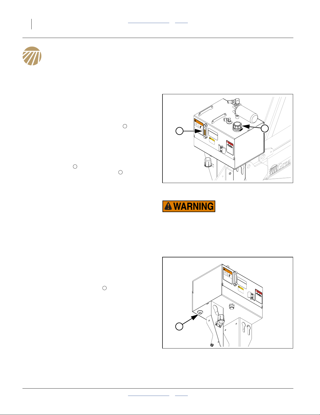
Check Hydraulics
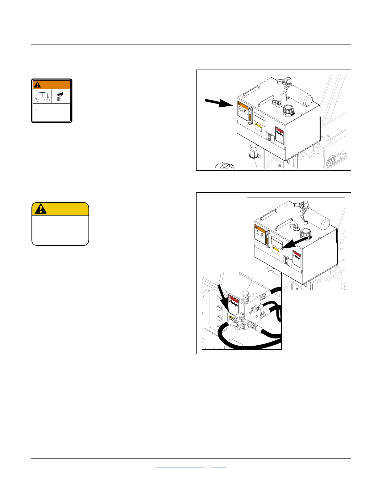
Check Oil Level
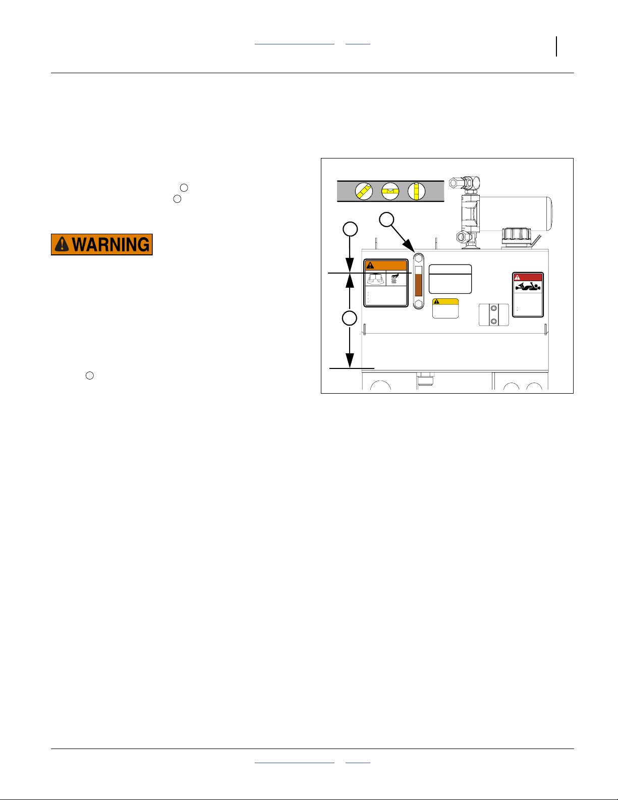
Refer to Figure 7
1. Verify that the planter is level front to back and side
to side.
2. Inspect the sight gauge on the pump system
reservoir. The oil level must be aligned with the
center border of the OIL FILL LINE decal
(858-029C).
1
2
1
2
Hot Surface and Hot Fluid Hazards:
Assess the reservoir temperature before adjusting oil level.
Draining excess hot oil could result in a severe burn. If the
PTO has been operated recently, the oil temperature could be
as high as 180°F (82°C).
3. Add or drain oil as needed to obtain the correct
amount. Some adjustment is normally required with
a new system, or after a filter change.
Note: The fill level dimension from reservoir bottom is:
a
10.73 inches (27.3 cm)
If the 858-029C decal requires replacement, adjust
the top edge of the center border line to this height.
Inspect Hoses and Fittings
4. Check that all hydraulic fittings are tight and dry.
Inspect all hoses for damage, wear and fatigue.
Because the PTO pump system is closed, any
visible fluid may be an indication of a leak.
a
WARNING
HOT FLUID HAZARD
Read Owner’s Manual BEFORE operating machine.
Keep tractor at IDLING SPEED and slowly engage PTO
to prevent damage to Hydraulic Motor
Keep Radiator clean and free of foreign matter to
prevent overheating.
Do NOT operate with hydraulic oil at or above 180°F.
OIL FILL LINE
CAPACITY = 13.5 U.S. GALS
USE ANY HIGH QUALITY MINERAL BASED
HYDRAULIC FLUID WITH A VISCOSITY RATING
OF 10W-30. OIL MUST BE CLEAN AND FREE
FROM DIRT OR CONTAMINANT PARTICLES TO
PREVENT DAMAGE TO PUMP AND MOTOR.
REPLACE FILTER ELEMENT AFTER EVERY
150 OPERATING HOURS OR 2 YEARS SERVICE.
LEVEL TOOLBAR BEFORE CHEKING OIL LEVEL
858-004C
CAUTION
To avoid Injury or
Machine Damage:
·Operate only with
1000 rpm PTO
818-240C Rev. A
Figure 7:
Check Oil Level
DANG ER
858-029C
ROTATING DRIVELINE -
CONTACT CAN CAUSE DEATH
KEEP AWAY!
DO NOT OPERATE WITHOUT-
All driveline guards, tractor
and equipment shields in place
PTO pump assembly securely
attached with torque arm and clamp
bolts properly torqued
858-030C
34847
2014-09-10 Table of Contents Index 411-015M
Page 16
12 2- & 3-Section YP PTO Pumps Table of Contents Index Great Plains Manufacturing, Inc.
Starting the Pump
While the planter is stationary, it may be necessary to
briefly operate the pump for any of several reasons:
• verify system installation or PTO operation
• verify oil level with system fully charged
• set initial meter pressurization
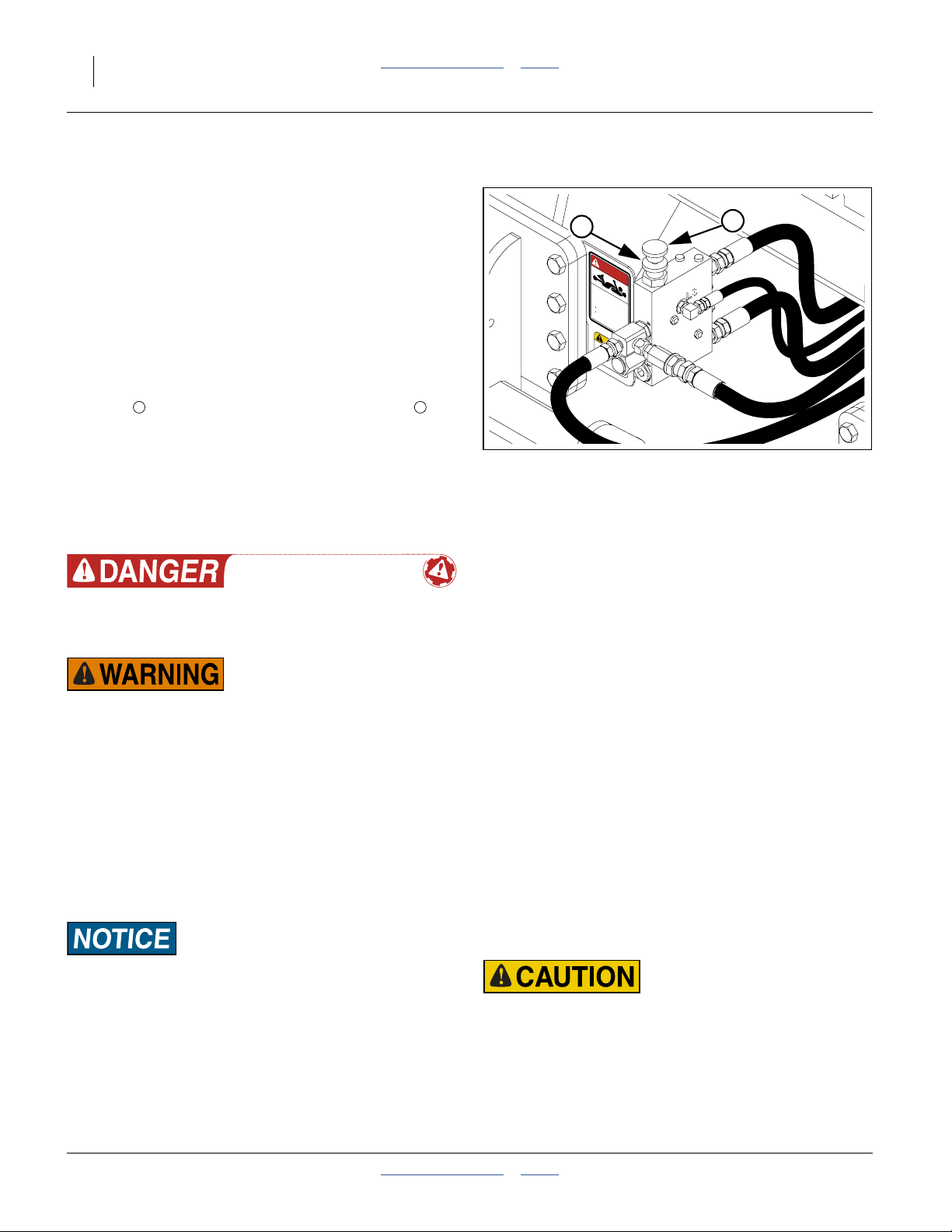
Refer to Figure 8
1. If the system is adjusted, leave the flow control
valve as-is.
If the system is not yet adjusted, close the flow
control valve to prevent fan motion. Turn the lock
1 2
disc counter-clockwise to release the knob .
Turn the knob fully clockwise to close the valve.
2. Clear the hitch area of non-essential persons.
Check essential personnel for long hair, scarves,
cords, frays, loose flaps and anything else that
might get entangled. Clear the area of dangling or
loose wires, straps, cord and other lines that might
become entangled and pull someone in.
Entanglement and Crushing Hazard:
Use extreme caution in the hitch area when the PTO is
operating.
High Pressure Fluid Hazard:
Watch for signs of fluid leaks. Escaping fluid under pressure
can have sufficient pressure to penetrate the skin causing
serious injury. Use a piece of paper or cardboard, NOT BODY
PARTS, to check for leaks. Wear protective gloves and safety
glasses or goggles when working with hydraulic systems. If an
accident occurs, seek immediate medical attention from a
physician familiar with this type of injury.
3. It is not necessary to run the PTO at the full
1000 rpm. You may run it any speed that provides
sufficient seed flow and meter pressurization
(page 13).
1
DANGER
ROTATING DRIVELINE -
CONTACT CAN CAUSE DEATH
KEEP AWAY!
DO NOT OPERATE WITHOUT-
All driveline guards, tractor
and equipment shields in place
PTO pump assembly securely
attached with torque arm and clamp
bolts properly torqued
858-030C
CAUTION
To avoid Injury or
Machine Damage:
·Operate only with
1000 rpm PTO
818-240C Rev. A
Figure 8:
Flow Control Valve (3PYPA#56)
4. • Check that tractor is in Park or Neutral.
• Check parking brake set.
• Set the tractor PTO controls for
1000 rpm gearing (if multi-speed) and
clockwise rotation (if bidirectional).
• Start tractor engine and set throttle to idle.
• Engage the PTO.
• Bring the tractor engine and PTO up to intended
field rpms.
5. Check for hydraulic fluid leaks.
6. Verify fluid level in reservoir (page 11).
About the Flow Control Valve
The flow control valve adjusts the percent of PTO pump
output that is supplied to the planter hydraulic motors.
The total pump flow, in gpm or liters/min, is also directly
proportional to PTO shaft rpm.
Adjustment may require two persons. Pump oil flow is
ideally adjusted with all hydraulic motors active under
simulated field workload, relying on seed monitor rpm
readout, and/or Magnehelic® pressure gauges.
2
34848
Equipment Damage Risk:
Do not START the pump and fan suddenly at high PTO speed.
Engage the PTO clutch slowly (if possible) and/or at low
engine rpm, and gradually increase PTO rpm. The hydraulic
fan can be damaged by sudden acceleration.
Hearing Damage Hazard:
Wear ear protection when adjusting the flow control valve. The
valve is located near the fan(s). The fan(s) must be running
during adjustment. The fan(s) are loud.
411-015M Table of Contents Index 2014-09-10
Page 17

Great Plains Manufacturing, Inc. Table of Contents Index PTO Operation 13
Flow Control Page Reference
On Great Plains Yield-Pro® 2- and 3-section planters,
the PTO pump supplies between one and three hydraulic
motors.The table below summarizes the motor count/use
and readout resource available for the covered planters.
Planter
Model
YP1220 401-936A Ground Seed Fan - - RPM Arch Frame 15
YP1225#55 401-936A Ground Seed Fan - - RPM Arch Frame 15
YP1225#56 401-934A Hydraulic Seed Fan Seed Drive - RPM Arch Frame 18
YP1225A#55 401-937A Ground Seed Fan - - RPM Arch Frame 15
YP1225A#56 401-935A Hydraulic Seed Fan Seed Drive - RPM Arch Frame 14
YP1625#55 401-936A Ground Seed Fan - - RPM Arch Frame 15
YP1625#56 401-934A Hydraulic Seed Fan Seed Drive - RPM Arch Frame 18
YP1625A#55 401-937A Ground Seed/Meter Fan - - RPM Arch Frame 15
YP1625A#56 401-935A Hydraulic Seed/Meter Fan Seed Drive - RPM Arch Frame 14
YP1630F 401-938A Ground Fertilizer Fan - - in. H2O Seed Cart 19
YP2425 401-943A Hydraulic Seed Fan Seed Drive - RPM Walkboard 18
YP2425A 401-944A Hydraulic Seed/Meter Fan Seed Drive - RPM Walkboard 14
YP2425F 411-014A Hydraulic Fertilizer Fan Seed Fan Seed Drive RPM Walkboard 18
YP3010HDP 401-945A Hydraulic Seed Fan Seed Drive - RPM Mainframe LH 18
YP3020P 401-945A Hydraulic Seed Fan Seed Drive - RPM Mainframe LH 18
YP3025 401-945A Hydraulic Seed Fan Seed Drive - RPM Mainframe LH 18
YP3025A/AR 401-946A Hydraulic Seed/Meter Fan Seed Drive - RPM Fan Mast 14
YP4010HDP 401-945A Hydraulic Seed Fan Seed Drive - RPM Mainframe LH 18
YP4020P 401-945A Hydraulic Seed Fan Seed Drive - RPM Mainframe LH 18
YP4025 401-945A Hydraulic Seed Fan Seed Drive - RPM Mainframe LH 18
YP4025A/AR 401-946A Hydraulic Seed/Meter Fan Seed Drive - RPM Fan Mast 14
YP4025F 401-945A Hydraulic Fertilizer Fan Seed Drive - RPM Mainframe LH 18
YP4425A 401-951A Hydraulic Seed Fan Seed Drive - RPM Fan Mast 14
1625AHD 411-147A Ground Fert/Meter Fan - - in. H2O
1625AHL 411-138A Ground Meter Fan - - in. H2O
3PYP#55 401-941A Ground Seed Fan - - RPM Hitch 15
3PYP#56 401-939A Hydraulic Seed/Meter Fan Seed Drive - RPM Hitch 18
3PYPA#55 401-942A Ground Seed/Meter Fan - - RPM Hitch 15
3PYPA#56 401-940A Hydraulic Seed/Meter Fan Seed Drive - RPM Hitch 14
a
a. The “#” notation indicates the Feature Code used to specify ground drive (#55) or hydraulic drive (#56) seed metering.
b. A readout of fan rpm is also available on the console for reference.
PTO
Kit
Seed
Drive
First
Motor
Second
Motor
Third
Motor
Fan
Adjust
Valve
Location
b
Walkboard 17
b
Cart Strut 16
Page
2014-09-10 Table of Contents Index 411-015M
Page 18
14 2- & 3-Section YP PTO Pumps Table of Contents Index Great Plains Manufacturing, Inc.
Flow Adjust: Hydraulic Drive Center-Fill
IntelliAg
On hydraulic drive models YP1225A#56, YP1625A#56,
YP2425A, YP3025A/AR, YP4025A/AR, YP4425A and
3PYPA#56, the PTO system drives two
plumbed in parallel:
a. The fan motor generates an airflow for seed delivery
b. The seed meter shaft motor is under seed monitor
Adjustment Steps:
1. Have the DICKEY-john® Planter/Drill Control User
2. Have the Operator and Seed Rate manuals at hand,
3. Loading seed is not required. If you do load seed,
4. Turn the IntelliAg® monitor system on.
5. Set:
6. Hitch the tractor to be used, and install the PTO
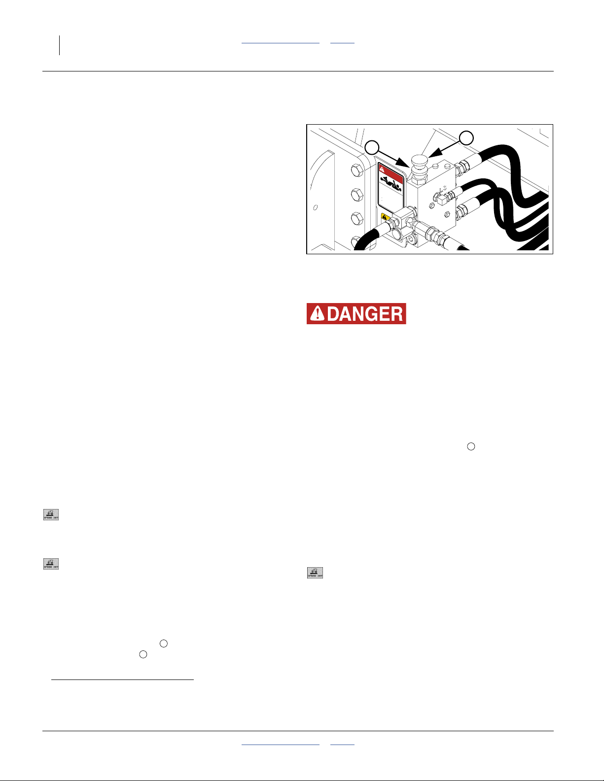
Refer to Figure 9
7. Release the lock disc counter-clockwise to
®
Air-Pro® Planters
a
motors,
and meter pressurization. The ratio is servo vane
controlled by the DICKEY-john®IntelliAg® seed
monitor. The vane needs to be active for accurate
flow control adjustments.
control, via a proportional flow solenoid valve. When
engaged at typical seed rates, operating this motor
reduces flow to the fan motor. The seed motor needs
to be engaged at least briefly during setup to choose
a flow rate that keeps the fan at optimal speed.
Level 2&3 manual at hand. Making changes to the
GROUND SPEED SETUP configuration requires
the Level 2 password.
so that meter setting and fan rpm targets are known
for the seed to be planted.
set out recovery means to capture seed metered
during testing, or use section clutchesb to disable
metering.
Turn the Master switch off.
On the console, navigate to the
GROUND SPEED SETUP screen.
Record the ground speed constant:
Source
Gspd Constant
Source
Manual Gnd Spd
Implement Lift
Digital Freq.
12345 (actual value varies)
Manual
5.0 MPH (or as desired)
Disabled
pump. Raise the planter. Unfold the planter.
1
release the knob . Turn the knob fully clockwise to
2
shut off flow to the motors.
1
2
DANGER
ROTATING DRIVELINE -
CONTACT CAN CAUSE DEATH
KEEP AWAY!
DO NOT OPERATE WITHOUT-
All driveline guards, tractor
and equipment shields in place
PTO pump assembly securely
attached with torque arm and clamp
bolts properly torqued
858-030C
CAUTION
To avoid Injury or
Machine Damage:
·Operate only with
1000 rpm PTO
818-240C Rev. A
Figure 9:
Flow Control Valve (3PYPA#56)
Entanglement and Crushing Hazard:
Use extreme caution in the hitch area when the PTO is
operating.
8. Start the tractor, and seed monitor. Bring the PTO
up to expected field rpm (which is often not the full
1000 rpm).
9. Turn the IntelliAg® Master switch on to engage the
hydraulic seed meter drive.
10. With one person observing the fan rpm readout on
the seed monitor, turn the knob
2
counter-clockwise until the fan is at the rpm
recommended for this planter configuration, crop,
population and intended field speed.
Secure the knob at this setting with the lock disc.
11. Shut down the PTO. Set Master switch off.
12. On the console, navigate to the
GROUND SPEED SETUP screen.
Restore the original settings:
Source
Gspd Constant
Implement Lift
Digital Freq.
12345 (actual value varies)
Enabled
Monitor fan rpm when planting. If it is lower than during
flow setup, perform the setup steps again, and set the
valve for a higher rpm.
34848
a. When the Yield-Pro® PTO pump system was installed, there was an option to use it only for the air system, and leave the hydraulic
drive on a dedicated tractor connection. In this case, load seed, but ignore the steps to compensate for seed drive motor load.
b. If Swath Command™ section control is installed, connect the compressor at the hitch, or clutches will not disengage.
411-015M Table of Contents Index 2014-09-10
Page 19
Great Plains Manufacturing, Inc. Table of Contents Index PTO Operation 15
Flow Adjust: Ground Drive IntelliAg
®
Center-Fill Planters
On ground drive models YP1220, YP1225#55,
YP1225A#55, YP1625#55, YP1625A#55, YP1630F,
3PYP#55 and 3PYPA#55, the PTO system drives one
motor, the fan supplying air for seed delivery and meter
pressurization. The air ratio is servo vane controlled by
the seed monitor. The vane needs to be active for
accurate flow control adjustments.
Adjustment Steps:
1. Hitch the tractor to be used, and install the PTO
pump. Raise the planter. Unfold the planter.
Refer to Figure 10
2. Release the lock disc counter-clockwise to
release the knob . Turn the knob fully clockwise to
shut off flow to the motors.
Entanglement and Crushing Hazard:
Use extreme caution in the hitch area when the PTO is
operating.
3. Start the tractor, and seed monitor. Bring the PTO
up to expected field rpm (which is often not the full
1000 rpm).
4. With one person observing the fan rpm readout on
the seed monitor, turn the knob
counter-clockwise until the fan is at the rpm
recommended for this planter configuration, crop,
population and intended field speed.
1
2
2
1
2
Figure 10:
Flow Control Valve (YP1625#55)
36338
Secure the knob at this setting with the lock disc.
5. Monitor fan rpm when planting. If it is lower than
during flow setup, perform the setup steps again,
and set the valve for a higher rpm.
2014-09-10 Table of Contents Index 411-015M
Page 20

16 2- & 3-Section YP PTO Pumps Table of Contents Index Great Plains Manufacturing, Inc.
Flow Adjust: Ground Drive Row-Hopper
Air-Pro
On planter models 1625AHL, the PTO system drives the
fan motor, which is used only for seed meter
pressurization.
The seed monitor console reports, but does not control
fan rpm, and the value noted during adjustment can be
useful afield and during later setups.
Adjustment Steps:
Refer to Figure 11
1. Consult your planter Seed Rate manual for the
2. Install seed disks. Leave rain covers off meters.
3. Set meter inlet shutters per the Seed Rate manual.
4. Open any slide gates under hoppers.
5. Load enough seed to completely fill the meter inlet
6. Set out containers, under row unit seed tubes, to
7. Clear the hitch area of non-essential persons.
8. Configure the meter drive system sprockets for the
9. Per your planter Operator manual, hitch the planter.
10. • Check that tractor is in Park or Neutral.
®
(Meter-Only) Planters
intended crop, noting:
• Range and Transmission sprockets required,
• correct Air-Pro
• initial inlet shutter setting (not shown), and
• initial meter pressurization.
tubes, and at least partially fill every hopper.
collect seed metered during setup.
Check essential personnel for long hair, scarves,
cords, frays, loose flaps and anything else that
might get entangled. Clear the area of dangling or
loose wires, straps, cord and other lines that might
become entangled and pull someone in.
rate desired (see Seed Rate Manual).
Raise the planter. Install lift locks. This is to free the
meter ground drive wheel.
• Check parking brake set.
• Set the tractor PTO controls for
1000 rpm gearing (if multi-speed) and
clockwise rotation (if bidirectional).
• Start tractor engine and set throttle to idle.
• Engage the PTO.
• Bring the tractor engine and PTO up to intended
field rpms.
®
seed disk (not shown),
1
2
3
Figure 11:
Flow Control Valve (1625AHL)
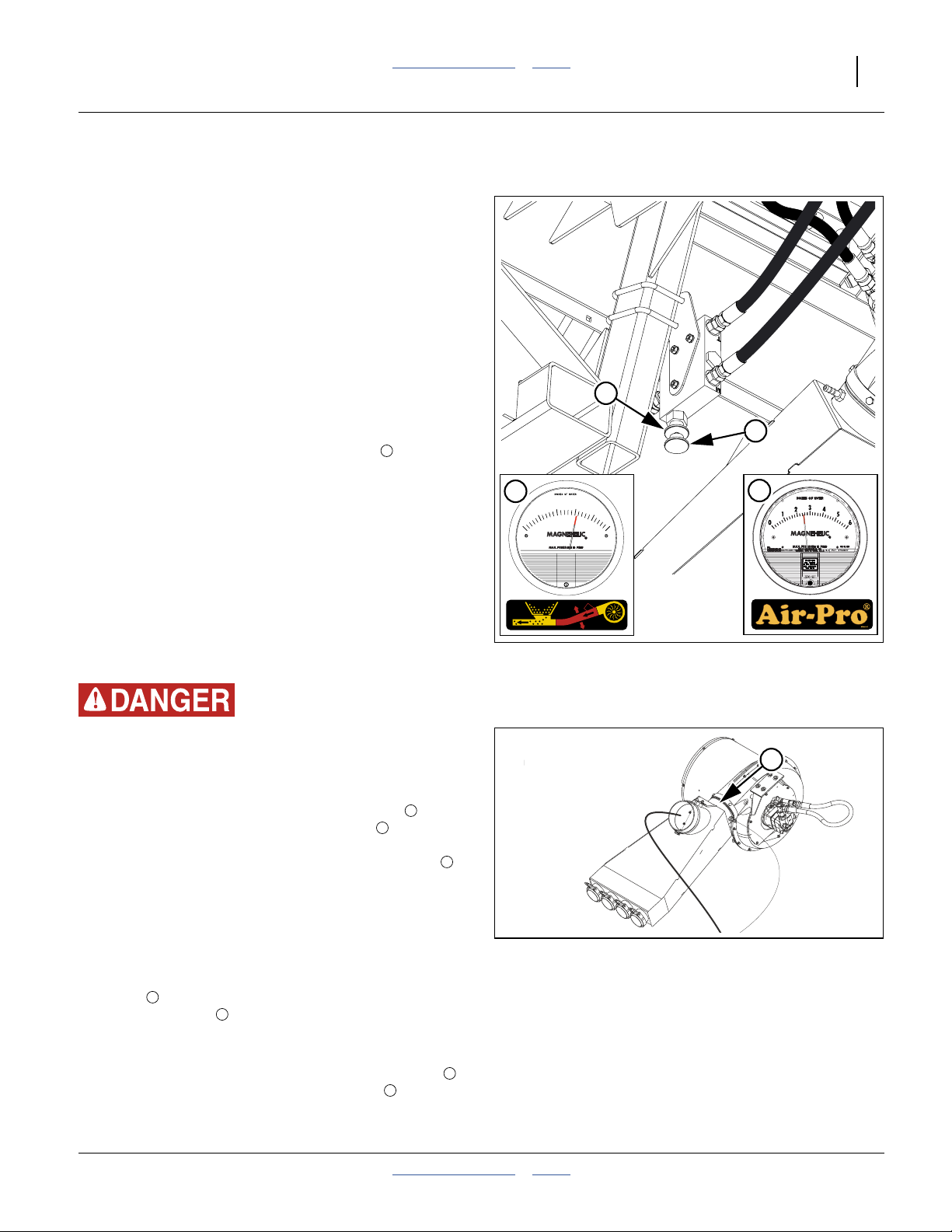
11. At the flow control valve, turn the lock disc
counter-clockwise to release the knob . Slowly
turn the knob counter-clockwise to start the fan.
Bring the fan speed up until the Magnehelic
gauge displays the suggested pressure for this
crop.
12. Turn the meter ground drive wheel forward several
turns, until all exposed cells in all seed disks contain
seed.
13. Recheck the Magnehelic® gauge. The reported
pressure is likely to have increased. Adjust the flow
control knob to bring the pressure reading back to
the recommended value. Tighten the lock disc.
14. Shut down the PTO, and as desired, the tractor.
15. Install rain covers on seed meters.
3
36340
1
2
®
411-015M Table of Contents Index 2014-09-10
Page 21
Great Plains Manufacturing, Inc. Table of Contents Index PTO Operation 17
Flow: Ground Drive Row-Hopper Air-Pro
®
Dry Fertilizer Planters
On model 1625AHD planters, the PTO pump drives a
single fan which delivers dry fertilizer and pressurizes the
seed meters. Setting and balancing pressures is a
manual operation. The seed monitor reports fan rpm.
Review the air system overview, fan operation, and
butterfly valve adjustment in the 411-020M Operator
manual before adjusting for PTO operation.
1. Look up the recommended meter pressurization for
the intended crop (see Seed Rate manual). Make a
note of the previous or factory settings of all butterfly
valves. Load seed in hoppers and meters. Meters
must be full to inlet shutters for valid readings.
Refer to Figure 13
2. Close the manifold outlet butterfly valve
(set to 90°). If the wing butterfly valves have been
previously adjusted for balance, leave them
undisturbed, otherwise set them full open (0°).
3. • Check that tractor is in Park or Neutral.
• Check parking brake set.
• Set the tractor PTO controls for
1000 rpm gearing (if multi-speed) and
clockwise rotation (if bidirectional).
• Start tractor engine and set throttle to idle.
• Engage the PTO.
• Bring the tractor engine and PTO up to intended
field rpms.
5
1
2
3
20
30
10
0
40
50
858-193C
Figure 12:
Flow Control Valve (1625AHL)
4
36339
29842
Entanglement and Crushing Hazard:
Use extreme caution in the hitch area when the PTO is
operating.
5
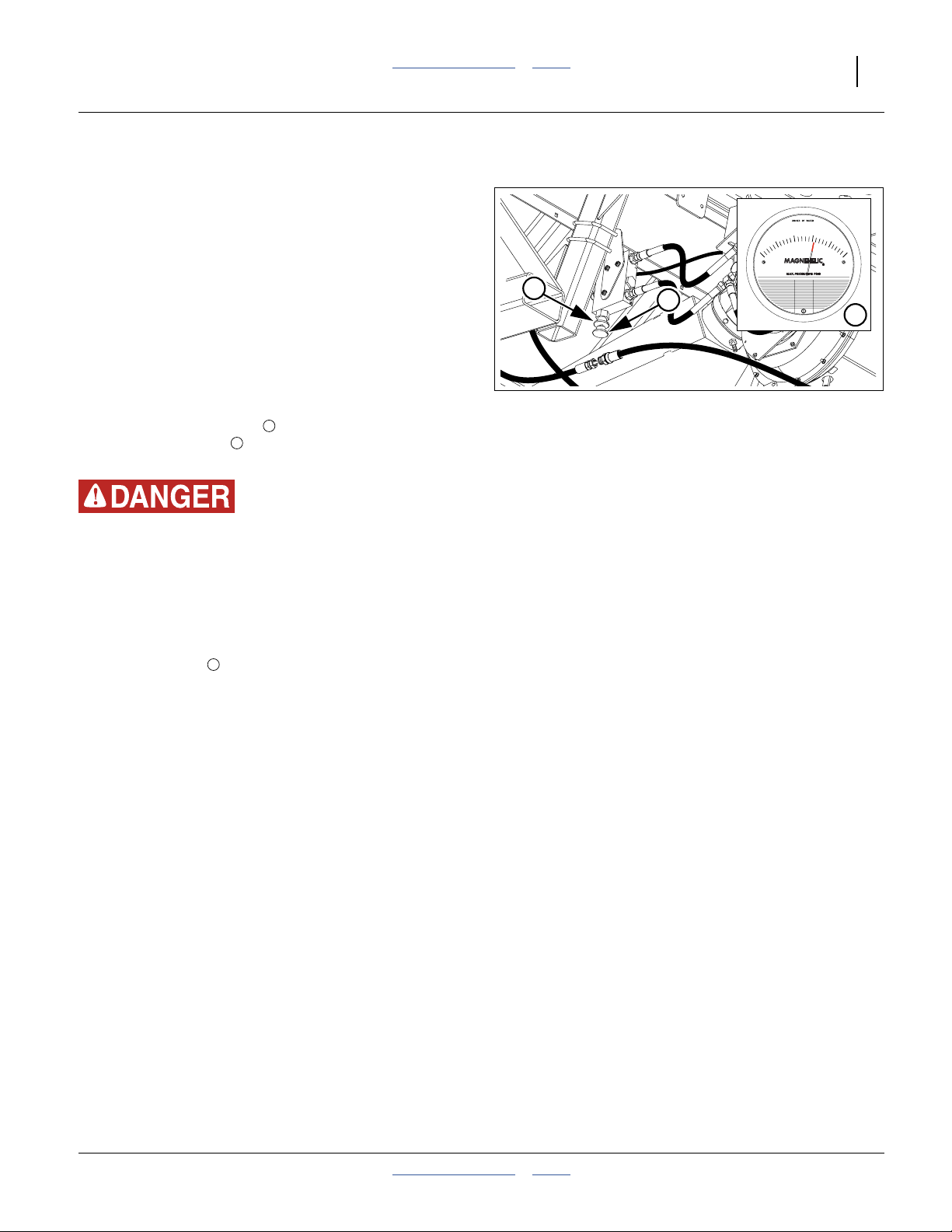
Refer to Figure 12
4. At the flow control valve, turn the lock disc
counter-clockwise to release the knob . Slowly
1
2
turn the knob counter-clockwise to start the fan.
Bring the fan speed up until the Air-Pro® gauge
4
displays the suggested pressure for this crop.
Secure the lock disc.
5. Raise the planter. Turn each meter ground drive
wheel (2 or 3 per planter) forward several turns, until
all exposed cells in all seed disks contain seed.
6. As necessary, readjust manifold outlet butterfly
5
valve to achieve recommended pressure on the
Air-Pro® gauge .
4
Figure 13
Fertilizer Manifold Butterfly Valve
36134
858-208C
7. Re-check both pressures in the field, with material
flowing at desired rates. Adjust fan speed to stay
within 35 to 45 inches on the fan manifold gauge .
Adjust the manifold outlet butterfly valve to the
5
3
suggested pressure for the seed.
2014-09-10 Table of Contents Index 411-015M
Page 22
18 2- & 3-Section YP PTO Pumps Table of Contents Index Great Plains Manufacturing, Inc.
Flow Adjust: Hydraulic Drive IntelliAg
®
Singulator Plus™ & Finger Pick-Up Planters
On hydraulic drive models YP1225#56, YP1625#56,
YP2425, YP2425F, YP3010HDP, YP3020P, YP3025,
YP4010HDP, YP4020P, YP4025, YP4025F and
3PYP#56, the PTO system drives twoa or three motors,
plumbed in parallel:
a. One fan motor (two on model YP2425F) generates
an airflow for seed delivery and/or fertilizer delivery
(models YP2425F, YP4025F).
b. The other motor, for seed meter operation, is under
seed monitor control, via a proportional flow solenoid
valve.
When engaged at typical field seed rates, the seed drive
motor reduces flow to the delivery fan. The seed motor
needs to be engaged at least briefly during setup to
choose a flow rate that keeps the delivery fan at optimal
speed.
Adjustment Steps:
1. Have the DICKEY-john
Level 2&3 manual at hand. Making changes to the
GROUND SPEED SETUP configuration requires
the Level 2 password.
2. Have the Operator and Seed Rate manuals at hand,
so that the fan rpm target is known for the seed to
be planted.
3. Loading seed is not required. Loading fertilizer is
not recommended. If you do load seed, set out
recovery means to capture seed metered during
testing, or use section clutchesb to disable
metering.
4. Turn the IntelliAg® monitor system on.
Turn the Master switch off.
On the console, navigate to the
GROUND SPEED SETUP screen.
Record the ground speed constant:
Source
Gspd Constant
5. Set:
Source
Manual Gnd Spd
Implement Lift
6. Hitch the tractor to be used, and install the PTO
pump. Raise the planter. Unfold the planter.
®
Planter/Drill Control User
Digital Freq.
12345 (actual value varies)
Manual
5.0 MPH (or as desired)
Disabled
1
2
DANGER
ROTATING DRIVELINE -
CONTACT CAN CAUSE DEATH
KEEP AWAY!
DO NOT OPERATE WITHOUT-
All driveline guards, tractor
and equipment shields in place
PTO pump assembly securely
attached with torque arm and clamp
bolts properly torqued
858-030C
CAUTION
To avoid Injury or
Machine Damage:
·Operate only with
1000 rpm PTO
818-240C Rev. A
Figure 14:
Flow Control Valve (3PYP#56)
Refer to Figure 14
7. Release the lock disc counter-clockwise to
release the knob . Turn the knob fully clockwise to
1
2
shut off flow to the motors.
Entanglement and Crushing Hazard:
Use extreme caution in the hitch area when the PTO is
operating.
8. Start the tractor, and seed monitor. Bring the PTO
up to expected field rpm (which is often not the full
1000 rpm).
9. Turn the IntelliAg® Master switch on to engage the
hydraulic seed meter drive.
10. With one person observing the fan rpm readout on
the seed monitor, turn the knob
2
counter-clockwise until the fan is at the rpm
recommended for this planter configuration, crop,
population and intended field speed.
Secure the knob at this setting with the lock disc.
11. Shut down the PTO. Set Master switch off.
12. On the console, navigate to the
GROUND SPEED SETUP screen.
Restore the original settings:
Source
Gspd Constant
Implement Lift
Digital Freq.
12345 (actual value varies)
Enabled
Monitor fan rpm when planting. If it is lower than during
flow setup, perform the setup steps again, and set the
valve for a higher rpm.
34848
a. If the Yield-Pro® PTO pump system was ordered for ground drive, the hydraulic drive is still on a dedicated circuit. In this case, load
seed, but ignore the steps to compensate for seed drive motor load.
b. If Swath Command™ section control is installed, connect the compressor at the hitch, or clutches will not disengage.
411-015M Table of Contents Index 2014-09-10
Page 23
Great Plains Manufacturing, Inc. Table of Contents Index PTO Operation 19
Flow: Ground Drive Row Hopper Finger Pick-Up & Brush Meter Planters
On models YP1630F, the PTO system drives one motor,
for the fertilizer delivery fan.
Adjustment Steps:
1. Have the Operator and Seed Rate manuals at hand,
so that the fan rpm target is known for the material
to be applied and the rate range.
Note: Loading material is not required. The fertilizer
meter does not operate during this setup.
2. Hitch the tractor to be used, and install the PTO
pump. Raise the planter.
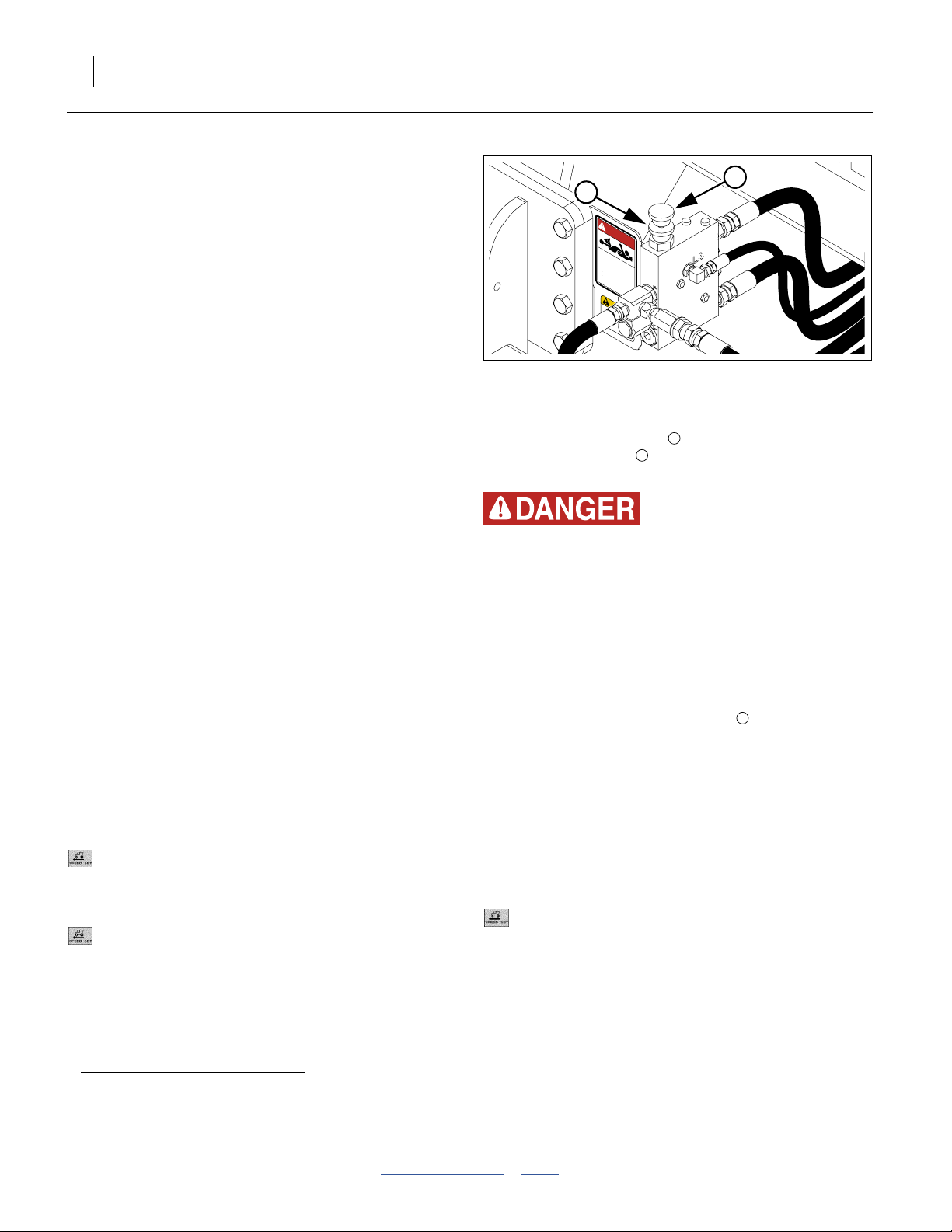
Refer to Figure 15
3. Release the lock disc counter-clockwise to
release the knob . Turn the knob fully clockwise to
1
2
shut off flow to the motors.
1
2
Figure 15:
Flow Control Valve (YP1630F)
and Magnehelic® Gauge
20
30
10
0
40
50
2
34849
31187
Entanglement and Crushing Hazard:
Use extreme caution in the hitch area when the PTO is
operating.
4. Start the tractor, and seed monitor. Bring the PTO
up to expected field rpm (which is often not the full
1000 rpm).
5. With one person observing the Magnehelic®gauge,
turn the knob counter-clockwise until the fan is at
2
the recommended pressure for this planter
configuration, fertilizer and application rate.
Secure the knob at this setting with the lock disc.
6. Shut down the PTO.
Monitor pressure when planting. If it is lower than during
flow setup, perform the setup steps again, and set the
valve for a higher pressure.
2014-09-10 Table of Contents Index 411-015M
Page 24
20 2- & 3-Section YP PTO Pumps Table of Contents Index Great Plains Manufacturing, Inc.
PTO Unhitching
The pump may be dismounted before or after unhitching
the planter and tractor. With a 3-point planter or 3-point
hitch, dismounting the pump last may be easier, which is
the order shown on this page. For safety, have the tractor
completely shut down during PTO dismounting.
1. At the tractor, shut down the PTO.
Note: The PTO may be shut down suddenly or gradually.
The fan circuit includes a bypass to recirculate
excess pressure during deceleration. The fan is
only sensitive to sudden acceleration.
2. Do not approach the hitch area until the PTO shaft,
and the fan, have slowed to a complete stop.
3. Mechanically unhitch the planter per the Operator
manual. Leave the PTO pump mounted at this time.
4. Pull the tractor forward enough to allow access to
the PTO pump. Put the tractor in Park or Neutral.
Engage the parking brake. Shut the tractor down.
Remove the key.
5. Loosen and remove the socket head cap screws
at the PTO coupler .
6. Slide the PTO pump off the PTO shaft.
2
Entanglement Hazard:
Remain clear of a rotating PTO shaft. Even when coasting to a
stop, a PTO shaft can have enough residual torque to inflict
serious or fatal injury.
Hot Surface Hazard:
Remain clear of the pump reservoir during unhitching.
The oil may be hot enough to inflict a painful burn.
1
3
1
If, after removing the cap screws, the coupler is still
grasping the PTO shaft too tightly to remove, use
the drive-out holes to pry the clamping halves
apart. Insert the cap screws in the forward drive-out
holes. Tighten them alternately until the coupler is
free.
7. Store the pump on the planter. Insert the torque
5 5
arm into the storage mount .
The storage mount is located on the front of a
3-point hitch and on the right side of a pull-type
tongue at the hitch bolts.
3
2
4
Figure 16:
Dismount PTO Pump
5
34846
411-015M Table of Contents Index 2014-09-10
Page 25

Great Plains Manufacturing, Inc. Table of Contents Index 21
PTO Troubleshooting
Symptom Cause Remedy
Air-Pro
®
seed meter
pressure too low
Pressure correct on
®
Magnehelic
, but
skips or doubles
Oil overheating
Fan running in
reverse
Fan doesn’t run at all
Flow control adjusted too low Increase flow control (page 13).
Fan butterfly valve closed or set at too high
an angle
PTO rpm too low Bring up PTO rpm, but do not exceed
Fan running in reverse (multiple possible
causes)
Pump cavitating Check oil level (page 11).
No blank disks in unused seed meters Install blank disks to balance pressure.
Seed inlet shutters open too wide Verify setting vs., rate charts. Adjust as
Oil filter clogged Replace oil filter and oil (page 22).
Magnehelic® gauge disconnected or
sample line(s) leaking
Magnehelic® gauge uncalibrated Re-zero (see Operator manual).
Flow control valve failure or malfunction Repair or replace valve.
Fan seals damaged Repair or replace fan motor.
PTO rotation and fan or valve hoses
reversed (highly unlikely)
Fan cooler plugged Clean or replace fan cooler.
Pressure gauge disconnected or sample
line(s) leaking.
Magnehelic® gauge uncalibrated. Re-zero (see Operator manual).
Seed variety may require adjustment. Check all other possible pressure errors,
Oil filter clogged Replace oil filter and oil (page 22).
PTO rpm too high Adjust system for ideal pressure at lower
Fan butterfly valve angle too high Reduce to 30° (see planter Operator
PTO shaft turning counter-clockwise Set tractor controls for clockwise PTO.
Hoses reversed Check hose routing from pump to valve, to
Low oil level in reservoir Top off reservoir. Check system for leaks.
Flow control valve closed Adjust valve (page 13).
Hoses misconnected Review installation (page 49).
Adjust angle (see Operator manual).
1000 rpm.
See “Fan running in reverse” below.
need for actual seed pool.
Check air gauging system.
Set tractor controls for clockwise PTO.
Reconnect hoses.
Check air gauging system.
then fine tune pressure for one seed per
disk cell.
PTO rpm.
manual).
reservoir and fan per Parts manual.
2014-09-10 Table of Contents Index 411-015M
Page 26
22 2- & 3-Section YP PTO Pumps Table of Contents Index Great Plains Manufacturing, Inc.
PTO Maintenance
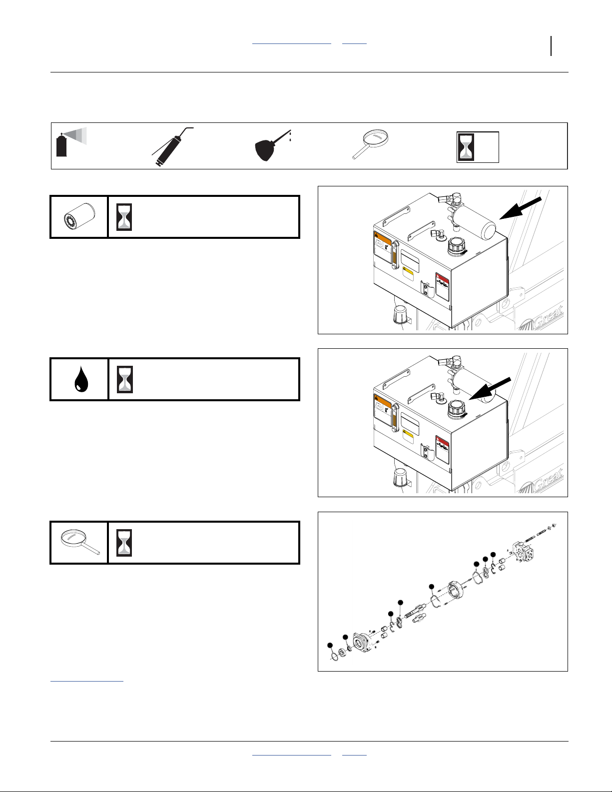
Oil and Filter Change
Oil Fill
Refer to Figure 17 and Figure 18
A dry or fully drained system may require as much as
20 gallons (76 liters) of oil to charge the cooler, pump,
motor(s), hoses, filter and valve, and leave 13.5 gallons
(51 liters) in the reservoir.
Before adding oil, check that the drain plug is secure,
1
and that there are no signs of leaks in hoses or at any
system fittings.
Oil Specification
10W-30 good quality mineral base hydraulic fluid,
viscosity 70 to 250 SUS at 210°F (100°C)
Remove the filler cap . Add oil until the oil level in the
reservoir, as observed on the sight gauge , reaches the
2
3
fill line on the decal (the top edge of the horizontal
mid-border of the decal). The fill line is 10.73 inches
(27.3 cm) above the reservoir bottom. If the 858-029C
decal requires replacement, adjust the center border line
to this height.
Operate the PTO system briefly, or until the reservoir
level stops changing. See “PTO Operation” on page 8
for operations.
Recheck the sight gauge. As necessary, add oil to fill
line.
Oil and Filter Change
At a regularly scheduled oil change, also change the
filter. At initial system flush, no filter change is required.
Refer to Figure 18 and Figure 17
1. Wait for the oil to cool before changing the oil.
2. Place a container with at least a 20 gallon (76 liter)
capacity under the drain plug of the reservoir.
3. Carefully remove the drain plug.
4. Allow several minutes for oil in the filter to drain into
and out of the reservoir. Change filter as required.
See page 23 for filter size. Seat filter per
instructions on filter.
5. Thread the plug back into the reservoir. Seating
torque is 27 to 43 foot-pounds (37 to 58 N-m).
1
3
Hot Surface and Hot Fluid Hazards:
Assess the reservoir temperature before adjusting oil level.
Draining excess hot oil could result in a severe burn. If the
PTO has been operated recently, the oil temperature could be
as high as 180°F (82°C).
1
WARNING
HOT FLUID HAZARD
Read Owner’s Manual BEFORE operating machine.
Keep tractor at IDLING SPEED and slowly engage PTO
to prevent damage to Hydraulic Motor
Keep Radiator clean and free of foreign matter to
prevent overheating.
OIL FILL LINE
Do NOT operate with hydraulic oil at or above 180°F.
CAPACITY = 13.5 U.S. GALS
USE ANY HIGH QUALITY MINERAL BASED
HYDRAULIC FLUID WITH A VISCOSITY RATING
OF 10W-30. OIL MUST BE CLEAN AND FREE
FROM DIRT OR CONTAMINANT PARTICLES TO
PREVENT DAMAGE TO PUMP AND MOTOR.
REPLACE FILTER ELEMENT AFTER EVERY
858-004C
150 OPERATING HOURS OR 2 YEARS SERVICE.
LEVEL TOOLBAR BEFORE CHEKING OIL LEVEL
CAUTION
To avoid Injury or
858-029C
Machine Damage:
·Operate only with
1000 rpm PTO
DANGER
818-240C Rev. A
ROTATING DRIVELINE -
CONTACT CAN CAUSE DEATH
KEEP AWAY!
DO NOT OPERATE WITHOUT-
All driveline guards, tractor
and equipment shields in place
PTO pump assembly securely
attached with torque arm and clamp
bolts properly torqued
858-030C
Figure 17:
Oil Filler Cap and Filter
WARNING
HOT FLUID HAZARD
Read Owner’s Manual BEFORE operating machine.
Keep tractor at IDLING SPEED and slowly engage PTO
to prevent damage to Hydraulic Motor
Keep Radiator clean and free of foreign matter to
prevent overheating.
Do NOT operate with hydraulic oil at or above 180°F.
USE ANY HIGH QUALITY MINERAL BASED
HYDRAULIC FLUID WITH A VISCOSITY RATING
OF 10W-30. OIL MUST BE CLEAN AND FREE
FROM DIRT OR CONTAMINANT PARTICLES TO
PREVENT DAMAGE TO PUMP AND MOTOR.
REPLACE FILTER ELEMENT AFTER EVERY
858-004C
150 OPERATING HOURS OR 2 YEARS SERVICE.
LEVEL TOOLBAR BEFORE CHEKING OIL LEVEL
OIL FILL LINE
CAPACITY = 13.5 U.S. GALS
CAUTION
To avoid Injury or
Machine Damage:
·Operate only with
1000 rpm PTO
2
34843
858-029C
DANGER
818-240C Rev. A
ROTATING DRIVELINE -
CONTACT CAN CAUSE DEATH
KEEP AWAY!
DO NOT OPERATE WITHOUT-
All driveline guards, tractor
and equipment shields in place
PTO pump assembly securely
attached with torque arm and clamp
bolts properly torqued
858-030C
Figure 18:
34850
Oil Drain Plug
411-015M Table of Contents Index 2014-09-10
Page 27
Great Plains Manufacturing, Inc. Table of Contents Index PTO Maintenance 23
Lubrication and Scheduled Maintenance
Intervals
Multi-purpose
spray lubricant
Multi-purpose
grease lubricant
Multi-purpose
oil lubricant
Inspection
34208
(operating hours)
50
at which service
is required
Oil Filter
25 / 150
WARNING
HOT FLUID HAZARD
1 filter per planter
Type: Great Plains 891-385C
Fleetguard HF6611
Zinga HE-10L
Change filter after first 25 hours, and then every 2 years
or 150 hours.
34843
Read Owner’s Manual BEFORE operating machine.
Keep tractor at IDLING SPEED and slowly engage PTO
to prevent damage to Hydraulic Motor
Keep Radiator clean and free of foreign matter to
prevent overheating.
Do NOT operate with hydraulic oil at or above 180°F.
OIL FILL LINE
CAPACITY = 13.5 U.S. GALS
USE ANY HIGH QUALITY MINERAL BASED
HYDRAULIC FLUID WITH A VISCOSITY RATING
OF 10W-30. OIL MUST BE CLEAN AND FREE
FROM DIRT OR CONTAMINANT PARTICLES TO
PREVENT DAMAGE TO PUMP AND MOTOR.
REPLACE FILTER ELEMENT AFTER EVERY
858-004C
150 OPERATING HOURS OR 2 YEARS SERVICE.
LEVEL TOOLBAR BEFORE CHEKING OIL LEVEL
CAUTION
To avoid Injury or
858-029C
Machine Damage:
·Operate only with
1000 rpm PTO
DANGER
818-240C Rev. A
ROTATING DRIVELINE -
CONTACT CAN CAUSE DEATH
KEEP AWAY!
DO NOT OPERATE WITHOUT-
All driveline guards, tractor
and equipment shields in place
PTO pump assembly securely
attached with torque arm and clamp
bolts properly torqued
858-030C
Pump/Fan Oil
300 or 4 Years
1 reservoir per planter
Type: 10W-30 Mineral-Based Oil
70 to 250 SUS at 210°F (100°C)
Quantity: 13.5 U.S. gallons (51 liters)
Change filter when changing oil, except at initial system
flush.
Seal Kit
As Needed
1 kit per planter, includes snap ring and all seals
Type: 810-901C for Parker 350C pumps
810-902C for Parker 365C pumps
Consult the
Service Manual
PGP/PGM315, 330, 350, 365
HY09-SM300/US,
available from Parker Hannifin Corporation:
www.parker.com
34843
WARNING
HOT FLUID HAZARD
Read Owner’s Manual BEFORE operating machine.
Keep tractor at IDLING SPEED and slowly engage PTO
to prevent damage to Hydraulic Motor
Keep Radiator clean and free of foreign matter to
prevent overheating.
Do NOT operate with hydraulic oil at or above 180°F.
OIL FILL LINE
CAPACITY = 13.5 U.S. GALS
USE ANY HIGH QUALITY MINERAL BASED
HYDRAULIC FLUID WITH A VISCOSITY RATING
OF 10W-30. OIL MUST BE CLEAN AND FREE
FROM DIRT OR CONTAMINANT PARTICLES TO
PREVENT DAMAGE TO PUMP AND MOTOR.
REPLACE FILTER ELEMENT AFTER EVERY
858-004C
150 OPERATING HOURS OR 2 YEARS SERVICE.
LEVEL TOOLBAR BEFORE CHEKING OIL LEVEL
CAUTION
To avoid Injury or
858-029C
Machine Damage:
·Operate only with
1000 rpm PTO
DANGER
818-240C Rev. A
ROTATING DRIVELINE -
CONTACT CAN CAUSE DEATH
KEEP AWAY!
DO NOT OPERATE WITHOUT-
All driveline guards, tractor
and equipment shields in place
PTO pump assembly securely
attached with torque arm and clamp
bolts properly torqued
858-030C
34852
2014-09-10 Table of Contents Index 411-015M
Page 28

24 2- & 3-Section YP PTO Pumps Table of Contents Index Great Plains Manufacturing, Inc.
Appendix A - Installation
Before You Start
Most accidents are the result of negligence and
carelessness, usually caused by failure of the installer to
follow simple but necessary safety precautions. Allow no
one to install the Yield-Pro® PTO pump before carefully
reading this manual.
Fasteners may be loosely assembled. Remove them
before mounting the component. Due to evolving
manufacturing practices, sub-assemblies may already be
completely pre-assembled. If so, check that fasteners are
tight, and skip the unneeded assembly steps.
Tools Required
• a lift or hoist with a 100 pound \ 45 kg capacity
• basic hand tools
• 10 to 15 gallons (38 to 57 liters) of good quality
10-W30 mineral base hydraulic fluid, viscosity from
70-250 SUS range at 210°F (100°C).
• bucket for collecting oil
• hose marker, such as white electrical tape and
indelible marker
• power equipment with a Type 2 or 3 PTO for flushing
and charging the system
• the planter Operator and Parts manuals
• protective footwear if the planter already has coulters
or row cleaners installed
• 14.9 mm (9⁄16 or 0.56 inch) drill bit, suitable pilot bit,
and portable drill with 15 mm (5⁄8inch) or larger chuck.
Torque values for fasteners are shown on page 85.
a
Call-Outs
1 9
to
and
a z
to
11 69
to
101 310
to
a. For a pull-type planter, a jack or hoist with a 1000 pound (453 kg) capacity may be needed, depending on the outcome of the
411-015M Table of Contents Index 2014-09-10
Single-character callouts identify
components in the currently referenced
Figure or Figures. Numbers and letters may
be reused for different items on other pages.
Two-digit callouts in the range 11 to 69
reference existing parts removed and
reused. They are listed on page 90.
Three-digit callouts in the range 101 to 310
reference new parts. The descriptions match
those on the parts, cartons, bags or item
tags, as well as descriptions your updated
Parts Manual.
inspection at step 12 on page 28.
Page 29

Great Plains Manufacturing, Inc. Table of Contents Index Appendix A - Installation 25
Compatible Planters
1. Check the kit part number, and planter serial
number plate before beginning installation. The kits
may not be compatible with all older planters.
Yield-Pro® 2- or
PTO Pump Kit
3-Section Planter
Model Oldest
YP1220 Ground Drive ✔
YP1225#55 Ground Drive ✔
YP1225#56 s/n A1111K+
YP1225A#55 Ground Drive ✔
YP1225A#56 Hydraulic Drive ✔✔
YP1625#55 year 2005+aGround Drive ✔
YP1625#56 s/n A1190B+aHydraulic Drive ✔✔
YP1625A#55 Ground Drive ✔
YP1625A#56 Hydraulic Drive ✔✔
YP1630F Ground Drive ✔
YP2425 Hydraulic Drive ✔
YP2425A Hydraulic Drive ✔
YP2425F Hydraulic Drive ✔
YP3010HDP Hydraulic Drive ✔
YP3025 Hydraulic Drive ✔
YP3025A/AR Hydraulic Drive ✔
YP4010HDP Hydraulic Drive ✔
YP4025 Hydraulic Drive ✔
YP4025A/AR Hydraulic Drive ✔
YP4025F Hydraulic Drive ✔ ✔
YP4425A Hydraulic Drive ✔✔
1625AHD Ground Drive ✔
1625AHL Ground Drive ✔
3PYP#55 s/n 1056S+
3PYP#56 s/n 1056S+cHydraulic Drive ✔✔
3PYPA#55 s/n 1056S+cGround Drive ✔
3PYPA#56 s/n 1056S+cHydraulic Drive ✔✔
a. For hydraulic drive models, check the serial number plate. For ground drive models, note whether the seed monitor is a
DICKEY-john
manufactured prior to 2005 may not be mechanically compatible with these kits, may have a fan with no case drain, and/or
have a hydraulic drive controller and/or seed monitor for which flow rate setup instructions are not provided in this manual.
b. On Hydraulic Drive planters, use the Ground Drive kit if you desire to leave the hydraulic drive on a dedicated circuit.
c. 3PYP and 3PYPA models must also have hydraulic steering.
®
IntelliAg® (supported) or Seed Manager SE (unsupported). Models with lower serial numbers or
Seed Drive
401-934A
401-935A
401-936A
401-937A
401-938A
401-939A
a
Hydraulic Drive ✔✔
c
Ground Drive ✔
b
b
b
b
401-940A
401-941A
b
b
401-942A
401-943A
401-944A
401-945A
401-946A
401-951A
411-014A
411-138A
411-147A
2014-09-10 Table of Contents Index 411-015M
Page 30
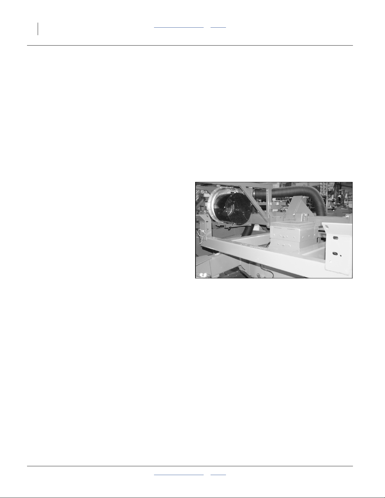
26 2- & 3-Section YP PTO Pumps Table of Contents Index Great Plains Manufacturing, Inc.
Models Not Listed
Single-section models 2025A, 2525A, YP425A,
YP425A3P, YP625A, YP625A3P, YP825A, YP825A3P
and YP825AR have separate 6-spline PTO kits, which
are covered in manual 401-885M.
®
For any other Air-Pro
Great Plains dealer contact the factory for current
information.
or Yield-Pro® planter, have your
Pre-Delivery and Other Options
If you are installing the Yield-Pro® PTO Pump on a
newly-shipped planter, it may be more convenient to
install the PTO pump system during the dealer
pre-delivery setup:
• Install the PTO pump system before mounting a seed
hopper or PROBOX® (or remove any seed container
present). This improves working space around the fan.
Exception: on models YP1630F, YP2425F and
YP4025F, install the seed structures first.
• Install the PTO pump system before installing or
completing installation of markers. This eliminates an
overhead sharp object hazard, and improves working
space at the fan(s).
• Install the PTO pump system after installing an
optional hydraulic tongue. Installing the tongue later
would require removing the PTO storage mount.
Prepare Planter
2. Read and understand “Important Safety
Information” starting on page 1.
3. Position the planter on a level surface in a well
lighted location suitable for the installation, which
includes room to unfold, and possibly room (and
vertical clearance) to unfold markers. A clear
surface beneath makes it easier to recover any
dropped parts.
4. Examine the working space around fans. If space is
tight, consider two steps to improve it:
a. dismount a removable seed hopper/PROBOX
b. unfold markers
5. Lower the unfolded planter, or install lift locks if left
raised.
6. Chock the tires if the surface is not completely level.
7. Unhitch the planter.
®
Figure 19:
YP2425: No Seed Hopper
26045
411-015M Table of Contents Index 2014-09-10
Page 31

Great Plains Manufacturing, Inc. Table of Contents Index Appendix A - Installation 27
Prepare Hitch
Disconnect Hose Fittings at Hitch
The existing fan hoses may be used to connect the new
PTO pump to hydraulic motors on the planter. The
hitch-end fittings are modified for this purpose.
Any other hydraulic motor circuits at the hitch, such as
hydraulic drive, are not re-used, and are left as-is at the
hitch end. They are capped at the rear ends.
Refer to Figure 20
Three fan hoses (supply, return and case drain) run from
the fan to the hitch. All fittings forward of the crimped-on
MORBs are removed. These hoses are later
1
re-connected to the pump or reservoir supplied with the
PTO kit.
Newer planters have a polymer hose handle on the fan
2
supply QD at the hitch. They may also have a handle on
the return line. Older planters do not have hose handles.
8. Set out an oil collection bucket near the hitch ends
of the hoses.
9. Remove any hose handle housings .
2
10. Disconnect the hoses from the hitch fittings at the
MORB connectors crimped on the hoses. Drain
1
the removed fittings and hose ends using the
bucket. Set the open hose ends in the bucket.
1
2
Figure 20:
36000
3-Port Fan Hoses
Install Pump Storage Mount
Storage mount installation varies by planter frame type.
Continue at the page for your kit, from the table below.
Kit Mount Location Go To Kit Mount Location Go To
401-934A
401-935A
401-936A
401-937A
401-938A
401-939A
401-940A
401-941A
401-942A
Tongue Storage Mount page 28
Tongue Storage Mount page 28
Tongue Storage Mount page 28
Tongue Storage Mount page 28
Tongue Storage Mount page 28
3PYP/A 3-Point Storage Mount page 28
3PYP/A 3-Point Storage Mount page 28
3PYP/A 3-Point Storage Mount page 28
3PYP/A 3-Point Storage Mount page 28
401-943A
401-944A
401-945A
401-946A
401-951A
411-014A
411-138A
411-147A
Tongue Storage Mount page 28
Tongue Storage Mount page 28
Tongue Storage Mount page 28
Tongue Storage Mount page 28
Tongue Storage Mount page 28
Tongue Storage Mount page 28
Tongue Storage Mount page 28
Tongue Storage Mount page 28
2014-09-10 Table of Contents Index 411-015M
Page 32

28 2- & 3-Section YP PTO Pumps Table of Contents Index Great Plains Manufacturing, Inc.
Tongue Storage Mount
This section applies only to pull-type planters. For 3PYP
and 3PYPA models see “3PYP/A 3-Point Storage
Mount” below.
B
U
L
Refer to Figure 21
11. Remove and save the nuts and washers on the
1
hitch bolts. Leave the bolts in place.
12. Inspect the orientation of the nuts and washers
on the hitch bolts. If the nuts are on the right side of
150
1
1
R
F
D
the hitch, continue at step 15.
13. Use a jack or hoist to slightly to raise either the
tongue or the hitch until one tongue bolt is loose.
Remove it from the right side of the tongue and
insert it from the left.
14. Adjust the jack or hoist to slightly to raise either the
tongue or the hitch until the other tongue bolt is
loose. Remove it from the right side of the tongue
and insert it from the left.
15. Select one new:
150
401-974H PTO PUMP STORAGE MNT
Place the mount on the exposed threads of the
Figure 21:
Tongue Storage Mount
36383
tongue bolts, with the mount lugs to the left and
forward. The tube is then oriented vertically, tipped
slightly to the rear at the top.
16. Secure the mount to with the saved washers and
nuts.
Continue at “Dismount Air Compressor(s)” on
page 29.
Roll-Away / Crushing Hazard:
Do not lift on an unlevel surface. The planter might shift or roll
away, resulting in serious injury or death, and substantial
equipment damage. If the planter is not parked on a
completely level surface, verify that the wheels are chocked to
prevent movement. The tongue jack or parking stand may be
the only resistance to motion.
3PYP/A 3-Point Storage Mount
This section applies only to 3PYP/A planters. For pulltype planters, see “Tongue Storage Mount” above.
Refer to Figure 22
17. Select one new:
158
401-982V 3PYP PTO PUMP STORAGE MNT
197
consisting of one:
157
401-981H 3PYP PTO PUMP MNT WLDMNT
and two sets:
197
802-041C HHCS 1/2-13X3 1/2 GR5
211
803-147C NUT HEX NYLOCK 1/2-13
Remove the fasteners.
18. Slide the mount weldment onto the right end of
157
157
the 3-point hitch tool bar. Loosely secure it with the
197 211
bolts and lock nuts . It is adjusted at step 88
on page 46.
Continue at “Prepare Fan(s)” on page 31.
Figure 22:
211
36384
3PYP/A 3-Point Storage Mount
411-015M Table of Contents Index 2014-09-10
Page 33

Great Plains Manufacturing, Inc. Table of Contents Index Appendix A - Installation 29
Dismount Air Compressor(s)
For models 3PYP and 3PYPA, continue at “Prepare
Fan(s)” on page 31.
For pull-type planters having no compressors, continue
at “Prepare Fan(s)” on page 31.
Refer to Figure 23 and Figure 24
Any air compressors at the tongue of a pull-type are
presently installed on their own pedestals , which
interfere with a PTO reservoir installation. The pedestals
are removed, and the compressors relocated to mounts
on the reservoir.
The needed reservoir mounts are separately purchased.
See page 6 for ordering information.
19. Remove protective housings at each compressor.
Save all parts and fasteners.
20. Locate a suitable disconnection point for each air
and electrical line near each compressor.
21. Label each tractor-side or implement-side hose or
lead as to which compressor it serves.
22. Disconnect the lines. Tape the air hoses or tie them
off to prevent ground contact or contamination.
23. Dismount each compressor assembly by removing
the fasteners that connect the base to the
pedestal platform. Save the assembly and all
fasteners.
24. At each lower U-bolt, dismount the pedestal from
the tongue. The pedestal, U-bolt, U-bolt washers
and U-bolt nuts are not re-used.
Each compressor is re-installed on a new mount at a
later step.
1
2
Figure 23:
Row-Pro™ Compressor
2
1
34090
2
1
Figure 24:
Swath Command™ Compressor
2014-09-10 Table of Contents Index 411-015M
34090
Page 34

30 2- & 3-Section YP PTO Pumps Table of Contents Index Great Plains Manufacturing, Inc.
Verify Reservoir Mount Holes
For models 3PYP and 3PYPA, continue at “Prepare
Fan(s)” on page 31.
Planters manufactured in 2012 and earlier need to have
PTO oil reservoir mount holes added to the hitch side
plates.
Refer to Figure 25, Figure 26 or Figure 27,
showing left hand plates - the RH side is mirror image
25. Inspect both hitch side plates for two sets of
14.9 mm (9⁄16inch) through-holes above and to the
rear of the hitch height adjustment holes.
720 mm
28.34 in.
28 11/32 in.
642 mm
25.27 in.
25 17/64 in.
Ø (2 plc.)
14.3 mm
42 mm
1.64 in.
1 41/64 in.
9/16 in.
0.56 in.
If the holes are present, continue at “Prepare
Fan(s)” on page 31.
Drill Mount Holes
26. Mark hole locations on each side of the hitch. The
lateral location is relative to the vertical center-line
of the hitch adjustment holes. The vertical location
is relative to a horizontal edge that varies by tongue
style.
27. Drill pilot holes, then finish holes.
121 mm
4.76 in.
Ø (2 plc.)
14.3 mm
9/16 in.
0.56 in.
491 mm
19.34 in.
19 11/32 in.
384 mm
15.13 in.
15 1/8 in.
134 mm
5 17/64 in.
720 mm
28.34 in.
28 11/32 in.
613 mm
24.13 in.
24 1/8 in.
148 mm
5.85 in.
5 27/32 in.
Figure 25: PTO Mount Holes:
YP4425A
212 mm
8.34 in.
8 11/32 in.
5.26 in.
36323
Ø (2 plc.)
14.3 mm
9/16 in.
0.56 in.
Figure 26: PTO Mount Holes:
YP12, YP16, YP30, YP40
411-015M Table of Contents Index 2014-09-10
36321
Figure 27: PTO Mount Holes:
YP2425/A/F
36322
Page 35

Great Plains Manufacturing, Inc. Table of Contents Index Appendix A - Installation 31
Prepare Fan(s)
Note: Kit 411-014A for model YP2425F includes two fan
coolers. Perform the cooler installation for each fan.
3
Open Fan Screen
Refer to Figure 28 (fan exit port orientation varies by planter
model and fan location/function)
28. Remove and save the sheet metal screws
securing the cap to the screen .
29. Remove and save the screen cap .
2 3
2
Identify Fan Type
Cooler installation steps are different for 6-inch and
8-inch fans.
Refer to Figure 29
6-Inch Fan
6-inch fans have 6 screws securing the cage (and any
sensor bracket) to the fan housing. 6-inch fans take
cooler bundles:
124
401-143L 6IN HYD FAN COOLER 7/8MJIC or
125
401-833L 6IN HYD FAN COOLER ASSY
For a 6-inch fan, continue at “6in: Relocate Sensor
Bracket” on page 32.
8-Inch Fan
8-inch fans have 4 screws securing the cage (and any
sensor bracket) to the fan housing. 8-inch fans take
cooler bundles:
127
401-924L 8IN FAN COOLER ASSY 3/4MJIC or
128
401-926L 8IN FAN COOLER ASSY 7/8MJIC
For an 8-inch fan, continue at “Install 8-Inch Fan
Cooler” on page 36.
Cooler Installation Page Reference
Kit Description Fan Page Kit Description Fan Page
401-934A YP12,16 HYD DRV PTO KIT 6 in. 32 411-147A YP16AHD PTO KIT 6 in. 32
401-936A YP12,16 GRND DRV PTO KIT 6 in. 32 401-935A YP12A,16A HYD DRV PTO KIT 8 in. 36
401-938A YP16F PTO KIT 6 in. 32 401-937A YP12A,16A GRND DRV PTO KIT 8 in. 36
401-939A 3PYP HYD DRV PTO KIT 6 in. 32 401-940A 3PYPA HYD DRV PTO KIT 8 in. 36
401-941A 3PYP GRND DRV PTO KIT 6 in. 32 401-942A 3PYPA GRND DRV PTO KIT 8 in. 36
401-943A YP24 PTO KIT 6 in. 32 401-944A YP24A PTO KIT 8 in. 36
401-945A YP30,40 PTO KIT 6 in. 32 401-946A YP30A,40A PTO KIT 8 in. 36
411-014A YP24F PTO HYDRAULIC PUMP KIT 6 in. 32 401-951A YP44A PTO KIT 8 in. 36
411-138A YP16AHL PTO KIT 6 in. 32
1
1
Figure 28:
Open Fan Screen
Figure 29:
6- and 8-Inch fans
36003
36378
2
2014-09-10 Table of Contents Index 411-015M
Page 36

32 2- & 3-Section YP PTO Pumps Table of Contents Index Great Plains Manufacturing, Inc.
6in: Relocate Sensor Bracket
This page applies only to 6-inch/6-cage-screw fans.
For 8-inch fans, continue page 36.
Refer to Figure 30 (top and bottom are relative to Up and
Down, and not to the fan exit port, often not at top)
30. Inspect the fan cage for presence of a:
17
401-537D DJ FAN SENSOR MOUNT BRKT
The bracket may or may not have a sensor installed.
If there is no sensor bracket, skip to step 33.
If the bracket is installed in the top and bottom
a
holes , skip to step 33.
If the bracket is not in the top-most and bottom-most
holes, it must be relocated.
Refer to Figure 31 (top and bottom are relative to Up and
Down, and not to the fan exit port, often not at top)
31. This step presumes that there is a sensor
bracket , and it is mounted in one of the lateral
holes sets . Remove and save two sets of
fasteners securing the bracket, and two sets of
fasteners at the top and bottom holes , four sets
total.
Note: Leave the final set of lateral fasteners in place,
32. Relocate the sensor bracket to a vertical
orientation, using hole set . Secure it with two sets
of saved fasteners.
33. Remove and save the four or remaining two sets of
fasteners at lateral holes . These holes are used
for mounting the cooler in the following steps.
34. Repeat step 28 through step 33 for all hydraulic fans
on the planter.
Continue at “6in: Install Fan Cooler(s)” on page 33
17
b
4
4 a
5
so that the fan cage does not need to be
re-mounted.
17
a
5
17
U
D
a
17
b
b
U
a
OK
Inspect Sensor Bracket
D
Figure 30:
Relocate
36004
a
17
b
4
5
Figure 31:
Relocate Sensor Bracket
36005
411-015M Table of Contents Index 2014-09-10
Page 37

Great Plains Manufacturing, Inc. Table of Contents Index Appendix A - Installation 33
6in: Install Fan Cooler(s)
This page applies only to 6-inch/6-cage-screw fans.
For 8-inch fans, continue page 36.
Refer to Figure 32
In normal use, the hydraulic fan circuit requires enough
power that, absent a tractor oil radiator or local cooler,
the oil would overheat. The Yield-Pro
®
PTO pump kit
includes one or more cooler (radiator)
assemblies ( or ) that install inside the fan
124 125
cage(s).
Note: Do not disconnect the fan motor hoses during
cooler installation. Those hoses are reconnected
during “Install Hoses” on page 49.
4
124
125
6in: Install Cooler
6-Inch Fan: Break Down Cooler Assembly
Refer to Figure 33
The cooler assembly ( or ) must be partially
disassembled to have access to the shroud mounting
holes.
35. Select one new of:
124
401-143L 6IN HYD FAN COOLER 7/8MJIC
125
401-833L 6IN HYD FAN COOLER ASSY
Remove and save four:
201
802-159C HHCS 5/16-18X1 GR5
Leave the nut clips on the shroud ( or ).
Separate the shroud and cooler :
126
401-834H 6 IN HYD FAN SHROUD
221
810-804C C12 HYD OIL COOLER
6in: Install Cooler Shroud
Refer to Figure 34 (shown with fan cage dismounted for
clarity of bolt hole assignment - the cage should already be
secured via top and bottom holes)
36. Select one of new:
126
401-834H 6 IN HYD FAN SHROUD
and four sets saved fasteners .
Attach the shroud through the fan cage holes, to the
fan housing, using the saved fasteners.
124 125
192 126 136
126 221
4
201
Figure 32:
6 in. Fan Cooler Arrangement
192
Figure 33:
Break Down Cooler
36376
221
126
34632
126
4
Figure 34:
36376
Install Cooler Shroud
2014-09-10 Table of Contents Index 411-015M
Page 38

34 2- & 3-Section YP PTO Pumps Table of Contents Index Great Plains Manufacturing, Inc.
6in: Orient Cooler Elbows
This page applies only to 6-inch/6-cage-screw fans.
For 8-inch fans, continue page 36.
221
Refer to Figure 35
37. Set the fan cooler horizontally on a work
surface (mounting holes at top and bottom). This is
the orientation of the cooler after final installation.
Loosen the jam nuts of the elbow fittings . Rotate
221
50°
to
6
60°
6
the inlet JIC ends to point at the angles shown.
When installed in the fan cage, these orientations
point roughly at top center and bottom center of the
cage.
Tighten the jam nuts (see page 86 for fitting torque).
6in: Re-Assemble Fan Cooler
Refer to Figure 36
38. Select the cooler:
221
810-804C C12 HYD OIL COOLER
and four sets saved:
201
802-159C HHCS 5/16-18X1 GR5
With the elbow fittings toward the cap end of the fan,
use the bolts to re-attach the fan cooler (
223 126 192
or ) to the shroud at the nut clips .
201 221
6in: Modify Fan Cage
Refer to Figure 37
39. Prepare an exit opening in the fan cage for the
cooler hoses. The hole needs to be:
• located at bottom center of the fan cage,
• on the center-line of the MJIC elbow ports,
• wide enough for a 3/4 FJIC hose fitting, about:
3.2 cm (11⁄4inches)
a
• long enough for one hose diameter plus one
3/4 FJIC or 7/8 FJIC hose fitting, about
5.7 cm (21⁄4inches)a total, and
• have a smooth edge. Making cuts (- - -) as
shown, and folding back the cage edges, to the
inside, provides an adequately smooth edge.
192
Figure 35:
6in: Orient Elbows
126
Figure 36:
Re-Assemble Cooler
34635
221
201
36376
a. For assembly 401-143L, with 7/8 JIC hose ends, use
3.8 cm (1
1
⁄2inches) wide, 6.4 cm (21⁄2inches) long
Note: If an existing rpm sensor lead hole is present, and
at a suitable location, enlarge it for hose use.
Figure 37:
6in: Hose Opening in Cage
411-015M Table of Contents Index 2014-09-10
Page 39

Great Plains Manufacturing, Inc. Table of Contents Index Appendix A - Installation 35
6in Fan: Attach Cooler Hoses & Close
This page applies only to 6-inch/6-cage-screw fans.
For 8-inch fans, continue page 36.
6in Fan: Cooler Inlet Hose
Note: Model YP2425F (kit 411-014A) has two coolers.
Inlet and outlet hoses are different for each cooler.
Fan#1 is the forward fan.
INLET
u
Fan#2 is the rear fan.
Refer to Figure 38
40. Select one new cooler inlet hose from the table
n
OUTLET
below (hose is kit dependent).
41. Route the hose through the hole prepared at
n
step 39. Connect it to the upper fitting on the cooler.
42. Mark the free end of this hose “INLET”. This step is
particularly important for kits using identical inlet
and outlet hoses and/or for short hoses which may
not be marked with a part number at both ends.
43. Select one new cooler outlet hose from the
u
Figure 38:
Cooler Hoses
34636
table below (hose is kit dependent).
Route the hose through the hole prepared at
step 39. Connect it to the lower fitting on the cooler.
44. Mark the free end of this hose “OUTLET”.
1
3
Note: The external ends of these hoses are not
connected at this time.
2
6in: Reinstall Fan Cap
Refer to Figure 39
45. Position the saved fan screen cap on the fan
screen , aligning existing screw holes. Secure cap
3
to screen with saved sheet metal screws .
2
1
Figure 39:
Close Fan Cage
34631
46. Continue at “Install Oil Reservoir” on page 39.
6in Fan Hose Reference
Kit Fan Cooler Inlet Hose Kit Fan Outlet Hose
401-934A -
401-936A -
401-938A -
401-939A -
401-941A -
401-943A -
401-945A -
411-014A 1
411-138A -
411-147A -
263
841-196C HH1/2R2 024 3/4FJIC
263
841-196C HH1/2R2 024 3/4FJIC
242
811-279C HH1/2R2 060 3/4FJIC
241 264
811-269C HH1/2R2 036 3/4FJIC
241 250
811-269C HH1/2R2 036 3/4FJIC
263 272
841-196C HH1/2R2 024 3/4FJIC
243
811-291C HH1/2R2 072 3/4FJIC
240 240
811-268C HH1/2R2 048 3/4FJIC
connected to fan outlet tee later
240 272
2
811-268C HH1/2R2 048 3/4FJIC
from cooler #1
283
841-921C HH5/8R2 032 7/8FJIC
296
851-345C HH5/8R2 060 7/8FJIC
n
401-934A -
401-936A -
401-938A -
401-939A -
401-941A -
401-943A -
401-945A -
411-014A 1
411-138A -
411-147A -
Existing fan return hose at fan.
Existing fan return hose at fan.
Existing fan return hose at fan.
841-249C HH1/2R2 108 3/4FJIC
811-665C HH1/2R2 208 3/4FJIC
841-506C HH1/2R2 030 3/4MJIC
3/4FJIC
Existing fan return hose at fan.
811-268C HH1/2R2 048 3/4FJIC
to cooler #2
2
841-506C HH1/2R2 030 3/4MJIC
3/4FJIC
Existing fan return hose at fan.
Existing fan return hose at fan.
u
2014-09-10 Table of Contents Index 411-015M
Page 40

36 2- & 3-Section YP PTO Pumps Table of Contents Index Great Plains Manufacturing, Inc.
Install 8-Inch Fan Cooler
This page applies only to 8-inch/4-cage-screw fans.
For 6-inch fans, see page 32.
8in: Dismount Screen Assembly
Refer to Figure 40 (the fan screen extension is not
present at dismount and is added at step 66 on page 38)
8in: Remove Screen Cap and Rain Cover
47. Remove and save all fasteners ( and , not all
shown) securing the cap and rain cover to the
screen .
Note: The cap and cover screws are different sizes.
48. Remove and save the screen cap, rain cover and
screws.
8in: Dismount Sensor
Note which two holes are used for the sensor bracket,
and which two only for the fan screen.
49. Disconnect the sensor lead outside the fan screen.
50. Remove and save two sets of fasteners securing
the sensor bracket to the fan housing.
51. Remove and save the sensor assembly.
8in: Dismount Fan Screen
Note: The fan housing and fan screen are eccentric in
52. Make an alignment mark on the fan screen and on
the fan housing, to indicate factory alignment. Or
take a photograph for reference.
53. Loosen or remove the last two sets of fasteners
securing the fan screen to the fan housing.
8in: Break Down Cooler Assembly
Note: The shroud cannot be installed with the
54. Remove and save four sets of:
210
Separate the cooler from the shroud .
8in: Install Screen and Shroud
Note: It may be easier to use two saved screws, without
3
shape. Although the four mounting holes may line
up in various orientations of the screen, only one
orientation is correct.
136
cooler mounted.
washers, at the sensor bracket locations to
temporarily hold the fan screen and shroud
in place while seated the screws and washers at
the other two fan housing holes.
223
803-043C NUT HEX WHIZ 5/16-18 PLT
253
223 136
190
127
4
3 136
27
3
53
127
128
2
136
1
19
4
223
210
190
Figure 40:
8 in. Fan Cooler Arrangement
55. Select the shroud:
136
401-958H 8IN FAN HYD OIL COOLER
the saved fan screen and
two sets saved fasteners .
Align the fan screen as marked or shown in your
photo. Place the shroud inside the screen, with the
cutaway corner on the bottom and facing away from
the fan outlet. Loosely secure both to the fan
housing using the saved fasteners.
8in: Install Sensor Bracket
56. Re-install the sensor bracket using two sets of
saved fasteners. Fully tighten all four sets of
fasteners securing the screen and bracket to the fan
housing.
8in: Adjust Sensor Gap
Note: The re-installed sensor is now further away from
the fan hub than prior to kit installation. The
sensor gap must be reset.
57. Loosen the jam nuts on the sensor. Check for axial
play on the fan hub; if there is any, pull the hub
toward the sensor. Screw the sensor toward the hub
until contact. Back off one turn. Check clearance.
Secure jam nuts.
3
4
36377
411-015M Table of Contents Index 2014-09-10
Page 41

Great Plains Manufacturing, Inc. Table of Contents Index Appendix A - Installation 37
8in: Orient Cooler Elbows
Refer to Figure 41
58. Set the fan cooler horizontally on a work
223
223
surface (mounting holes at top and bottom). This is
the orientation of the cooler after final installation.
Loosen the jam nuts of the elbow fittings . Rotate
6
the inlet JIC ends to point at the angles shown.
When installed in the fan cage, these orientations
point roughly at top center and bottom center of the
cage.
Tighten the jam nuts (see page 86 for fitting torque).
8in: Install Cooler Hoses
Refer to Figure 42
59. Select one new cooler inlet hose from the table
n
below (hose is kit dependent).
60. Mark the free end of this hose “INLET”. This step is
particularly important for kits using identical inlet
and outlet hoses and/or for short hoses which may
not be marked with a part number at both ends.
61. Select one new cooler outlet hose from the
u
table below (hose is kit dependent).
62. Mark the free end of this hose “OUTLET”.
Note: The external ends of these hoses are not
connected at this time.
INLET
n
50°
to
60°
Figure 41:
8in: Orient Elbows
u
Figure 42:
8in: Connect Hoses
6
36379
223
6
OUTLET
36379
8in Fan Hose Reference
Kit Cooler Inlet Hose Kit Outlet Hose
401-935A 811-268C HH1/2R2 048 3/4FJIC 401-935A
401-937A 811-268C HH1/2R2 048 3/4FJIC 401-937A
401-940A 811-268C HH1/2R2 048 3/4FJIC 401-940A
401-942A 811-268C HH1/2R2 048 3/4FJIC 401-942A
401-944A 841-921C HH5/8R2 032 7/8FJIC 401-944A
401-946A 811-268C HH1/2R2 048 3/4FJIC 401-946A
401-951A 811-268C HH1/2R2 048 3/4FJIC 401-951A
2014-09-10 Table of Contents Index 411-015M
240
240
240
240
283
240
240
n u
272
841-506C HH1/2R2 030 3/4MJIC 3/4FJIC
272
841-506C HH1/2R2 030 3/4MJIC 3/4FJIC
240
811-268C HH1/2R2 048 3/4FJIC
240
811-268C HH1/2R2 048 3/4FJIC
63
841-334C HH5/8R2 312 7/8FJIC
272
841-506C HH1/2R2 030 3/4MJIC 3/4FJIC
272
841-506C HH1/2R2 030 3/4MJIC 3/4FJIC
Page 42

38 2- & 3-Section YP PTO Pumps Table of Contents Index Great Plains Manufacturing, Inc.
8in: Modify Fan Cage
Refer to Figure 43
63. Prepare an exit opening in the fan cage for the
cooler hoses. The hole needs to be:
• located at bottom center of the fan cage,
• on the center-line of the MJIC elbow ports,
• wide enough for a 3/4 FJIC hose fitting, about:
3.2 cm (11⁄4inches)
a
• long enough for one hose diameter plus one
3/4 FJIC or 7/8 FJIC hose fitting, about
5.7 cm (2
1
⁄4inches)a total, and
• have a smooth edge. Making cuts (- - -) as
shown, and folding back the cage edges, to the
inside, provides an adequately smooth edge.
a. For assembly 401-143L, with 7/8 JIC hose ends, use
3.8 cm (1
1
⁄2inches) wide, 6.4 cm (21⁄2inches) long
Note: If an existing rpm sensor lead hole is present, and
at a suitable location, enlarge it for hose use.
8in: Install Cooler
64. Route the cooler hoses through the hole prepared
at step 63.
Refer to Figure 44
65. With the elbows toward the cooler shroud, position
the cooler on the threaded studs of the cooler
223
shroud. Secure with 4 whiz nuts:
210
803-043C NUT HEX WHIZ 5/16-18 PLT
8in: Install Screen Extension
66. Select one new:
190
421-615D CRARY 8IN FAN SCREEN EXT
and eight saved screws originally used to secure
the screen cap to the screen. Secure the extension
to the screen using the saved screws.
8in: Install Screen Cap
67. Select the saved screen cap and eight new:
205
802-800C HWH #12-14X3/4
2
Secure the cap to the screen extension by creating
new holes from the face of the screen.
Figure 43:
8in: Hose Opening in Cage
223
210
190
Figure 44:
8 in. Fan Cooler Install
2
205
36377
411-015M Table of Contents Index 2014-09-10
Page 43

Great Plains Manufacturing, Inc. Table of Contents Index Appendix A - Installation 39
Install Oil Reservoir
Determine Reservoir Location
Refer to Figure 45
68. Determine the reservoir mounting location based on
the kit:
Kit Location Go To
401-934A
401-935A
401-936A
401-937A
401-938A
401-939A
401-940A
401-941A
401-942A
401-943A
401-944A
401-945A
401-946A
401-951A
411-014A
411-138A
411-147A
1
Tongue below
1
Tongue below
1
Tongue below
1
Tongue below
1
Tongue below
2
Mainframe page 40
2
Mainframe page 40
2
Mainframe page 40
2
Mainframe page 40
1
Tongue below
1
Tongue below
1
Tongue below
1
Tongue below
1
Tongue below
1
Tongue below
1
Tongue below
1
Tongue below
Reservoir on Tongue
These instructions apply to pull-type planters. For other
configurations see page referenced from table above.
The tongue location is used with pull-type planters,
having either the standard 3-point hitch or the optional
hydraulic hitch.
69. Select the reservoir, one of:
146
401-970L YP30,40 HYD RES ASSY
147
401-971L YP12,16,44 HYD RES ASSY
149
401-973L YP24A YD RES ASSY
and four sets new:
199
802-128C HHCS 1/2-13X2 GR5
216
804-016C WASHER FLAT 1/2 SAE PLT
215
804-015C WASHER LOCK SPRING 1/2 PLT
209
803-020C NUT HEX 1/2-13 PLT
WARNING
HOT FLUID HAZARD
Read Owner’s Manual BEFORE operating machine.
Keep tractor at IDLING SPEED an
to prevent dama
Keep Radiator clean and free of foreign matter to
prevent overheating.
ge to Hydrau
Do NOT operate with hydraulic oil at or above 180°F.
d slowly engage PTO
lic Motor
858-004C
209
OIL FILL LINE
CAPACITY = 13.5 U.S. GALS
USE ANY HIGH QUALITY MINERAL BASED
HYDRAULIC FLUID WITH A VISCO
OF 10W-30. OIL MUST BE CLEAN AND FREE
FROM DIRT OR CONTAMINANT PARTICLES TO
PREVENT DAMAGE TO PUMP AND MOTOR.
REPLACE FILTER ELEMENT AFTER EVERY
150 OPERATING HOURS OR 2 YEARS SERVICE.
LEVEL TOOLBAR BEFORE C
SITY RATING
H
EKING OIL LEVEL
CAUTION
To avoid Injury or
858-029C
Machine Damage:
·Operate only with
1000 rpm PTO
818-240
C
Rev. A
215
DANGER
ROTATING DRIVELINE -
CONTACT CAN CAUSE DEATH
KEEP AWAY!
DO NOT OPERATE WITHOUT-
All driveline guards, tractor
and equipment shields in place
PTO pump assembly securely
attached with torque arm and clamp
bolts properly torqued
858030C
216
1
Figure 45:
Reservoir Locations
WARNING
HOT FLUID HAZARD
Read Owner’s Manual BEFORE operating machine.
Keep tractor at IDLING SPEED and slowly engage PTO
to prevent damage to Hydraulic Motor
Keep Radiator clean and free of foreign matter to
prevent overheating.
OIL FILL LINE
Do NOT operate with hydraulic oil at o
CAPACITY = 13.5 U.S. GALS
USE ANY HIGH QUALITY MINERAL BASED
HYDRAULIC FLUID WITH A VISCOSITY RATING
OF 10W-30. OIL MUST BE CLEAN AND FREE
r above 180°F.
FROM DIRT OR CONTAMINANT PARTICLES TO
PREVENT DAMAGE TO PUMP AND MOTOR.
REPLACE FILTER ELEMENT AFTER EVERY
8
58-004C
150 OPERATING HOURS OR 2 YEARS SERVICE.
LEVEL TOOLBAR
BEFORE CHEKING OIL LEVEL
CAUTION
858-029C
To avoid Injury or
Machine Damage:
·Operate only with
1000 rpm PTO
DANGER
818-240C Rev. A
ROTATING DRIVELINE -
CONTACT CAN CAUSE DEATH
KEEP AWAY!
DO NOT OPERATE WITHOUT-
All driveline guards, tractor
and equipment shields in place
PTO pump assembly securely
attached with torque arm and clamp
bolts properly torqued
858-030C
199
OIL FILL LINE
CAPACITY = 13.5 U.S. GALS
USE ANY HIGH QUALITY MINERAL BASED
HYDRAULIC FLUID WITH A VISCOSITY RATING
OF 10W-30. OIL MUST BE CLEAN AND FREE
FROM DIRT OR CONTAMINANT PARTICLES TO
PREVENT DAMAGE TO PUMP AND MOTOR.
REPLACE FILTER ELEMENT AFTER EVERY
150 OPERATING HOURS OR 2 YEARS SERVICE.
LEVEL TOOLBAR BEFORE CHEKING OIL LEVEL
146
147
149
HOT FLUID HAZARD
Read Owner’s Manual BEFORE operating machine.
Keep tractor at IDLING SPEED and slowly engage PTO
to prevent damage to Hydraulic Motor
029C
858-
Keep Radiator clean and free of foreign matter to
prevent overheating.
Do NOT operate with hydraulic oil at or above 180°F.
WARNING
858-004C
34843
36380
2
Secure the reservoir, sight gauge side forward to
the tongue using any four of the six bolt holes in the
lower weldments.
Continue at “Reinstall Compressor(s)” on page 41.
Figure 46:
36382
Install Reservoir on Tongue
2014-09-10 Table of Contents Index 411-015M
Page 44

40 2- & 3-Section YP PTO Pumps Table of Contents Index Great Plains Manufacturing, Inc.
Reservoir on Mainframe
These instructions apply only to kits 401-939A,
401-940A, 401-941A and 401-942A for planter models
3PYP and 3PYPA. For other kits see the page director
table on page 39.
Refer to Figure 47
70. Select one new:
148
401-972L 3PYP PTO TANK ASSY
and two sets new:
203
802-269C HHCS 1/2-13X9 GR5
211
803-147C NUT HEX NYLOCK 1/2-13
71. Remove any lock channel (not shown) presently
pinned to the left rear outside of the mainframe.
72. With the decal face of the reservoir facing left, slide
the reservoir mount weldment fully right and fully
forward at the left rear corner of the mainframe.
Secure with bolts and lock nuts .
203 211
73. Re-pin any removed lock channel.
Continue at “Install Flow Control Valve” on page 43.
211
OIL FILL LINE
CAPACITY = 13.5 U.S. GALS
USE ANY HIGH QUALITY MINERAL BASED
HYDRAULIC FLUID WITH A VISCOSITY RATING
OF 10W-30. OIL MUST BE CLEAN AND FREE
FROM DIRT OR CONTAMINANT PARTICLES TO
PREVENT DAMAGE TO PUMP AND MOTOR.
REPLACE FILTER ELEMENT AFTER EVERY
150 OPERATING HOURS OR 2 YEARS SERVICE.
LEVEL TOOLBAR BEFORE CHEKING OIL LEVEL
WARNING
HOT FLUID HAZARD
Read Owner’s Manual BEFORE operating machine.
Keep tractor at IDLING SPEED and slowly engage PTO
to prevent damage to Hydraulic Motor
858-029C
Keep Radiator clean and free of foreign matter to
prevent overheating.
Do NOT operate with hydraulic oil at or above 180°F.
148
858-004C
203
Figure 47:
Install 3PYP/A Reservoir
36381
411-015M Table of Contents Index 2014-09-10
Page 45

Great Plains Manufacturing, Inc. Table of Contents Index Appendix A - Installation 41
GER
Reinstall Compressor(s)
This topic applies only to pull-type planters with tonguemounted compressors used for Row-Pro™ or Swath
Command™. The compressor(s) were removed at
“Dismount Air Compressor(s)” on page 29. If no
compressors were dismounted, continue at “Install Flow
Control Valve” on page 43.
Compressor Install Page
Kit Kit Description Go To
411-183A
First or only compressor, on
Reservoir top, all models
page 41
Second compressor, models:
411-184A
1625AHD/L, YP1220,
page 42
YP1225/A, YP1625/A
Second compressor, models:
411-185A
YP2425/A/F, YP3010HDP,
YP3025/A, YP4010HDP,
page 42
YP4025/A/F
Install First or Only Compressor
This applies to compressor relocation kit:
411-183A PTO AIR COMP MNT ASSEMBLY
For other kits, see the page director table on page 41.
Refer to Figure 49
74. Select one new:
187
421-173D PTO TANK AIR COMP MNT PLT
and four sets new:
195
802-017C HHCS 3/8-16X1 GR5
214
804-013C WASHER LOCK SPRING 3/8 PLT
208
803-014C NUT HEX 3/8-16 PLT
WARNING
HOT FLUID HAZARD
Read Owner’s Manual BEFORE operating machine.
Keep tractor at IDLING SPEED and slowly engage PTO
to prevent damage to Hydraulic Motor
Keep Radiator clean and free of foreign matter to
prevent overheating.
Do NOT operate with hydraulic oil at or above 180°F.
195
OIL FILL LINE
CAPACITY = 13.5 U.S. GALS
USE ANY HIGH QUALITY MINERAL BASED
HYDRAULIC FLUID WITH A VISCOSITY RATING
OF 10W-30. OIL MUST BE CLEAN AND FREE
FROM DIRT OR CONTAMINANT PARTICLES TO
PREVENT DAMAGE TO PUMP AND MOTOR.
REPLACE FILTER ELEMENT AFTER EVERY
858-004C
150 OPERATING HOURS OR 2 YEARS SERVICE.
LEVEL TOOLBAR BEFORE CHEKING OIL LEVEL
CAUTION
To avoid Injury or
858-029C
Machine Damage:
·Operate only with
1000 rpm PTO
818-240C Rev. A
DANGER
ROTATING DRIVELINE -
CONTACT CAN CAUSE DEATH
KEEP AWAY!
DO NOT OPERATE WITHOUT-
All driveline guards, tractor
and equipment shields in place
PTO pump assembly securely
attached with torque arm and clamp
bolts properly torqued
Figure 48:
Compressor Re-installed
187
858-030C
36387
U
R
F
B
L
D
With the mounting holes to reservoir front, secure
the mount plate to the mount tabs on the
reservoir, using the bolts , lock washers and
208
nuts .
75. (not shown) Reinstall the compressor and its
housing, using the saved fasteners.
Continue at “Install Flow Control Valve” on page 43.
187
195 214
214
208
WARNING
HOT FLUID HAZARD
Read Owner’s Manual BEFORE operating machine.
Keep tractor at IDLING SPEED and slowly engage PTO
to prevent damage to Hydraulic Motor
Keep Radiator clean and free of foreign matter to
prevent overheating.
Do NOT operate with hydraulic oil at or above 180°F.
858-004C
OIL FILL LINE
CAPACITY = 13.5 U.S. GALS
USE ANY HIGH QUALITY MINERAL BASED
HYDRAULIC FLUID WITH A VISCOSITY RATING
OF 10W-30. OIL MUST BE CLEAN AND FREE
FROM DIRT OR CONTAMINANT PARTICLES TO
PREVENT DAMAGE TO PUMP AND MOTOR.
REPLACE FILTER ELEMENT AFTER EVERY
150 OPERATING HOURS OR 2 YEARS SERVICE.
LEVEL TOOLBAR BEFORE CHEKING OIL LEVEL
CAUTION
To avoid Injury or
858-029C
Machine Damage:
·Operate only with
1000 rpm PTO
818-240C Rev. A
Figure 49:
DAN
36386
Install 411-183A Mount
2014-09-10 Table of Contents Index 411-015M
Page 46

42 2- & 3-Section YP PTO Pumps Table of Contents Index Great Plains Manufacturing, Inc.
Second Compressor, 1625AH, YP12/16
This applies to compressor relocation kit:
411-184A YP12/16 2ND PTO AIR COMP MNT
For other kits, see the page director table on page 41.
Refer to Figure 50
76. Select one new:
135
401-957H AIR COMPRESSOR MNT WIDE
and four sets new:
195
802-017C HHCS 3/8-16X1 GR5
214
804-013C WASHER LOCK SPRING 3/8 PLT
208
803-014C NUT HEX 3/8-16 PLT
With the platform to reservoir rear, secure the
mount to the upper holes off the reservoir
supports, using the bolts , lock washers and
nuts .
77. (not shown) Reinstall the compressor and its
housing, using the saved fasteners.
135
195 214
208
B
U
135
R
195
214
208
Second Compressor, YP24/30/40/44
This applies to compressor relocation kit:
411-185A YP30,40,44,24 2ND PTO AIR COMP
For other kits, see the page director table on page 41.
Refer to Figure 50
78. Select one new:
140
401-962H YP30,40,24 AIR COMP TANK MNT
and four sets new:
195
802-017C HHCS 3/8-16X1 GR5
214
804-013C WASHER LOCK SPRING 3/8 PLT
208
803-014C NUT HEX 3/8-16 PLT
With the platform to reservoir rear, secure the
mount to the rear holes off the reservoir tabs,
using the bolts , lock washers and nuts .
79. (not shown) Reinstall the compressor and its
housing, using the saved fasteners.
140
195 214 208
L
140
D
L
B
F
Figure 50:
Install 411-184A Mount
U
F
R
D
36388
214
208
195
Figure 51:
Install 411-184A Mount
411-015M Table of Contents Index 2014-09-10
36389
Page 47

Great Plains Manufacturing, Inc. Table of Contents Index Appendix A - Installation 43
Install Flow Control Valve
When powered by PTO, the primary control of fan speed
is the flow control valve, normally located near the fan or
fans.
Determine Control Location
Control valve location varies principally by planter
mainframe structure and fan location. There are eight
locations for the presently available kits. Continue on the
page for your kit, per the page director table below.
Flow Control Install Page
Kit Valve Location Go To
401-934A
401-935A
401-936A
401-937A
401-938A
401-939A
401-940A
401-941A
401-942A
401-943A
401-944A
401-945A
401-946A
401-951A
411-014A
411-138A
411-147A
Arch Frame Cross Tube page 44
Fan Manifold page 45
Arch Frame Cross Tube page 44
Fan Manifold page 45
Rear Walkboard page 45
3-Point Hitch page 46
3-Point Hitch page 46
3-Point Hitch page 46
3-Point Hitch page 46
Center Walkboard page 46
Center Walkboard page 46
Mainframe LH page 47
Fan Mast page 47
Fan Mast page 47
Center Walkboard page 46
Cart Strut page 48
Rear Walkboard page 45
Figure 52:
Flow Control Valve Installed
at Fan Manifold
34843
2014-09-10 Table of Contents Index 411-015M
Page 48

44 2- & 3-Section YP PTO Pumps Table of Contents Index Great Plains Manufacturing, Inc.
Valve on Arch Frame
This location applies to kits 401-934A and 401-936A, for
models YP1220, YP1225 and YP1625. For other
kits/models, see the page director table on page 43.
Refer to Figure 53 (the valve assembly is shown exploded for
clarity - the valve and mount plate are pre-assembled)
80. On the right end of the rear-most cross tube of the
arch frame, locate the tab supporting the seed tube
support bracket weldment (not shown). Remove
and save two sets:
28
803-014C NUT HEX 3/8-16 PLT
35
804-013C WASHER LOCK SPRING 3/8 PLT
34
804-012C WASHER FLAT 3/8 SAE PLT
81. Remove the upper existing bolt:
23
802-079C HHCS 3/8-16X1 1/4 GR5
Leave the lower bolt in to support the seed tube
bracket. Existing bolt is not reused.
23
82. Select one of new:
151
401-975L YP12,16 HYD DRV FLOW CNTRL
152
401-976L YP12,16 GRND DRV FLOW CNTRL
and one new:
196
802-022C HHCS 3/8-16X1 1/2 GR5
Insert the new bolt through the upper break
196
hole of the valve mount plate, and then into the
upper tab hole and support bracket. Loosely secure
with one set of save flat washer , lock washer
and nut .
28
83. Remove the lower existing bolt . Select one new:
196
802-022C HHCS 3/8-16X1 1/2 GR5
Insert the new bolt through the lower break hole
196
34 35
23
of the valve mount plate, and then into the lower tab
hole and support bracket. Secure both new bolts
with the saved flat washers , lock washers and
28
nuts .
34 35
Continue at “Install Hoses” on page 49.
196
151
152
23
34
Figure 53:
Valve Installation at Arch Frame
L
B
U
F
R
D
35
28
36390
411-015M Table of Contents Index 2014-09-10
Page 49

Great Plains Manufacturing, Inc. Table of Contents Index Appendix A - Installation 45
Valve on Fan Manifold
This location applies to kits 401-935A and 401-937A, for
models YP1225A and YP1625A. For other kits/models,
see the page director table on page 43.
Refer to Figure 54
84. Select one of new:
153
401-977L YP12A,16A GRND DRV FLOW CNTRL
173
411-003S YP12A,16A PTO CNTRL VALVE ASSY
and two sets new:
195
802-017C HHCS 3/8-16X1 GR5
214
804-013C WASHER LOCK SPRING 3/8 PLT
208
803-014C NUT HEX 3/8-16 PLT
With the knob down and the valve to font on the
mount, secure the valve assembly to the right hand
manifold end plate using the bolts , lock
washers and nuts .
Continue at “Install Hoses” on page 49.
214 208
1 195
208
214
153
173
1
195
U
R
F
Valve Under Rear Walkboard
This location applies to kits 401-938A and 411-147A, on
models YP1630F and 1625AHD. For other kits/models,
see the page director table on page 43.
Refer to Figure 55 (the valve assembly is shown exploded for
clarity - the valve and mount plate are pre-assembled)
85. Select one of new:
154
401-978L YP1630F PTO FLOW MNT ASSY
176
411-142L YP16AHD PTO FLOW CONTROL
two new:
220
806-138C U-BOLT 3/8-16 X 4 1/32 X 3 3/4
and four sets new:
214
804-013C WASHER LOCK SPRING 3/8 PLT
208
803-014C NUT HEX 3/8-16 PLT
With the valve assembly knob down, position the
mount plate on the inside and as high as possible
on the left walkboard vertical support tube. Secure
with U-bolts , lock washers and nuts .
Continue at “Install Hoses” on page 49.
220 214 208
B
L
U
D
220
Figure 54:
Valve Installation at Manifold
R
F
208
214
B
154
176
L
D
36398
Figure 55:
Rear Walkboard Valve Installation
2014-09-10 Table of Contents Index 411-015M
36391
Page 50

46 2- & 3-Section YP PTO Pumps Table of Contents Index Great Plains Manufacturing, Inc.
Valve on Hitch
R
F
U
B
L
D
36392
This location applies to kits 401-939A, 401-940A,
401-941A and 401-942A on models 3PYP and 3PYPA.
For other kits/models, see the page director table on
page 43.
Refer to Figure 56
86. At the inside edge of the right hitch right plate,
remove and save the top set of:
29
803-027C NUT HEX 3/4-10 PLT
36
804-023C WASHER LOCK SPRING 3/4 PLT
24
802-086C HHCS 3/4-10X2 3/4 GR5
87. Loosen the nut on the next bolt down .
24
88. Select one new of:
155
401-979L 3PYP PTO FLOW CNTRL GND DRV
156
401-980L 3PYP PTO FLOW CNTRL HYD DRV
Adjust the position of the storage mount as
158
necessary for clearance. Slide the lower cut of the
mounting plate under the head of the loosened
24 24
bolt . Insert the removed bolt through the
upper hole of the mounting plate. Secure the plate
and hitch with the existing lock washers and
29
nuts .
89. Secure the fasteners for the storage mount .
36
158
Continue at “Install Hoses” on page 49.
29
36
24
ROTATING DRIVELINE -
CONTACT CAN CAUSE DEATH
DO NOT OPERATE WITHOUT-
Figure 56:
Valve Installation on Hitch
DANGER
KEEP AWAY!
All driveline guards, tractor
and equipment shields in place
PTO pump assembly securely
attached with torque arm and chain
CAUTION
To avoid Injury or
Machine Damage:
·Operate only with
1000 rpm PTO
155
156
858-005C
818-240C Rev. A
Valve Under Center Walkboard
This location applies to kits 401-943A, 401-944A,
411-014A and on models YP2425, YP2425A and
YP2425F. For other kits/models, see the page director
table on page 43.
Refer to Figure 57
90. Select one of new:
133
401-931L YP24A CONTROL VALVE ASSY
134
401-932L YP24 FAN CONTROL VALVE ASSY
one new:
181
421-136D YP24 HYD VALVE REAR MNT PLT
and four sets new:
204
802-390C HHCS 5/16-18X3 1/4 GR5
213
804-009C WASHER LOCK SPRING 5/16 PLT
207
803-008C NUT HEX 5/16-18 PLT
With the valve assembly knob down, position the
mount plate, to the left, on the left tube supporting
the walkboard rungs, as close to the fan (front fan
on YP2425F) as practical. Secure with rear mount
181 204 213 207
plate , bolts , lock washers and nuts .
Continue at “Install Hoses” on page 49.
204
B
L
207
213
181
133
U
134
R
F
D
Figure 57:
Center Walkboard Installation
36393
411-015M Table of Contents Index 2014-09-10
Page 51

Great Plains Manufacturing, Inc. Table of Contents Index Appendix A - Installation 47
Valve on Mainframe LH
This location applies to kit 401-945A, for models
YP3010HDP, YP3025, YP4010HDP and YP4025.
For other kits/models, see the page director table on
page 43.
Refer to Figure 57
91. Select one new:
174
411-004L YP30,40 PTO FLOW CONTROL
one new:
218
806-026C U-BOLT 1/2-13 X 7 1/32 X 8 1/4
and two new:
211
803-147C NUT HEX NYLOCK 1/2-13
With the valve assembly knob down, and Port LS to
implement left, position the mount plate on the left
mainframe tube, clear of stiffener plates and
gussets. Secure with U-bolt and nuts .
Continue at “Install Hoses” on page 49.
218 211
174
218
211
R
F
U
B
L
D
Valve on Fan Mast
This location applies to kits 401-946A and 401-951A, on
models YP3025A, YP4025A and YP4425A. For other
kits/models, see the page director table on page 43.
Refer to Figure 59
92. Select one new:
134
401-932L YP24 FAN CONTROL VALVE ASSY
one new:
181
421-136D YP24 HYD VALVE REAR MNT PLT
and four sets new:
204
802-390C HHCS 5/16-18X3 1/4 GR5
213
804-009C WASHER LOCK SPRING 5/16 PLT
207
803-008C NUT HEX 5/16-18 PLT
With the valve assembly knob down and forward,
position the mount plate, to the right, on the left face
of the fan mast tube, about halfway along the
exposed tube length. Secure with rear mount
181 204 213
plate , bolts , lock washers and
207
nuts .
Continue at “Install Hoses” on page 49.
R
F
U
D
Figure 58:
Mainframe LH Installation
B
L
134
Figure 59:
Fan Mast Valve Installation
36394
204
181
213
207
36396
2014-09-10 Table of Contents Index 411-015M
Page 52

48 2- & 3-Section YP PTO Pumps Table of Contents Index Great Plains Manufacturing, Inc.
Valve on Cart Strut
This location applies to kit 411-138A, for model
1625AHL. For other kits/models, see the page director
table on page 43.
178
Refer to Figure 57
93. Select one new:
178
411-145L YP16AHL PTO FLOW CONTROL
one new:
219
806-067C U-BOLT 1/2-13 X 6 1/32 X 4 1/4
and two sets new:
215
804-015C WASHER LOCK SPRING 1/2 PLT
209
803-020C NUT HEX 1/2-13 PLT
209
219
215
With the valve assembly knob up and to the rear,
position the mount bracket on the right side of the
strut at the top of the lower tube. Secure with
U-bolt , lock washers and nuts .
219 215 209
Figure 60:
Mainframe LH Installation
36397
411-015M Table of Contents Index 2014-09-10
Page 53

Great Plains Manufacturing, Inc. Table of Contents Index Appendix A - Installation 49
Install Hoses
Existing Hose Identification
Existing hoses may or may not be reused, and may need
to be marked when disconnected. Where not otherwise
uniquely identified by part number and connector style,
this manual uses a common set of letter assignments
from the table at right.
Some hoses are separately identified as to hitch end or
fan end. The two letters may refer to the same hose in
some cases.
Part numbers for existing hoses are not provided in all
cases, to reduce clutter, as part numbers hose counts
and fittings have changed over time.
Hydraulic Hitch Extension
The additional length of the optional hydraulic tongue
requires extension of the pump inlet hose, available as a
separately-ordered hose:
YP12, YP16, YP2425, YP2425F, YP30, YP40:
293
841-996C HH1 1/4R4 48 1.63MJIC 1.63FJIC
YP2425A:
294
841-997C HH1.5R4 48 1 88 JIC 1.88F JIC
No extensions are required for YP4425A.
94. Connect this hose to either the reservoir or the
pump at any time during hose installation.
Callout Existing Hose Description
A
Fan Pressure, hitch end
B
Fan Pressure, fan end
C
Fan Case Drain, hitch end
D
Fan Return, hitch end
E
Fan Return, fan end
F
Hydraulic Drive Pressure from Hitch
G
Hydraulic Meter Drive Return to Hitch
H
Hydraulic Meter Drive Supply at Motor
J
Hydraulic Filter to Proportional Valve
K
Proportional Valve to Hydraulic Motor
L
Fan Bypass Loop
X
Fan-to-Fan Pressure (dual fan planters)
Y
Fan-to-Fan Return (dual fan planters)
Z
Fan-to-Fan Case Drain (dual fan planters)
Figure 61:
36399
Hydraulic Tongue Extension Hose
General Hose Installation
Hose routing and connections vary by kit. There are
separate layout pages for each kit.
If a hose has different connectors on each end, verify
end connections before routing, particularly for long
hoses.
The new hoses may be installed in any order. Secure
them with any available clamps along their routes.
When hose installation is complete, continue at “Close-
Out” on page 84.
2014-09-10 Table of Contents Index 411-015M
Kit Page Kit Page
401-934A
401-935A
401-936A
401-937A
401-938A
401-939A
401-940A
401-941A
401-942A
50
52
54
56
58
60
62
64
66
401-943A
401-944A
401-945A
401-946A
401-951A
411-014A
411-138A
411-147A
68
70
72
74
76
78
80
82
Page 54

50 2- & 3-Section YP PTO Pumps Table of Contents Index Great Plains Manufacturing, Inc.
401-934A Hose Diagram
WARNING
HOT FLUID HAZARD
Read Owner’s Manual BEFORE operating machine.
Keep tractor at IDLING SPEED and slowly engage PTO
to prevent damage to Hydraulic Motor
Keep Radiator clean and free of foreign matter to
prevent overheating.
Do NOT operate with hydraulic oil at or above 180°F.
858-004C
841-920C
282
OIL FILL LINE
CAPACITY = 13.5 U.S. GALS
USE ANY HIGH QUALITY MINERAL BASED
HYDRAULIC FLUID WITH A VISCOSITY RATING
OF 10W-30. OIL MUST BE CLEAN AND FREE
FROM DIRT OR CONTAMINANT PARTICLES TO
PREVENT DAMAGE TO PUMP AND MOTOR.
REPLACE FILTER ELEMENT AFTER EVERY
150 OPERATING HOURS OR 2 YEARS SERVICE.
LEVEL TOOLBAR BEFORE CHEKING OIL LEVEL
CAUTION
To avoid Injury or
Machine Damage:
·Operate only with
1000 rpm PTO
D
E
C
858-029C
DANGER
818-240C Rev. A
ROTATING DRIVELINE -
CONTACT CAN CAUSE DEATH
KEEP AWAY!
DO NOT OPERATE WITHOUT-
All driveline guards, tractor
and equipment shields in place
PTO pump assembly securely
attached with torque arm and clamp
bolts properly torqued
858-030C
263
841-196C
841-517C
273
A
Fan
T
LS
M
T
P
P
B
811-780C
252
F
G
1
Hydraulic Drive
YP1225, YP1625 Finger-Pickup or Singulator Plus™ Hydraulic Drive
841-389C
269
811-073C
811-331C
46
230
234
Figure 62: PTO Kit 401-934A Hose Routing
811-146C
273
841-517C
252
811-780C
2
811-341C
247
L
36341
411-015M Table of Contents Index 2014-09-10
Page 55

Great Plains Manufacturing, Inc. Table of Contents Index Appendix A - Installation 51
401-934A Hose Diagram
Hydraulic
Connections
Fan Pressure hose
from hitch
Fan Case Drain
hose
Fan Return hose
from hitch
Hydraulic Drive
Supply hose from
hitch
Hydraulic Drive
Return hose to hitch
Fan motor loop Existing Hose Left undisturbed.
Hydraulic Drive
Motor supply
Hydraulic Drive
sense tee
Hydraulic Drive
Sense Adaptor
Retired hose plug 811-341C PL 3/4MJIC Plug for retired hoses and .
Hydraulic drive
return
Hydraulic drive
supply
Cooler Inlet hose 841-196C HH1/2R2 024 3/4FJIC
Hydraulic Drive
sense hose
Fan Return hose 841-517C HH1/2R2 054 3/4FJIC
Fan Supply hose 841-517C HH1/2R2 054 3/4FJIC Connects flow control valve port M to fan inlet.
PTO Pump supply
hose
Call-
out
A B
, Existing Hose
Part Hose Description Comments
Remove hose handles. Disconnect from fan. Reconnect
hitch end to PTO pump outlet. Reconnect rear end to
flow control valve port P.
C
Existing Hose
D E
, Existing Hose
Remove QD fittings at hitch end. Connect hitch end to
reservoir case drain inlet.
Remove hose handles. Disconnect from fan. Reconnect
hitch end to reservoir inlet. Reconnect rear end to cooler
outlet.
F
Existing Hose
G
Existing Hose
L
46
811-331C
230
811-073C TE 3/4MJIC 3/4MJIC 3/4FJIC Add to existing inlet elbow at meter drive motor.
234 230
811-146C AD 3/4FJIC 9/16MJIC Add to new tee at meter drive motor.
247
Existing Hose
HH1/2R2 020 3/4FJIC
No longer used. Hitch end left as-is. Disconnect at filter
2
inlet . Cap with .
No longer used. Hitch end left as-is. Disconnect at motor
outlet check valve elbow . Cap with .
Disconnect from elbow at proportional valve. Reconnect
to adaptor at new tee. Motor end left as-is.
234
Replaces disconnected hitch line . Connects hydraulic
252
811-780C HH1/2R2 094 3/4FJIC
drive motor outlet (at check valve) to flow control valve
port T at the edge elbow.
252
811-780C HH1/2R2 094 3/4FJIC
263
269
841-389C HH1/4R2 095 9/16FJIC
273
273
282
841-920C HH1 1/4R4 070 1 5/8FJIC Connects reservoir outlet to PTO pump inlet.
Replaces disconnected hitch line . Connects hydraulic
drive filter inlet to flow control valve body face port P.
Connects flow control valve port T (at the end of a tee) to
the cooler inlet.
Connects meter drive motor outlet to flow control valve
load-sensing port LS.
Connects fan outlet to flow control valve port T at the
center port of the edge tee.
247
1
F G
247
G
H
2014-09-10 Table of Contents Index 411-015M
Page 56

52 2- & 3-Section YP PTO Pumps Table of Contents Index Great Plains Manufacturing, Inc.
401-935A Hose Diagram
C
D
A
811-268C
240
40
46
811-331C
811-073C
841-196C
230
263
841-506C
272
Fan
234
811-146C
Hydraulic
244
235
Drive
270
841-397C
282
841-920C
841-196C
L
263
M
LS
P
T
P
T
B
264
841-249C
264
F
G
841-249C
247
811-341C
Figure 63: PTO Kit 401-935A Hose Routing
YP1225A, YP1625A Air-Pro® Hydraulic Drive
411-015M Table of Contents Index 2014-09-10
36342
Page 57

Great Plains Manufacturing, Inc. Table of Contents Index Appendix A - Installation 53
401-935A Hose Diagram
Hydraulic
Connections
Fan Pressure hose
from hitch
Fan Case Drain
hose
Fan Return hose
from hitch
Hydraulic Drive
Supply hose from
hitch
Hydraulic Drive
Return hose to hitch
Fan Loop Existing Hose Re-connect to new cross .
Fan Return Tee 811-077C TE 3/4MORB 3/4MJIC 3/4MJIC
Hydraulic Drive
Motor supply
Hydraulic Drive
sense tee
Sense Line Adaptor 811-146C AD 3/4FJIC 9/16MJIC Add to new tee at hydraulic drive motor inlet.
Motor Return Cross 811-147C CR 3/4MJIC Add to new adaptor at fan return.
Cooler Inlet hose 811-268C HH1/2R2 048 3/4FJIC Connects fan return at cross to cooler inlet.
Fan Return Adaptor 811-324C AD 3/4MORB 3/4FJIC Replaces tee removed at fan return. Add cross .
Retired hose plug 811-341C PL 3/4MJIC Cap for retired hoses and
Fan Return hose 841-196C HH1/2R2 024 3/4FJIC Connects fan outlet to flow control valve port T.
Fan Supply hose 841-196C HH1/2R2 024 3/4FJIC Connects flow control valve port M to fan inlet.
Hydraulic drive
return
Hydraulic drive
supply
PTO Pump supply
hose
Hydraulic Drive
sense hose
Cooler Outlet
Extension hose
Call-
out
A B
, Existing Hose
Part Hose Description Comments
Remove hose handles. Disconnect from fan. Reconnect
hitch end to PTO pump outlet. Reconnect rear end to
flow control side port P.
C
Existing Hose
D E
, Existing Hose
F
Existing Hose
G
Existing Hose
L
40
46
811-331C
230
811-073C TE 3/4MJIC 3/4MJIC 3/4FJIC Add to existing elbow at hydraulic drive motor inlet.
234 230
235 244
240 235
244 40 235
247
263
263
264
841-249C HH1/2R2 108 3/4FJIC
Existing Hose
HH1/2R2 020 3/4FJIC
Remove QD fittings at hitch end. Connect hitch end to
reservoir case drain inlet.
Remove hose handles. Disconnect from fan. Reconnect
hitch end to reservoir inlet. Reconnect rear end to cooler
outlet extension hose .
272
No longer used. Hitch end left as-is. Disconnect at filter
inlet. Cap with .
247
No longer used. Hitch end as-is. Disconnect at motor
outlet check valve elbow. Cap with .
235
Disconnect fan loop and motor return hoses. Remove
L
tee (no re-used). Replace with and .
247
235 244
Disconnect from elbow at proportional valve. Reconnect
to adaptor at new tee. Motor end left as-is.
Replaces disconnected hitch line . Connects hydraulic
234
F G
G
drive motor outlet (at check valve) to flow control valve
port P.
264
841-249C HH1/2R2 108 3/4FJIC
282
841-920C HH1 1/4R4 070 1 5/8FJIC Connects reservoir outlet to PTO pump inlet.
270
841-397C HH1/4R2 115 9/16FJIC
272
841-506C
HH1/2R2 030 3/4MJIC
3/4FJIC
Replaces disconnected hitch line . Connects hydraulic
drive filter inlet to flow control valve port L.
Connects new tee to flow control valve load-sensing
230
port LS.
Connects cooler outlet to existing fan-end return
E
hose .
H
2014-09-10 Table of Contents Index 411-015M
Page 58

54 2- & 3-Section YP PTO Pumps Table of Contents Index Great Plains Manufacturing, Inc.
401-936A Hose Diagram
D
C
841-517C
Fan
273
282
841-920C
T
P
M
841-517C
B
273
841-196C
263
L
Figure 64: PTO Kit 401-936A Hose Routing
YP1225, YP1625 Finger-Pickup or Singulator Plus™ Ground Drive
or Hydraulic Drive models using PTO only for Fan
A
E
36zzz
411-015M Table of Contents Index 2014-09-10
Page 59

Great Plains Manufacturing, Inc. Table of Contents Index Appendix A - Installation 55
401-936A Hose Diagram
Hydraulic
Connections
Fan Pressure hose
from hitch
Fan Case Drain
hose
Fan Return hose
from hitch
Fan motor loop Existing Hose Left undisturbed.
Cooler Inlet hose 841-196C HH1/2R2 024 3/4FJIC Connects flow control valve port T to cooler inlet.
PTO Pump supply
hose
Fan Return hose 841-517C HH1/2R2 054 3/4FJIC Connects fan outlet to flow control valve port T.
Fan Supply hose 841-517C HH1/2R2 054 3/4FJIC Connects flow control valve port M to fan inlet.
Call-
out
A B
, Existing Hose
C
D E
, Existing Hose
L
263
282
273
273
Part Hose Description Comments
Existing Hose
841-920C HH1 1/4R4 070 1 5/8FJIC Connects reservoir outlet to PTO pump inlet.
Remove hose handles. Disconnect from fan. Reconnect
hitch end to PTO pump outlet. Reconnect rear end to
flow control valve port P.
Remove QD fittings at hitch end. Connect hitch end to
reservoir case drain inlet.
Remove hose handles. Disconnect from fan. Reconnect
hitch end to reservoir inlet. Reconnect rear end to cooler
outlet.
2014-09-10 Table of Contents Index 411-015M
Page 60

56 2- & 3-Section YP PTO Pumps Table of Contents Index Great Plains Manufacturing, Inc.
401-937A Hose Diagram
A
D
C
E
811-268C
240
841-506C
272
L
Fan
40
244
235
263
841-196C
B
Figure 65: PTO Kit 401-937A Hose Routing
YP1225A, YP1625A Air-Pro® Ground Drive
or Hydraulic Drive models using PTO only for Fan
841-196C
263
P
282
841-920C
T
M
36345
411-015M Table of Contents Index 2014-09-10
Page 61

Great Plains Manufacturing, Inc. Table of Contents Index Appendix A - Installation 57
401-937A Hose Diagram
Hydraulic
Connections
Fan Pressure hose
from hitch
Fan Case Drain
hose
Fan Return hose
from hitch
Fan motor loop Existing Hose
Motor outlet tee 811-077C TE 3/4MORB 3/4MJIC 3/4MJIC Remove. Replace with and .
Fan motor outlet 811-147C CR 3/4MJIC Adds cooler connection at motor outlet.
Cooler Inlet hose 811-268C HH1/2R2 048 3/4FJIC Connects fan motor outlet to cooler inlet.
Fan motor outlet 811-324C AD 3/4MORB 3/4FJIC Adapts FORB port to FJIC for cross .
Fan Supply hose 841-196C HH1/2R2 024 3/4FJIC Connects flow control valve port M to fan inlet.
PTO Pump supply
hose
Cooler outlet hose 841-506C
Call-
out
A B
, Existing Hose
Part Hose Description Comments
Remove hose handles. Disconnect from fan. Reconnect
hitch end to PTO pump outlet. Reconnect rear end to
flow control valve port P.
C
Existing Hose
D E
, Existing Hose
L
40 244 235
235
244
244 235
263
282
841-920C HH1 1/4R4 070 1 5/8FJIC Connects reservoir outlet to PTO pump inlet.
272
HH1/2R2 030 3/4MJIC
3/4FJIC
Remove QD fittings at hitch end. Reconnect hitch end to
reservoir case drain inlet.
Remove hose handles. Disconnect from fan. Reconnect
hitch end to reservoir inlet. Reconnect rear end to
extension hose from cooler outlet.
Disconnect hose from tee at motor outlet. Reconnect
to new cross .
272
40
235
Connects cooler outlet to existing fan return hose .
E
2014-09-10 Table of Contents Index 411-015M
Page 62

58 2- & 3-Section YP PTO Pumps Table of Contents Index Great Plains Manufacturing, Inc.
401-938A Hose Diagram
A
C
D
E
841-506C
272
282
Fan
841-920C
241
811-269C
Figure 66: PTO Kit 401-938A Hose Routing
L
YP1630F
811-269C
241
B
T
T
P
M
242
811-279C
36346
411-015M Table of Contents Index 2014-09-10
Page 63

Great Plains Manufacturing, Inc. Table of Contents Index Appendix A - Installation 59
401-938A Hose Diagram
Hydraulic
Connections
Fan Pressure hose
from hitch
Fan Case Drain
hose
Fan Return hose
from hitch
Fan motor loop Existing Hose Left undisturbed.
Fan Return hose 811-269C HH1/2R2 036 3/4FJIC Connects fan outlet to flow control valve port T.
Fan Supply hose 811-269C HH1/2R2 036 3/4FJIC Connects flow control valve port M to fan inlet.
Cooler Inlet hose 811-279C HH1/2R2 060 3/4FJIC Connects flow control valve port T to cooler inlet.
Cooler Outlet hose 841-506C
PTO Pump supply
hose
Call-
out
A B
, Existing Hose
C
D E
, Existing Hose
L
241
241
242
272
282
Part Hose Description Comments
Existing Hose
841-920C HH1 1/4R4 070 1 5/8FJIC Connects reservoir outlet to PTO pump inlet.
HH1/2R2 030 3/4MJIC
3/4FJIC
Remove hose handles. Disconnect from fan. Reconnect
hitch end to PTO pump outlet. Reconnect rear end to
flow control valve port P.
Remove QD fittings at hitch end. Connect hitch end to
reservoir case drain inlet.
Remove hose handles. Disconnect from fan. Reconnect
hitch end to reservoir inlet. Reconnect fan end to cooler
outlet extension hose .
Connects cooler outlet to fan end of existing fan return
E
hose .
272
2014-09-10 Table of Contents Index 411-015M
Page 64

60 2- & 3-Section YP PTO Pumps Table of Contents Index Great Plains Manufacturing, Inc.
401-939A Hose Diagram
811-740C
47
841-249C
241
811-269C
264
811-147C
235
59
841-200C
58
M
P
LS
T
P
841-199C
OIL FILL LINE
CAPACITY = 13.5 U.S. GALS
USE ANY HIGH QUALITY MINERAL BASED
HYDRAULIC FLUID WITH A VISCOSITY RATING
OF 10W-30. OIL MUST BE CLEAN AND FREE
FROM DIRT OR CONTAMINANT PARTICLES TO
PREVENT DAMAGE TO PUMP AND MOTOR.
REPLACE FILTER ELEMENT AFTER EVERY
150 OPERATING HOURS OR 2 YEARS SERVICE.
LEVEL TOOLBAR BEFORE CHEKING OIL LEVEL
WARNING
HOT FLUID HAZARD
Read Owner’s Manual BEFORE operating machine.
Keep tractor at IDLING SPEED and slowly engage PTO
to prevent damage to Hydraulic Motor
858-029C
Keep Radiator clean and free of foreign matter to
prevent overheating.
Do NOT operate with hydraulic oil at or above 180°F.
841-922C
284
858-004C
841-397C
270
1
281
249
291
841-985C
811-073C
230
130
VER-2584
70
234
811-146C
57
841-198C
56
41
811-078C
S
411-015M Table of Contents Index 2014-09-10
Fan
841-196C
58
841-199C
Hydraulic Drive
265
841-273C
Figure 67: PTO Kit 401-939A Hose Routing
3PYP Finger-Pickup or Singulator Plus™ Hydraulic Drive
71
VER-5211
58
47
811-740C
255
811-862C
841-199C
36347
Page 65

Great Plains Manufacturing, Inc. Table of Contents Index Appendix A - Installation 61
401-939A Hose Diagram
Hydraulic
Connections
Fan Return Tee 811-078C TE 3/4MJIC Remove. Replace with cross .
Call-
out
41 235
Part Hose Description Comments
Disconnect from tee at steering control valve block.
Fan Case Drain 811-740C HH1/4R2 178 9/16FJIC
47 255
Replace with cap at tee. Re-connect free end to
reservoir case drain inlet.
Fan Loop 841-196C HH1/2R2 024 3/4FJIC
Hydraulic Drive
Return
Hydraulic Drive
Supply
Fan Return 841-199C HH1/2R2 184 3/4FJIC
Hydraulic Drive
Supply
Fan Motor Inlet 841-200C
Filter-valve VER-2584
Hydraulic Drive
Pressure
Hydraulic Drive
sense tee
Sense adaptor 811-146C AD 3/4FJIC 9/16MJIC Add to new tee .
Fan Outlet 811-147C CR 3/4MJIC Replaces original tee .
Cooler Inlet 811-269C HH1/2R2 036 3/4FJIC Fan motor outlet cross to cooler inlet.
Pump Output 811-488C AD 3/4FORB 3/4FORB
Steering drain 811-862C CP 9/16FJIC Cap for hose removed at steering control valve.
Cooler Outlet 841-249C HH1/2R2 108 3/4FJIC Cooler outlet to reservoir inlet.
Steering return 841-273C CP 3/4FJIC Cap for hose removed at steering control valve.
Load Sense 841-397C HH1/4R2 115 9/16FJIC
Pump Output 841-919C AD 7/8FJIC 3/4MORB
Pump Outlet 841-922C
PTO Pump supply
hose
56
57
841-198C
57
841-198C
58
58
841-199C HH1/2R2 184 3/4FJIC Flow control valve port P to filter inlet.
59 249
70
71
VER-5211
230
811-073C TE 3/4MJIC 3/4MJIC 3/4FJIC Add to existing elbow at proportional valve.
234 230
235 41
241 235
249
255
264
265
270
281
284
291
841-985C HH1 1/4R4 120 1 5/8FJIC Reservoir outlet to PTO pump inlet.
HH1/2R2 180 3/4FJIC
3/4MORB
HH1/2R2 180 3/4FJIC
3/4MORB
HH1/2R2 244 3/4FJIC
3/4MORB
VERIS HYD HS
8M3K-8FJX90S-8FJX
VERIS HYD LINE STL .5 OD
X.049
HH1/2R2 036 7/8FJIC
3/4FJIC
Disconnect at removed tee . Re-connect at new
235
cross .
Remove any hitch handle and fitting up to hose MORB.
Disconnect at check valve elbow. Hose is re-connected
to new cross at fan motor.
235
Disconnect hose at filter inlet. Remove from planter.
Hose is not re-used.
Disconnect from tee at steering control valve block.
Replace with cap at tee.
265
Remove hitch handles and fittings up to hose MORB.
Disconnect from fan. Reconnect from fittings and
281
at flow control valve port M to fan motor inlet tee.
Left undisturbed.
Disconnect at proportional valve elbow . Re-connect
at adaptor on new tee added there.
234 230
Remove this adaptor from the new pump assembly .
Relocate to valve port M.
Proportional valve outlet tee to control valve
port LS.
Remove this adaptor from the new pump assembly .
Relocate to valve port M.
Pump outlet to control valve port P.
41
1
230
130
130
2014-09-10 Table of Contents Index 411-015M
Page 66

62 2- & 3-Section YP PTO Pumps Table of Contents Index Great Plains Manufacturing, Inc.
401-940A Hose Diagram
811-268C
240
240
811-268C
811-812C
49
Fan
66
841-460C
841-198C
57
M
P
LS
T
P
270
841-397C
OIL FILL LINE
CAPACITY = 13.5 U.S. GALS
USE ANY HIGH QUALITY MINERAL BASED
HYDRAULIC FLUID WITH A VISCOSITY RATING
OF 10W-30. OIL MUST BE CLEAN AND FREE
FROM DIRT OR CONTAMINANT PARTICLES TO
PREVENT DAMAGE TO PUMP AND MOTOR.
REPLACE FILTER ELEMENT AFTER EVERY
150 OPERATING HOURS OR 2 YEARS SERVICE.
LEVEL TOOLBAR BEFORE CHEKING OIL LEVEL
841-922C
WARNING
HOT FLUID HAZARD
Read Owner’s Manual BEFORE operating machine.
Keep tractor at IDLING SPEED and slowly engage PTO
to prevent damage to Hydraulic Motor
858-029C
Keep Radiator clean and free of foreign matter to
prevent overheating.
Do NOT operate with hydraulic oil at or above 180°F.
284
858-004C
281
249
131
291
841-985C
811-073C
1
230
VER-2584
70
56
42
50
244
235
811-842C
Hydraulic
Drive
811-812C
71
VER-5211
49
265
841-273C
Figure 68: PTO Kit 401-940A Hose Routing
3PYP Air-Pro® Hydraulic Drive
411-015M Table of Contents Index 2014-09-10
811-146C
841-198C
57
65
841-459C
255
811-862C
36350
234
Page 67

Great Plains Manufacturing, Inc. Table of Contents Index Appendix A - Installation 63
401-940A Hose Diagram
Hydraulic
Connections
Fan Return Tee 811-080C TE 3/4MJIC 3/4MORB 3/4MJIC Remove. Replace with cross .
Call-
out
42 235
Part Hose Description Comments
Disconnect from tee at steering control valve block.
Fan Case Drain 811-812C HH1/4R2 228 9/16FJIC
49 255
Replace with cap at tee. Re-connect free end to
reservoir case drain inlet.
Fan Return 811-842C HH1/2R2 150 3/4FJIC
Fan Loop 841-196C HH1/2R2 024 3/4FJIC
Hydraulic Drive
Return
Hydraulic Drive
Supply
Fan Motor Inlet 841-460C
Filter-valve VER-2584
Hydraulic Drive
Pressure
Hydraulic Drive
sense tee
Sense adaptor 811-146C AD 3/4FJIC 9/16MJIC Add to new tee .
Fan Outlet 811-147C CR 3/4MJIC Replaces original tee .
Cooler Inlet 811-268C HH1/2R2 048 3/4FJIC Fan motor outlet cross to cooler inlet.
Cooler Outlet 811-268C HH1/2R2 048 3/4FJIC Cooler outlet to reservoir inlet.
Fan Outlet 811-324C AD 3/4MORB 3/4FJIC Replaces original tee .
Pump Output 811-488C AD 3/4FORB 3/4FORB
Steering return 811-862C CP 9/16FJIC Cap for hose removed at steering control valve.
Steering drain 841-273C CP 3/4FJIC Cap for hose removed at steering control valve.
Load Sense 841-397C HH1/4R2 115 9/16FJIC
Pump Output 841-919C AD 7/8FJIC 3/4MORB
Pump Outlet 841-922C
PTO Pump supply
hose
50
56
57
841-198C
57
841-198C
66 249 281
70
71
VER-5211
230
811-073C TE 3/4MJIC 3/4MJIC 3/4FJIC Add to existing elbow at proportional valve.
234 230
235 41
240 235
240
244 41
249
255
265
270
281
284
291
841-985C HH1 1/4R4 120 1 5/8FJIC Reservoir outlet to PTO pump inlet.
HH1/2R2 180 3/4FJIC
3/4MORB
HH1/2R2 180 3/4FJIC
3/4MORB
HH1/2R2 174 3/4MORB
3/4FJIC90
VERIS HYD HS
8M3K-8FJX90S-8FJX
VERIS HYD LINE STL .5 OD
X.049
HH1/2R2 036 7/8FJIC
3/4FJIC
Disconnect from tee at steering control valve block.
Replace with cap at tee.
Disconnect at removed tee . Re-connect at new
235
cross .
265
42
Remove any hitch handle and fitting up to hose MORB.
Disconnect at check valve elbow. Hose is re-connected
to new cross at fan motor.
235
Remove handle and fittings at hitch end, up to the
MORB. Re-connect this end to flow control port P.
Remove hitch end handle and fittings up to MORB.
Re-connect to fittings and at flow control valve
port M.
Left undisturbed.
Disconnect at proportional valve elbow . Re-connect
at adaptor on new tee added there.
234 230
1
Remove this adaptor from the new pump assembly .
Relocate to valve port M.
Proportional valve outlet tee to control valve
230
port LS.
Remove this adaptor from the new pump assembly .
Relocate to valve port M.
Pump outlet to control valve port P.
130
130
2014-09-10 Table of Contents Index 411-015M
Page 68

64 2- & 3-Section YP PTO Pumps Table of Contents Index Great Plains Manufacturing, Inc.
401-941A Hose Diagram
250
811-665C
WARNING
858-004C
HOT FLUID HAZARD
OIL FILL LINE
Read Owner’s Manual BEFORE operating machine.
Keep tractor at IDLING SPEED and slowly engage PTO
CAPACITY = 13.5 U.S. GALS
to prevent damage to Hydraulic Motor
858-029C
Keep Radiator clean and free of foreign matter to
prevent overheating.
USE ANY HIGH QUALITY MINERAL BASED
Do NOT operate with hydraulic oil at or above 180°F.
HYDRAULIC FLUID WITH A VISCOSITY RATING
OF 10W-30. OIL MUST BE CLEAN AND FREE
FROM DIRT OR CONTAMINANT PARTICLES TO
PREVENT DAMAGE TO PUMP AND MOTOR.
REPLACE FILTER ELEMENT AFTER EVERY
150 OPERATING HOURS OR 2 YEARS SERVICE.
LEVEL TOOLBAR BEFORE CHEKING OIL LEVEL
841-985C
291
47
811-740C
841-200C
59
841-199C
58
811-269C
241
811-147C
235
249 281
M
P
T
58
284
841-922C
841-199C
265
841-273C
Figure 69: PTO Kit 401-941A Hose Routing
3PYP Finger-Pickup or Singulator Plus™ Ground Drive
or Hydraulic Drive models using PTO only for Fan
41
811-078C
47
811-740C
255
811-862C
Fan
56
841-196C
36352
411-015M Table of Contents Index 2014-09-10
Page 69

Great Plains Manufacturing, Inc. Table of Contents Index Appendix A - Installation 65
401-941A Hose Diagram
Hydraulic
Connections
Fan Return Tee 811-078C TE 3/4MJIC Remove. Replace with cross .
Call-
out
41 235
Part Hose Description Comments
Disconnect from tee at steering control valve block.
Fan Case Drain 811-740C HH1/4R2 178 9/16FJIC
47 255
Replace with cap at tee. Re-connect hitch end to
reservoir case drain inlet.
Disconnect from tee at steering control valve block.
Fan Return 841-199C HH1/2R2 184 3/4FJIC
58
Replace with cap at tee. Disconnect from tee at
fan return. Re-connect hitch end to flow control valve
Port T. Re-connect fan end to new cross at fan
265 41
235
return.
Fan Pressure 841-200C
Fan return 811-147C CR 3/4MJIC Replace tee at fan motor return.
Cooler Inlet hose 811-269C HH1/2R2 036 3/4FJIC Connect from fan return cross to cooler inlet.
Pump Output 811-488C AD 3/4FORB 3/4FORB
Cooler Outlet 811-665C HH1/2R2 208 3/4FJIC Connect from cooler outlet to reservoir return inlet.
Steering drain 811-862C CP 9/16FJIC Cap for hose removed at steering control valve.
Steering return 841-273C CP 3/4FJIC Cap for hose removed at steering control valve.
Pump Output 841-919C AD 7/8FJIC 3/4MORB
Pump Output 841-922C
PTO Pump Inlet 841-985C HH1 1/4R4 120 1 5/8FJIC Connect from reservoir outlet to pump inlet.
59
235 41
241 235
249
250
255
265
281
284
291
HH1/2R2 244 3/4FJIC
3/4MORB
HH1/2R2 036 7/8FJIC
3/4FJIC
Remove hitch handles and fittings up to hose MORB.
Re-connect hitch end to flow control valve Port M.
Remove this adaptor from the new pump assembly .
Relocate to valve port M.
Remove this adaptor from the new pump assembly .
Relocate to valve port M.
Connect pump outlet (w/o fittings , ) to flow
249 281
control valve Port P
130
130
2014-09-10 Table of Contents Index 411-015M
Page 70

66 2- & 3-Section YP PTO Pumps Table of Contents Index Great Plains Manufacturing, Inc.
401-942A Hose Diagram
240
811-268C
WARNING
858-004C
HOT FLUID HAZARD
OIL FILL LINE
Read Owner’s Manual BEFORE operating machine.
Keep tractor at IDLING SPEED and slowly engage PTO
CAPACITY = 13.5 U.S. GALS
to prevent damage to Hydraulic Motor
858-029C
Keep Radiator clean and free of foreign matter to
prevent overheating.
USE ANY HIGH QUALITY MINERAL BASED
Do NOT operate with hydraulic oil at or above 180°F.
HYDRAULIC FLUID WITH A VISCOSITY RATING
OF 10W-30. OIL MUST BE CLEAN AND FREE
FROM DIRT OR CONTAMINANT PARTICLES TO
PREVENT DAMAGE TO PUMP AND MOTOR.
REPLACE FILTER ELEMENT AFTER EVERY
150 OPERATING HOURS OR 2 YEARS SERVICE.
LEVEL TOOLBAR BEFORE CHEKING OIL LEVEL
841-985C
291
249 281
284
841-922C
841-460C
M
P
T
50
811-812C
841-273C
66
265
811-842C
50
811-812C
49
811-268C
49
811-812C
265
841-273C
240
56
841-196C
Fan
235 244
42
811-080C
Figure 70: PTO Kit 401-942A Hose Routing
36353
3PYPA Air-Pro® Ground Drive
or 3PYPA Air-Pro® Hydraulic Drive models using PTO only for Fan
411-015M Table of Contents Index 2014-09-10
Page 71

Great Plains Manufacturing, Inc. Table of Contents Index Appendix A - Installation 67
401-942A Hose Diagram
Hydraulic
Connections
Fan Return Tee 811-080C TE 3/4MJIC 3/4MORB 3/4MJIC Remove. Replace with cross .
Call-
out
42 235
Part Hose Description Comments
Disconnect from tee at steering control valve block.
Fan Case Drain 811-812C HH1/4R2 228 9/16FJIC
49 265
Replace with cap at tee. Re-connect hitch end to
reservoir case drain inlet.
Fan Return 811-842C HH1/2R2 150 3/4FJIC
50
Re-connect hitch end to flow control valve Port T. Reconnect fan end to new cross at fan return.
235
Disconnect from tee at steering control valve block.
Fan Return 841-459C HH1/4R2 162 9/16FJIC
65
Replace with cap at tee.
Disconnect from tee at fan return.
255
42
Hose is not reused.
Fan Pressure 841-460C
Fan return 811-147C CR 3/4MJIC Replace tee at fan motor return.
Cooler Inlet hose 811-268C HH1/2R2 048 3/4FJIC Connect from fan return cross to cooler inlet.
Cooler Outlet 811-268C HH1/2R2 048 3/4FJIC Connect from cooler outlet to reservoir return inlet.
Pump Output 811-488C AD 3/4FORB 3/4FORB
Steering drain 841-273C CP 3/4FJIC Cap for hose removed at steering control valve.
Steering return 841-273C CP 3/4FJIC Cap for hose removed at steering control valve.
Pump Output 841-919C AD 7/8FJIC 3/4MORB
PTO Pump Inlet 841-985C HH1 1/4R4 120 1 5/8FJIC Connect from reservoir outlet to pump inlet.
66
235 41
240 235
240
249
265
265
281
291
HH1/2R2 174 3/4MORB
3/4FJIC90
Remove hitch handles and fittings up to hose MORB.
Re-connect hitch end to valve port M.
Remove this adaptor from the new pump assembly .
Relocate to valve port M.
Remove this adaptor from the new pump assembly .
Relocate to valve port M.
130
130
2014-09-10 Table of Contents Index 411-015M
Page 72

68 2- & 3-Section YP PTO Pumps Table of Contents Index Great Plains Manufacturing, Inc.
401-943A Hose Diagram
841-211C
60
841-506C
272
61
841-196C
263
841-217C
811-269C
241
54
841-057C
282
841-920C
841-211C
811-147C
41
811-341C
811-341C
235
Fan
247
247
241
811-269C
48
811-782C
T
T
P
LS
M
841-556C
P
275
811-146C
56
Hydraulic
Drive
234
230
811-073C
811-331C
60
841-556C
275
841-477C
271
46
F
G
Figure 71: PTO Kit 401-943A Hose Routing
YP2425 Finger-Pickup or Singulator Plus™ Hydraulic Drive
411-015M Table of Contents Index 2014-09-10
36354
Page 73

Great Plains Manufacturing, Inc. Table of Contents Index Appendix A - Installation 69
401-943A Hose Diagram
Hydraulic
Connections
Hydraulic Drive
Pressure hose
from hitch
Hydraulic Drive
Return hose to
hitch
Fan Return 811-078C TE 3/4MJIC
Filter to
Proportional Valve
Fan Bypass Loop 811-782C HH1/2R1 024 3/4FJIC 3/4MORB
Fan Pressure Hose
at Fan
Fan Return Hose
at fan
Hydraulic Drive
Motor supply
Fan Pressure Hose
at Fan
Fan Pressure hose
from hitch.
Fan Return Hose
at Hitch
Fan Case Drain
hose
Hydraulic Drive
Sense Tee
Sense adaptor 811-146C AD 3/4FJIC 9/16MJIC Add to new tee .
Fan Outlet 811-147C CR 3/4MJIC Replace existing tee with new cross .
Fan Pressure 811-269C HH1/2R2 036 3/4FJIC Connect fan inlet elbow to flow control valve Port M.
Fan Return 811-269C HH1/2R2 036 3/4FJIC
Hitch hose plug 811-341C PL 3/4MJIC
Cooler Inlet hose 841-196C HH1/2R2 024 3/4FJIC Connect elbow at fan outlet to cooler inlet.
Hydraulic Drive
sense hose
Hydraulic drive
return
Hydraulic drive
supply
PTO Pump supply
hose
Call-
out
F
G
41
46
48
54
54
56
60
60
60
61
230
234 230
235 41 235
241
241
247
263
271
275
275
282
Part Hose Description Comments
Existing hose(s)
Existing hose(s)
Disconnect at drive motor check valve. Hose is not
reused, and is capped with plug .
Disconnect at filter elbow. Hose is not reused, and is
capped with plug .
Remove tee at fan return fittings (it is not reused).
Replace with new cross .
811-331C HH1/2R2 020 3/4FJIC Left in place.
Disconnect one end at existing tee . Reconnect at
same circuit point with new cross .
841-057C HH1/2R2 304 3/4FJIC
841-057C HH1/2R2 304 3/4FJIC
841-196C HH1/2R2 024 3/4FJIC
841-211C HH1/2R2 432 3/4MORB 3/4FJIC
841-211C HH1/2R2 432 3/4MORB 3/4FJIC
841-211C HH1/2R2 432 3/4MORB 3/4FJIC
841-217C
HH1/4R2 434 9/16FJIC
9/16MORB
Disconnect fan end at motor inlet elbow. Reconnect to
flow control valve block end Port P.
Disconnect fan end of hose.Reconnect to new
hose from cooler outlet.
Disconnect from existing elbow at proportional valve.
Reconnect to new tee added there.
Disconnect fan end at motor inlet elbow. Reconnect to
flow control valve block end Port P.
Remove hitch end fittings up to hose MORB. Fittings
are not reused. Reconnect hitch end to pump outlet.
Remove hitch end fittings up to hose MORB. Fittings
are not reused. Reconnect hitch end to reservoir inlet.
Remove hitch end fittings up to hose MORB. Fittings
are not reused. Reconnect hitch end to reservoir case
drain inlet.
811-073C TE 3/4MJIC 3/4MJIC 3/4FJIC Add to existing elbow at proportional valve.
Connect from new return cross to flow control
valve Port T.
Cap motor ends of hydraulic drive hoses and with
plugs .
841-477C HH1/4R2 140 9/16FJIC
841-556C HH1/2R2 144 3/4FJIC
841-556C HH1/2R2 144 3/4FJIC
Connect sense adaptor to flow control valve
Port LS.
Connect motor outlet check valve to either flow control
valve Port T.
Connect flow control valve Port P (at elbow) to filter
inlet.
841-920C HH1 1/4R4 070 1 5/8FJIC Connect reservoir outlet (on bottom) to pump inlet.
F
247
G
247
41
235
41
235
272
230
235
247
234
F G
2014-09-10 Table of Contents Index 411-015M
Page 74

70 2- & 3-Section YP PTO Pumps Table of Contents Index Great Plains Manufacturing, Inc.
401-944A Hose Diagram
841-333C
62
841-333C
62
63
841-334C
283
841-921C
841-334C
63
285
841-956C
61
841-217C
Fan
280
277
811-341C
247
48
64
283
841-921C
841-922C
284
P
T
T
P
LS
M
275
841-556C
Hydraulic
Drive
811-146C
56
841-196C
234
230
811-073C
811-331C
271
841-477C
275
841-556C
46
811-341C
247
F
G
Figure 72: PTO Kit 401-944A Hose Routing
YP2425A Air-Pro® Hydraulic Drive
411-015M Table of Contents Index 2014-09-10
36362
Page 75

Great Plains Manufacturing, Inc. Table of Contents Index Appendix A - Installation 71
401-944A Hose Diagram
Hydraulic
Connections
Hydraulic Drive
Pressure hose from
hitch
Hydraulic Drive
Return hose to hitch
Filter to
Proportional Valve
Fan Bypass Loop 811-782C
Hydraulic Drive
Motor inlet
Fan Case Drain
hose
Fan Pressure hoses
from hitch.
Fan Return Hose at
Hitch
Fan Pressure Hose
at Fan
Fan Return Hose at
fan
Fan Return tee 841-337C
Hydraulic Drive
Sense Tee
Sense adaptor 811-146C AD 3/4FJIC 9/16MJIC Add to new tee .
Hitch hose plug 811-341C PL 3/4MJIC Cap hitch pressure hoses and with plug .
Hydraulic Drive
sense hose
Hydraulic drive
return
Hydraulic drive
supply
Fan Outlet 841-915C CR 7/8MJIC
Fan Outlet . 841-918C AD 1 1/16MORB 7/8FJIC
Fan Pressure 841-921C HH5/8R2 032 7/8FJIC Connect fan inlet tee to flow control valve Port M.
Fan Return 841-921C HH5/8R2 032 7/8FJIC Connect fan outlet to cooler inlet.
Valve Return 841-922C
PTO Pump supply
hose
Call-
out
F
G
46
48
56
61
62
62
63
63
64
230
234 230
247
271
275
275
277
280
283
283 277
284 277
285
Part Hose Description Comments
Existing hoses
Existing hoses
Disconnect at filter elbow. Hose is not reused, and is
capped with plug .
Disconnect at filter elbow. Hose is not reused, and is
capped with plug .
811-331C HH1/2R2 020 3/4FJIC Left in place.
HH1/2R1 024 3/4FJIC
3/4MORB
841-196C HH1/2R2 024 3/4FJIC
841-217C
841-333C
841-333C
HH1/4R2 434 9/16FJIC
9/16MORB
HH5/8R2 432 3/4MORB
7/8FJIC
HH5/8R2 432 3/4MORB
7/8FJIC
841-334C HH5/8R2 312 7/8FJIC
Disconnect one end at existing tee . Reconnect at
same circuit point with new cross .
Disconnect source end from existing proportional valve
elbow. Reconnect to new tee .
Remove hitch end fittings up to hose MORB. Fittings are
not reused. Reconnect hitch end to reservoir case drain
inlet.
Remove hitch end fittings up to hose MORB. Fittings are
not reused. Reconnect hitch end to pump outlet.
Remove hitch end fittings up to hose MORB. Fittings are
not reused. Reconnect hitch end to reservoir inlet.
Disconnect fan end at motor inlet elbow. Reconnect to
flow control valve block end Port P
841-334C HH5/8R2 312 7/8FJIC Disconnect fan end of hose.Reconnect to cooler outlet.
TE 1 1/16MORB 7/8MJIC
7/8MJIC
Remove tee at fan return fittings (it is not reused).
Replace with new cross and adaptor .
811-073C TE 3/4MJIC 3/4MJIC 3/4FJIC Add to existing elbow at proportional valve.
841-477C HH1/4R2 140 9/16FJIC
841-556C HH1/2R2 144 3/4FJIC
Connect sense adaptor to flow control valve
Port LS.
Connect motor outlet check valve to either flow control
valve Port T.
841-556C HH1/2R2 144 3/4FJIC Connect flow control valve Port P (at elbow) to filter inlet.
Replace existing tee with new cross and
adaptor .
Replace existing tee with new cross and
adaptor .
HH1/2R2 036 7/8FJIC
3/4FJIC
Connect valve Port T to fan outlet cross .
841-956C HH1 1/2R4 070 1 7/8FJIC Connect reservoir outlet (on bottom) to pump inlet.
F
247
G
247
64
277
230
64
277 280
F G
234
64 277
280
64 277
280
247
2014-09-10 Table of Contents Index 411-015M
Page 76

72 2- & 3-Section YP PTO Pumps Table of Contents Index Great Plains Manufacturing, Inc.
401-945A Hose Diagram
C
D
A
E
235
260
L
243
811-291C
Fan
811-291C
243
811-291C
240
811-268C
243
T
M
LS
P
Hydraulic
Drive
841-171C
811-073C
230
243
811-291C
262
282
841-920C
811-146C
234
J
231
B
811-341C
811-341C
247
247
F
G
Figure 73: PTO Kit 401-945A Hose Routing
YP3010HDP, YP3020P, YP3025, YP4010HDP, YP4020, YP4025
411-015M Table of Contents Index 2014-09-10
36zzz
Page 77

Great Plains Manufacturing, Inc. Table of Contents Index Appendix A - Installation 73
401-945A Hose Diagram
Hydraulic
Connections
Fan Pressure hose
from hitch
Fan Case Drain
hose
Fan Return hose
from hitch
Hydraulic Drive
Pressure hose from
hitch
Filter to
Proportional Valve
Hydraulic Drive
Return hose to hitch
Fan Bypass Loop Existing hose Leave in place.
Proportional Valve
Outlet tee
Filter Inlet Tee 811-079C TE 3/4FJIC 3/4MJIC 3/4MJIC Add to existing elbow at filter.
Sense Adaptor 811-146C AD 3/4FJIC 9/16MJIC Add to new tee .
Fan Return Cross 811-147C CR 3/4MJIC Add to new adaptor .
Hydraulic Drive
Motor Return hose
Fan Supply hose 811-291C HH1/2R2 072 3/4FJIC
Flow Control Return
hose
Flow Control Valve
Supply hose
Load Sense hose 841-171C HH1/4R2 075 9/16FJIC
Hitch hose plug 811-341C PL 3/4MJIC Cap hitch pressure hoses and with plugs .
Fan Return Adaptor 841-066C AD 3/4FJIC 3/4FJIC UNION Add to existing tee at fan return port.
Fan Return to
Cooler hose
Pump Supply hose 841-920C HH1 1/4R4 070 1 5/8FJIC Connect the reservoir outlet to the pump inlet.
Call-
out
A B
, Existing hose
Part Hose Description Comments
Remove hose handles. Disconnect from fan. Reconnect
hitch end to PTO pump outlet. Reconnect fan end to
filter inlet tee.
C
Existing hose
D E
, Existing hose
Remove QD fittings at hitch end. Connect hitch end to
reservoir case drain inlet.
Remove hose handles. Disconnect from fan. Reconnect
hitch end to reservoir inlet. Reconnect rear end to cooler
outlet.
F
Existing hoses
J
Existing hose Leave in place.
G
Existing hoses
L
230
811-073C TE 3/4MJIC 3/4MJIC 3/4FJIC Add to existing elbow at proportional valve.
231
234 230
235 260
240
811-268C HH1/2R2 048 3/4FJIC
243
243
811-291C HH1/2R2 072 3/4FJIC
243 231
811-291C HH1/2R2 072 3/4FJIC Connect filter inlet tee to flow control valve Port P.
262
247
260
263 235
841-196C HH1/2R2 024 3/4FJIC Connect the new cross at the fan to the cooler inlet.
282
Disconnect at filter elbow. Hose is not reused, and is
capped with plug .
Disconnect at filter elbow. Hose is not reused, and is
capped with plug .
Connect the motor check valve to the new cross at
the fan.
Connect flow control valve Port M to the existing elbow
at the fan motor inlet.
Connect flow control valve Port T to new cross at
the fan.
Connect between sense adaptor and flow control
valve Port LS.
F
247
G
247
F G
235
235
234
247
2014-09-10 Table of Contents Index 411-015M
Page 78

74 2- & 3-Section YP PTO Pumps Table of Contents Index Great Plains Manufacturing, Inc.
401-946A Hose Diagram
D
C
A
E
811-331C
235
244
841-506C
272
811-268C
243
40
L
Fan
245
811-331C
245
M
292
841-986C
T
T
P
P
LS
B
811-830C
253
841-374C
268
811-291C
234
253
811-830C
K
230
Hydraulic
Drive
811-073C
J
811-341C
811-341C
247
247
F
G
Figure 74: PTO Kit 401-946A Hose Routing
YP3025A, YP4025A
411-015M Table of Contents Index 2014-09-10
36zzz
Page 79

Great Plains Manufacturing, Inc. Table of Contents Index Appendix A - Installation 75
401-946A Hose Diagram
Hydraulic
Connections
Fan Pressure hose
from hitch
Fan Case Drain
hose
Fan Return hose
from hitch
Hydraulic Drive
Pressure hose from
hitch
Filter to
Proportional Valve
Hydraulic Drive
Return hose to hitch
Fan Bypass Loop Existing hoses
Fan Return Tee 811-077C TE 3/4MORB 3/4MJIC 3/4MJIC Remove. Not reused. Replace with new cross .
Proportional Valve
Outlet tee
Sense Adaptor 811-146C AD 3/4FJIC 9/16MJIC Add to new tee .
Fan Return Cross 811-147C CR 3/4MJIC Add to new adaptor
Fan Return to
Cooler hose
Fan Return Adaptor 811-324C AD 3/4MORB 3/4FJIC Add to new fan return port (replacing removed tee ).
Fan Supply hose 811-331C HH1/2R2 020 3/4FJIC
Flow Control Return
hose
Hitch hose plug 811-341C PL 3/4MJIC Cap hitch pressure hoses and with plugs .
Hydraulic Drive
Motor Return hose
Hydraulic Drive
Supply hose
Load Sense hose 841-374C HH1/4R2 085 9/16FJIC
Cooler Outlet hose 841-506C
Pump Supply hose 841-986C HH1 1/4R4 080 1 5/8FJIC Connect the reservoir outlet to the pump inlet.
Call-
out
A B
, Existing hoses
Part Hose Description Comments
Remove hose handles. Disconnect from fan. Reconnect
hitch end to PTO pump outlet. Reconnect fan end to flow
control valve edge Port P
C
Existing hoses
D E
, Existing hoses
F
Existing hoses
J
Existing hose Leave in place.
G
Existing hoses
L
40 235
230
811-073C TE 3/4MJIC 3/4MJIC 3/4FJIC Add to existing elbow at proportional valve.
234 230
235 244
243 235
811-268C HH1/2R2 048 3/4FJIC Connect the new cross at the fan to the cooler inlet.
244 40
245
245
811-331C HH1/2R2 020 3/4FJIC
247
253
811-830C HH1/2R2 084 3/4FJIC
253
811-830C HH1/2R2 084 3/4FJIC Connect flow control valve face Port P to filter inlet.
268
272
292
HH1/2R2 030 3/4MJIC
3/4FJIC
Remove QD fittings at hitch end. Connect hitch end to
reservoir case drain inlet.
Remove hose handles. Disconnect from fan. Reconnect
hitch end to reservoir inlet. Reconnect rear end to new
272
hose from cooler outlet.
Disconnect at filter elbow. Hose is not reused, and is
capped with plug .
Disconnect at filter elbow. Hose is not reused, and is
capped with plug .
Disconnect at existing tee . Reconnect at new
cross .
F
247
G
247
40
235
Connect flow control valve Port M to the existing tee at
the fan motor inlet.
Connect flow control valve Port T to new cross at
235
the fan.
F G
247
Connect the motor check valve to flow control valve
Por t T.
Connect between sense adaptor and flow control
234
valve Port LS.
Connect cooler outlet to existing fan return hose .
E
2014-09-10 Table of Contents Index 411-015M
Page 80

76 2- & 3-Section YP PTO Pumps Table of Contents Index Great Plains Manufacturing, Inc.
401-951A Hose Diagram
D
C
E
A
235
244
841-506C
272
811-268C
243
40
L
Fan
811-331C
245
811-331C
245
M
LS
282
841-920C
T
T
P
P
B
811-830C
253
841-374C
268
811-291C
234
253
811-830C
K
230
Hydraulic
Drive
811-073C
J
811-341C
811-341C
247
247
F
G
Figure 75: PTO Kit Hose Routing
YP4425A
411-015M Table of Contents Index 2014-09-10
36372
Page 81

Great Plains Manufacturing, Inc. Table of Contents Index Appendix A - Installation 77
401-951A Hose Diagram
Hydraulic
Connections
Fan Pressure hose
from hitch
Fan Case Drain
hose
Fan Return hose
from hitch
Hydraulic Drive
Pressure hose from
hitch
Filter to
Proportional Valve
Hydraulic Drive
Return hose to hitch
Fan Bypass Loop Existing hose
Fan Return Tee 811-077C TE 3/4MORB 3/4MJIC 3/4MJIC Remove. Not reused. Replace with new cross .
Proportional Valve
Outlet tee
Sense Adaptor 811-146C AD 3/4FJIC 9/16MJIC Add to new tee .
Fan Return Cross 811-147C CR 3/4MJIC Add to new adaptor
Fan Return to
Cooler hose
Fan Return Adaptor 811-324C AD 3/4MORB 3/4FJIC Add to new fan return port (replacing removed tee ).
Fan Supply hose 811-331C HH1/2R2 020 3/4FJIC
Flow Control Return
hose
Hitch hose plug 811-341C PL 3/4MJIC Cap hitch pressure hose and with plugs .
Hydraulic Drive
Motor Return hose
Hydraulic Drive
Supply hose
Load Sense hose 841-374C HH1/4R2 085 9/16FJIC
Cooler Outlet hose 841-506C
Pump Supply hose 841-920C HH1 1/4R4 070 1 5/8FJIC Connect the reservoir outlet to the pump inlet.
Call-
out
A B
, Existing hose(s)
Part Hose Description Comments
Remove hose handles. Disconnect from fan. Reconnect
hitch end to PTO pump outlet. Reconnect fan end to flow
control valve edge Port P
C
Existing hose(s)
D E
, Existing hose(s)
F
Existing hose(s)
J
Existing hose(s) Leave in place.
G
Existing hose(s)
L
40 235
230
811-073C TE 3/4MJIC 3/4MJIC 3/4FJIC Add to existing elbow at proportional valve.
234 230
235 244
243 235
811-268C HH1/2R2 048 3/4FJIC Connect the new cross at the fan to the cooler inlet.
244 40
245
245
811-331C HH1/2R2 020 3/4FJIC
247
253
811-830C HH1/2R2 084 3/4FJIC
253
811-830C HH1/2R2 084 3/4FJIC Connect flow control valve face Port P to filter inlet.
268
272
282
HH1/2R2 030 3/4MJIC
3/4FJIC
Remove QD fittings at hitch end. Connect hitch end to
reservoir case drain inlet.
Remove hose handles. Disconnect from fan. Reconnect
hitch end to reservoir inlet. Reconnect rear end to new
272
hose from cooler outlet.
Disconnect at filter elbow. Hose is not reused, and is
capped with plug .
Disconnect at filter elbow. Hose is not reused, and is
capped with plug .
Disconnect at existing tee . Reconnect at new
cross .
F
247
G
247
40
235
Connect flow control valve Port M to the existing tee at
the fan motor inlet.
Connect flow control valve Port T to new cross at
235
the fan.
F G
247
Connect the motor check valve to flow control valve
Por t T.
Connect between sense adaptor and flow control
234
valve Port LS.
Connect cooler outlet to existing fan return hose .
E
2014-09-10 Table of Contents Index 411-015M
Page 82

78 2- & 3-Section YP PTO Pumps Table of Contents Index Great Plains Manufacturing, Inc.
411-014A Hose Diagram
A
811-268C
E
243
2
1
D
C
272
841-506C
Y
X
Fan
2
243
811-268C
235
Z
285
841-956C
B
811-268C
243
P
T
T
P
LS
M
41
275
841-556C
234
L
841-477C
271
841-556C
275
246
1
Fan
811-340C
Hydraulic
Drive
K
230
J
811-341C
L
811-341C
247
247
F
G
Figure 76: PTO Kit 411-014A Hose Routing
YP2425F
411-015M Table of Contents Index 2014-09-10
36373
Page 83

Great Plains Manufacturing, Inc. Table of Contents Index Appendix A - Installation 79
411-014A Hose Diagram
Hydraulic
Connections
Fans Pressure hose
from hitch
Fans Case Drain
hose
Fans Return hose
from hitch
Drive Pressure
hose from hitch
Filter to
Proportional Valve
Drive Motor Press. Existing hose
Drive Return hose
to hitch
Fan Loop Existing hose
Fan Loop Existing hose left in place Forward Fan is a re-connection.
Fan-to-Fan Press. Existing hose left in place
Fan-to-Fan Return Existing hose left in place
Fan-to-Fan Drain Existing hose left in place
Fan Return Tee 811-077C TE 3/4MORB 3/4MJIC 3/4MJIC Remove. Not reused. Replace with new cross .
Proportional Valve
Outlet tee
Sense Adaptor 811-146C AD 3/4FJIC 9/16MJIC Add to new tee .
Fan Return Cross 811-147C CR 3/4MJIC Replace existing tee .
Fan Return to
Cooler hose
Flow Control Return
hose
Fans Supply hose 811-340C HH1/2R2 030 3/4FJIC
Hose plugs 811-341C PL 3/4MJIC Cap drive ends of hoses and with plugs .
Load Sense hose 841-477C HH1/4R2 140 9/16FJIC
Cooler Outlet hose 841-506C
Hydraulic Drive
Motor Return hose
Hydraulic Drive
Supply hose
Pump Supply hose 841-956C HH1 1/2R4 070 1 7/8FJIC Connect the reservoir outlet to the pump inlet.
1 L 1
2 L 2 L 1
Call-
out
A B
, Existing Hose
Part Hose Description Comments
Remove hose handles. Disconnect from fan .
Reconnect hitch end to PTO pump outlet. Reconnect fan
end to flow control valve edge Port P
C
Existing Hose
D E
, Existing Hose
F
Existing hoses
J
Existing hose left in place
K
G
Existing hoses
X
Y
Z
40 235
230
811-073C TE 3/4MJIC 3/4MJIC 3/4FJIC Add to existing elbow at proportional valve.
234 230
235 41
243
811-268C HH1/2R2 048 3/4FJIC
243
811-268C HH1/2R2 048 3/4FJIC
246
247
271
272
275
841-556C HH1/2R2 144 3/4FJIC
275
841-556C HH1/2R2 144 3/4FJIC Connect flow control valve face Port P to filter inlet.
285
HH1/2R2 030 3/4MJIC
3/4FJIC
Remove QD fittings at hitch end. Connect hitch end to
reservoir case drain inlet.
Remove hose handles. Disconnect from fan .
Reconnect hitch end to reservoir inlet. Reconnect rear
end to new hose from cooler outlet.
Disconnect at filter elbow. Hose is not reused, and is
capped with plug .
272
F
247
2
Disconnect at existing proportional valve outlet elbow.
Reconnect at new tee .
Disconnect at filter elbow. Hose is not reused, and is
G
capped with plug .
Disconnect at existing tee . Reconnect at new
235
cross .
Connect the new cross at the fan to the cooler
230
247
41
235
inlet.
Connect flow control valve Port T to new cross at
1
fan .
Connect flow control valve Port M to the existing tee at
fan motor inlet.
Connect between sense adaptor and flow control
1
F G
234
valve Port LS.
Connect cooler outlet to existing fan return hose .
2 E
Connect the motor check valve to flow control valve
Por t T.
1
1
235
247
1
2014-09-10 Table of Contents Index 411-015M
Page 84

80 2- & 3-Section YP PTO Pumps Table of Contents Index Great Plains Manufacturing, Inc.
411-138A Hose Diagram
E
D
A
WARNING
HOT FLUID HAZARD
Read Owner’s Manual BEFORE operating machine.
Keep tractor at IDLING SPEED and slowly engage PTO
to prevent damage to Hydraulic Motor
Keep Radiator clean and free of foreign matter to
prevent overheating.
Do NOT operate with hydraulic oil at or above 180°F.
DANGER
ROTATING DRIVELINE -
CONTACT CAN CAUSE DEATH
KEEP AWAY!
858-005C
DO NOT OPERATE WITHOUT-
All driveline guards, tractor
and equipment shields in place
PTO pump assembly securely
OIL FILL LINE
CAPACITY = 13.5 U.S. GALS
USE ANY HIGH QUALITY MINERAL BASED
HYDRAULIC FLUID WITH A VISCOSITY RATING
OF 10W-30. OIL MUST BE CLEAN AND FREE
FROM DIRT OR CONTAMINANT PARTICLES TO
PREVENT DAMAGE TO PUMP AND MOTOR.
REPLACE FILTER ELEMENT AFTER EVERY
150 OPERATING HOURS OR 2 YEARS SERVICE.
LEVEL TOOLBAR BEFORE CHEKING OIL LEVEL
CAUTION
To avoid Injury or
Machine Damage:
·Operate only with
1000 rpm PTO
858-004C
attached with torque arm and chain
858-029C
818-240C Rev. A
841-921C
283
C
L
282
841-920C
851-346C
B
297
Fan
295
851-311C
851-345C
296
P
M
T
Figure 77: PTO Kit 411-138A Hose Routing
YP1625AHL
841-518C
274
36374
411-015M Table of Contents Index 2014-09-10
Page 85

Great Plains Manufacturing, Inc. Table of Contents Index Appendix A - Installation 81
411-138A Hose Diagram
Hydraulic
Connections
Fan Pressure hose
from hitch
Fan Case Drain
hose
Fan Return hose
from hitch
Fan Bypass Loop Existing hose Left in place.
Flow Control Return
hose
Pump Supply Hose 841-920C HH1 1/4R4 070 1 5/8FJIC Connect reservoir outlet to pump inlet.
Fan Return to
Cooler hose
Fan Return Tee 851-311C TE 7/8MJIC 7/8MJIC 7/8FJIC Add to existing elbow at fan outlet.
Fan Supply hose 851-345C HH5/8R2 060 7/8FJIC
Fan Supply Hose 851-346C
Call-
out
A B
, Existing Hose(s)
C
D E
, Existing Hose(s)
L
274
282
283
295
296
297
Part Hose Description Comments
Existing Hose(s)
841-518C HH1/2R2 054 7/8FJIC
841-921C HH5/8R2 032 7/8FJIC
HH5/8R2 045 7/8FJIC
7/8MJIC
Remove hose handles. Disconnect from fan. Reconnect
hitch end to PTO pump outlet. Reconnect fan end to new
297
hose .
Remove QD fittings at hitch end. Connect hitch end to
reservoir case drain inlet.
Remove hose handles. Disconnect from fan. Reconnect
hitch end to reservoir inlet. Reconnect rear end to cooler
outlet.
Connect flow control valve Port T to the new tee at
fan
Connect the new tee at the fan outlet to the cooler
295
inlet.
Connect flow control valve Port M to the existing elbow
at the fan motor inlet.
Connect flow control valve Port P to the existing fan
pressure hose (fan end).
B
295
2014-09-10 Table of Contents Index 411-015M
Page 86

82 2- & 3-Section YP PTO Pumps Table of Contents Index Great Plains Manufacturing, Inc.
411-147A Hose Diagram
E
D
C
DANGER
ROTATING DRIVELINE -
CONTACT CAN CAUSE DEATH
KEEP AWAY!
858-005C
DO NOT OPERATE WITHOUT-
All driveline guards, tractor
and equipment shields in place
PTO pump assembly securely
attached with torque arm and chain
858-029C
818-240C Rev. A
WARNING
HOT FLUID HAZARD
Read Owner’s Manual BEFORE operating machine.
Keep tractor at IDLING SPEED and slowly engage PTO
to prevent damage to Hydraulic Motor
Keep Radiator clean and free of foreign matter to
prevent overheating.
Do NOT operate with hydraulic oil at or above 180°F.
OIL FILL LINE
CAPACITY = 13.5 U.S. GALS
USE ANY HIGH QUALITY MINERAL BASED
HYDRAULIC FLUID WITH A VISCOSITY RATING
OF 10W-30. OIL MUST BE CLEAN AND FREE
FROM DIRT OR CONTAMINANT PARTICLES TO
PREVENT DAMAGE TO PUMP AND MOTOR.
REPLACE FILTER ELEMENT AFTER EVERY
150 OPERATING HOURS OR 2 YEARS SERVICE.
LEVEL TOOLBAR BEFORE CHEKING OIL LEVEL
CAUTION
To avoid Injury or
Machine Damage:
·Operate only with
1000 rpm PTO
858-004C
851-345C
296
A
282
L
851-347C
298
851-347C
298
841-920C
B
Fan
T
T
M
P
Figure 78: PTO Kit 411-147A Hose Routing
YP1625AHD
411-015M Table of Contents Index 2014-09-10
36375
Page 87

Great Plains Manufacturing, Inc. Table of Contents Index Appendix A - Installation 83
411-147A Hose Diagram
Hydraulic
Connections
Fan Pressure hose
from hitch
Fan Case Drain
hose
Fan Return hose
from hitch
Fan Bypass Loop Existing hose Left in place.
Pump Supply Hose 841-920C HH1 1/4R4 070 1 5/8FJIC Connect reservoir outlet to pump inlet.
Merged Return
hose
Fan Supply Hose 851-347C HH5/8R2 016 7/8FJIC
Fan Return Hose 851-347C HH5/8R2 016 7/8FJIC
Call-
out
A B
, Existing Hose(s)
C
D E
, Existing Hose(s)
L
282
296
298
298
Part Hose Description Comments
Existing Hose(s)
851-345C HH5/8R2 060 7/8FJIC Connect flow control valve Port T to the cooler inlet.
Remove hose handles. Disconnect from fan. Reconnect
hitch end to PTO pump outlet. Reconnect fan end to flow
control valve Port P.
Remove QD fittings at hitch end. Connect hitch end to
reservoir case drain inlet.
Remove hose handles. Disconnect from fan. Reconnect
hitch end to reservoir inlet. Reconnect fan end to cooler
outlet.
Connect flow control valve Port M to the existing elbow
at the fan inlet.
Connect the existing elbow at the fan outlet to flow
control Port T.
2014-09-10 Table of Contents Index 411-015M
Page 88

84 2- & 3-Section YP PTO Pumps Table of Contents Index Great Plains Manufacturing, Inc.
Close-Out
95. Remove any wired-on tags with part numbers, and
wipe off any part numbers written in grease pencil.
96. Fill the system per “Oil Fill” on page 22.
97. Operate the system, performing an initial valve
adjustment if possible. See “Flow Control Page
Reference” on page 13.
411-015M Table of Contents Index 2014-09-10
Page 89

Great Plains Manufacturing, Inc. Table of Contents Index 85
Appendix R - Reference
Torque Values
Bolt
Size
in-tpi
1
⁄4-20
1
⁄4-28
5
⁄16-18
5
⁄16-24
3
⁄8-16
3
⁄8-24
7
⁄16-14
7
⁄16-20
1
⁄2-13
1
⁄2-20
9
⁄16-12
9
⁄16-18
5
⁄8-11
5
⁄8-18
3
⁄4-10
3
⁄4-16
7
⁄8-9
7
⁄8-14
1-8
1-12
1
⁄8-7
1
1
1
⁄8-12
1
1
⁄4-7
1
1
⁄4-12
3
⁄8-6
1
3
1
⁄8-12
1
1
⁄2-6
1
1
⁄2-12
Bolt Head Identification
Grade 2 Grade 5 Grade 8 Class 5.8 Class 8.8 Class 10.9
a
b
N-m
7.4 11 16
8.5 13 18
15 24 33
17 26 37
27 42 59
31 47 67
43 67 95
49 75 105
66 105 145
75 115 165
95 150 210
105 165 235
130 205 285
150 230 325
235 360 510
260 405 570
225 585 820
250 640 905
340 875 1230
370 955 1350
480 1080 1750
540 1210 1960
680 1520 2460
750 1680 2730
890 1990 3230
1010 2270 3680
1180 2640 4290
1330 2970 4820
d
ft-lb
N-m N-m
5.6 8 12
61014 5 811
11 17 25 12 19 27
13 19 27 13 21 29
20 31 44 24 39 53
22 35 49 29 45 62
32 49 70 42 67 93
36 55 78 44 70 97
49 76 105 66 77 105
55 85 120 68 105 150
70 110 155 73 115 160
79 120 170 105 165 230
97 150 210 115 180 245
110 170 240 145 230 300
170 265 375 165 260 355
190 295 420 205 325 450
165 430 605 230 480 665
185 475 670 355 560 780
250 645 910 390 610 845
275 705 995 705 1120 1550
355 795 1290 785 1240 1710
395 890 1440 1270 1950 2700
500 1120 1820 1380 2190 3220
555 1240 2010
655 1470 2380
745 1670 2710
870 1950 3160
980 2190 3560
Bolt Head Identification
Bolt
Size
ft-lb ft-lb ft-lb ft-lb ft-lb
mm x pitch
M 5 X 0.8
M 6 X 1
M 8 X 1.25
M 8 X 1
M10 X 1.5
M10 X 0.75
M12 X 1.75
M12 X 1.5
M12 X 1
M14 X 2
M14 X 1.5
M16 X 2
M16 X 1.5
M18 X 2.5
M18 X 1.5
M20 X 2.5
M20 X 1.5
M24 X 3
M24 X 2
M30 X 3.5
M30 X 2
M36 X 3.5
M36 X 2
a. in-tpi = nominal thread diameter in inches-threads per inch
b. N· m = newton-meters
c. mm x pitch = nominal thread diameter in mm x thread pitch
d. ft-lb = foot pounds
c
5.8 8.8 10.9
N-m N-m N-m
357
71115
17 26 36
18 28 39
33 52 72
39 61 85
58 91 125
60 95 130
90 105 145
92 145 200
99 155 215
145 225 315
155 240 335
195 310 405
220 350 485
280 440 610
310 650 900
480 760 1050
525 830 1150
960 1510 2100
1060 1680 2320
1730 2650 3660
1880 2960 4100
946
Torque tolerance + 0%, -15% of torquing values. Unless otherwise specified use torque values listed above.
2014-09-10 Table of Contents Index 411-015M
25199m
25199
Page 90

86 2- & 3-Section YP PTO Pumps Table of Contents Index Great Plains Manufacturing, Inc.
Hydraulic Fitting Torque
Connector Identification
Refer to Figure 79 (a hypothetical fitting)
Leave any protective caps in place until immediately prior
to making a connection.
1
NPT - National Pipe Thread
Note tapered threads, no cone/flare, and no O-ring.
Apply liquid pipe sealant for hydraulic applications
(do not use tape sealant, which can foul filters).
2
JIC - Joint Industry Conference (SAE J514)
Note straight threads and the 37° cone on
“M” fittings (or 37° flare on “F” fittings). Use no
sealants (tape or liquid) on JIC fittings.
3
ORB - O-ring Boss (SAE J514)
Note straight threads and elastomer O-ring .
Prior to installation, to prevent abrasion during
tightening, lubricate O-ring with clean hydraulic fluid.
Use no sealants (tape or liquid) on JIC fittings.
ORB fittings that need orientation, such as the ell
depicted, also have a washer and jam nut
(“adjustable thread port stud”). Back jam nut away
from washer. Thread fitting into receptacle until
O-ring contacts seat. Unscrew fitting to desired
orientation. Tighten jam nut to torque specification.
4 5
5 7
8 9
4
5
2
Fitting Ft-Lbs N-m
1
⁄4 NPT 1.5-3.0 turns past finger tight
9
⁄16 JIC 18-20 24-27
9
⁄16 ORB w/jam nut 12-16 16-22
9
⁄16 ORB straight 18-24 24-32
3
⁄4 JIC 27-39 37-53
3
⁄4 ORB w/jam nut 20-30 27-41
3
⁄4 ORB straight 27-43 37-58
1
9
Figure 79:
Hydraulic Connector ID
Fittings Torque Values
8
7
5
3
31282
411-015M Table of Contents Index 2014-09-10
Page 91

Great Plains Manufacturing, Inc. Table of Contents Index Appendix R - Reference 87
Abbreviations
AD Adaptor JIC Joint Industry Conference
ASABE American Society of Agricultural and Biological
Engineers
ASAE American Society of Agricultural Engineers LH Left Hand
ASSY Assembly MJIC Male JIC
BRKT Bracket mm, MM Millimeter
CI Cubic Inches MNT Mount
cm Centimeters MORB Male ORB
CNTRL Control N-m Newton-meters
COMP Compressor or Compensated OD Outside Diameter
CP Cap ORB R-Ring Boss
CR Cross PL Plug
DJ DICKEY-john
®
DRV Drive PTO Power Take-Off
EL Elbow QD Quick Disconnect
FJIC Female JIC RH Right Hand
FORB Female ORB SAE Society of Automotive Engineers (standard)
GR5,8 Grade 5, Grade 8 STL Steel
HEX Hexagonal SUS Saybolt Universal Seconds
HH Hydraulic Hose TE Tee
HHCS Hex Head Cap Screw USS United States Standard
hp Horsepower W with
HWH Hex Washer Head WLDMNTWeldment
HYD Hydraulic X by
in., IN Inch YP Yield-Pro
kW Kilowatts
PLT Plated or Plate
®
2014-09-10 Table of Contents Index 411-015M
Page 92

88 2- & 3-Section YP PTO Pumps Table of Contents Index Great Plains Manufacturing, Inc.
Parts
Manual, Kits, Options and Seals
c/o
101 411-015M MAN INST/OP FLDG PLTR PTO PUMP
102 401-934A YP12,16 HYD DRV PTO KIT
103 401-935A YP12A,16A HYD DRV PTO KIT
104 401-936A YP12,16 GRND DRV PTO KIT
105 401-937A YP12A,16A GRND DRV PTO KIT
106 401-938A YP16F PTO KIT
107 401-939A 3PYP HYD DRV PTO KIT
108 401-940A 3PYPA HYD DRV PTO KIT
109 401-941A 3PYP GRND DRV PTO KIT
110 401-942A 3PYPA GRND DRV PTO KIT
111 401-943A YP24 PTO KIT
112 401-944A YP24A PTO KIT
Part
Number
Part Description
Component Parts
c/o
124 401-143L 6IN HYD FAN COOLER 7/8MJIC
125 401-833L 6IN HYD FAN COOLER ASSY
126 401-834H 6 IN HYD FAN SHROUD
127 401-924L 8IN FAN COOLER ASSY 3/4MJIC
128 401-926L 8IN FAN COOLER ASSY 7/8MJIC
129 401-927L HYD PUMP ASSY 3.19 CIR
130 401-928L HYD PUMP ASSY 4.46 CIR
131 401-929L HYD PUMP ASSY 5.40 CIR
132 401-930L HYD PUMP ASSY 7.20 CIR
133 401-931L YP24A CONTROL VALVE ASSY
134 401-932L YP24 FAN CONTROL VALVE ASSY
135 401-957H AIR COMPRESSOR MNT WIDE
136 401-958H 8IN FAN HYD OIL COOLER
137 401-959H YP24A HYD RES TANK WLDMNT
138 401-960H 3PYP TANK WLDMNT
139 401-961H YP12,16,44 HYD RES TANK WLDMNT
140 401-962H YP30,40,24 AIR COMP TANK MNT
141 401-963H YP30,40 HYD RES WLDMNT
142 401-965S YP12,16,44 HYD RES BASE ASSY
143 401-966S YP30,40 HYD RES BASE ASSY
144 401-967S 3PYP PTO TANK BASE ASSY
145 401-968S YP24A HYD RES BASE ASSY
146 401-970L YP30,40 HYD RES ASSY
147 401-971L YP12,16,44 HYD RES ASSY
148 401-972L 3PYP PTO TANK ASSY
149 401-973L YP24A YD RES ASSY
150 401-974H PTO PUMP STORAGE MNT
151 401-975L YP12,16 HYD DRV FLOW CNTRL
152 401-976L YP12,16 GRND DRV FLOW CNTRL
153 401-977L YP12A,16A GRND DRV FLOW CNTRL
154 401-978L YP1630F PTO FLOW MNT ASSY
155 401-979L 3PYP PTO FLOW CNTRL GND DRV
156 401-980L 3PYP PTO FLOW CNTRL HYD DRV
Part
Number
Part Description
c/o
113 401-945A YP30,40 PTO KIT
114 401-946A YP30A,40A PTO KIT
115 401-951A YP44A PTO KIT
116 411-014A YP24F PTO HYDRAULIC PUMP KIT
117 411-138A YP16AHL PTO KIT
118 411-147A YP16AHD PTO KIT
119 411-183A PTO AIR COMP MNT ASSEMBLY
120 411-184A YP12/16 2ND PTO AIR COMP MNT
121 411-185A YP30,40,44,24 2ND PTO AIR COMP
122 810-901C SEAL KIT, HYD PUMP PARKER 350C
123 810-902C SEAL KIT, HYD PUMP PARKER 365C
c/o
157 401-981H 3PYP PTO PUMP MNT WLDMNT
158 401-982V 3PYP PTO PUMP STORAGE MNT
159 401-983V YP12,16 HYD DRV PTO HOSE BNDL
160 401-984V YP12A,16A HYD DRV PTO HOSE BDL
161 401-985V YP12,16 GRND DRV PTO HOSE BNDL
162 401-986V YP12A,16A DRV PTO HOSE BNDL
163 401-987V YP16F PTO HOSE BNDL
164 401-988V 3PYP HYD DRV PTO HOSE BNDL
165 401-989V 3PYPA HYD DRV PTO HOSE BNDL
166 401-990V 3PYP GRND DRV PTO HOSE BNDL
167 401-991V 3PYPA GRND DRV PTO HOSE BNDL
168 401-992V YP24 PTO HOSE BNDL
169 401-993V YP24A PTO HOSE BNDL
170 401-994V YP30,40 PTO HOSE BNDL
171 401-995V YP30A,40A PTO HOSE BNDL
172 401-996V YP44A PTO HOSE BNDL
173 411-003S YP12A,16A PTO CNTRL VALVE ASSY
174 411-004L YP30,40 PTO FLOW CONTROL
175 411-013V YP24F PTO PUMP HYD HOSE BUNDLE
176 411-142L YP16AHD PTO FLOW CONTROL
177 411-144V YP16AHL PTO HOSE BUNDLE
178 411-145L YP16AHL PTO FLOW CONTROL
179 411-146V YP16AHD PTO HOSE BUNDLE
180 421-135D YP 24 HYD CNTRL VALVE MNT PLT
181 421-136D YP24 HYD VALVE REAR MNT PLT
182 421-159D YP12,16 PTO VALVE MNT PLT
183 421-161D CONTROL VALVE MNT PLT
184 421-162D YP1630F PTO FLOW VALVE MNT PLT
185 421-163D 3PYP HYD VALVE MNT PLT
186 421-166D PTO PUMP TORQUE PLT
187 421-173D PTO TANK AIR COMP MNT PLT
188 421-174D YP30,40 PTO FLOW CONTROL MNT
189 421-563D YP16AHL PTO FLOW MNT PLT
Part
Number
Part
Number
Part Description
Part Description
411-015M Table of Contents Index 2014-09-10
Page 93

Great Plains Manufacturing, Inc. Table of Contents Index Appendix R - Reference 89
c/o
190 421-615D CRARY 8IN FAN SCREEN EXT
191 502-068D HYD HOSE CLAMP BRACKET
192 800-120C NUT CLIP U-TYPE 5/16-18
193 802-004C HHCS 1/4-20X3/4 GR5
194 802-007C HHCS 5/16-18X3/4 GR5
195 802-017C HHCS 3/8-16X1 GR5
196 802-022C HHCS 3/8-16X1 1/2 GR5
197 802-041C HHCS 1/2-13X3 1/2 GR5
198 802-115C HHCS 5/16-18X2 GR5
199 802-128C HHCS 1/2-13X2 GR5
200 802-138C HHCS 5/16-18X2 1/4 GR5
201 802-159C HHCS 5/16-18X1 GR5
202 802-251C RHSNB 5/16-18X2 1/4 GR5
203 802-269C HHCS 1/2-13X9 GR5
204 802-390C HHCS 5/16-18X3 1/4 GR5
205 802-800C HWH #12-14X3/4
206 803-006C NUT HEX 1/4-20 PLT
207 803-008C NUT HEX 5/16-18 PLT
208 803-014C NUT HEX 3/8-16 PLT
209 803-020C NUT HEX 1/2-13 PLT
210 803-043C NUT HEX WHIZ 5/16-18 PLT
211 803-147C NUT HEX NYLOCK 1/2-13
212 804-006C WASHER LOCK SPRING 1/4 PLT
213 804-009C WASHER LOCK SPRING 5/16 PLT
214 804-013C WASHER LOCK SPRING 3/8 PLT
215 804-015C WASHER LOCK SPRING 1/2 PLT
216 804-016C WASHER FLAT 1/2 SAE PLT
217 804-036C WASHER FLAT 5/16 SAE PLT
218 806-026C U-BOLT 1/2-13 X 7 1/32 X 8 1/4
219 806-067C U-BOLT 1/2-13 X 6 1/32 X 4 1/4
220 806-138C U-BOLT 3/8-16 X 4 1/32 X 3 3/4
221 810-804C C12 HYD OIL COOLER
222 810-893C HYD PUMP PARKER 350C 4.46 CIR
223 810-894C C18 HYD OIL COOLER
224 810-895C HYD PUMP PARKER 365C 5.40CIR
225 810-896C HYD PUMP PARKER 365C 7.20CIR
226 810-897C HYD PUMP PARKER 350C 3.19CIR
227 810-898C PRESS COMP FLOW CNTRL SHTLE
228 810-899C PRES COMP FLOW CNTRL
229 811-065C EL 9/16MJIC 9/16MORB
230 811-073C TE 3/4MJIC 3/4MJIC 3/4FJIC
231 811-079C TE 3/4FJIC 3/4MJIC 3/4MJIC
232 811-081C EL 7/8MORB 3/4MJIC
233 811-091C EL 3/4MJIC 1 1/16MORB
234 811-146C AD 3/4FJIC 9/16MJIC
235 811-147C CR 3/4MJIC
236 811-150C EL 3/4FJIC 3/4MJIC
237 811-171C EL 3/4MORB 9/16MJIC
238 811-192C AD 3/4MJIC 7/8MORB
239 811-216C EL 3/4MJIC 9/16MORB
240 811-268C HH1/2R2 048 3/4FJIC
241 811-269C HH1/2R2 036 3/4FJIC
242 811-279C HH1/2R2 060 3/4FJIC
243 811-291C HH1/2R2 072 3/4FJIC
Part
Number
Part Description
c/o
244 811-324C AD 3/4MORB 3/4FJIC
245 811-331C HH1/2R2 020 3/4FJIC
246 811-340C HH1/2R2 030 3/4FJIC
247 811-341C PL 3/4MJIC
248 811-348C AD 3/4MJIC 3/4FORB
249 811-488C AD 3/4FORB 3/4FORB
250 811-665C HH1/2R2 208 3/4FJIC
251 811-757C PL 9/16MORB HOLLOW HEX
252 811-780C HH1/2R2 094 3/4FJIC
253 811-830C HH1/2R2 084 3/4FJIC
254 811-857C PL 3/4MORB
255 811-862C CP 9/16FJIC
256 818-240C DECAL CAUTION 1000 RPM
257 826-777C 1 3/4-20 PTO COUPLER
258 826-778C 1 3/8-21 PTO COUPLER
259 833-492C 7-PIN CONNECTOR HOLDER
260 841-066C AD 3/4FJIC 3/4FJIC UNION
261 841-077C EL 3/4FJIC 3/4MORB
262 841-171C HH1/4R2 075 9/16FJIC
263 841-196C HH1/2R2 024 3/4FJIC
264 841-249C HH1/2R2 108 3/4FJIC
265 841-273C CP 3/4FJIC
266 841-314C EL 45 7/8MORB 7/8MJIC
267 841-320C AD 7/8MORB 7/8MJIC
268 841-374C HH1/4R2 085 9/16FJIC
269 841-389C HH1/4R2 095 9/16FJIC
270 841-397C HH1/4R2 115 9/16FJIC
271 841-477C HH1/4R2 140 9/16FJIC
272 841-506C HH1/2R2 030 3/4MJIC 3/4FJIC
273 841-517C HH1/2R2 054 3/4FJIC
274 841-518C HH1/2R2 054 7/8FJIC
275 841-556C HH1/2R2 144 3/4FJIC
276 841-577C HH1/2R2 136 3/4FJIC
277 841-915C CR 7/8MJIC
278 841-916C EL 1 1/16MORB 7/8MJIC
279 841-917C TE 7/8MORB 3/4MJIC 3/4MJIC
280 841-918C AD 1 1/16MORB 7/8FJIC
281 841-919C AD 7/8FJIC 3/4MORB
282 841-920C HH1 1/4R4 070 1 5/8FJIC
283 841-921C HH5/8R2 032 7/8FJIC
284 841-922C HH1/2R2 036 7/8FJIC 3/4FJIC
285 841-956C HH1 1/2R4 070 1 7/8FJIC
286 841-959C PL 7/8MORB HOLLOW HEX
287 841-973C EL 1 5/16MORB 3/4MJIC
288 841-974C EL 1 5/8MORB 1 5/8MJIC
289 841-975C EL 1 5/16MORB 7/8MJIC
290 841-978C EL 1 7/8MORB 1 7/8MJIC
291 841-985C HH1 1/4R4 120 1 5/8FJIC
292 841-986C HH1 1/4R4 080 1 5/8FJIC
293 841-996C HH1 1/4R4 48 1.63MJIC 1.63FJIC
294 841-997C HH1.5R4 48 1 88 JIC 1.88F JIC
295 851-311C TE 7/8MJIC 7/8MJIC 7/8FJIC
296 851-345C HH5/8R2 060 7/8FJIC
297 851-346C HH5/8R2 045 7/8FJIC 7/8MJIC
Part
Number
Part Description
2014-09-10 Table of Contents Index 411-015M
Page 94

90 2- & 3-Section YP PTO Pumps Table of Contents Index Great Plains Manufacturing, Inc.
c/o
Part
Number
Part Description
298 851-347C HH5/8R2 016 7/8FJIC
299 858-004C DECAL HOT FLUID PTO RES
300 858-029C DECAL 13.5GAL OIL FILL LINE
301 858-030C DECAL DANGER PTO SHFT MNT PUMP
302 891-109C FILTER HEAD
303 891-315C 5IN HYD SIGHT LEVEL GAUGE
304 891-316C HYD FILL CAP WITH SCREEN
305 891-385C FILTER SPIN ON 10 MICRON
306 NPN
HHCS #10-24x1 INCH GRADE 8 FULL THREAD
307 NPN HSHCS 1/2-13X1 1/2 GR5
308 NPN HSHCS 5/8-11X1 3/4 GR5
309 NPN 3/8-16X1/2 SOCKET HEAD SET SCREW
310 NPN
5/16-18X3/8 SOCKET HEAD SET SCREW
Existing Parts Affected
Call-outPart
Number
11 <none> HHCS #10-24x1 INCH GRADE 8 FULL THREAD
12 17089 13 FAN IMPELLER
13 21121 6 FAN HOUSING RH SIDE
14 23320 6 FAN HOUSING LH SIDE
15 23907 HUB/MOTOR PLATE SEAL (2B)
16 401-203H YP FAN MOUNT WLDMNT 2
17 401-537D DJ FAN SENSOR MOUNT BRKT
18 401-656H FAN MOUNT WELDMENT
19 403-550D BRACKET SPEED SENSOR CRARY 8IN
20 800-373C SQ KEY 6MM X 35MM
21 801-081C SCREW HEX SELF TAP 1/4-20X3/4
22 802-005C HHCS 1/4-20X1 GR5
23 802-079C HHCS 3/8-16X1 1/4 GR5
24 802-086C HHCS 3/4-10X2 3/4 GR5
25 802-167C HHCS 1/4-20X1 1/2 GR5
26 802-224C HHCS 1/4-20X1 1/4 GR5
27 802-800C HWH #12-14X3/4
28 803-014C NUT HEX 3/8-16 PLT
29 803-027C NUT HEX 3/4-10 PLT
30 803-230C NUT HEX FLANGE 1/4-20 PLT
31 803-360C NUT HEX FLG 3/8-16 GR8 ZNYCR
32 804-006C WASHER LOCK SPRING 1/4 PLT
33 804-011C WASHER FLAT 3/8 USS PLT
34 804-012C WASHER FLAT 3/8 SAE PLT
35 804-013C WASHER LOCK SPRING 3/8 PLT
36 804-023C WASHER LOCK SPRING 3/4 PLT
37 804-075C WASHER FLAT 1/4 USS PLT
38 810-037C VALVE LINE CHECK
39 810-556C PARKER F-11 FAN MOTOR
40 811-077C TE 3/4MORB 3/4MJIC 3/4MJIC
41 811-078C TE 3/4MJIC
42 811-080C TE 3/4MJIC 3/4MORB 3/4MJIC
43 811-088C AD 3/4MORB 3/4MJIC
Part Description
Call-outPart
Number
44 811-150C EL 3/4FJIC 3/4MJIC
45 811-266C HH1/2R2 192 3/4FJIC
46 811-331C HH1/2R2 020 3/4FJIC
47 811-740C HH1/4R2 178 9/16FJIC
48 811-782C HH1/2R1 024 3/4FJIC 3/4MORB
49 811-812C HH1/4R2 228 9/16FJIC
50 811-842C HH1/2R2 150 3/4FJIC
51 811-846C HH1/2R2 174 3/4FJIC
52 811-957C HH1/4R2 303 9/16FJIC
53 817-624C FAN INLET RAIN SHIELD
54 841-057C HH1/2R2 304 3/4FJIC
55 841-163C HH1/2R2 365 3/4MORB 3/4FJIC
56 841-196C HH1/2R2 024 3/4FJIC
57 841-198C HH1/2R2 180 3/4FJIC 3/4MORB
58 841-199C HH1/2R2 184 3/4FJIC
59 841-200C HH1/2R2 244 3/4FJIC 3/4MORB
60 841-211C HH1/2R2 432 3/4MORB 3/4FJIC
61 841-217C HH1/4R2 434 9/16FJIC 9/16MORB
62 841-333C HH5/8R2 432 3/4MORB 7/8FJIC
63 841-334C HH5/8R2 312 7/8FJIC
64 841-337C TE 1 1/16MORB 7/8MJIC 7/8MJIC
65 841-459C HH1/4R2 162 9/16FJIC
66 841-460C HH1/2R2 174 3/4MORB 3/4FJIC90
67 890-624C SCREEN FAN COVER
68 890-891C BUSHING, JA X 20 MM
69 890-899C VOLVO HYD MOTOR MOUNT PLT
70 VER-2584 VERIS HYD HS 8M3K-8FJX90S-8FJX
71 VER-5211 VERIS HYD LINE STL .5 OD X.049
Part Description
411-015M Table of Contents Index 2014-09-10
Page 95

Great Plains Manufacturing, Inc. Table of Contents Index 91
Index
A
abbreviation ...................................... 87
acceleration, sudden ........................ 12
adaptor ...................................... 2
address .............................................. 7
air compressor ................................. 29
Air-Pro® ............................................. 8
Air-Pro® gauge ................................ 17
alert symbol, PTO .............................. 1
ASABE ............................................... 8
ASAE ................................................. 8
, 10
C
callouts ...................................... 7, 24
capacity, oil ................................ 6
capacity, system ............................... 22
CAUTION, defined ............................. 1
check for leaks ................................. 12
clearance, PTO pump ................. 8
clevis ........................................... 8
closed center ...................................... 6
clothing ............................................... 2
compatibility ..................................... 25
compressor ...................................... 41
compressor, air ................................ 29
cooler, oil ............................................ 6
coupler ................................2
customer service ................................ 7
, 23
, 9
, 9
, 9, 10
D
DANGER, defined .............................. 1
decal replacement .............................. 4
decals
caution
1000 RPM PTO ...................... 5
danger
rotating driveline ..................... 4
warning
hot fluid ................................... 5
decal, safety ....................................... 4
DICKEY-john® ........................ 14
drain plug ......................................... 22
drawbar adjustment ......................... 10
drawbar clearance ....................... 8
driveline ..................................... 2
, 18
, 9
, 10
E
ear protection ................................... 12
entanglement ..................................... 1
existing parts .................................... 90
extender ............................................. 2
extension hose ................................. 49
extension, shaft ................................ 10
external gearbox .............................. 10
F
fan .................................................... 31
fill level ............................................. 11
filler cap ............................................ 22
filter change ..................................... 22
filter, oil ............................................. 23
fire ...................................................... 3
flailing ................................................ 1
Fleetguard ....................................... 23
flow control valve .............. 6
, 12, 43
G
gearbox .............................................. 2
gearbox, external ............................. 10
ground clearance .........................8
ground drive ........... 15
, 16, 17, 19
, 9
H
hair ..................................................... 2
HE-10L, filter .................................... 23
HF6611, filter ................................... 23
high pressure fluid ............................. 1
high pressure fluids ........................... 3
hitch ................................................. 27
hitching ............................................ 10
hoist ................................................. 24
hose, extension ................................ 49
hp ....................................................... 8
hydraulic connectors ........................ 86
hydraulic drive ..........................14
hydraulic oil ...................................... 22
hydraulic safety .................................. 3
hydraulic steering ............................ 25
, 18
I
independent ....................................... 8
independent PTO ............................... 2
inlet shutter ...................................... 16
IntelliAg® ......................................... 14
J
JIC ................................................... 86
Joint Industry Conference ................ 86
J514 ................................................. 86
K
knob 12, 14, 15, 16, 17, 18, 19
kW ..................................................... 8
L
leak checks ...................................... 12
left-hand (defined) ............................. 7
letter assignments ........................... 49
level ................................................. 11
lift ..................................................... 24
live ..................................................... 8
live PTO ............................................. 2
lock disc 12
....................................................... 19
lubrication ........................................ 23
, 14, 15, 16, 17, 18,
M
maintenance .................................... 23
maintenance safety ............................ 3
markers ............................................ 26
master shield ........................2
medical assistance ............................ 3
, 8, 9
N
National Pipe Thread ....................... 86
noise .................................................12
Note (defined) .................................... 7
Notice (defined) ..................................7
NPT .................................................. 86
O
oil ......................................................22
oil cooler ............................................. 6
oil fill level .........................................11
oil filter .............................................. 22
oil reservoir .........................................6
oil specification ........................ 22
oil temperature ........................ 11
oil, hydraulic .....................................23
open center ........................................6
options ..............................................26
ORB ................................................. 86
order of installation ...........................26
O-Ring Boss .....................................86
, 23
, 22
P
parts .................................................88
phone number .................................... 7
plug, drain ........................................ 22
power, PTO ........................................ 8
PROBOX® .......................................26
PTO alert symbol ............................... 1
PTO pump ..........................................6
PTO safety .........................................2
PTO speed ....................................... 12
PTO, defined ...................................... 6
pull-type ............................................28
pump ................................................12
pump, PTO ......................................... 6
R
rain cover .......................................... 16
Range sprocket ................................ 16
reservoir ...........................................39
reservoir, oil ........................................6
right-hand (defined) ............................7
Row-Pro™ ................................. 6
, 29
S
SAE J514 .........................................86
safety decal ........................................ 4
safety symbol .....................................1
scarf ................................................... 2
scheduled maintenance ...................23
seed disk .......................................... 16
Seed Manager SE ............................ 25
seed, load .........................................16
sensor ..................................... 32
serial number ................................... 25
service ................................................ 7
shaft diameter .................................... 8
shaft extension ................................. 10
shaft, PTO .......................................... 2
shutter, inlet ......................................16
side PTO ............................................2
sight gauge .......................................11
, 36
2014-09-10 Table of Contents 411-015M
Page 96

92 2- & 3-Section YP PTO Pumps Table of Contents Index Great Plains Manufacturing, Inc.
Singulator Plus™ ............................... 8
slide gate ......................................... 16
specification, oil ............................... 22
speed, PTO ...................................... 12
spline .......................................... 2
storage mount .................................. 27
stub shaft ........................................... 8
sudden acceleration ......................... 12
support ............................................... 7
SUS ........................................ 22
Swath Command™ ................... 6
symbol, alert, PTO ............................. 1
symbol, safety .................................... 1
system capacity ............................... 22
, 8
, 23
, 29
T
tables
fittings torque ............................. 86
tags .................................................. 84
temperature, oil ....................... 11
three-point ........................................ 10
tongue storage mount ...................... 28
tools ................................................. 24
torque arm ....................................... 10
torque values ................................... 85
Transmission sprocket ..................... 16
troubleshooting ................................ 21
Type 1 ................................................ 8
Type 1 PTO ...................................... 24
Type 2 ................................................ 8
Type 3 ......................................... 8
, 22
, 9
U
unhitching ........................................ 20
V
VER-2584, hose ..................... 61, 63
VER-5211, hose ..................... 61
, 63
W
WARNING, defined ............................ 1
Y
YP1220 .................. 15, 25, 41, 44
YP1225 ............................................ 44
YP1225A .......................................... 45
YP1225A#55 ........................... 15
YP1225A#56 ........................... 14
YP1225#55 ............................. 15
YP1225#56 ............................. 18
YP1225/A ......................................... 41
YP1625 ............................................ 44
YP1625A .......................................... 45
YP1625A#55 ........................... 15
YP1625A#56 ........................... 14
YP1625#55 ............................. 15
YP1625#56 ............................. 18
YP1625/A ......................................... 41
YP1630F ....... 15
YP2425 .................... 8
YP2425A .........................14
YP2425F 18
YP2425/A/F ............................ 30
YP3010HDP .......... 18
YP3020P .......................................... 18
YP3025 ...........................18
, 19, 25, 26, 45
, 18, 25, 46
, 25, 26, 31, 35, 46
, 25, 41, 47
, 25
, 25
, 25
, 25
, 25
, 25
, 25
, 25
, 25, 46
, 41
, 25, 47
YP3025A ..........................................47
YP3025A/AR ...........................14
YP3025/A, ........................................41
YP4010HDP .......... 18
YP4020P ..........................................18
YP4025 ........................... 18
YP4025A ..........................................47
YP4025A/AR ...........................14
YP4025F ........................18
YP4025/A/F ......................................41
YP425A ............................................26
YP425A3P ........................................26
YP4425A ............... 14
YP625A ............................................26
YP625A3P ........................................26
YP825A ............................................26
YP825AR ..........................................26
YP825A3P ........................................26
, 25, 41, 47
, 25, 30, 47
, 25
, 25, 47
, 25
, 25, 26
Z
Zinga ................................................23
Symbols
#55, ground drive ..............................13
#56, hydraulic drive ..........................13
Numerics
1000 rpm ............................................2
1625AHD ............... 13
1625AHD/L .......................................41
1625AHL ........................13
2025A ...............................................26
2525A ...............................................26
3-point ..............................................10
3-point storage mount .......................28
3PYP .............................. 28
3PYPA ............................28
3PYPA#55 ...............................15
3PYPA#56 ...............................14
3PYP#55 .................................15
3PYP#56 .................................18
401-143L, cooler ............31
401-143L, cooler asy ........................33
401-537D, bracket ............................32
401-833L, cooler ..............................31
401-833L, cooler asy ........................33
401-834H, shroud .............................33
401-845A, kit ...........................50
401-885M, manual ..............................6
401-924L, cooler ..............................31
401-926L, cooler ..............................31
401-931L, valve ................................46
401-932L, valve .......................46
401-934A, kit ......... 13
401-935A, kit ......... 13
401-936A, kit ......... 13
401-937A, kit ......... 13
401-938A, kit ......... 13
401-939A, kit 13
401-940A, kit 13
401-941A, kit 13
401-942A, kit ......... 13
401-943A, kit ......... 13
401-944A, kit ......... 13
401-945A, kit ......... 13
, 17, 25, 45
, 25, 48
, 40, 46
, 40, 46
, 25
, 25
, 25
, 25
, 34, 38
, 52
, 47
, 25, 44, 50
, 25, 45, 52
, 25, 44, 54
, 25, 45, 56
, 25, 45, 58
, 25, 40, 46, 60
, 25, 40, 46, 62
, 25, 40, 46, 64
, 25, 40, 66
, 25, 46, 68
, 25, 46, 70
, 25, 47, 72
401-946A, kit ..........13
401-951A, kit ..........13
401-957H, mount ............................. 42
401-958H, shroud ............................ 36
401-962H, mount ............................. 42
401-970L, reservoir .......................... 39
401-971L, reservoir .......................... 39
401-972L, reservoir .......................... 40
401-973L, reservoir .......................... 39
401-974H, mount ............................. 28
401-975L, valve ................................ 44
401-976L, valve ................................ 44
401-977L, valve ................................ 45
401-978L, valve ................................ 45
401-979L, valve ................................ 46
401-980L, valve ................................ 46
401-981H, mount ............................. 28
401-982V, mount .............................. 28
411-003S, valve ............................... 45
411-004L, valve ................................ 47
411-014A, kit 13
....................................................... 78
411-020M, manual ........................... 17
411-138A, kit ..........13
411-142L, valve ................................ 45
411-145L, valve ................................ 48
411-147A, kit ..........13
411-183A, mount kit .................. 6
411-184A, mount kit ......... 6
411-185A, mount kit ......... 6
421-136D, plate ....................... 46
421-173D, mount .............................. 41
6-inch fan ................................ 31
8-inch fan ................................ 31
802-017C, bolt ................ 41
802-022C, bolt .................................. 44
802-041C, bolt .................................. 28
802-079C, bolt .................................. 44
802-086C, bolt .................................. 46
802-128C, bolt .................................. 39
802-159C, bolt ......................... 33
802-269C, bolt .................................. 40
802-390C, bolt ......................... 46
803-008C, nut ......................... 46
803-014C, nut ........41
803-020C, nut ......................... 39
803-027C, nut .................................. 46
803-043C, nut ......................... 36
803-147C, nut ................ 28
804-009C, washer ................... 46
804-012C, washer ............................ 44
804-013C, washer ..41
804-015C, washer ................... 39
804-016C, washer ............................ 39
804-023C, washer ............................ 46
806-026C, U-bolt .............................. 47
806-067C, U-bolt .............................. 48
806-138C, U-bolt .............................. 45
810-804C, cooler ..................... 33
811-073C, tee 51
..................................... 75, 77, 79
811-073C. tee .................................. 63
811-077C, tee 53
, 25, 47, 74
, 25, 47, 76
, 25, 31, 35, 46,
, 25, 48, 80
, 25, 45, 82
, 41
, 41, 42
, 41, 42
, 47
, 32
, 36
, 42, 45
, 34
, 47
, 47
, 42, 44, 45
, 48
, 38
, 40, 47
, 47
, 42, 44, 45
, 48
, 34
, 53, 69, 71, 73,
, 57, 75, 77, 79
411-015M Table of Contents Index 2014-09-10
Page 97

Great Plains Manufacturing, Inc. Table of Contents Index Index 93
811-078C, tee .................61, 65, 69
811-079C, tee .................................. 73
811-080C, tee .................................. 67
811-080C. tee .................................. 63
811-146C, adaptor 51
....................71, 73, 75, 77, 79
811-147C, cross .. 53
67, ........... 69, 73, 75, 77, 79
811-268C, hose .. 37
67, ....................73, 75, 77, 79
811-269C, hose .....59
811-279C, hose ............................... 59
811-291C, hose ............................... 73
811-324C, adaptor 53
....................................................... 77
811-331C, hose .. 51
75, .............................................. 77
811-340C, hose ............................... 79
811-341C, plug ... 51
75, .............................77, 78, 79
811-488C, adaptor .61
811-665C, hose ............................... 65
811-740C, hose ...................... 61
811-780C, hose ............................... 51
811-782C, hose ...................... 69
811-812C, hose ...................... 63
811-830C, hose ...................... 75
, 53, 63, 69,
, 57, 63, 65,
, 53, 57, 63,
, 61, 65, 69
, 57, 63, 75,
, 53, 69, 71,
, 53, 71, 73,
, 63, 65, 67
, 65
, 71
, 67
, 77
811-842C, hose .......................63
811-862C, cap ................ 61
818-240C, decal ................................ 5
826-777C, coupler ................ 2
826-778C, coupler ................ 2
841-057C, hose ............................... 69
841-066C, adaptor ........................... 73
841-171C, hose ............................... 73
841-196C, hose ...51
61, .................... 63, 69, 71, 73
841-198C, hose .......................61
841-199C, hose .......................61
841-200C, hose .......................61
841-211C, hose ............................... 69
841-217C, hose .......................69
841-249C, hose .......................53
841-273C, cap ....... 61
841-333C, hose ............................... 71
841-334C, hose .......................37
841-337C, tee .................................. 71
841-374C, hose .......................75
841-389C, hose ............................... 51
841-397C, hose .............. 53
841-459C, hose ............................... 67
841-460C, hose .......................63
841-477C, hose .............. 69
, 53, 55, 57,
, 63, 65, 67
, 67
, 63, 65
, 6, 9
, 6, 9
, 63
, 65
, 65
, 71
, 61
, 71
, 77
, 61, 63
, 67
, 71, 79
841-506C, hose ... 37
75, ...................................... 77, 79
841-517C, hose ....................... 51
841-518C, hose ................................81
841-556C, hose .............. 69
841-915C, cross ............................... 71
841-918C, adaptor ...........................71
841-919C, adaptor 61
841-920C, hose ... 51
59, ............69, 73, 77, 81, 83
841-921C, hose .............. 37
841-922C, hose ..... 61
841-956C, hose ....................... 71
841-985C, hose ..... 61
841-986C, hose ................................75
841-996C, hose ......................... 6
841-997C, hose ......................... 6
851-311C, tee .......................... 80
851-345C, hose ....................... 81
851-346C, hose ................................81
851-347C, hose ................................83
858-004C, decal ................................. 5
858-029C, decal ...................... 11
858-030C, decal ................................. 4
858-208C, decal ............................... 17
891-385C, filter .................................23
, 53, 57, 59,
, 55
, 71, 79
, 63, 65, 67
, 53, 55, 57,
, 71, 81
, 63, 65, 71
, 79
, 63, 65, 67
, 49
, 49
, 81
, 83
, 22
2014-09-10 Table of Contents Index 411-015M
Page 98

94 2- & 3-Section YP PTO Pumps Table of Contents Index Great Plains Manufacturing, Inc.
411-015M Table of Contents Index 2014-09-10
Page 99

Table of Contents Index
Table of Contents Index
Page 100

Table of Contents Index
Great Plains Manufacturing, Inc.
Corporate Office: P.O. Box 5060
Salina, Kansas 67402-5060 USA
 Loading...