

Page 1
Operator’s Manual
PT6030 and PT8030
Pull-Type Planter
Model Serial No.
PT6030 U1069 and Later
PT8030 V1015 and Later
Manufacturing, Inc.
www .g reatplainsmfg.com
Read the operator’s manual entirely. When you see this symbol, the subsequent in-
!
structions and warnings are serious - follow without exception. Your life and the lives of
others depend on it!
© Copyright 1999 Printed
04/12/2005
17931
Cover illustration may show optional equipment not supplied with standard unit.
401-032M-B
Page 2

Table of Contents
Table of Contents
Great Plains Mfg., Inc.
Important Safety Information . . . . . . . . . . . . . . . . . 1
Personal Safety Equipment . . . . . . . . . . . . . . . . . 4
Safety Decals. . . . . . . . . . . . . . . . . . . . . . . . . . . . 5
Introduction. . . . . . . . . . . . . . . . . . . . . . . . . . . . . . . 10
Description of Unit . . . . . . . . . . . . . . . . . . . . . . . 10
Using This Manual . . . . . . . . . . . . . . . . . . . . . . . 10
Definitions . . . . . . . . . . . . . . . . . . . . . . . . . . 10
Owner Assistance . . . . . . . . . . . . . . . . . . . . . . . 10
Section 1 Planter Preparation and Setup. . . . . . . 11
Prestart Checklist. . . . . . . . . . . . . . . . . . . . . . . . 11
Hitching Planter to Tractor . . . . . . . . . . . . . . . . . 11
Hydraulic Hose Hookup . . . . . . . . . . . . . . . . . . . 11
Leveling Planter . . . . . . . . . . . . . . . . . . . . . . . . . 12
Ridge Planting . . . . . . . . . . . . . . . . . . . . . . . . . . 13
Liquid Fertilizer Option. . . . . . . . . . . . . . . . . . . . 13
Section 2 Operating Instructions . . . . . . . . . . . . . 14
Prestart Checklist. . . . . . . . . . . . . . . . . . . . . . . . 14
Field Operation. . . . . . . . . . . . . . . . . . . . . . . . . . 14
Meter Clutches . . . . . . . . . . . . . . . . . . . . . . 14
Row Unit Operation. . . . . . . . . . . . . . . . . . . 14
Chemical Hoppers. . . . . . . . . . . . . . . . . . . . 14
Marker Operation. . . . . . . . . . . . . . . . . . . . . 15
Liquid Fertilizer Operation . . . . . . . . . . . . . . 15
Squeeze Pump Hose Alignment . . . . . . . . . 16
Transporting . . . . . . . . . . . . . . . . . . . . . . . . . . . . 16
Parking. . . . . . . . . . . . . . . . . . . . . . . . . . . . . . . . 16
Section 3 Adjustments. . . . . . . . . . . . . . . . . . . . . . 17
Planting Rate . . . . . . . . . . . . . . . . . . . . . . . . . . . 17
Transmission Adjustment. . . . . . . . . . . . . . . 17
2-to-1 Drive Reduction. . . . . . . . . . . . . . . . . 17
Checking Planting Population . . . . . . . . . . . 17
Planting Rates for Finger Pickup Corn Meters. . 18
Planting Rates for Brush Meters . . . . . . . . . . . . 19
Brush Meters, Cotton Discs. . . . . . . . . . . . . 20
Granular Chemical Rates. . . . . . . . . . . . . . . . . . 21
Conversion from Broadcast to Row Coverage21
Recalibrating Granular Chemical Meters. . . 22
Granular Chemical Rate Charts. . . . . . . . . . . . . 23
Clay Granules, Herbicide . . . . . . . . . . . . . . .23
Clay Granules, Insecticide . . . . . . . . . . . . . .24
Sand Granules, Herbicide and Insecticide. .25
Liquid Fertilizer Attachment . . . . . . . . . . . . . . . . 26
Dry Fertilizer Attachment . . . . . . . . . . . . . . . . . . 26
Meter Drive Adjustments . . . . . . . . . . . . . . . . . .28
Row Unit Adjustments . . . . . . . . . . . . . . . . . . . .28
Down Pressure. . . . . . . . . . . . . . . . . . . . . . . 28
Down Pressure Charts. . . . . . . . . . . . . . . . .28
Coulter Depth. . . . . . . . . . . . . . . . . . . . . . . .29
Opener Seeding Depth. . . . . . . . . . . . . . . . .29
Side Gauge Wheels . . . . . . . . . . . . . . . . . . .29
1 x 12 Closing Wheel Option . . . . . . . . . . . . 30
Closing Disk Option . . . . . . . . . . . . . . . . . . . 31
Marker Adjustments . . . . . . . . . . . . . . . . . . . . . .31
Seed-Lok Lock Up . . . . . . . . . . . . . . . . . . . . . . . 32
Tire Scraper . . . . . . . . . . . . . . . . . . . . . . . . . . . . 33
Section 4 Troubleshooting . . . . . . . . . . . . . . . . . . .34
Section 5 Maintenance and Lubrication . . . . . . . . 37
Maintenance. . . . . . . . . . . . . . . . . . . . . . . . . . . . 37
Replacing Shear Pins. . . . . . . . . . . . . . . . . . 37
Shaft Alignment . . . . . . . . . . . . . . . . . . . . . . 38
Ratchet Drive (8 Row Only) . . . . . . . . . . . . .38
Chain Tension. . . . . . . . . . . . . . . . . . . . . . . .39
Finger Pickup Meter. . . . . . . . . . . . . . . . . . .40
Brush-Type Meter. . . . . . . . . . . . . . . . . . . . . 41
Opener Disks, Scrapers and Gauge Wheels42
Liquid Fertilizer Option . . . . . . . . . . . . . . . . . . . .42
Squeeze Pumps. . . . . . . . . . . . . . . . . . . . . . 43
Marker Breakaway Protection. . . . . . . . . . . . . . .43
Storage. . . . . . . . . . . . . . . . . . . . . . . . . . . . . . . . 43
Lubrication . . . . . . . . . . . . . . . . . . . . . . . . . . . . . 44
Section 6 Options . . . . . . . . . . . . . . . . . . . . . . . . . . 48
Section 7 Specifications and Capacities . . . . . . . 53
Appendix . . . . . . . . . . . . . . . . . . . . . . . . . . . . . . . . . 55
Torque Values Chart for Common Bolt Sizes . . .55
Tire Inflation Chart . . . . . . . . . . . . . . . . . . . . . . . 56
Metric Conversion Chart. . . . . . . . . . . . . . . . . . . 56
© Copyright 1999 All rights Reserved
Great Plains Manufacturing, Inc. provides this publication “as is” without warr anty of any kind, either expressed or implied. W hile ev ery precaution has been taken in the preparation
of this manual, Great Plains Manufacturing, Inc. assumes no responsibility for errors or omissions . Neither is any liability assumed for damages resulting from the use of the inf ormation contained herein. Great Plains Manufacturing, Inc. reserves the right to revise and improve its products as it sees fit. This publication describes the state of this product at the
time of its publication, and may not reflect the product in the future.
The following are trademarks of Great Plains Mfg., Inc.: Application Systems, A usherman, Land Pride, Great Plains
All other brands and product names are trademarks or registered trademarks of their respective holders.
Great Plains Manufacturing, Incorporated Trademarks
Printed in the United States of America.
PT6030 and PT8030 Pull-Type Planter 401-032M-B 4/12/05Great Plains Mfg., Inc.
Page 3
Great Plains Mfg., Inc.
Important Safety Information
Important Safety Information
Look for Safety Symbol
The SAFETY ALERT SYMBOL indicates there is a potential hazard to
personal safety involved and extra
safety precaution must be taken.
When you see this symbol, be alert
and carefully read the message that
follows it. In addition to design and
configuration of equipment, hazard
control and accident prevention are
dependent upon the awareness, concern, prudence and proper training of
personnel involved in the operation,
transport, maintenance and storage
of equipment.
!
Be Aware of Signal Words
Signal words designate a degree or
level of hazard seriousness. The signal words are:
!
DANGER!
Indicates an imminently hazardous
situation which, if not avoided, will
result in death or serious injury. This
signal word is limited to the most
extreme situations, typically for
machine components that, for functional purposes, cannot be guarded.
!
WARNING!
Indicates a potentially hazardous situation which, if not avoided, could
result in death or serious injury, and
includes hazards that are exposed
when guards are removed. It may
also be used to alert against unsafe
practices.
!
CAUTION!
Indicates a potentially hazardous situation which, if not avoided, may
result in minor or moderate injury. It
may also be used to alert against
unsafe practices.
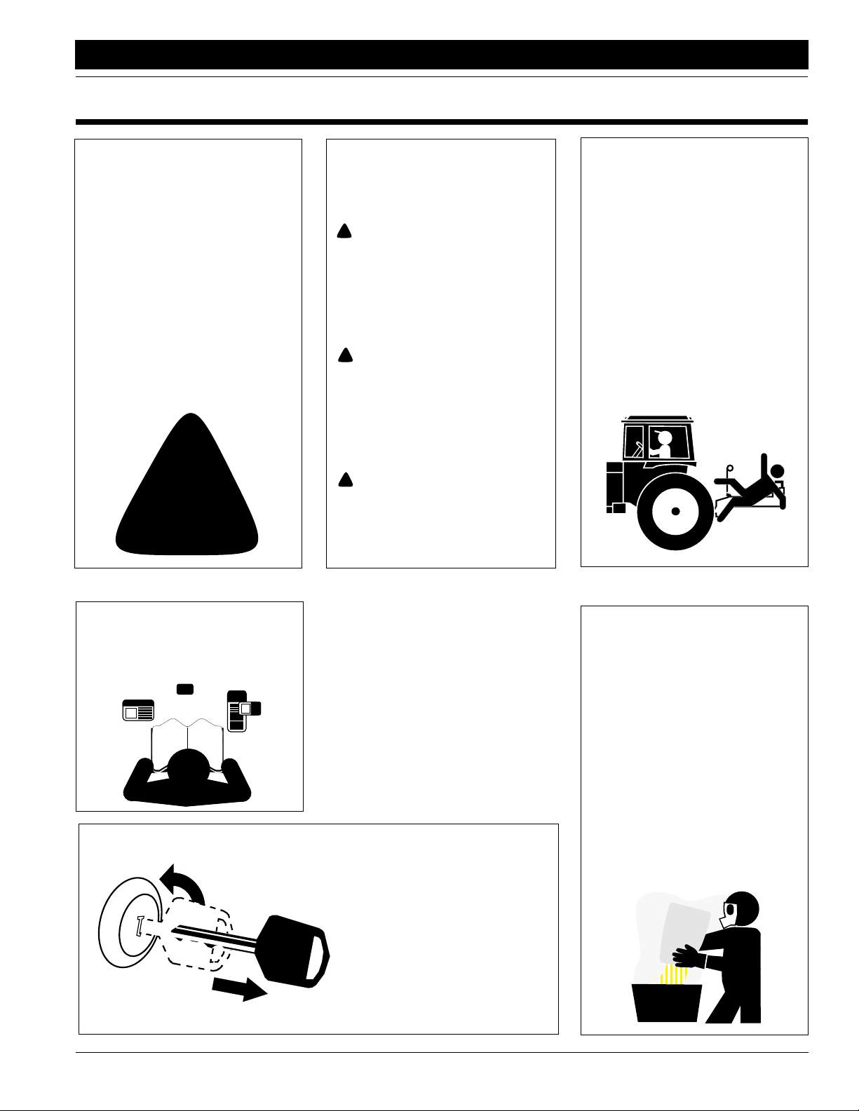
Keep Riders
Off Machinery
Riders obstruct the operator’s view.
Riders could be struck by foreign
objects or thrown from machine.
▲ Never allow riders on implement.
▲ Never allow children to operate
equipment.
For Your Protection
▲ Thoroughly read and understand
Safety Decals, page 5. Read all
instructions noted on decals.
OFF
Shutdown and Storage
▲ Lower machine to ground, put
tractor in park, turn off engine,
and remove key.
▲ Detach and store implement in an
area where children normally do
not play. Secure implement with
blocks and supports.
Handle
Chemicals Properly
Agricultural chemicals can be dangerous. Improper use can seriously
injure persons, animals, plants, soil
and property.
▲ Wear protective clothing.
▲ Handle all chemicals with care.
▲ Follow instructions on container
label.
▲ Avoid inhaling smoke from any
type of chemical fire.
▲ Store or dispose of unused chem-
icals as specified by chemical
manufacturer.
4/12/05
PT6030 and PT8030 Pull-Type Planter 401-032M-B
1
Page 4
Important Safety Information
Great Plains Mfg., Inc.
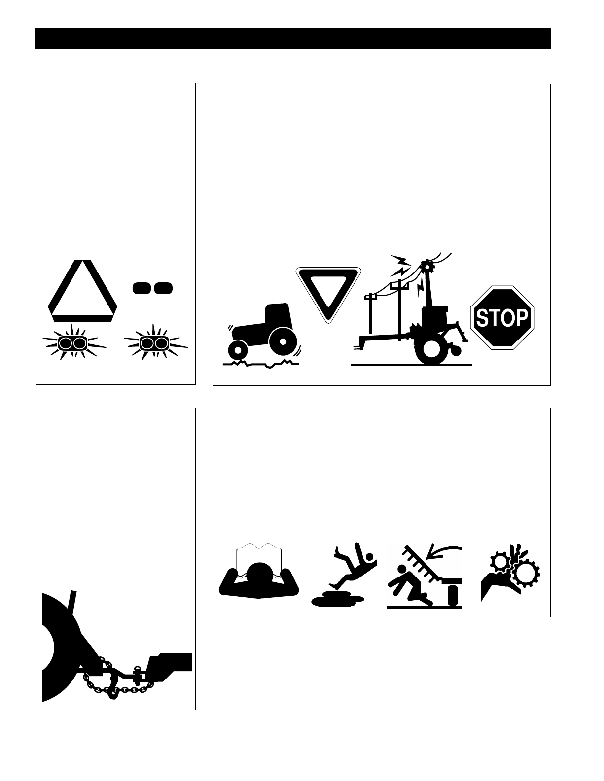
Use Safety
Lights and Devices
Slow-moving tractors, self-propelled
equipment and towed implements
can create a hazard when driven on
public roads. They are difficult to see,
especially at night.
▲ Use flashing warning lights and
turn signals whenever driving on
public roads.
▲ Use lights and devices provided
with implement.
Transport
Machinery Safely
Maximum transport speed for implement is 20 mph. Some rough terrains
require a slower speed. Sudden
braking can cause a towed load to
swerve and upset.
▲ Do not exceed 20 mph. Never
travel at a speed which does not
allow adequate control of steering
and stopping. Reduce speed if
towed load is not equipped with
brakes.
▲ Comply with state and local laws.
▲ Do not tow an implement that,
when fully loaded, weighs more
than 1.5 times the weight of towing vehicle.
Use A Safety Chain
▲ Use a safety chain to help con-
trol drawn machinery should it
separate from tractor drawbar.
▲ Use a chain with a strength rat-
ing equal to or greater than the
gross weight of towed machinery.
▲ Attach chain to tractor drawbar
support or other specified
anchor location. Allow only
enough slack in chain to permit
turning.
▲ Replace chain if any links or end
fittings are broken, stretched or
damaged.
▲ Do not use safety
chain for towing.
Practice Safe Maintenance
▲ Understand procedure before
doing work. Use proper tools and
equipment. Refer to this manual
for additional information.
▲ Work in a clean, dry area.
▲ Lower implement to ground, put
tractor in park, turn off engine,
and remove ke y before performing
maintenance.
▲ Allow implement to cool completely.
▲ Inspect all parts. Make sure parts
are in good condition and installed
properly.
▲ Remove buildup of grease, oil or
debris.
▲ Remove all tools and unused
parts from implement before operation.
PT6030 and PT8030 Pull-Type Planter 401-032M-B 4/12/05
2
Page 5
Great Plains Mfg., Inc.
Important Safety Information
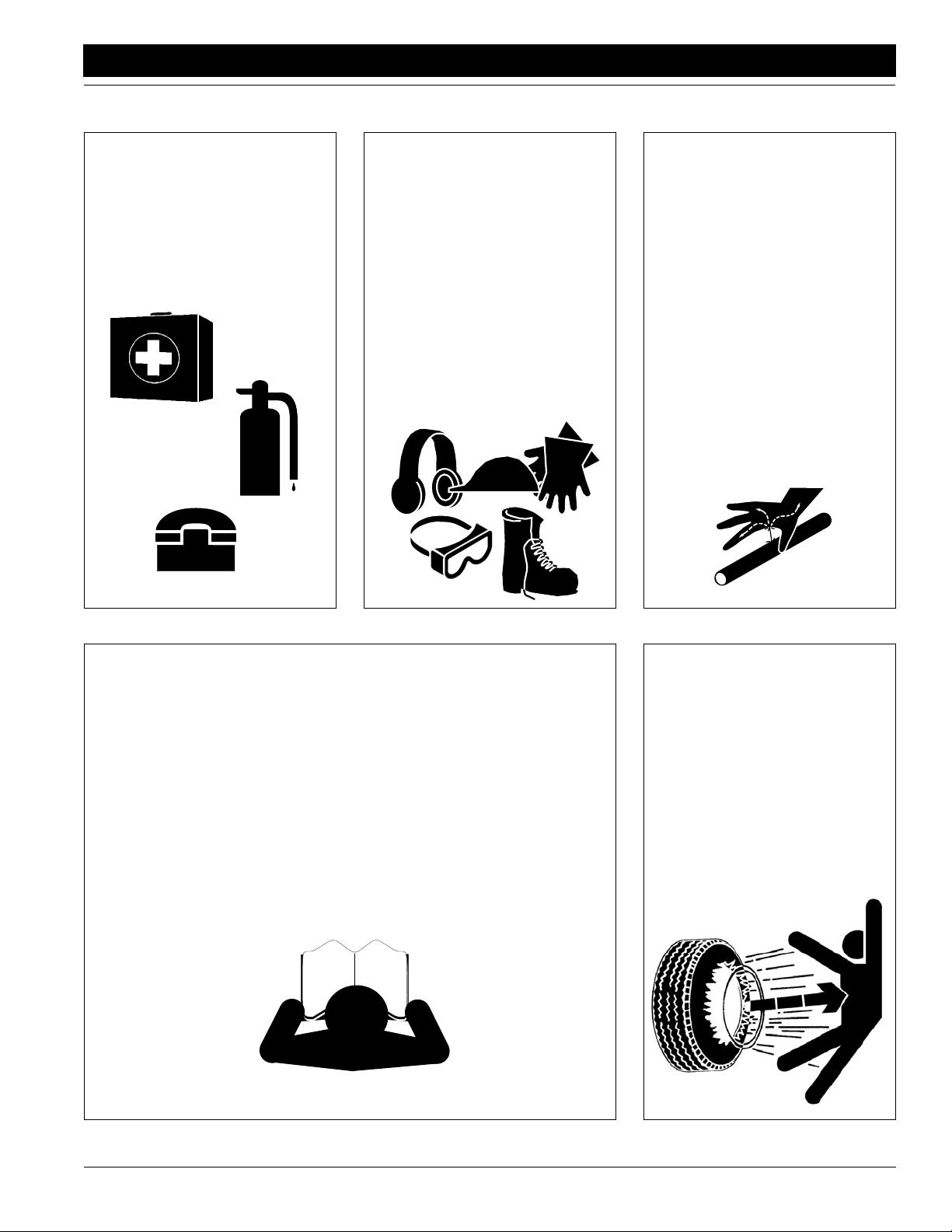
Prepare for Emergencies
▲ Be prepared if a fire starts.
▲ Keep a first aid kit and fire extin-
guisher handy.
▲ Keep emergency numbers for
doctor, ambulance, hospital and
fire department near phone.
911
Wear
Protective Equipment
▲ Wear protective clothing and
equipment.
▲ Wear clothing and equipment
appropriate for the job. Avoid
loose-fitting clothing.
▲ Because prolonged exposure to
loud noise can cause hearing
impairment or hearing loss, wear
suitable hearing protection such
as earmuffs or earplugs.
▲ Because operating equipment
safely requires your full attention,
avoid wearing radio headphones
while operating machinery.
Avoid High
Pressure Fluids Hazard
Escaping fluid under pressure can
penetrate skin, causing serious
injury.
▲ Avoid the hazard by relieving
pressure before disconnecting
hydraulic lines.
▲ Use a piece of paper or card-
board, NOT BODY PARTS, to
check for suspected leaks.
▲ Wear protective gloves and safety
glasses or goggles when working
with hydraulic systems.
▲ If an accident occurs, see a doc-
tor immediately. Any fluid injected
into the skin must be surgically
removed within a few hours or
gangrene may result.
Safety at All Times
Thoroughly read and understand this
manual before operating implement.
Refer to Safety Decals, page 5. Read
all instructions noted on decals.
▲ Be familiar with all implement
functions.
▲ Operate implement from driver’s
seat only.
▲ Do not leave tractor or implement
unattended with engine running.
▲ Do not dismount a moving tractor.
Dismounting a moving tractor could
cause serious injury or death.
▲ Do not stand between the tractor
and implement during hitching.
▲ Keep hands, feet and clothing
away from power-driven parts.
▲ Wear snug-fitting clothing to avoid
entanglement with moving parts.
▲ Watch out for wires, trees, etc.,
when raising implement. Make
sure all persons are clear of working area.
▲ Do not turn tractor too tight, caus-
ing implement to ride up on
wheels.
Tire Safety
Tire changing can be dangerous and
should be performed by trained personnel using correct tools and equipment.
▲ When inflating tires, use a clip-on
chuck and extension hose long
enough to allow you to stand to
one side–not in front of or over tire
assembly. Use a safety cage if
available.
▲ When removing and installing
wheels, use wheel-handling
equipment adequate for weight
involved.
4/12/05
PT6030 and PT8030 Pull-Type Planter 401-032M-B
3
Page 6
Important Safety Information
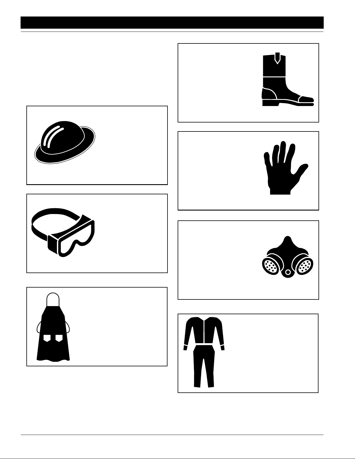
Personal Saf ety Equipment
Great Plains advises all users of chemical pesticides or herbicides to use the following personal safety equipment. Always follow the chemical label instructions, your safety and
the effectivity of the product depends upon your actions.
Waterproof, widebrimmed hat
Great Plains Mfg., Inc.
Waterproof boots or foot coverings
Waterproof, unlined gloves.
Neoprene gloves are recommended.
Face shield, goggles or full
face respirator. Goggles
with side shields or a full
face respirator is required if
handling or applying dusts,
wettable powders, or granules or if being exposed to
spray mist.
Waterproof apron
Cartridge-type respirator
approved for pesticide vapors unless label specifies
another type of respirator.
Cloth coveralls/outer clothing
changed daily; waterproof items
if there is a chance of becoming
wet with spray
PT6030 and PT8030 Pull-Type Planter 401-032M-B 4/12/05
4
Page 7
Great Plains Mfg., Inc.
Important Safety Information
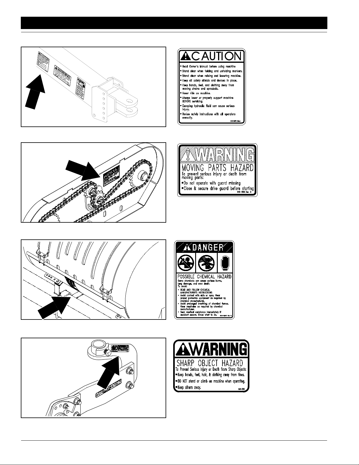
Safety Decals
Your implement comes equipped with all safety decals in place.
They were designed to help you safely operate your implement.
1. Read and follow decal directions.
2. Keep all safety decals clean and legible.
3. Replace all damaged or missing decals. Order new decals
from your Great Plains dealer. Refer to this section for
proper decal placement.
4. When ordering new parts or components, also request corresponding safety decals.
5. To install new decals:
a. Clean the area on which the decal is to be placed.
b. Peel backing from decal. Press firmly on surface,
being careful not to cause air bubbles under decal.
14945
12356
818-003C
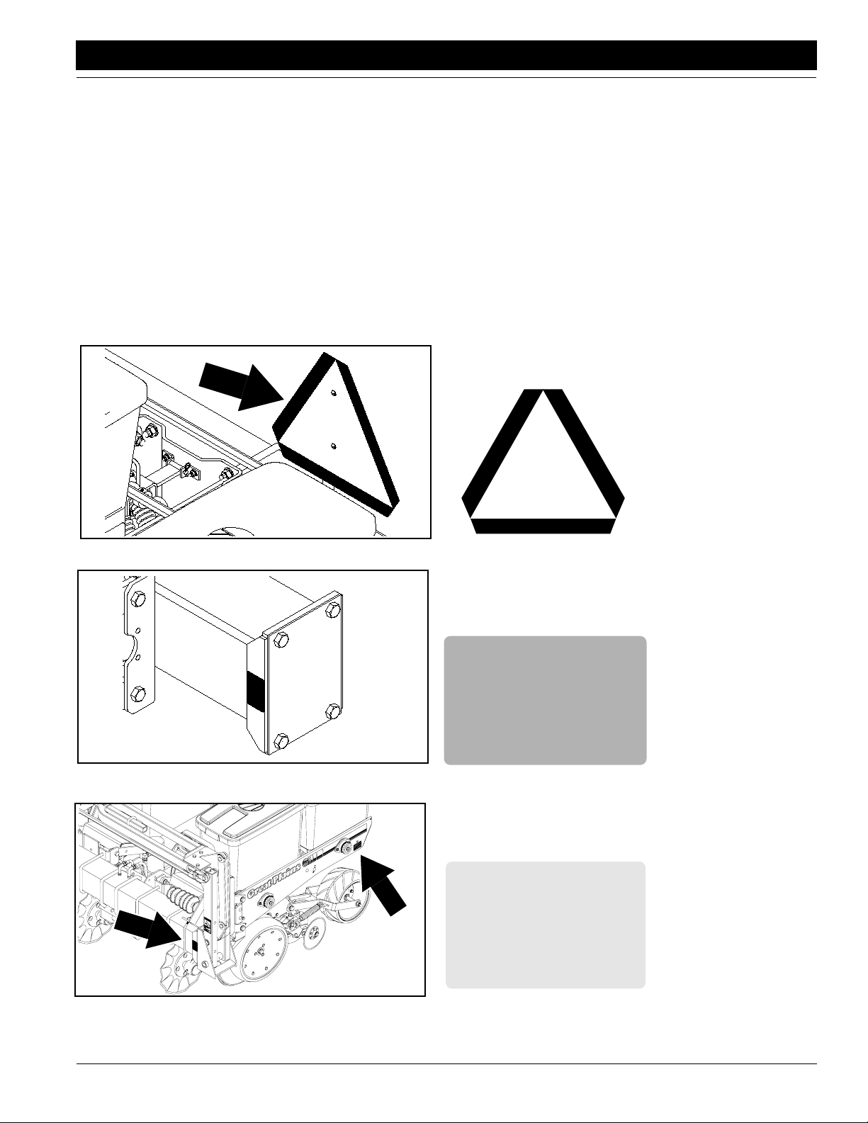
Slow Moving Vehicle Label
818-230C
Red Reflector
4/12/05
17936
818-229C
Amber Reflectors
PT6030 and PT8030 Pull-Type Planter 401-032M-B
5
Page 8
Important Safety Information
17920
Great Plains Mfg., Inc.
818-230C
Red Reflector
On outside row units;
two reflectors total
14919
17983
818-682C
Pinch/Crush Warning
818-188C
Transport Speed Warning
16861
PT6030 and PT8030 Pull-Type Planter 401-032M-B 4/12/05
6
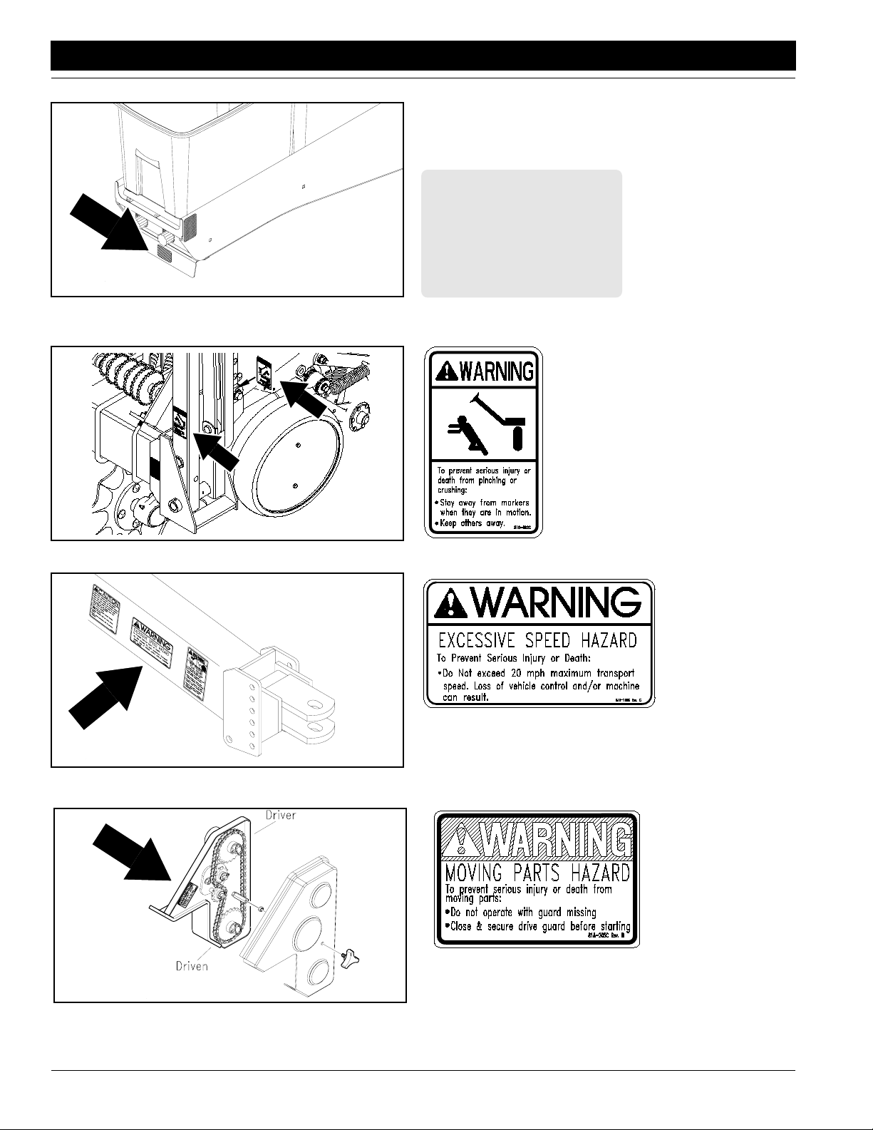
Moving Parts Warning
818-205C
Page 9
Great Plains Mfg., Inc.
Important Safety Information
16863
15720
818-205C
Moving Parts Warning
818-205C
Moving Parts Warning
15726
4/12/05
17983
818-323C
Ag Chemicals Caution
Located inside chemical
lids
818-339C
Warning High Pressure
PT6030 and PT8030 Pull-Type Planter 401-032M-B
7
Page 10
Important Safety Information
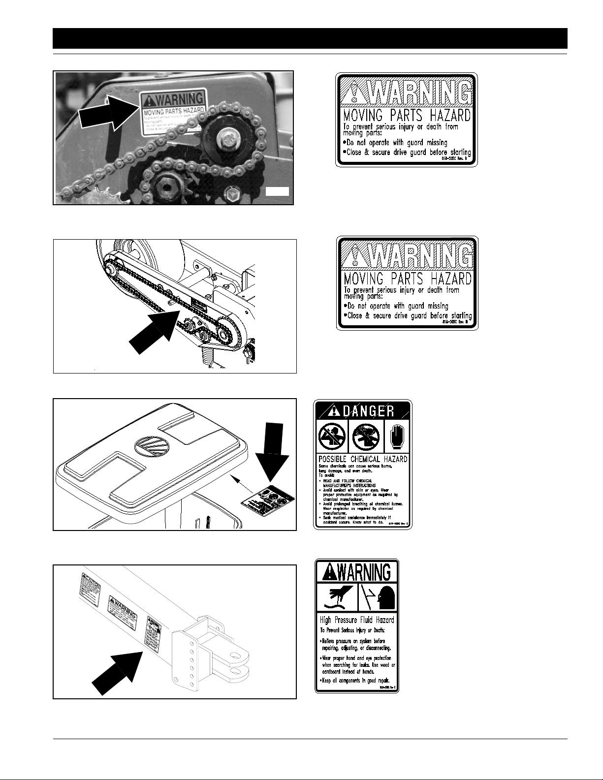
17983
Great Plains Mfg., Inc.
818-587C
Operational Caution
16864
15723
818-205C
Moving Parts Warning
Liquid-Dry Fertilizer Option
818-323C
Chemical Hazard Warning
Liquid Fertilizer Option
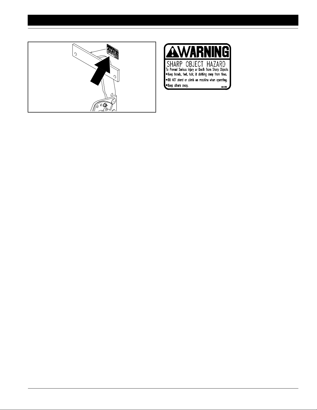
818-525C
15732
PT6030 and PT8030 Pull-Type Planter 401-032M-B 4/12/05
8
Sharp Object Warning
Optional Terra-Tine
Page 11
Great Plains Mfg., Inc.
Important Safety Information
15733
818-525C
Sharp Object Warning
Optional Terra-Tine
4/12/05
PT6030 and PT8030 Pull-Type Planter 401-032M-B
9
Page 12
Introduction
Introduction
Great Plains Mfg., Inc.
Great Plains welcomes you to its growing family of new
product owners. This implement has been designed with
care and built by skilled workers using quality materials.
Proper setup, maintenance and safe oper ating pr actices
will help you get years of satisf actory use from the ma
-
chine.
Description of Unit
The 6- and 8-row , pull-type planter is a to wed planting implement. The frame consists of 7-by-7-inch tubing. Planting rates are adjustable by changing sproc k ets on the
planter transmission or contact drive. Row units are
mounted on the frame. Seed hoppers are standard on the
row units; chemical hoppers and granular-chemical appli
cators are available . Springs on each row unit provide
down pressure needed for the double-disk openers to
make a seed trench. Finger-pickup meters singulate and
dispense seed from the hopper and deliver it to the trench.
Seeding depth is controlled by side gauge wheels on the
openers. Closing wheels or disks close the trench. With an
optional 5-by-7-inch fertilizer bar , the planter can be outfit
ted with dry or liquid fertilizer application and tillage attachments.
Intended Usage
Use this implement for planting row crops in large fields.
T ow the implement behind an agricultural tractor at speeds
of less than 20 mph. The unit is designed for conv ention
ally tilled fields but can be used in no- or minimum-till conditions if outfitted with optional tillage attachments.
Using This Manual
This manual will familiarize you with safety, assembly, operation, adjustments, troubleshooting and maintenance.
Read this manual and follow the recommendations to help
ensure safe and efficient operation.
The information in this manual is current at printing. Some
parts may change to assure top performance.
Definitions
Right-hand and left-hand as used in this manual are determined by facing the direction the machine will tra v el while
in use unless otherwise stated.
IMPORTANT: A crucial point of information related to
the preceding topic. For safe and correct oper ation,
read and follow the directions provided before continuing.
NOTE: Useful inf ormation related to the preceding topic.
Owner Assistance
If you need customer service or repair parts, contact a
Great Plains dealer. The y ha ve trained personnel, repair
parts and equipment specially designed for Great Plains
products.
Your machine’s parts were specially designed and should
only be replaced with Great Plains parts. Always use the
serial and model number when ordering parts from your
Great Plains dealer. The serial-number plate is located on
the 7-by-7-inch, main frame tube on the left-hand side of
the planter as shown in Figure A.
-
-
Great Plains
MANUFACTURING INCORPORATED
ASSARIA, KANSAS 67416
MODEL NO.
PT 6030
SERIAL NO.
-
14921
Record your planter model and serial number here for quick
reference:
Model Number: _________________________________
Serial Number: _________________________________
Your Great Plains dealer wants you to be satisfied with
your new machine. If y ou do not understand an y part of
this manual or are not satisfied with the service received,
please take the following actions .
1. Discuss the matter with y our dealership service manager. Mak e sure the y are aw are of an y prob lems so
they can assist you.
2. If you are still not satisfied, seek out the owner or general manager of the dealership.
3. For further assistance write to:
Product Support
Great Plains Mfg. Inc., Service Department
Salina, KS 67402-5060
GP-U0000000
Figure A
Serial Number
PO Box 5060
PT6030 and PT8030 Pull-Type Planter 401-032M-B 4/12/05
10
Page 13
Great Plains Mfg., Inc.
Section 1 Planter Preparation and Setup
Section 1 Planter Preparation and Setup
This section will help you prepare your tractor and planter
for use. The planter must be hitched on a suitab le tr actor
and leveled.
Prestart Checklist
1. Read and understand “Important Safety Information,” beginning on page 1.
2. Check that all working parts are moving freely, bolts
are tight, and cotter pins are spread.
3. Check that all grease fittings are in place and lubricated. Refer to Lubrication, “Maintenance and Lubri-
cation,” page 44.
4. Check the chains for proper tension and alignment.
Lubricate chains thoroughly.
5. Check that all safety decals and reflectors are legib le.
Replace if damaged. Refer to Safety Decals , “Impor
tant Safety Information,” page 5.
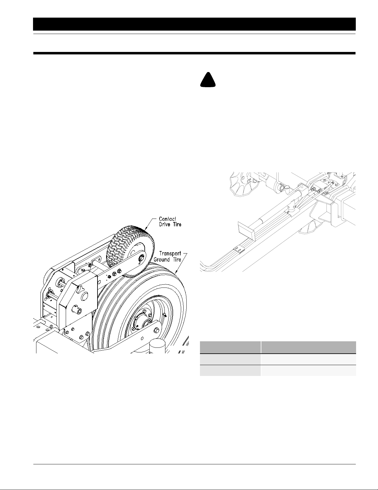
6. Inflate tires as recommended. Refer to Figure 1-1.
Transport/Ground Drive 9.5L X 15-8 ply . . . . . 44 psi
Contact Drive 13-5.0 X 6. . . . . . . . . . . . . . . . . 40 psi
Hitching Planter to Tractor
!
DANGER!
Y ou may be se ver ely injur ed or killed by being crushed between
the tractor and planter. Do not stand or place any part of your
body between planter and moving tractor. Stop tractor engine
and set park brake before installing hitch pin.
1. T o prev ent soil compaction on rows, set tractor wheels
at 60 inches center to center. For hillsides and steep
slopes, set tractor wheels as wide as possible f or max
imum stability.
2. Use jack to raise and lower planter tongue . After hitching tractor to planter, store jac k on storage tube on top
-
of planter tongue as shown in
Figure 1-2.
-
Figure 1-1
Contact Drive Transport/Ground Drive
15057
17930
Figure 1-2
Jack in Storage Position
3. Secure planter safety chain to an anchor on the tractor
capable of pulling the unit.
Hydraulic Hose Hookup
Great Plains hydraulic hoses are color coded to help you
hookup hoses to your tractor outlets. Hoses that go to the
same remote valve are marked with the same color.
Color Hydraulic Function
Orange Marker Cylinders
Blue Lift Cylinders
4/12/05
PT6030 and PT8030 Pull-Type Planter 401-032M-B
11
Page 14
Section 1 Planter Preparation and Setup
Great Plains Mfg., Inc.
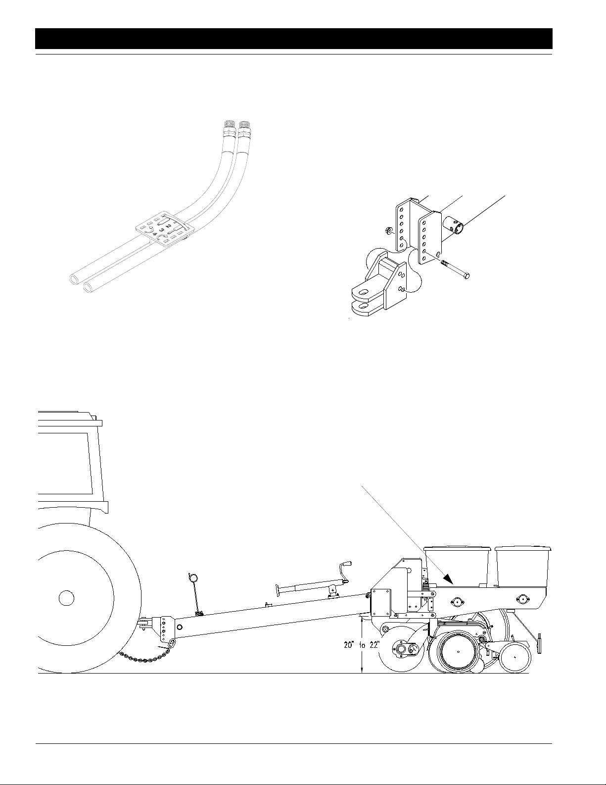
T o distinguish hoses on the same h ydraulic circuit, refer to
plastic hose holder. See
Figure 1-3. Hose under extended-cylinder symbol feeds cylinder base ends and raises
the planter. Hose under retracted-cylinder symbol feeds
cylinder rod ends and lowers planter .
17641
Figure 1-3
Hydraulic Hose Label
Leveling Planter
During initial setup and periodically throughout the season, check that the planter runs level. When planting, the
top of the hopper support panel should be parallel to the
ground as shown in
T o lev el the planter, the bottom of the mainframe tube must
run between 20 and 22 inches above ground when low
ered into planting position. See Figure 1-5.
T o obtain the correct height, reposition the planter hitch on
the tongue. The hitch can be turned over for different
heights. See Figure 1-4.
Figure 1-5.
-
Figure 1-4
Hitch Height Adjustment
Top of Hopper Support Level with Ground
Figure 1-5
Leveling the Planter
PT6030 and PT8030 Pull-Type Planter 401-032M-B 4/12/05
12
14956
Page 15
Great Plains Mfg., Inc.
Section 1 Planter Preparation and Setup
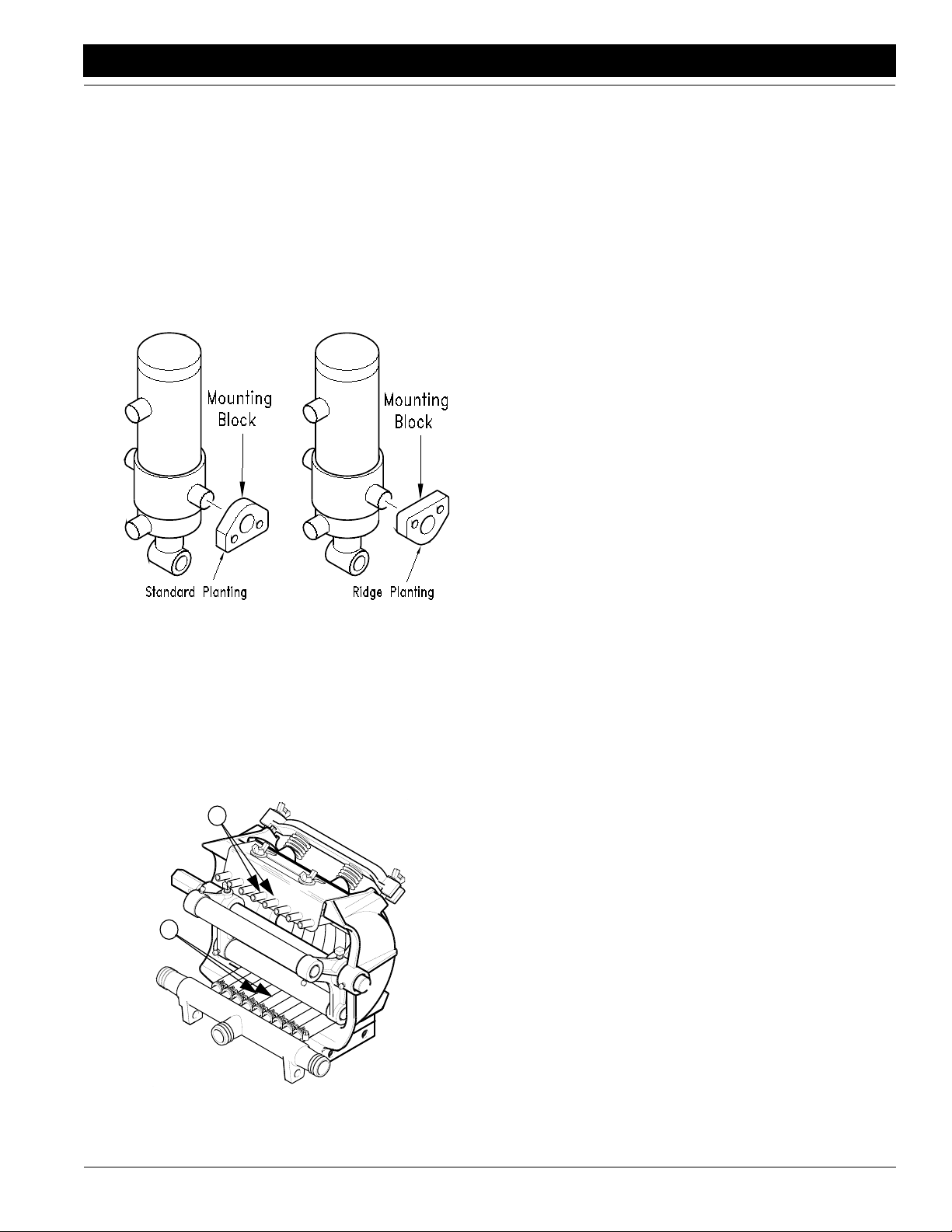
Ridge Planting
To prepare the planter for ridge planting, you must lower
the gauge wheels by inverting the cylinder mounting
blocks.
To invert, refer to Figure 1-6.
1. Block up the frame to remov e weight from tires.
2. Remove the f our 5/8-inch cap scre ws .
3. Invert mounting blocks and reinstall cap screws .
Torque to specification as listed on the Torque Values
Chart,
“Appendix” on page 55.
Figure 1-6
Ridge Planting Adjustment
14958
Liquid Fertilizer Option
The pump should always be mounted e ven with or lower
than the fertilizer tank.
Hose arrangement is important for efficient pump operation. If you will be using fe wer hoses than there are on the
pump, remov e pump hoses from near the center of the in
take manifold (1) and cap the intak e ports (2).
2
1
-
4/12/05
Figure 1-7
Removing Squeeze Pump Hoses
12409
PT6030 and PT8030 Pull-Type Planter 401-032M-B
13
Page 16
Section 2 Operating Instructions
Section 2 Operating Instructions
Great Plains Mfg., Inc.
This section covers general operating procedures . Experience, machine familiarity and the follo wing information will
lead to efficient operation and good working habits. Al
ways operate farm machinery with safety in mind.
-
Prestart Checklist
1. Carefully read “Important Safety Information,” beginning on page 1.
2. Clean any dirt or grease off chains and other moving
parts. Check chains for proper tension and alignment
as shown in Chain T ension, “Maintenance and Lubri
cation,” page 39.
3. Check that planter tires are the correct size and properly inflated as indicated on Tire Inflation Chart, “Ap-
pendix,” page 56.
4. Check all bolts, pins and fasteners. T orque as specified on Torque Values Chart, “Appendix,” page 55.
5. Lubricate planter as indicated under Lubrication,
“Maintenance and Lubrication,”
6. Check planter for worn or damaged parts. Repair or
replace before going to the field.
7. Check that hoppers are free of dirt and debris. Turn
meter-drive shaft by hand to be sure drive shaft and
seed meter turn freely .
page 44.
Field Operation
1. Perf orm all checks listed on Prestart Checklist, this
page.
2. Hitch planter to a tractor with sufficient horsepower.
Refer to Tractor Requirements, “Specifications and
Capacities,”
“Preparation and Setup,” page 11.
3. Set and calibrate planting rate as explained under
Planting Rate, “Adjustments,”
4. Load seed hoppers with clean seed. Add 1 teaspoon
of graphite to each seed hopper . Replace hopper lids.
5. Adjust down pressure on row units to match field conditions. Set row units to desired planting depth. Refer
to Row Unit Adjustments, “Adjustments,”
6. Check if planter is lev el. Refer to Leveling Planter ,
“Preparation and Setup,”
7. Lower planter , pull forward and begin planting.
8. Always raise planter for field turns. Meters will stop
automatically as you raise planters.
page 53, and Hitching Planter to T ractor ,
page 17.
page 28.
page 12.
Meter Clutches
To disengage seed- and chemical-hopper clutches, pull
and rotate knobs until meters are disengaged. See
2-1.
-
17887
Figure 2-1
Meter Clutch
To engage clutches, pull and rotate knobs until meters
reengage.
Row Unit Operation
Never back up with row units in ground. If you do , check all
openers to be sure none are clogged. Always lift planter
out of ground when turning at row ends and for other
short-radius turns.
For information on planting-depth and down-pressure
adjustments, refer to Row Unit Adjustments , “Adjust
ments,” beginning on page 28.
Chemical Hoppers
The optional chemical hopper comes in two versions: one
chemical meter or two chemical meters with a divider that
separates the hopper into two compartments.
Before filling chemical hoppers, clean any f oreign objects
out of hoppers. To remove hopper from row unit, disen
gage meter clutch and undo over-center latch at front of
hopper. See
Set and calibrate chemical-application rate as explained
under Granular Chemical Rates, “Adjustments,”
Fill chemical hoppers and replace hopper lids before operating planter.
Periodically clean dirt and foreign objects out of chemical
hoppers.
Figure 2-2.
Figure
-
-
page 21.
PT6030 and PT8030 Pull-Type Planter 401-032M-B 4/12/05
14
Page 17
Great Plains Mfg., Inc.
Section 2 Operating Instructions
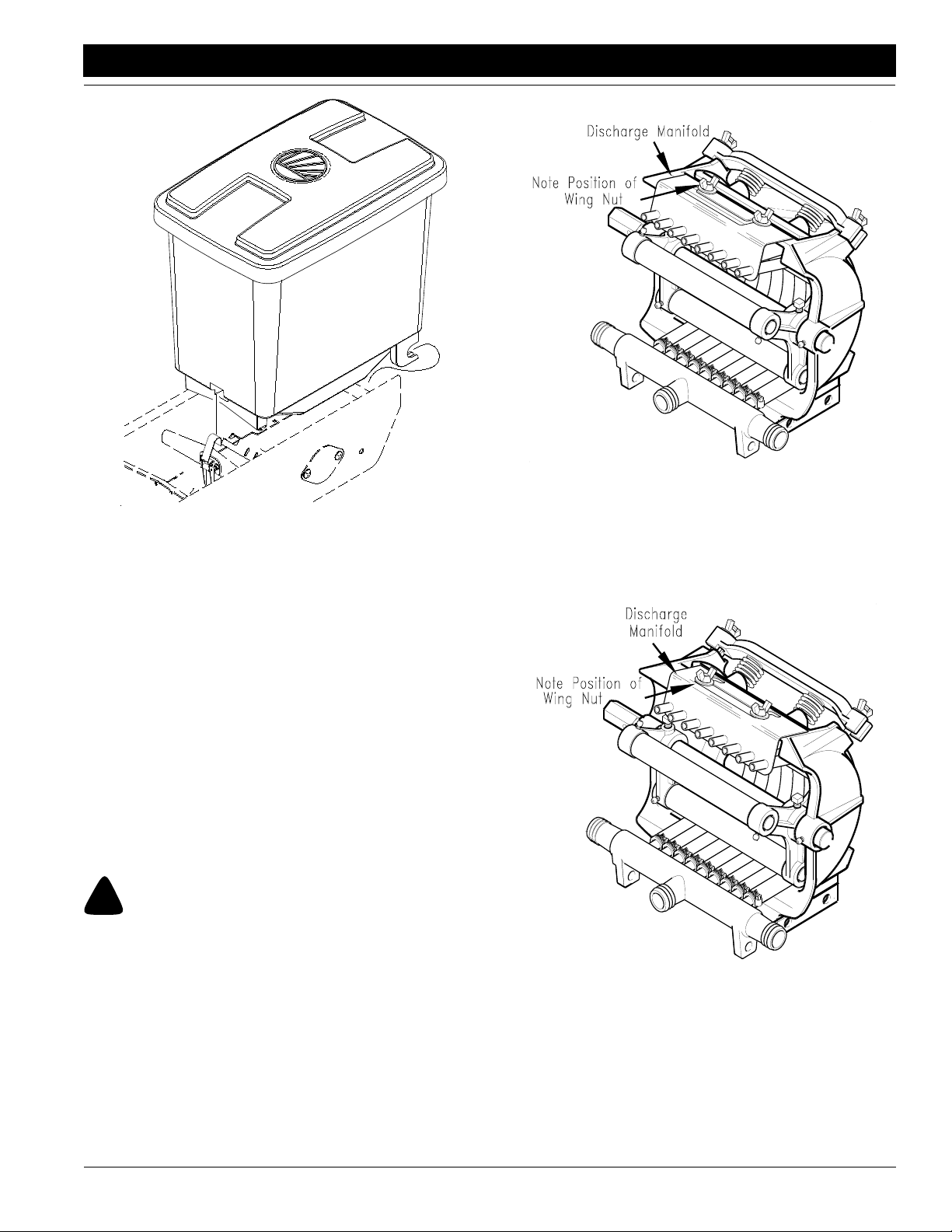
Secure wing nuts as shown in Figure 2-3.
14949
16866
Figure 2-2
Chemical Hopper
Marker Operation
Markers can be raised simultaneously but must be lo wered one at a time. If both markers are required down at
the same time, run one marker down, momentarily start to
raise it, reverse the h ydraulic le v er and lower the opposite
marker. Holding the lever down will force both markers
down.
On a tractor where the oil flow cannot be controlled, the
rate of flow of oil from the tractor may be g reater than the
rate at which the marker cylinder can accept it. The tractor
hydraulic control le ver will have to be held until the cylinder
reaches the end of its stroke. This occurs most often on
tractors with an open-center hydraulic system.
On tractors with a closed-center hydraulic system, the
tractor’s hydraulic flow control can be set so the tractor’s
detent will function properly.
Liquid Fertilizer Operation
!
WARNING!
Agricultural chemicals can be dangerous if not selected and
handled with care. Always read and follow directions supplied
by the chemical manufacturer.
For accurate metering, keep pump speed below 125 rpm.
To operate the pump, the discharge manif old must be in
the forward position as shown in
shipped in the rearward position.
To position the manifold forw ard for operation, loosen the
wing nuts on the manifold and pull the manif old forward.
Figure 2-3. Pumps are
Figure 2-3
Discharge Manifold Forward Position–In Use
When the pump is not in use, reposition the pump manifold
to prolong the life of the hoses in the squeeze pump . To re
position the discharge manifold to the rearward position,
loosen the wing nuts and push the manifold back as
shown in
For more information on preparing the squeeze pump for
parking and storage, refer to Squeeze Pumps , “Mainte
nance and Lubrication,” page 43 and the John Blue
manual provided with the pumps.
Figure 2-4.
14950
Figure 2-4
Discharge Manifold Rearward Position–Parking
-
-
4/12/05
PT6030 and PT8030 Pull-Type Planter 401-032M-B
15
Page 18
Section 2 Operating Instructions
Great Plains Mfg., Inc.
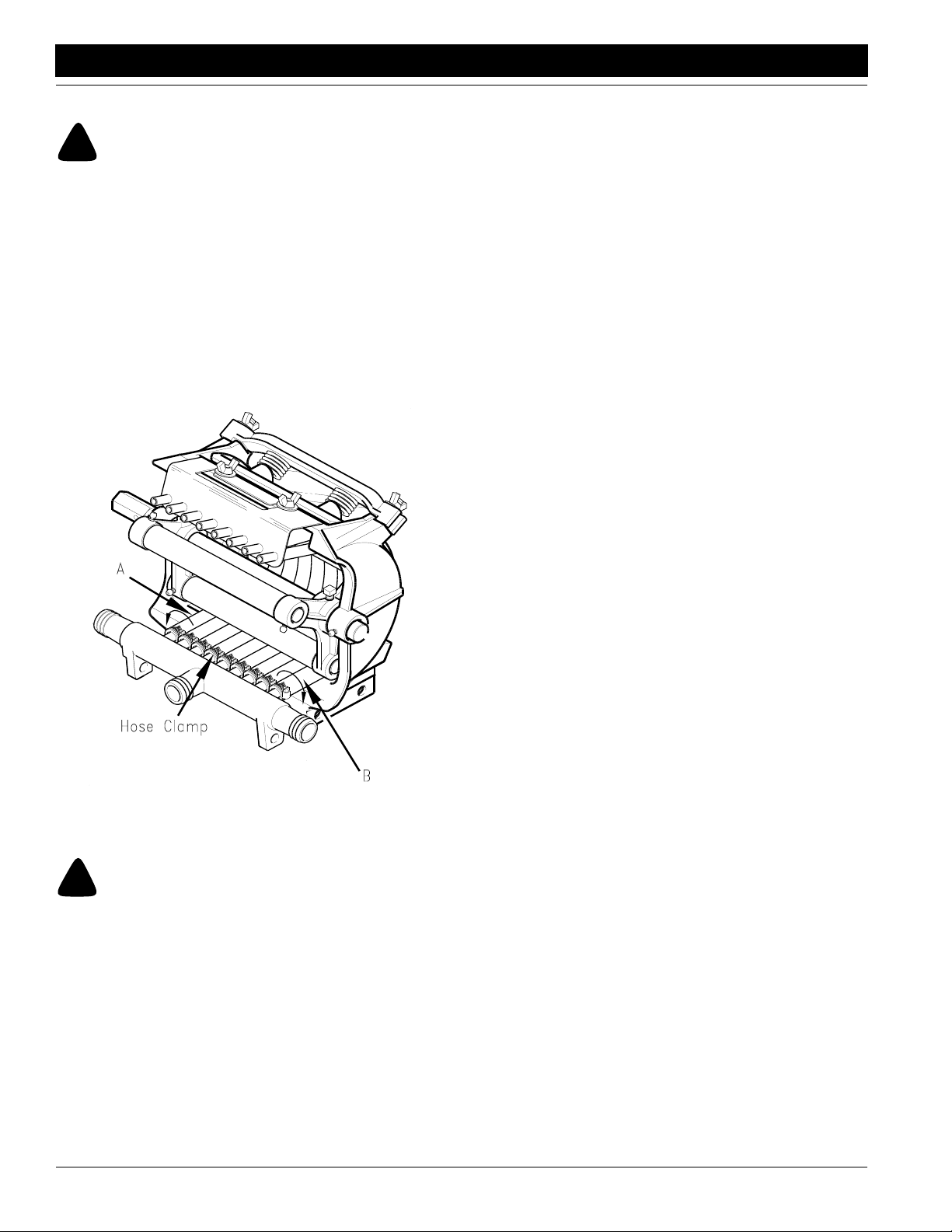
Squeeze Pump Hose Alignment
!
CAUTION!
Avoid pr essure when using the quic k-fill attachment. The rubber
plugs installed in the manifold may be forced out under pres
sure.
Refer to Figure 2-5.
If end hoses (A and B) should run off the back, realign hos-
es as follows:
1. On hose A, loosen hose clamps on intake manifold
and twist hose counterclockwise 1/4 turn.
2. On hose B, loosen hose clamp on intake manif old and
twist hose clockwise 1/4 turn.
3. Retighten hose clamp.
-
Tractor Requirements, “Specifications and Capaci-
ties,” page 53, and Hitching Planter to Tractor, “Prep-
aration and Setup,” page 11.
2. Unload hoppers before transporting if at all possible.
The planter can be transported with full hoppers, but
the added weight will increase stopping distance and
decrease maneuverability.
3. Check that tires are properly inflated. Refer to Tire
Inflation Chart, “Appendix,”
4. Comply with all federal, state and local laws when
traveling on pub lic roads .
5. Remember that the planter is wider than the tractor.
Allow safe clearance .
6. Transport slowly over uneven or rough terrain.
page 56.
Parking
See also Storage, “Maintenance and Lubrication,”
page 43, for information on long-term storage.
1. Park planter on a lev el, solid area.
2. Place jack on stob on the side of the planter tongue.
Lower jack until weight of planter is off of tractor dr aw
bar. Remove hitch pin and safety chain.
3. Disconnect any hydraulic hoses from tractor. Do not
let hose ends rest on the ground.
-
12402
Figure 2-5
Hose Alignment
Transporting
!
WARNING!
Towing the planter at high speeds can lead to loss of vehicle
control. Loss of vehicle control can lead to serious road acci
dents, injury and death. Do not exceed 20 mph.
Before transporting the planter, chec k and practice the following items.
1. Check that planter is securely hitched to a sufficient
tractor. Alw ays use a locking-style hitch pin sized to
match holes in hitch and drawbar (minimum 1-inch-di
ameter, heat-treated pin). Attach saf ety chain to tr actor with enough slack to permit turning. Refer to
PT6030 and PT8030 Pull-Type Planter 401-032M-B 4/12/05
16
-
-
Page 19
Great Plains Mfg., Inc.
Section 3 Adjustments
Section 3 Adjustments
Planting Rate
T ransmission Adjustment
To change the planting population, change the sprocket
combination on the transmission.
1. Refer to Planting Rates for Finger Pickup Corn
Meters,
page 19, for proper sprock et combination for your desired planting population.
2. Remove cov er from tr ansmission by loosening knob
on cover. See
3. Loosen carriage bolt and flange nut on idler plate. Rotate idler plate and move idlers out of chain.
4. Remove chain. Place correct sprock ets for desired
planting rate on shafts. Store all unused sprock ets on
storage bracket.
5. Reroute chain over idlers and sprock ets .
6. T urn idler plate counterclockwise to take up all b ut 1/4inch slack out of chain. Retighten carriage bolt and
flange nut on idler plate.
7. Replace transmission cover and hand tighten knob.
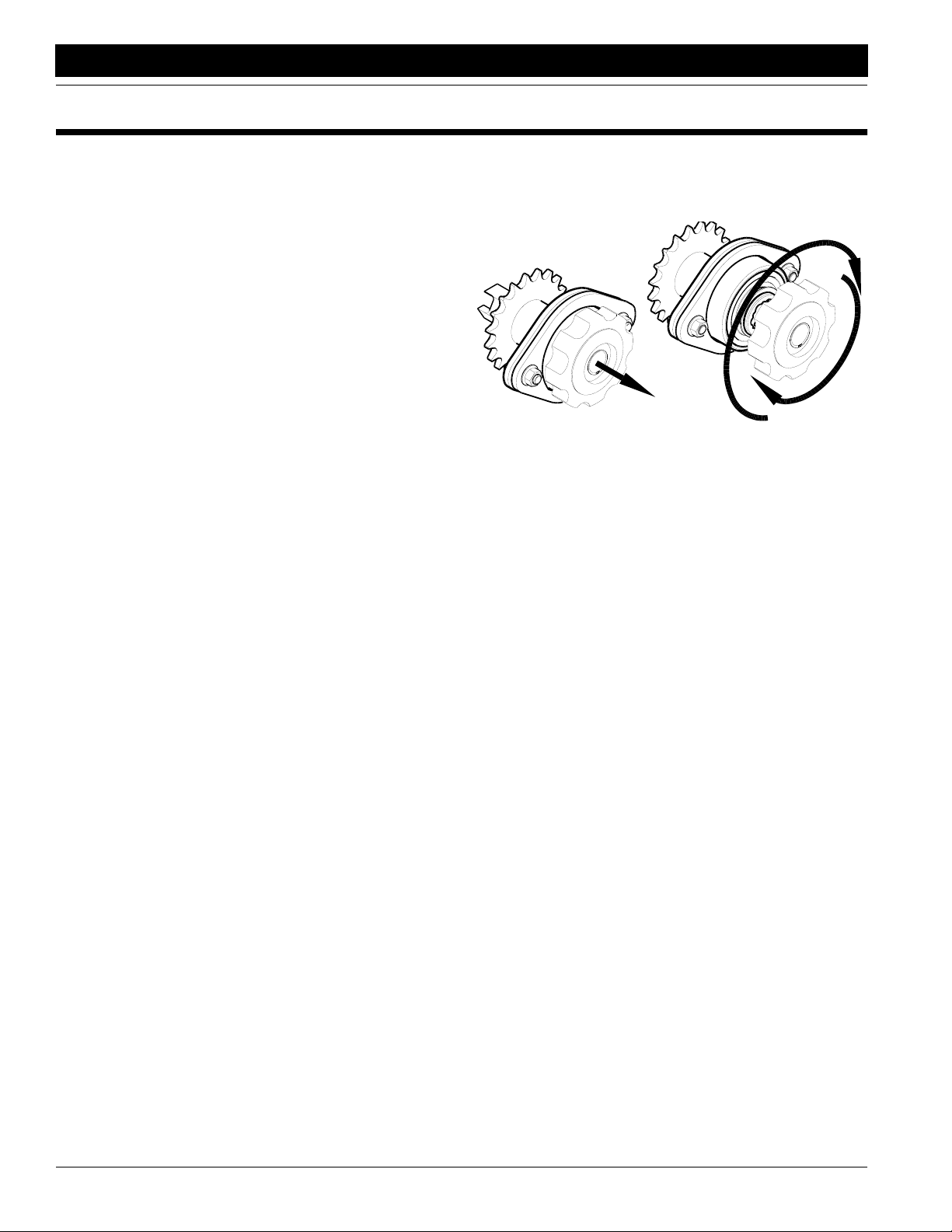
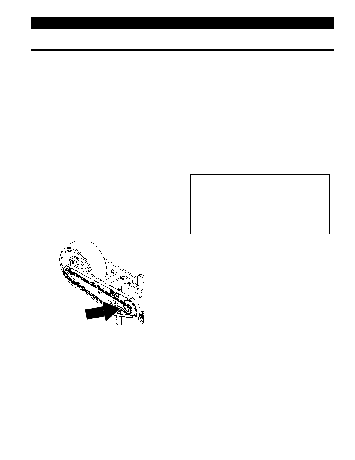
2-to-1 Drive Reduction
The charts on page 18 and page 19 are based on a 15tooth, driven sprocket in the contact-wheel drive . To reduce planting rates by one-half, s witch to 28-tooth sproc ket. See Figure 3-1.
page 18, or Planting Rates for Brush Meters,
Figure 3-2.
Checking Planting Population
After setting transmission, always field chec k planting
population as follows.
1. Release spring pressure on closing wheels or disks.
2. Tie up closing disks or wheels to hopper support using
a chain or heavy wire. Lock up optional Seed-Lok
wheels.
3. Adjust planting depth to a shallow setting.
4. Plant at a normal speed for a short distance.
5. For 30-inch rows, measure 17 f eet 6 inches (one-thousandth of an acre).
6. Count the number of seeds in one row over the measured distance.
7. Multiply the number of seeds counted by 1000. This
gives you total population.
Example
• 30-inch row spacing
• Measure 17 feet 6 inches
• 24 seeds over measured distance in one row
24 X1000 = 24,000 plant population per acre
If the planting population is significantly different than desired, make the following checks.
• Double check the sprocket combination in the transmission. Refer to Planting Rates for Corn Meters,
page 18, or Planting Rates for Brush Meters, page 19.
• Check air pressure in the gauge-wheel tires. Refer to
Tire Inflation Chart, “Appendix,”
• Check for meter malfunction or excessive contactdrive-wheel slippage. Refer to “Troubleshooting,”
page 34.
page 56.
4/12/05
Figure 3-1
2-to-1 Drive Reduction
16863
PT6030 and PT8030 Pull-Type Planter 401-032M-B
17
Page 20

Section 3 Adjustments
Planting Rates for Finger Pickup Corn Meters
Great Plains Mfg., Inc.
Drive
Driven
Figure 3-2
Planter Transmission Drive and Driven Sprockets
Planting Rates 30-Inch Row Width
Planting
Population/
Acre
16,074 17 28 4 to 8 13.0
16,668 17 27 4 to 8 12.5
17,313 17 26 4 to 8 12.1
17,971 19 28 4 to 8 11.6
13,228 17 25 4 to 8 15.8
16,674 19 27 4 to 8 12.5
18,739 17 24 4 to 8 11.2
19,323 19 26 4 to 8 10.8
19,550 17 23 4 to 8 10.7
20,093 19 25 4 to 8 10.4
20,922 19 24 4 to 8 10.0
21,692 23 28 4 to 8 9.6
21,828 19 23 4 to 8 9.6
22,493 23 27 4 to 8 9.3
22,632 24 28 4 to 8 9.2
23,355 23 26 4 to 8 9.0
23,467 24 27 4 to 8 8.9
23,565 25 28 4 to 8 8.9
Transmission
Sprockets
Drive Driven
Recom-
mended Speed
Range (mph)
Average Seed
Spacing
(inches)
16861
Planting Rates 30-Inch Row Width
Planting
Population/
Acre
23,630 17 19 4 to 7.5 8.8
24,286 23 25 4 to 7.5 8.6
24,367 24 26 4 to 7.5 8.6
24,435 25 27 4 to 7.5 8.6
24,504 26 28 4 to 7.5 8.5
25,288 23 24 4 to 7.5 8.3
25,338 24 25 4 to 7.5 8.3
25,372 25 26 4 to 7.5 8.2
25,409 26 27 4 to 7.5 8.2
25,444 27 28 4 to 7.5 8.2
26,383 23 23 4 to 7 7.9
27,357 28 27 4 to 7 7.6
27,394 27 26 4 to 7 7.6
27,471 25 24 4 to 7 7.6
27,525 24 23 4 to 7 7.6
28,406 28 26 4 to 6.5 7.4
28,486 27 25 4 to 6.5 7.3
28,661 25 23 4 to 6.5 7.3
29,457 19 17 4 to 6.5 7.1
29,538 28 25 4 to 6.5 7.1
29,661 27 24 4 to 6.5 7.0
29,803 26 23 4 to 6.5 7.0
30,756 28 24 3 to 6 6.8
30,945 27 23 3 to 6 6.8
31,889 23 19 3 to 5.5 6.6
32,088 28 23 3 to 5.5 6.5
33,270 24 19 3 to 5.5 6.3
34,642 25 19 3 to 5 6.0
35,604 23 17 3 to 5 5.9
36,023 26 19 3 to 5 5.8
37,146 24 17 3 to 5 5.6
37,403 27 19 3 to 5 5.6
38,678 25 17 3 to 4.5 5.4
38,784 28 19 3 to 4.5 5.4
40,219 26 17 3 to 4.5 5.2
41,761 27 17 3 to 4.5 5.0
43,303 28 17 3 to 4.5 4.8
Transmission
Sprockets
Drive Driven
Recom-
mended Speed
Range (mph)
Average Seed
Spacing
(inches)
PT6030 and PT8030 Pull-Type Planter 401-032M-B 4/12/05
18
Page 21

Great Plains Mfg., Inc.
Section 3 Adjustments
Planting Rates for Brush Meters
Planting Rates 30-Inch Row Width
60 Cell
Soybean or
High Rate Milo/
Speed
Sprockets
Transmission
Drive Driven
17 28 2 to 8 80,928 2.6 64,742 3.2 48,557 4.3 40,464 5.2
17 27 2 to 8 83,926 2.5 67,141 3.1 50,356 4.2 41,963 5.0
17 26 2 to 8 87,154 2.4 69,723 3.0 52,292 4.0 43,577 4.8
19 28 2 to 8 90,449 2.3 72,359 2.9 54,269 3.9 45,225 4.6
19 27 2 to 8 93,799 2.2 75,039 2.8 56,279 3.7 46,900 4.5
17 24 2 to 8 94,416 2.2 75,533 2.8 56,650 3.7 47,208 4.4
17 23 2 to 8 98,521 2.1 78,817 2.7 59,113 3.5 49,261 4.2
19 25 2 to 8 101,303 2.1 81,042 2.6 60,782 3.4 50,652 4.1
19 24 2 to 8 105,524 2.0 84,419 2.5 63,314 3.3 52,762 4.0
23 28 2 to 8 109,491 1.9 87,593 2.4 65,695 3.2 54,746 3.8
19 23 2 to 8 110,112 1.9 88,090 2.4 66,067 3.2 55,056 3.8
24 28 2 to 8 114,252 1.8 91,402 2.3 68,551 3.0 57,126 3.7
24 27 2 to 8 118,483 1.8 94,786 2.2 71,090 2.9 59,242 3.5
17 19 2 to 8 119,263 1.8 95,410 2.2 71,558 2.9 59,631 3.5
24 26 2 to 8 123,040 1.7 98,432 2.1 73,824 2.8 61,520 3.4
26 28 2 to 8 123,773 1.7 99,018 2.1 74,264 2.8 61,886 3.4
24 25 2 to 8 127,962 1.6 102,370 2.0 76,772 2.7 63,981 3.3
26 27 2 to 8 128,357 1.6 102,686 2.0 77,014 2.7 64,178 3.3
23 23 2 to 8 133,294 1.6 106,635 2.0 79,976 2.6 66,647 3.1
27 26 2 to 8 138,420 1.5 110,736 1.9 83,052 2.5 69,210 3.0
24 23 2 to 8 139,089 1.5 111,271 1.9 83,453 2.5 69,544 3.0
25 23 2 to 8 144,884 1.4 115,907 1.8 86,930 2.4 72,442 2.9
19 17 2 to 8 148,975 1.4 119,180 1.8 89,385 2.3 74,488 2.8
27 24 2 to 8 149,955 1.4 119,964 1.7 89,973 2.3 74,978 2.8
28 24 2 to 8 155,509 1.3 124,407 1.7 93,305 2.2 77,755 2.7
23 19 2 to 8 161,355 1.3 129,084 1.6 96,813 2.2 80,678 2.6
28 23 2 to 8 162,270 1.3 129,816 1.6 97,362 2.1 81,135 2.6
24 19 2 to 8 168,371 1.2 134,696 1.6 101,023 2.1 84,185 2.5
25 19 2 to 8 175,386 1.2 140,309 1.5 105,232 2.0 87,693 2.4
23 17 2 to 8 180,338 1.2 144,270 1.5 108,233 1.9 90,169 2.3
26 19 2 to 7 182,402 1.1 145,922 1.4 109,441 1.9 91,201 2.3
27 19 2 to 7 189,417 1.1 151,534 1.4 113,650 1.8 94,709 2.2
28 19 2 to 7 196,433 1.1 157,146 1.3 117,860 1.8 98,216 2.1
26 17 2 to 7 203,861 1.0 163,089 1.3 122,317 1.7 101,930 2.1
27 17 2 to 7 211,702 0.9 169,362 1.2 127,021 1.6 105,851 2.0
28 17 2 to 7 219,542 0.9 175,634 1.2 131,725 1.6 109,771 1.9
Range
(mph)
Grain Sorghum
Planting
Population/
Acre
Average Seed
Spacing
(inches)
Planting
Population/
48 Cell
Specialty Soybean or
High Rate
Acid-delinted Cotton
Average Seed
Acre
Spacing
(inches)
Acid-delinted
Large Cotton
Planting
Population/
Acre
36 Cell
Average Seed
Spacing
(inches)
30 Cell
Milo/Grain Sorghum or
Acid-delinted Cotton
Planting
Population/
Acre
Average Seed
Spacing
(inches)
4/12/05
PT6030 and PT8030 Pull-Type Planter 401-032M-B
19
Page 22

Section 3 Adjustments
Brush Meters, Cotton Discs
Great Plains Mfg., Inc.
Meters equipped with the 12 cell acid-delinted hill-drop
cotton discs will plant from 3 to 6 seeds per cell because of
variations in cotton seed size.
Determine which hill spacing is desired and select the
transmission ratio that is closest to that hill spacing on
chart.
To determine the average seeds per hill and hills per acre
do the following field check:
Planting Rates 30-Inch Row Width
Transmission
Sprockets
Drive Driven
17 28 2 to 8 16,186 12.9
17 27 2 to 8 16,785 12.5
17 26 2 to 8 17,431 12.0
19 28 2 to 8 18,090 11.6
19 27 2 to 8 18,760 11.1
17 24 2 to 8 18,883 11.1
17 23 2 to 8 19,704 10.6
19 25 2 to 8 20,261 10.3
19 24 2 to 8 21,105 9.9
23 28 2 to 8 21,898 9.5
19 23 2 to 8 22,022 9.5
24 28 2 to 8 22,850 9.2
24 27 2 to 8 23,697 8.8
17 19 2 to 8 23,853 8.8
24 26 2 to 8 24,608 8.5
26 28 2 to 8 24,755 8.4
24 25 2 to 8 25,592 8.2
26 27 2 to 8 25,671 8.1
23 23 2 to 8 26,659 7.8
Speed
Range
(mph)
Hill-drop Cotton, Acid-delinted
Hills/Acre
12 Cell
Average Hill
Spacing
(inches)
1. Measure 1/1000 of an acre. (1/1000 acre = length of
row 17’5” for 30” widths).
2. Multiply the average seed per hill b y hills per acre .
Example:
4 seeds per hill x (13 hills x 1000) = 52,000
Planting Rates 30-Inch Row Width
Transmission
Sprockets
Drive Driven
27 26 2 to 8 27,684 7.6
24 23 2 to 8 27,818 7.5
25 23 2 to 8 28,977 7.2
19 17 2 to 8 29,795 7.0
27 24 2 to 8 29,991 7.0
28 24 2 to 8 31,102 6.7
23 19 2 to 8 32,271 6.5
28 23 2 to 8 32,454 6.5
24 19 2 to 8 33,674 6.2
25 19 2 to 8 35,077 6.0
23 17 2 to 8 36,068 5.8
26 19 2 to 7 36,480 5.7
27 19 2 to 7 37,883 5.5
28 19 2 to 7 39,287 5.3
26 17 2 to 7 40,772 5.1
27 17 2 to 7 42,340 4.9
28 17 2 to 7 43,908 4.8
Speed
Range
(mph)
Hill-drop Cotton, Acid-delinted
Hills/Acre
12 Cell
Average Hill
Spacing
(inches)
PT6030 and PT8030 Pull-Type Planter 401-032M-B 4/12/05
20
Page 23

Great Plains Mfg., Inc.
Section 3 Adjustments
Granular Chemical Rates
The application rate is determined by:
• the size of the opening on the meter and
• travel speed.
Application rates will also vary with the consistency and
composition of the chemicals, air temperature, humidity
and ground speed. Because of the wide variability in ap
plication rates, you must field chec k the actual r ate of application for each meter .
-
!
WARNING!
Agricultural chemicals can be dangerous if not selected and
handled with care. Always read and follow directions supplied
by the chemical manufacturer.
To adjust the chemical rate:
1. Select a meter setting as a starting point.
• If the chemical manufacturer recommends ounces per
1000 linear row feet or pounds per acre for a given
band width and row spacing, use the recommended
meter setting as a starting point.
• If the chemical manufacturer recommends pounds
per acre for complete (broadcast) coverage, you must
calculate the pounds per acre for your band width and
row area. Refer to Conversion from Broadcast to Row
Coverage,
• If the meter setting is not available from the chemical
manufacturer, use Granular Chemical Rate Charts,
starting on
are based on a ground speed of 5 mph. Use these
charts as a starting point for setting the meter.
2. Turn meter knob until the display shows the correct
number. See
3. Fill the hoppers with chemical.
4. Attach a plastic bag to each chemical
diffuser.
5. Drive 500 feet at a normal planting speed.
6. Weigh the contents of the bag in ounces.
7. Multiply weight by 2.2 to determine the pounds
per acre.
8. If necessary , adjust the meter setting and repeat
steps.
page 21.
page 23. The charts are approximate and
Figure 3-3.
17929
Figure 3-3
Meter Knob
Conversion fr om Broadcast to Row Coverage
If the chemical manufacturer recommends pounds per
acre for complete (broadcast) cov erage, y ou must reduce
the pounds per acre rate to match for your band width and
row area. Use the following f ormula to find the pounds per
acre for your band width and row spacing.
A X B/C = Pounds per Acre Application Rate
Where:
A = Recommended rate in pounds per acre for complete
(broadcast) coverage
B = Band width in inches
C = Row spacing in inches
NOTE: Measure the actual band width applied in your con-
ditions and use this width in your calculations.
Example
The chemical manufacturer recommends 20 pounds
per acre for complete broadcast cov erage. The band
width is 14 inches. The row spacing is 30 inches.
A = 20
B = 14
C = 30
20 x 14/30 = 9.3 pounds per acre
Turn meter knob to setting recommended for 9.3
pounds per acre.
IMPORTANT: If a significant difference in rate is observed between rows, the meter may require recalibration. Refer to Recalibrating Chemical Meter , page
22.
4/12/05
PT6030 and PT8030 Pull-Type Planter 401-032M-B
21
Page 24

Section 3 Adjustments
Recalibrating Granular Chemical Meters
If the metering rate differs significantly between rows,
recalibrate the meters.
Refer to Figure 3-4.
1. Remove and empty hopper. Turn hopper upside
down.
2. Turn meter knob (1) to 10.
3. Loosen screws (2) in metering gate.
4. Insert calibration tool (3).
5. Readjust meter setting to 04.
6. Slide gate (4) to tool.
7. Retighten screws. Reinstall hoppers, refill and recheck chemical-application rate.
Great Plains Mfg., Inc.
Figure 3-4
15051
PT6030 and PT8030 Pull-Type Planter 401-032M-B 4/12/05
22
Recalibrating Meter
Page 25

Great Plains Mfg., Inc.
Section 3 Adjustments
Granular Chemical Rate Charts
Clay Granules, Herbicide
14914
Clay Granules Herbicide Rate Chart
30-Inch Row Width
Pounds per Acre Ounces per 1000 Row Ft.
Meter
Setting
10 0.9 0.6 0.5 0.87 0.58 0.43
11 1.1 0.7 0.6 1.03 0.69 0.51
12 1.3 0.9 0.7 1.22 0.82 0.61
13 1.6 1.1 0.8 1.45 0.97 0.72
14 1.9 1.2 0.9 1.70 1.13 0.85
15 2.1 1.4 1.1 1.97 1.32 0.99
16 2.5 1.6 1.2 2.27 1.51 1.14
17 2.8 1.9 1.4 2.59 1.72 1.29
18 3.2 2.1 1.6 2.92 1.94 1.46
19 3.6 2.4 1.8 3.26 2.17 1.63
20 3.9 2.6 2.0 3.62 2.41 1.81
21 4.3 2.9 2.2 3.99 2.66 1.99
22 4.8 3.2 2.4 4.37 2.91 2.18
23 5.2 3.4 2.6 4.75 3.17 2.37
24 5.6 3.7 2.8 5.14 3.43 2.57
25 6.0 4.0 3.0 5.53 3.69 2.77
26 6.5 4.3 3.2 5.93 3.95 2.96
27 6.9 4.6 3.4 6.33 4.22 3.16
28 7.3 4.9 3.7 6.72 4.48 3.36
29 7.8 5.2 3.9 7.12 4.75 3.56
30 8.2 5.5 4.1 7.52 5.01 3.76
31 8.6 5.7 4.3 7.92 5.28 3.96
32 9.1 6.0 4.5 8.31 5.54 4.16
33 9.5 6.3 4.7 8.71 5.80 4.35
34 9.9 6.6 5.0 9.10 6.06 4.55
35 10.3 6.9 5.2 9.48 6.32 4.74
36 10.7 7.2 5.4 9.87 6.58 4.93
37 11.2 7.4 5.6 10.25 6.83 5.12
38 11.6 7.7 5.8 10.62 7.08 5.31
39 12.0 8.0 6.0 11.00 7.33 5.50
40 12.4 8.3 6.2 11.37 7.58 5.69
41 12.8 8.5 6.4 11.74 7.83 5.87
42 13.2 8.8 6.6 12.11 8.07 6.05
43 13.6 9.1 6.8 12.47 8.32 6.24
44 14.0 9.3 7.0 12.84 8.56 6.42
45 14.4 9.6 7.2 13.20 8.80 6.60
46 14.8 9.8 7.4 13.56 9.04 6.78
47 15.2 10.1 7.6 13.92 9.28 6.96
48 15.6 10.4 7.8 14.28 9.52 7.14
49 16.0 10.6 8.0 14.65 9.76 7.32
50 16.3 10.9 8.2 15.01 10.01 7.51
miles per hour miles per hour
4 6 8468
Clay Granules Herbicide Rate Chart
30-Inch Row Width
Pounds per Acre Ounces per 1000 Row Ft.
Meter
Setting
51 16.7 11.2 8.4 15.38 10.25 7.69
52 17.2 11.4 8.6 15.75 10.50 7.87
53 17.6 11.7 8.8 16.12 10.75 8.06
54 18.0 12.0 9.0 16.50 11.00 8.25
55 18.4 12.3 9.2 16.88 11.26 8.44
56 18.8 12.5 9.4 17.27 11.52 8.64
57 19.2 12.8 9.6 17.67 11.78 8.83
58 19.7 13.1 9.8 18.07 12.05 9.04
59 20.1 13.4 10.1 18.48 12.32 9.24
60 20.6 13.7 10.3 18.90 12.60 9.45
61 21.1 14.0 10.5 19.33 12.89 9.67
62 21.5 14.4 10.8 19.77 13.18 9.89
63 22.0 14.7 11.0 20.22 13.48 10.11
64 22.5 15.0 11.3 20.68 13.79 10.34
65 23.0 15.4 11.5 21.16 14.10 10.58
66 23.6 15.7 11.8 21.64 14.43 10.82
67 24.1 16.1 12.1 22.14 14.76 11.07
68 24.7 16.4 12.3 22.65 15.10 11.33
69 25.2 16.8 12.6 23.18 15.45 11.59
70 25.8 17.2 12.9 23.72 15.81 11.86
71 26.4 17.6 13.2 24.27 16.18 12.13
72 27.0 18.0 13.5 24.84 16.56 12.42
73 27.7 18.5 13.8 25.42 16.95 12.71
74 28.3 18.9 14.2 26.02 17.34 13.01
75 29.0 19.3 14.5 26.63 17.75 13.31
76 29.7 19.8 14.8 27.25 18.17 13.63
77 30.4 20.3 15.2 27.90 18.60 13.95
78 31.1 20.7 15.5 28.55 19.03 14.28
79 31.8 21.2 15.9 29.22 19.48 14.61
80 32.6 21.7 16.3 29.90 19.94 14.95
81 33.3 22.2 16.7 30.60 20.40 15.30
82 34.1 22.7 17.0 31.31 20.87 15.65
83 34.9 23.3 17.4 32.03 21.35 16.01
84 35.7 23.8 17.8 32.76 21.84 16.38
85 36.5 24.3 18.2 33.50 22.33 16.75
86 37.3 24.9 18.6 34.25 22.83 17.12
87 38.1 25.4 19.1 35.00 23.33 17.50
88 38.9 26.0 19.5 35.76 23.84 17.88
89 39.8 26.5 19.9 36.53 24.35 18.27
90 40.6 27.1 20.3 37.30 24.87 18.65
miles per hour miles per hour
4 6 8468
4/12/05
PT6030 and PT8030 Pull-Type Planter 401-032M-B
23
Page 26

Section 3 Adjustments
Granular Chemical Rate Charts
Clay Granules, Insecticide
Great Plains Mfg., Inc.
14914
Clay Granules Insecticide Rate Chart
30-Inch Row Width
Pounds per Acre Ounces per 1000 Row Ft.
Meter
Setting
10 0.9 0.6 0.5 0.85 0.57 0.42
11 1.0 0.7 0.5 0.92 0.61 0.46
12 1.2 0.8 0.6 1.06 0.71 0.53
13 1.4 0.9 0.7 1.25 0.84 0.63
14 1.6 1.1 0.8 1.50 1.00 0.75
15 2.0 1.3 1.0 1.79 1.19 0.90
16 2.3 1.5 1.2 2.12 1.42 1.06
17 2.7 1.8 1.4 2.49 1.66 1.24
18 3.1 2.1 1.6 2.88 1.92 1.44
19 3.6 2.4 1.8 3.31 2.20 1.65
20 4.1 2.7 2.0 3.75 2.50 1.87
21 4.6 3.1 2.3 4.20 2.80 2.10
22 5.1 3.4 2.5 4.68 3.12 2.34
23 5.6 3.7 2.8 5.16 3.44 2.58
24 6.1 4.1 3.1 5.64 3.76 2.82
25 6.7 4.5 3.3 6.14 4.09 3.07
26 7.2 4.8 3.6 6.63 4.42 3.31
27 7.8 5.2 3.9 7.12 4.75 3.56
28 8.3 5.5 4.1 7.61 5.07 3.81
29 8.8 5.9 4.4 8.10 5.40 4.05
30 9.3 6.2 4.7 8.58 5.72 4.29
31 9.9 6.6 4.9 9.05 6.03 4.52
32 10.4 6.9 5.2 9.51 6.34 4.76
33 10.9 7.2 5.4 9.97 6.65 4.98
34 11.3 7.6 5.7 10.41 6.94 5.21
35 11.8 7.9 5.9 10.85 7.23 5.42
36 12.3 8.2 6.1 11.27 7.52 5.64
37 12.7 8.5 6.4 11.69 7.79 5.84
38 13.2 8.8 6.6 12.09 8.06 6.05
39 13.6 9.1 6.8 12.48 8.32 6.24
40 14.0 9.3 7.0 12.87 8.58 6.43
41 14.4 9.6 7.2 13.24 8.83 6.62
42 14.8 9.9 7.4 13.60 9.07 6.80
43 15.2 10.1 7.6 13.96 9.31 6.98
44 15.6 10.4 7.8 14.31 9.54 7.15
45 16.0 10.6 8.0 14.65 9.77 7.33
46 16.3 10.9 8.2 14.99 9.99 7.49
47 16.7 11.1 8.3 15.32 10.21 7.66
48 17.0 11.4 8.5 15.65 10.43 7.82
49 17.4 11.6 8.7 15.98 10.65 7.99
50 17.8 11.8 8.9 16.30 10.87 8.15
miles per hour miles per hour
4 6 8468
Clay Granules Insecticide Rate Chart
30-Inch Row Width
Pounds per Acre Ounces per 1000 Row Ft.
Meter
Setting
51 18.1 12.1 9.1 16.63 11.08 8.31
52 18.5 12.3 9.2 16.95 11.30 8.48
53 18.8 12.5 9.4 17.29 11.52 8.64
54 19.2 12.8 9.6 17.62 11.75 8.81
55 19.6 13.0 9.8 17.96 11.97 8.98
56 19.9 13.3 10.0 18.31 12.21 9.15
57 20.3 13.5 10.2 18.66 12.44 9.33
58 20.7 13.8 10.4 19.03 12.69 9.51
59 21.1 14.1 10.6 19.40 12.94 9.70
60 21.6 14.4 10.8 19.79 13.19 9.90
61 22.0 14.7 11.0 20.19 13.46 10.10
62 22.4 15.0 11.2 20.61 13.74 10.30
63 22.9 15.3 11.5 21.04 14.02 10.52
64 23.4 15.6 11.7 21.48 14.32 10.74
65 23.9 15.9 11.9 21.94 14.63 10.97
66 24.4 16.3 12.2 22.42 14.95 11.21
67 25.0 16.6 12.5 22.92 15.28 11.46
68 25.5 17.0 12.8 23.44 15.62 11.72
69 26.1 17.4 13.1 23.97 15.98 11.99
70 26.7 17.8 13.4 24.52 16.35 12.26
71 27.3 18.2 13.7 25.10 16.73 12.55
72 28.0 18.7 14.0 25.69 17.13 12.84
73 28.6 19.1 14.3 26.30 17.53 13.15
74 29.3 19.6 14.7 26.93 17.95 13.46
75 30.0 20.0 15.0 27.58 18.38 13.79
76 30.8 20.5 15.4 28.24 18.83 14.12
77 31.5 21.0 15.7 28.92 19.28 14.46
78 32.2 21.5 16.1 29.61 19.74 14.81
79 33.0 22.0 16.5 30.32 20.21 15.16
80 33.8 22.5 16.9 31.03 20.69 15.52
81 34.6 23.1 17.3 31.76 21.17 15.88
82 35.4 23.6 17.7 32.49 21.66 16.25
83 36.2 24.1 18.1 33.23 22.15 16.62
84 37.0 24.7 18.5 33.97 22.65 16.99
85 37.8 25.2 18.9 34.71 23.14 17.35
86 38.6 25.7 19.3 35.44 23.63 17.72
87 39.4 26.3 19.7 36.17 24.11 18.08
88 40.2 26.8 20.1 36.88 24.59 18.44
89 40.9 27.3 20.5 37.58 25.05 18.79
90 41.7 27.8 20.8 38.25 25.50 19.13
miles per hour miles per hour
4 6 8468
PT6030 and PT8030 Pull-Type Planter 401-032M-B 4/12/05
24
Page 27

Great Plains Mfg., Inc.
Section 3 Adjustments
Granular Chemical Rate Charts
Sand Granules, Herbicide and Insecticide
14914
Sand Granules Chemical Rate Chart
30-Inch Row Width
Pounds per Acre Ounces per 1000 Row Ft.
Meter
Setting
5 1.7 1.1 0.8 1.53 1.02 0.76
6 2.2 1.4 1.1 1.98 1.32 0.99
7 2.7 1.8 1.3 2.47 1.65 1.23
8 3.3 2.2 1.6 3.00 2.00 1.50
9 3.9 2.6 1.9 3.56 2.38 1.78
10 4.5 3.0 2.3 4.17 2.78 2.08
11 5.2 3.5 2.6 4.82 3.21 2.41
12 6.0 4.0 3.0 5.50 3.67 2.75
13 6.8 4.5 3.4 6.23 4.15 3.12
14 7.6 5.1 3.8 7.00 4.66 3.50
15 8.5 5.7 4.2 7.80 5.20 3.90
16 9.4 6.3 4.7 8.65 5.77 4.32
17 10.4 6.9 5.2 9.53 6.35 4.77
18 11.4 7.6 5.7 10.45 6.97 5.23
19 12.4 8.3 6.2 11.41 7.60 5.70
20 13.5 9.0 6.7 12.39 8.26 6.20
21 14.6 9.7 7.3 13.41 8.94 6.71
22 15.8 10.5 7.9 14.47 9.64 7.23
23 16.9 11.3 8.5 15.55 10.36 7.77
24 18.1 12.1 9.1 16.65 11.10 8.33
25 19.4 12.9 9.7 17.78 11.86 8.89
26 20.6 13.7 10.3 18.94 12.62 9.47
27 21.9 14.6 11.0 20.11 13.41 10.06
28 23.2 15.5 11.6 21.30 14.20 10.65
29 24.5 16.3 12.3 22.51 15.01 11.26
30 25.8 17.2 12.9 23.73 15.82 11.87
31 27.2 18.1 13.6 24.97 16.64 12.48
32 28.5 19.0 14.3 26.21 17.47 13.10
33 29.9 19.9 14.9 27.45 18.30 13.73
34 31.3 20.8 15.6 28.71 19.14 14.35
35 32.6 21.8 16.3 29.96 19.97 14.98
36 34.0 22.7 17.0 31.21 20.81 15.61
37 35.4 23.6 17.7 32.46 21.64 16.23
38 36.7 24.5 18.4 33.71 22.47 16.85
39 38.1 25.4 19.0 34.95 23.30 17.47
40 39.4 26.3 19.7 36.17 24.12 18.09
41 40.7 27.1 20.4 37.39 24.93 18.70
42 42.0 28.0 21.0 38.60 25.73 19.30
43 43.3 28.9 21.7 39.79 26.53 19.90
44 44.6 29.7 22.3 40.97 27.31 20.48
45 45.9 30.6 22.9 42.13 28.08 21.06
miles per hour miles per hour
4 6 8468
Sand Granules Chemical Rate Chart
30-Inch Row Width
Pounds per Acre Ounces per 1000 Row Ft.
Meter
Setting
46 47.1 31.4 23.6 43.27 28.85 21.63
47 48.3 32.2 24.2 44.39 29.59 22.20
48 49.5 33.0 24.8 45.49 30.33 22.75
49 50.7 33.8 25.4 46.58 31.05 23.29
50 51.9 34.6 25.9 47.64 31.76 23.82
51 53.0 35.3 26.5 48.68 32.45 24.34
52 54.1 36.1 27.1 49.70 33.13 24.85
53 55.2 36.8 27.6 50.70 33.80 25.35
54 56.3 37.5 28.1 51.68 34.45 25.84
55 57.3 38.2 28.7 52.64 35.09 26.32
56 58.3 38.9 29.2 53.58 35.72 26.79
57 59.4 39.6 29.7 54.50 36.34 27.25
58 60.3 40.2 30.2 55.42 36.94 27.71
59 61.3 40.9 30.7 56.32 37.54 28.16
60 62.3 41.5 31.1 57.21 38.14 28.60
61 63.3 42.2 31.6 58.09 38.73 29.05
62 64.2 42.8 32.1 58.97 39.31 29.48
63 65.2 43.5 32.6 59.85 39.90 29.92
64 66.1 44.1 33.1 60.73 40.49 30.37
65 67.1 44.7 33.6 61.62 41.08 30.81
66 68.1 45.4 34.0 62.53 41.69 31.26
67 69.1 46.1 34.5 63.45 42.30 31.73
68 70.1 46.8 35.1 64.40 42.93 32.20
69 71.2 47.5 35.6 65.38 43.58 32.69
70 72.3 48.2 36.2 66.39 44.26 33.20
71 73.5 49.0 36.7 67.45 44.97 33.72
72 74.7 49.8 37.3 68.56 45.71 34.28
73 75.9 50.6 38.0 69.73 46.49 34.86
74 77.3 51.5 38.6 70.96 47.31 35.48
75 78.7 52.5 39.4 72.28 48.19 36.14
76 80.2 53.5 40.1 73.68 49.12 36.84
77 81.9 54.6 40.9 75.18 50.12 37.59
78 83.6 55.7 41.8 76.78 51.19 38.39
79 85.5 57.0 42.7 78.51 52.34 39.25
80 87.5 58.3 43.8 80.36 53.58 40.18
81 89.7 59.8 44.8 82.36 54.91 41.18
82 92.0 61.4 46.0 84.52 56.35 42.26
83 94.6 63.1 47.3 86.85 57.90 43.42
84 97.3 64.9 48.7 89.36 59.57 44.68
85 100.3 66.8 50.1 92.07 61.38 46.03
miles per hour miles per hour
4 6 8468
4/12/05
PT6030 and PT8030 Pull-Type Planter 401-032M-B
25
Page 28

Section 3 Adjustments
Great Plains Mfg., Inc.
Liquid Fertilizer Attachment
!
WARNING!
Agricultural chemicals can be dangerous if not selected and
handled with care. Always read and follow directions supplied
by the chemical manufacturer.
On machines equipped with the squeeze pump option, the
rate of liquid fertilizer application is determined by the
combination of sprockets on the squeeze pump driven and
drive shafts. When changing sprocket combinations,
make sure sprockets are in alignment, sproc ket retaining
collars are tight and chain tension is sufficiently restored.
The chart on this page provides approximate application
rates. Actual rates will vary with temperature and the par
ticular fertilizer being used.
NOTE: If placed too close to the seed, certain analysis of
fertilizer may cause germination or seedling damage es
pecially if used in amounts in excess of fertilizer manuf acturer’s recommendations. Chec k with your f ertilizer dealer
or manufacturer f or the correct amount and placement.
Liquid Fertilizer Rate Chart
Transmission
Combination
Driver Driven Gallons/Acre Gallons/Acre
15 44 3.49 8.99
15 41 3.75 9.65
17 44 4.06 10.19
17 41 4.25 10.94
19 44 4.43 11.39
15 32 4.8 12.36
21 41 5.25 13.51
17 32 5.45 14.01
24 41 6.00 15.44
19 32 6.09 15.66
15 24 6.41 16.48
17 24 7.26 18.68
15 21 7.32 18.84
17 23 7.58 19.49
15 19 8.09 20.82
17 21 8.30 21.35
19 23 8.47 21.79
15 17 9.04 23.27
17 19 9.17 23.60
23 24 9.82 25.28
24 23 10.70 27.52
19 17 11.46 29.48
17 15 11.62 29.89
23 19 12.41 31.93
21 17 12.66 32.58
19 15 12.98 33.41
23 17 13.87 35.68
21 15 14.35 36.93
24 17 14.47 37.24
32 21 15.62 40.19
24 15 16.40 42.20
32 19 17.26 44.42
41 24 17.51 45.06
Hose Dia. at 5/16 Hose Dia. at 1/2
-
Dry Fertilizer Attachment
IMPORTANT: Fertilizer application rates can vary
from the weights in the charts. Make field checks to
assure you are applying fertilizer at the desired rate.
Use the following instructions to check the e xact n umber
of pounds your fertilizer attachment will actually deliver on
a 30-inch row spacing.
1. Remove a hose from one of the f ertilizer hoppers and
attach a container under the opening.
2. Engage the fertilizer attachment and drive forward f or
174 feet.
-
3. Weigh the amount of fertilizer caught in the container
and multiply that amount by 100. The result will be the
pounds of fertilizer delivered per acre when planting in
30-inch rows.
To assure proper application check the gauge tires and
contact drive tire for proper inflation, see Tire Inflation
Chart in
“Appendix” on page 55.
IMPORTANT: Before applying fertilizer make sure
that augers are rotating correctly and are positioned
for your desired rate setting. See Figure 3-6 and Figure 3-7.
Driven
Figure 3-5
Fertilizer Transmission–Liquid and Dry
Drive
16864
PT6030 and PT8030 Pull-Type Planter 401-032M-B 4/12/05
26
Page 29

Great Plains Mfg., Inc.
Section 3 Adjustments
Dry Fertilizer Low Rate Setting
Approximate rate in pounds per acre
Drive 15 17 19 21 23 24 32 41 44
15 n/a 71 79 88 96 100 133 171 183
17 55 63 70 77 85 88 118 151 162
19 49 56 63 69 76 79 105 135 145
21 45 51 57 63 68 71 95 122 131
23 41 46 52 57 63 65 87 111 120
Driven
24 39 44 49 55 60 63 83 107 115
32 29 33 37 41 45 47 n/a 80 86
41 23 26 29 32 35 37 49 n/a 67
44 21 24 27 30 33 34 45 58 n/a
15699
Figure 3-6
Low Rate Setting
Dry Fertilizer High Rate Setting
Approximate rate in pounds per acre
Drive 15 17 19 21 23 24 32 41 44
15 n/a 212 237 262 286 299 399 511 548
17 165 187 209 231 253 264 352 451 484
19 148 167 187 207 226 236 315 403 433
21 133 151 169 187 205 214 285 365 391
23 122 138 154 171 187 195 260 333 357
Driven
24 117 132 148 163 179 187 249 319 343
32 88 99 111 123 134 140 n/a 239 257
41 68 77 87 96 105 109 146 n/a 201
44 64 72 81 89 98 102 136 174 n/a
NOTE: The application charts on this page were calculated with a bulk density of 65 pounds per cubic foot.
4/12/05
PT6030 and PT8030 Pull-Type Planter 401-032M-B
15696
Figure 3-7
High Rate Setting
27
Page 30

Section 3 Adjustments
Great Plains Mfg., Inc.
Meter Drive Adjustments
The meter clutch and meter-input shaft must be aligned.
Misalignment will cause meter malfunction and excessive
meter-housing wear. Periodically check vertical and hori
zontal alignment of meter clutch and meter-input shaft.
Refer to Figure 3-8.
1. Latch hopper onto hopper support.
2. Check that roll pin (1) in end of the meter-input shaft is
centered. When centered, equal amounts of the roll
pin will protrude from both sides of the shaft.
3. Rotate meter-input shaft so that roll pin is vertical.
4. Rotate the drive coupler (2) on meter clutch so that the
slots are vertical.
5. Release meter clutch to engage meter-input shaft.
6. If shafts are aligned vertically , the drive coupler will engage with meter-input shaft freely and the roll pin will
extend equally on each side of the drive coupler. Dis
engage the clutch and repeat steps, checking for horizontal alignment.
Row Unit Adjustments
Down Pressure
Springs provide the down pressure necessary for opener
-
disks to open a seed trench. The springs allow the row unit
to float down into depressions and up over obstructions.
You can adjust down pressure individually for each row
unit. Use only enough down pressure to cut the seed
trench and maintain proper soil-firming over seed. Exces
sive down pressure will lead to premature wear on rowunit components.
To adjust, lift T-handle shown in Figure 3-9.
• Move T-handle back to increase spring pressure.
• Move T-handle ahead toward tractor to decrease
spring pressure.
-
-
17891
Figure 3-8
Vertical Alignment
7. If drive coupler does not freely engage meter-input
shaft vertically or horizontally, loosen 5/16-inch nuts
(3) shown in
Figure 3-8. Engage meter clutch. Align
meter clutch with meter-input shaft.
8. Tighten 5/16-inch nuts to torque values listed on
Torque Values Chart, “Appendix,”
page 55.
17718
Figure 3-9
Row Unit Spring Adjustment
Refer to the charts below for the amount of spring pressure at the opener for each spring setting.
Down Pressure Charts
Medium-Duty Spring Package Pounds Pressure
First Holes (Closest to Tractor) 85
Second Holes 100
Third Holes 115
Fourth Holes 135
Fifth Holes (Closest to Hopper) 155
Heavy-Duty Spring Package Pounds Pressure
First Holes (Closest to Tractor) 155
Second Holes 175
Third Holes 205
Fourth Holes 225
Fifth Holes (Closest to Hopper) 245
PT6030 and PT8030 Pull-Type Planter 401-032M-B 4/12/05
28
Page 31

Great Plains Mfg., Inc.
Section 3 Adjustments
Coulter Depth
Optional coulters allow row unit to penetrate tough ground
conditions. Adjust coulters to run at the same depth as the
opener disks.
1. To adjust coulter depth, loosen 3/4-inch jam nut (1)
and 3/4-by-3-inch hex bolt (2). See
Figure 3-10.
2. By turning cam hex (3), rotate cam casting to the de-
sired height. Each notch represents about 1/4 inch of
depth.
3. Torque bolt and jam nut to values recommended on
Torque Values Chart, “Appendix,”
Figure 3-10
Row Unit Mounted Coulter
page 55.
15053
Side Gauge Wheels
The side gauge wheels have two, interrelated adjustments:
• angle of side gauge wheel, and
• distance between side gauge wheel and opener disk.
Opener
Disks
Side Gauge
Wheel
Incorrect Correct
Figure 3-12
Side Gauge Wheels
Side Gauge
Wheel
Adjust side-gauge-wheel angle so the wheels contact the
opener disks between 4 and 8 o’clock.
Opener Seeding Depth
Seeding depth is controlled by gauge wheels mounted on
the sides of the opener disks.
To adjust seeding depth:
1. Raise planter to remove weight from side gauge
wheels.
2. Raise and move T-handle sho wn in Figure 3-11.
• Move T-handle forward for deeper seeding depth.
• Move T-handle back for shallower seeding depth.
3. Move T-handles on all ro w units to the same location.
12345
Figure 3-11
Opener Depth Adjustment
8:00
Figure 3-13
Wheel-to-Disk Contact Area
4:00
17812
At the same time, keep the side gauge wheels close to the
opener disks so openers do not plug with soil or trash but
far enough out so the disks and wheels turn freely.
To adjust side gauge wheels:
1. Raise implement slightly to remove weight from side
gauge wheels.
2. Loosen hex-head bolt. Mov e wheel and arm out on oring bushing. See
Figure 3-14.
4/12/05
PT6030 and PT8030 Pull-Type Planter 401-032M-B
29
Page 32

Section 3 Adjustments
17916
Figure 3-14
Loosen Hex-Head Bolt
3. Loosen pivot bolt. Turn hex adjuster so roll pin (1) is at
1 o’clock. Use this as the starting point for adjustment.
Great Plains Mfg., Inc.
1 x 12 Closing Wheel Option
The closing wheels can be adjusted for down pressure,
alignment and offset.
Down Pressure. Adjust the closing wheels so they have
enough down force to close the seed trench without unnec
essary compaction.
Start with T-handle in first notch. See Figure 3-16. If the
seed trench does not close, move handle to next notch
and try again. Keep moving handle back just until the seed
trench closes.
-
Starting Point
17914
Figure 3-15
Turn Hex Adjuster
4. Move wheel arm in so side gauge wheel contacts
opener disk. Tighten hex-head bolt to clamp arm
around bushing and shank.
5. Check the wheel-to-disk contact. Lift wheel and arm.
When let go, the wheel should f all freely.
• If wheel does not contact disk from 4 to 8 o’clock,
move hex adjuster until wheel is angled for proper
contact with disk.
• If wheel does not fall freely, loosen hex-head bolt
and slide wheel arm out just until wheel and arm move
freely. Retighten hex-head bolt.
6. Keep turning hex adjuster and moving wheel arm until
the wheel is adjusted properly . When satisfied, tighten
pivot bolt to 110 foot-pounds .
17888
Figure 3-16
Closing Wheel Down Pressure
Alignment. If one closing wheel is running in the seed
trench or closing wheels are not centered over the seed
trench, adjust closing wheels as follows.
1. Raise planter slightly to remove weight from closing
wheels.
7. Loosen two 1/2-inch mounting bolts (1) shown in Figure 3-17.
8. T urn adjuster cam (2) left or right to center wheels over
the seed trench.
9. Torque 1/2-inch mounting bolts as recommended on
Torque Value Chart, “Appendix,”
page 55
.
Figure 3-17
Closing Wheel Alignment
PT6030 and PT8030 Pull-Type Planter 401-032M-B 4/12/05
30
17889
Page 33

Great Plains Mfg., Inc.
Section 3 Adjustments
Offset. The closing wheels can be offset to help prevent
trash from plugging the closing wheels.
To offset the closing wheels:
1. Raise planter slightly to remove weight from closing
wheels.
2. Remove 5/8-inch bolt attaching wheel to press-wheel
arm. See
3. Move closing wheel to rear mounting hole and reattach
with 5/8-inch bolt. Torque bolt as recommended on
Torque Values Chart, “Appendix,”
17893
If the closing wheels are not offset, mount wheels in the
front holes of press-wheel arm.
Closing Disk Option
For proper seed-to-soil contact, the closing disks must
have enough down pressure to close the seed trench with
out unnecessary soil compaction.
To adjust down pressure on closing disks, ratchet spring
cam to next cam height by turning head of support bolt (1)
clockwise. Refer to
Figure 3-18.
page 55.
Figure 3-18
Closing Wheel Offset
Figure 3-19.
Marker Adjustments
!
WARNING!
Pinching and crushing hazard. The moving markers could
pinch or crush bystanders. Never allow anyone near the planter
when cycling the markers. Reduce marker folding speed to a
safe speed.
!
WARNING!
Escaping fluid under pressure can have sufficient pressure to
penetrate the skin. Check all hydraulic lines and fittings before
applying pressur e. Fluid escaping fr om a very small hole can be
almost invisible. Use paper or cardboard, not body parts, and
wear heavy gloves to check for suspected leaks. If injur ed, seek
medical assistance from a doctor that is familiar with this type
of injury. For eign fluids in the tissue must be surgically r emoved
within a few hours or gangrene will result.
Folding Speed
The marker hydraulic system is equipped with needle
valves to control how f ast each marker operates . The nee
dle valves are b uilt into the sequence valve body . There
are two hex adjustment heads, one f or controlling marker
speed up and one for controlling marker speed down.
Excessive folding speeds can cause marker damage .
With the tractor engine at an operating rpm, loosen jam
nut and adjust the needle valve to limit the marker to a saf e
operating speed. Make sure all adjustments are made
with warm oil. Fold the marker up and down a few times
and recheck for pinching and kinking of hoses.
-
-
4/12/05
Figure 3-19
Closing Disk and Tube Holes
17890
15029
Figure 3-20
Flow Control Raise/Lower
IMPORTANT: JIC fittings do not require high torque.
JIC and O-ring fittings do not require sealant. Always
use liquid pipe sealant when adding or replacing
pipe-thread fittings. To avoid possible danger of
cracking hydr aulic fittings from over tightening, do not
use plastic sealant tape.
PT6030 and PT8030 Pull-Type Planter 401-032M-B
31
Page 34

Section 3 Adjustments
Marker Width
Refer to Figure 3-21.
To adjust marker width, loosen the marker tube u-bolt (1)
and slide marker tube in or out to dimension A. After ad
justing, retighten u-bolt.
Dimension A is measured from the center line of the planter to the marker disk. The dimensions provided are approximate. After adjusting, field check the actual
dimension.
For 6-row, 30 inch rows, A = 180 inches.
For 8-row, 30 inch rows, A = 240 inches.
-
Great Plains Mfg., Inc.
17928
Figure 3-22
Marker Disk Adjustments
Seed-Lok Lock Up
Optional Seed-Lok firming wheels provide additional
seed-to-soil contact. The wheels are spring loaded and do
not require adjusting. In some wet and sticky conditions
the wheels may accumulate soil.
T o lock up the firming wheels in wet conditions, r aise planter. Push loc k-up handle (1) on top of row-unit body up into
position shown in Figure 3-23. Push up on firming wheel
(2) until wheel arm latches up.
To unlock firming wheels, turn lock-up handle back to its
90-degree position.
15835
Figure 3-21
Marker Disk Adjustment
Disk Adjustments
The mark left by the marker disk may be changed by tw o
methods.
Refer to Figure 3-22.
1. Disk Angle
To change the angle of cut, loosen bolts (1), rotate
disk assembly and retighten bolts.
2. Direction of Cut
The disk may be mounted to throw dirt in or out, mak-
ing different marks in different soil conditions. To
change the direction of cut:
a. Reverse depth band (2) and b lade (3) by remount-
ing the four lug bolts on the disk hub .
b. Reverse angle of assemb ly by removing the ad-
justment bolts (1) and turning the spindle assembly (4) one half turn. Reinstall and tighten all bolts.
17810
Figure 3-23
Seed-Lok Lock Up
NOTE: Side gauge wheel is removed in Figure 3-23 for
clarity.
PT6030 and PT8030 Pull-Type Planter 401-032M-B 4/12/05
32
Page 35

Great Plains Mfg., Inc.
Section 3 Adjustments
Tire Scraper
In some soil types, you may need to use optional tire
scrapers. The scrapers prev ent e xcess mud from building
up on the transport tires so the contract-drive tire can op
erate properly. Adjust the scraper so it does not contact
the tire. See
Figure 3-24.
15027
-
Figure 3-24
Tire Scraper
4/12/05
PT6030 and PT8030 Pull-Type Planter 401-032M-B
33
Page 36

Section 4 Troubleshooting
Section 4 Troubleshooting
Problem Possible Cause and Solution
Great Plains Mfg., Inc.
One row not planting seed.
Meter not engaging properly.
Row unit is skipping.
Planting too many doubles.
Seed meter not engaged. Refer to Field Operation, “Operation,” page 14.
Check for f oreign material in hopper. Clean hopper and finger-pickup mechanism.
Refer to Finger Pickup Meter, “Maintenance and Lubrication,” page 40.
Check that seed hopper is full of seed.
Check if drive chain for row unit is off of sprocket or broken. Replace chains as
necessary.
Check that meter-input shaft is aligned with meter-clutch shaft. Refer to Meter
Drive Adjustments, “Adjustments,” page 28.
Check for foreign material or obstruction in meter. Inspect and clean meter.
Check that adjustment nut in meter is adjusted between 22 and 25 inch-pounds.
Tighten if necessary. Refer to Finger Pickup Meter, “Maintenance and Lubrica-
tion,” page 40.
Check tension on finger pickup. Tighten if necessary.
Check for broken meter fingers. Refer to Finger Pickup Meter, “Maintenance and
Lubrication,” page 40.
Consider your planting speed. Increase planting speed to within recommended
range. For correct speed, ref er to Planting Rate Charts, “Adjustments,” beginning
on page 18.
Consider your planting speed. Decrease planting speed to within recommended
range. For correct speed, ref er to Planting Rate Charts, “Adjustments,” beginning
on page 18.
Check that adjustment nut in meter is adjusted between 22 and 25 inch-pounds.
Tighten if necessary. Refer to Finger Pickup Meter, “Maintenance and Lubrica-
tion,” page 40.
Over planting.
Under planting.
Low population count with brush meter .
Check brush in seed meter for wear. Inspect and replace if necessary. Refer to
Finger Pickup Meter, “Maintenance and Lubrication,” page 40.
Check carrier plate in seed meter for wear . Inspect and replace if necessary. Refer
to Finger Pickup Meter, “Maintenance and Lubrication,” page 40.
Check if belt in seed meter is installed backward. Remove and install correctly.
Refer to Finger Pickup Meter, “Maintenance and Lubrication,” page 40.
Check for weak springs in finger-pickup meter. Replace is necessary. Refer to Fin-
ger Pickup Meter, “Maintenance and Lubrication,” page 40.
Spring not properly installed. Remove finger from seed meter and correct. Refer to
Finger Pickup Meter, “Maintenance and Lubrication,” page 40.
Seed belt catching or dragging. Replace belt. Refer to Finger Pickup Meter, “Main-
tenance and Lubrication,” page 40.
Brush dislodging seed. Replace brush. Refer to Finger Pickup Meter, “Mainte-
nance and Lubrication,” page 40.
Meter rpms too high. Reduce planting speed.
Lack of lubrication causing seeds not to release from seed disc properly. Use
graphite as recommended.
Seed size too large for seed disc being used.Switch to smaller seed or use proper
seed disc. See Brush-Type Meter, “Maintenance and Lubrication,” page 41.
Seed treatment buildup in brush meter. Reduce amount of treatment used and/or
thoroughly mix treatment with seed.
PT6030 and PT8030 Pull-Type Planter 401-032M-B 4/12/05
34
Page 37

Great Plains Mfg., Inc.
Section 4 Troubleshooting
Problem Possible Cause and Solution
Low count at low rpms and higher count
at higher rpms with brush meter.
Low count at higher rpms and normal
count at low rpms with brush meter .
High population count with brush meter.
Upper retaining brush laid back on brush
meter.
Irregular or incorrect seed spacing.
Foreign material lodged in upper retaining brush. Remove seed disc and remove
foreign material from between brush holder and bristles. Clean with compressed
air.
Worn upper retaining brush. Replace brush.
Seed disc worn in agitation groove area. Replace seed disc.
Seed size too small for seed disc. Switch to larger seed or proper seed disc.
Incorrect transmission setting. Check planting-rate charts and reset transmission if
necessary.
Upper brush too wide (fanned out) for small seed size. Replace upper brush.
Seed treatment buildup on brush. Remove brush and wash with soap and water.
Dry thoroughly before reinstalling.
Buildup of foreign material at base of brush. Remove brush holder and brush.
Clean with compressed air and reinstall.
Consider your planting speed. Slow down if necessary. For correct speed, refer to
Planting Rate Charts, “Adjustments,” beginning on page 18.
Check tire pressure. Refer to Tire Inflation Chart, “Appendix,” page 56.
Drive wheels slipping. Reduce down pressure on row unit. Refer to Row Unit
Adjustments, “Adjustments,” page 28.
Check that correct sprockets are installed on transmission shafts. Refer to Plant-
ing Rate Charts, “Adjustments,” beginning on page 18.
Seed spacing not as indicated in charts.
Scattering of seeds.
Seed tubes and/or openers plugging.
Inconsistent seed depth.
None of the row units are planting.
Check that tires are inflated to proper pressure. Refer to Tire Inflation Chart,
“Appendix,” page 56.
Examine seed for inconsistent size. Do field check and adjust sprockets accordingly.
Check that correct sprockets are installed on the transmission shafts. Refer to
Planting Rate Charts, “Adjustments,” beginning on page 18.
Excessive speed may be causing row-unit bounce. Reduce ground speed when
planting.
Charts are approximate. Slight variations due to wear may produce seed-spacing
variations.
Reduce planting speed.
Check seed tube for proper installation.
Examine seed tube for wear or damage. Replace seed tube if necessary.
Do not allow planter to roll backward when low ering. Lower planter only when tractor is
moving forward.
On four-wheel-drive tractors, a void turning tractor when planter is down and stationary.
Increase down pressure on row unit. Refer to Ro w Unit Adjustments, “Adjustments,”
page 28.
Inspect seed tube for plugging or improper installation. Check that seed tubes are hooked
properly in shank of row unit.
Pin between counter-shaft and seed transmission sheared. Repair cause of pin shearing
and replace pin.
Opener disks and side gauge wheels
plugging.
4/12/05
Adjust gap between opener disks and side gauge wheels. Refer to Side Gauge
Wheels, “Adjustments,” page 29.
PT6030 and PT8030 Pull-Type Planter 401-032M-B
35
Page 38

Section 4 Troubleshooting
Problem Possible Cause and Solution
Great Plains Mfg., Inc.
Closing wheels leave severe imprint in
soil.
Closing wheels not firming soil around
seed.
Closing wheel running on top of seed
furrow .
Repeated shearing of shaft cotter pin.
Drive-wheel chain consistently falls off.
No seed being planted.
Opener disks and side gauge wheels
plugging.
Planter will not lower .
Planter frame raises or lowers slowly.
Erratic or uneven lift.
Planter will not raise.
Reduce down pressure on closing wheels. Refer to Ro w Unit Adjustments, “Adjustments, ” page 28.
Increase down pressure on closing wheels. Refer to Ro w Unit Adjustments, “Adjustments, ” page 28.
Realign closing wheels. Refer to Row Unit Adjustments , “Adjustments,” page 28.
Drill shaft not aligned properly. Loosen bearing and align shaft.
Chain may be too long. Remove offset link.
If chain links are stiff, oil or replace chain.
Check if trash is dislodging chain; if so, install tr ash guards.
Check that seed hopper is full of seed.
Adjust gap between opener disks and side gauge wheels. Refer to Side Gauge
Wheels, “Adjustments,” page 29.
Check that pressure and return hoses are fully engaged in SCV outlets.
Lower tractor hydraulic pressure. Tractor operating pressure must be a minimum
of 1500 psi.
Operator tractor with flow-control lever in the unrestricted position. Refer to your
tractor operator’s manual
Check for air in hydraulic system. Bleed system of air if necessary.
Tractor hydraulic system bypassing oil. Readjust tractor’s hydraulic lever linkage.
Refer to your tractor operator’s manual.
Planter frame raises or lowers slowly.
No seed being planted.
Markers not alternating.
Marker floats off ground.
Hydraulic marker functioning improperly
Blade does not mark
Lower tractor hydraulic pressure. Tractor operating pressure must be a minimum
of 1500 psi.
Seed hopper empty. Fill seed hopper.
Marker hoses not connected to marker valve correctly.
Check for air in marker valve. Bleed marker hydraulic system.
Marker valve defective. Replace valve. See your Great Plains dealer.
Air in hydraulic system. Bleed marker lift cylinder.
Alternator valve defective. Replace valve. Contact your Great Plains dealer.
Check for leaks in tractor hydraulic remote.
Marker cylinder not dropping down into J-slot. (Hose loop too short.) Lengthen
marker hydraulic hose loops.
Check all hose fittings and connections for air and oil leaks.
Check tractor hydraulic oil level.
Check all bolts and fasteners.
If markers do not alternate:, check tractor flow controls and set to maximum oil
flow .If problem still exists, disassemble valve and check f or contamination or spool
damage.
The maximum marker down float is limited by the slot in the piv ot link. If the blade
does not drop down to follow depressions in the field, make sure the marker cylinder is fully extended.
The blade may be reversed to pull dirt in or throw dirt out depending on soil conditions.
PT6030 and PT8030 Pull-Type Planter 401-032M-B 4/12/05
36
Page 39

Great Plains Mfg., Inc.
Section 5 Maintenance and Lubrication
Section 5 Maintenance and Lubrication
Maintenance
Proper servicing and maintenance is the key to long implement life. With careful and systematic inspection, you can
avoid costly maintenance, do wntime and repair.
Always turn off and remove the tr actor ke y bef ore making
any adjustments or performing any maintenance.
!
WARNING!
You may be severely injured or killed by being crushed under a
falling planter. Always install cylinder stops before working on
planter . To install the stops, refer to
transport position. Pivot cylinder stop into position on wheel
module cylinder rods. Lower planter onto stop. Install bent pin
and secure with cotter pin.
Figur e 5-1. Raise planter to
Check latches and other fasteners on the planter to
prevent failures in the field.
5. Check all bolts and replace worn parts on the planter.
Check that all safety decals and reflectors are legib le.
Replace if damaged. Refer to Safety Decals , “Impor
tant Safety Information,” page 5.
Replacing Shear Pins
Refer to Figure 5-2.
The cotter pins (1) that connect the shafts to the transmis-
sion will shear when an excessive load is put on the shafts .
Infrequent or improper lubrication causes binding of mov-
ing parts within the planter. This binding will cause the cotter pins to shear, thus pre venting breakage of planter
parts.
Check for binding b y turning the drive shaft with all seed
hoppers installed and seed meters engaged. If the drive
shaft is hard to turn, disengage one seed-meter clutch at a
time to find the problem clutch.
Improper shaft alignment can also cause pins to shear.
Refer to Shaft Alignment,
ment.
When the drill shaft can be turned freely by hand, replace
the cotter pin.
page 38, to check shaft align-
-
16889
Figure 5-1
Cylinder Stop
!
WARNING!
Escaping fluid under pressure can have sufficient pressure to
penetrate the skin. Check all hydraulic lines and fittings before
applying pressur e. Fluid escaping fr om a very small hole can be
almost invisible. Use paper or cardboard, not body parts, and
wear heavy gloves to check for suspected leaks. If injur ed, seek
medical assistance from a doctor that is familiar with this type
of injury. For eign fluids in the tissue must be surgically r emoved
within a few hours or gangrene will result.
1. Inspect hoppers for debris and clean if necessary.
2. Clean dirt and grease from chains and moving parts.
3. Lubricate planter at points listed under Lubrication,
page 44.
4. T orque all bolts , screws and nuts to the correct v alues
listed on Torque Values Chart, “Appendix,”
page 55.
IMPORTANT: Replace cotter pins with cotter pins of
the same size. Do not replace with other type pins.
16862
Figure 5-2
Transmission Cotter Pins & Shear Pins
4/12/05
PT6030 and PT8030 Pull-Type Planter 401-032M-B
37
Page 40

Section 5 Maintenance and Lubrication
Great Plains Mfg., Inc.
Shaft Alignment
Improper shaft alignment can cause pins to shear. To
function properly , the transmission shafts must be aligned
and level. If the planter is consistently shearing pins, f ollow
these steps to check and adjust the shafts.
1. Check that the transmission-input shaft (1) and transmission shaft (2) are aligned. Remove cotter pin from
coupler sleeve . Pull the coupler sleeve back and ob
-
serve the shafts.
1
2
16832
Figure 5-3
Transmission-Input Shaft Alignment
2. If the shafts are not aligned, adjust the contact-drive
tower . Loosen the mounting bolts (1) on both sides of
the tower . Adjust to w er position until shafts are
aligned.
4. Level the transmission-output shaft. Place a str aight
edge across the 7-by-7-inch frame tube. Take a mea
surement from the straight edge (1) down to the top of
the shaft (2). Repeat measurement at each row unit.
Measurements must be equal across the planter.
T o lev el the shaft, loosen the shaft hanger bearings (3)
at each row unit. Adjust shaft until measurements are
equal across the planter.
1
2
3
16833
Figure 5-5
Leveling Transmission-Output Shaft
Ratchet Drive (8 Row Only)
Refer to Figure 5-6.
The ratchet assembly must operate freely and the springs
(1) must bring the dogs (2) back against the ratchet hub
(3).
Repack with grease annually.
-
1
1
16849
Figure 5-4
Contact Drive Housing Adjustment
3. Retighten tower mounting bolts. Slide coupler slee ve
over transmission-input shaft and reinsert cotter pin.
Figure 5-6
Ratchet Drive
15177
PT6030 and PT8030 Pull-Type Planter 401-032M-B 4/12/05
38
Page 41

Great Plains Mfg., Inc.
Section 5 Maintenance and Lubrication
Chain Tension
As the chains wear and stretch, you may need to remove links for proper chain length and tension. Check
and replace bushings on idlers. For the correct operation of the planter check all chain routings. Refer to the
illustrations on this page for proper chain routings.
15178
Reverser Drive
16863
Drive Gauge Wheel Chain Routing
16861
Transmission Chain Routing
16871
Meter Drive Chain Routing
16872
Granular Chemical Drive Chain Routing
4/12/05
PT6030 and PT8030 Pull-Type Planter 401-032M-B
39
Page 42

Section 5 Maintenance and Lubrication
Great Plains Mfg., Inc.
Finger Pickup Meter
To inspect and repair finger-pickup meters, remov e meter
from hopper, then remove three 1/4-inch bolts (1) on the
meter baffle (2) to gain access to the finger mechanism.
17744
Figure 5-1
Disassemble Finger-Pickup Meter
Rotate meter-input shaft by hand to check the fingers. The
fingers (1) should be against the carrier plate (2) in the
area marked “closed” in
Figure 5-2 and raised in the area
marked “open”.
2. Lift finger assembly (4) off shaft and clean. Replace
worn fingers and springs after 250 to 300 acres of row
operation. To remove a finger, lift finger out of slot.
When replacing a finger, place the springs so the open
side of the spring loop faces the inside of the spring
housing.
3. Inspect carrier plate (5) for seed indentations and
wear. Replace carrier plate when wear aff ects seeding
accuracy.
17743
Figure 5-3
Disassemble Meter for Cleaning
4. Reassemble finger housing onto carrier plate. When
reassembling, align notch in finger-housing cam (1)
with notch on bearing housing so finger housing is
flush with the carrier plate. The meter will function im
properly if the notches are not aligned.
-
17745
Figure 5-4
12353
Figure 5-2
Inspecting Meter Fingers
Inspect the brush for wear . The brush should cover at least
half of a finger tab. Replace brush after ev ery 100 acres of
5. With finger assembly against carrier plate, tighten adjusting nut until it is snug, then turn an additional onethird turn. Proper torque is 22 to 25 inch-pounds at the
meter-input shaft.Turn meter by hand to make sure
the meter is not over tightened.
Meter Reassembly
planter operation.
Clean chaff and debris from meter after every 50 hours of
planter operation. To clean meter, see
Figure 5-3.
1. Remove cotter pin (1), cage nut (2) and adjusting nut
(3) from shaft.
IMPORTANT: Check tightness of the adjusting nut
on the meter after the first day of operation and periodically thereafter.
6. Reassemble cage nut and cotter pin. Reassemble
baffle and attach meter to hopper.
PT6030 and PT8030 Pull-Type Planter 401-032M-B 4/12/05
40
Page 43

Great Plains Mfg., Inc.
Section 5 Maintenance and Lubrication
Periodically check the meter belt. Refer to Figure 5-5.
1. Remove f our bolts (1) from belt housing (2). Remo ve
bolt holding the belt roller (3). Remove belt housing.
2. Inspect belt. Replace belt if necessary .
14966
Figure 5-5
Belt Inspection
3. To replace a worn or broken belt, refer to Figure 5-6.
Be certain paddles (A) are oriented as shown. Belt
drive wheel (B) may be remov ed by removing spring
pins (C).
Brush-Type Meter
Inspect brush meters daily for buildup of foreign material
on seed disk, particularly in seed-loading slots.
Remove seed disk (1) by remo ving two wing nuts (2). See
Figure 5-7. Wash seed disk with soap and water. Use
compressed air to clean any cracked seed, hulls , etc. from
brush areas of meter housing.
Before storing brush meters:
1. Remove brush meter from seed hopper by removing
two bolts and nuts that secure meter to hopper .
2. Remove seed disk (1) by remo ving tw o wing n uts (2).
3. Wash seed disk with soap and water.
4. Unscrew three hex-head scre ws (3) from brush holder
(4) and remove brush holder and retaining brush (5).
5. Unscrew three hex-head scre ws (6) from lower brush
(7) and remove brush and wear band (8).
6. Wash all parts including meter housing (9) with soap
and water. Dry thoroughly.
7. Reassemble brush meter except for seed disk. To install retaining brush (5), first position brush making
sure base of brush is tight against bottom of meter
housing. Install brush holder (4) and three hex head
screws (3). Tighten center screw first, then left screw
and right screw last.
8. Inspect seed disc for wear . To measure for w ear, la y a
straight edge across disk surface. Measure gap be
tween disk and straight edge. If measurement is
greater than 0.075 inch, replace seed disk before ne xt
planting season.
9. Store brush meter and seed disk in a clean, dry place.
Figure 5-6
Belt Installation
4. Reassemble meter in rev erse order.
4/12/05
15049
15869
Figure 5-7
Brush Meter
PT6030 and PT8030 Pull-Type Planter 401-032M-B
41
Page 44

Section 5 Maintenance and Lubrication
Great Plains Mfg., Inc.
Opener Disks, Scrapers and Gauge Wheels
1. Lift side gauge wheel off ground. Move tire in and out
to check for end pla y. Check f or roughness in bearing
by rotating wheel. If the bearings are rough, inspect
and replace if necessary .
2. Remove side gauge wheels from arms to access
opener disks and scrapers.
Refer to Figure 5-8.
3. With the unit raised, check blade spreader (1) f or
wear. Replace spreader if it is 1/2 inch wide or narro w
er. To replace, remo ve disk blade. Drive out roll pins
(2) and install a new spreader .
4. Check disk blades (3) f or wear.Replace b lades if worn
to a diameter of 14 1/2 inches or less.
5. When reinstalling disk blades, put two shims between
bearing and shank on one blade. Tighten bolt. On op
posite side, reinstall blade with two (4) shims between
bearing and shank. Tighten bolt.
6. Check contact point between disk blades. Place a
piece of paper in top gap between disks blades. Bring
paper down until it stops. In lower gap place another
piece of paper. Bring paper up until it stops. Measure
the distance between two pieces of paper . The dis
tance must be between 1/2 and 1 3/4 inches. Add or
remove shims as needed to get the correct contact
point.
7. Check that outside disk scrapers (5) are formed to
disk blades to help remove an y m ud. Bend and twist
scrapers to fit blades as necessary. After every 200
acres of planter operation, check outside scrapers f or
proper adjustment and wear. Replace outside scr ap
ers as necessary .
17766
Figure 5-8
Opener Scrapers
Refer to Figure 5-9.
8. Check for correct number of shims betw een side
gauge wheel (1) and wheel arm (2). There must be at
least one shim between wheel bearing and arm.
When installed, wheel should turn freely and not hit
arm at the curve. Do not add any more shims than
necessary.
9. Disassemble side-gauge-wheel arm from row unit.
Remove bushing (3) from sleeve (4) and check bush
-
ing for wear. Replace bushing if necessary.
10. When reinstalling side gauge wheels, align tab on hex
adjustment (5) with notch in bushing. Replace bolt and
tighten.
-
17791
Figure 5-9
Side Wheels
11. Adjust side gauge wheels. See Side Gauge Wheels,
“Adjustments,”
page 29.
Liquid Fertilizer Option
Although the tanks are made of a highly durable and corrosion resistant plastic, proper maintenance is required.
Rinse tanks with water when changing from one solution
to another.
Rinse tanks thoroughly with water after each season or
before any shutdown lasting more than one w eek.
Do not allow sludge to accumulate in the bottom of the
tank.
Do not leave f ertilizer in the tanks if the temperature is expected to drop below 40 degrees as some types of liquid
fertilizers will begin to crystallize at this temperature.
To clean tanks:
1. Remove lids from tanks.
2. Turn valve to elbow.
3. After cleaning tanks, close shutoff valve , replace cap
on metering pump and replace lids on tanks.
-
PT6030 and PT8030 Pull-Type Planter 401-032M-B 4/12/05
42
Page 45
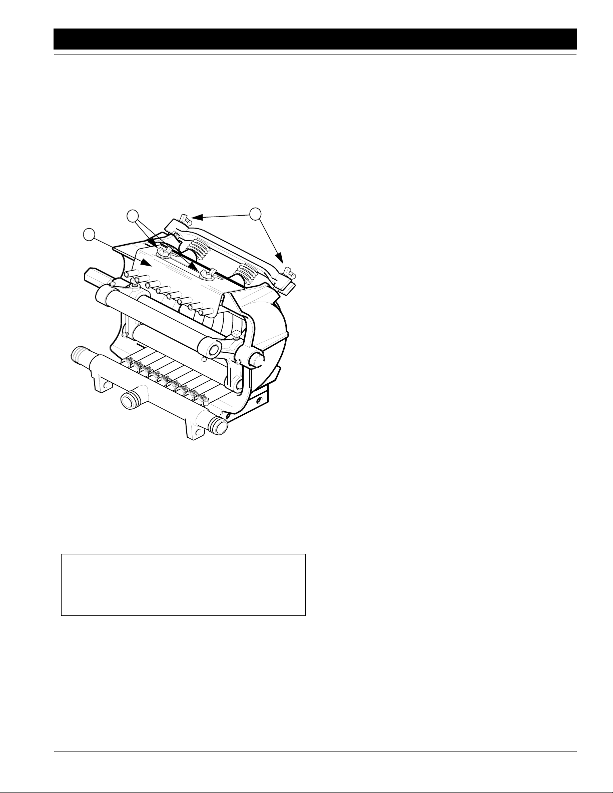
Great Plains Mfg., Inc.
Section 5 Maintenance and Lubrication
Squeeze Pumps
During periods when the pump is not being used, complete these steps to prevent hose def ormation and prolong
hose life.
Refer to Figure 5-10.
1. To release pressure against the hoses, loosen the
wing nuts (1) holding the spring bar to the pump
frame. (There are four nuts total–only tw o are shown.)
2. Loosen the wing nuts (2) on the discharge manifold (3)
and shift the manifold rearward.
3. Store out of sunlight.
2
3
12409
Figure 5-10
Relaxing Pressure on Metering Hoses
1
Storage
Store planter in a clean, dry place with all tires out of the
sun. Store planter where children do not play. If possible,
store planter inside for longer life .
1. Thoroughly clean planter, hoppers and meters. Remove any dirt and debris that can hold moisture and
cause corrosion.
2. Remove meters from hoppers. Disassemb le meters
and inspect for wear. Refer to Finger Pickup Meter,
page 40, or Brush-Type Meter, page 41. Mak e any re-
pairs required at this time. Blow excessiv e debris from
meter. Wash meters with mild soap and water. Dry
meters and spray a light coat of rust inhibitor on
meters. Reassemble and store meters in a dry place.
3. Thoroughly flush liquid herbicide system with clean
water. Disconnect from tr actor and completely dr ain
all lines and components to prevent damage from
freezing.
4. Inspect planter for worn or damaged parts. Make repairs and service during the off season.
5. Use spray paint to cov er scratches, chips and worn areas on the planter to protect the metal.
6. Adjust all drive chains for proper tension.
7. Lubricate planter at points listed under Lubrication,
page 44. Be sure to lubricate chains to prevent rusting.
8. Place 1 X 12 closing-wheel handle in the middle slot to
relieve tension on closing wheels . Mo ve T-handle for
opener springs to the lightest setting.
9. Cover planter with a tarp if stored outside.
Marker Breakaway Pr otection
The marker arm is attached to the marker body with a
5/16-inch breakaway bolt. If excessive force is put on the
marker during operation, the bolt will break, allowing the
marker arm to swing awa y r ather than cause damage to
the marker.
IMPORTANT: The breakaw a y bolt is a 5/16-b y-1 1/2inch grade 5 on planter only (GP 802-012C). If it
breaks, it must be replaced by an equiv alent grade 5
bolt to prevent marker damage.
4/12/05
PT6030 and PT8030 Pull-Type Planter 401-032M-B
43
Page 46

Section 5 Maintenance and Lubrication
Lubrication
Great Plains Mfg., Inc.
Lubrication
Legend
14946
Multipurpose
spray lube
Multipurpose
grease lube
Multipurpose
oil lube
Side Gauge Wheel Bearings
Type of Lubrication: Grease
Quantity:
Gauge Wheel Module
50
Intervals at which
lubrication is required
Seasonally
10
15052
15178
Type of Lubrication: Grease
Quantity:
As
Required
Reverser Chains
Lubricate all chains at intervals to maintain freedom at every
chain-link joint. Stiff chains will cause metering inaccuracies.
Type of Lubrication: Spray Lube
Quantity: Coat Thoroughly
PT6030 and PT8030 Pull-Type Planter 401-032M-B 4/12/05
44
Page 47

Great Plains Mfg., Inc.
Section 5 Maintenance and Lubrication
16863
As
Required
Contact Drive Chain
Lubricate all chains at intervals to maintain freedom at every
chain-link joint. Stiff chains will cause metering inaccuracies.
Type of Lubrication: Spray Lube
Quantity: Coat Thoroughly
As
Required
16872
15057
Seed and Chemical Meter Chains
Lubricate all chains at intervals to maintain freedom at every
chain-link joint. Stiff chains will cause metering inaccuracies.
Type of Lubrication: Spray Lube
Quantity: Coat Thoroughly
Seasonally
T ransport Wheel Axles
Type of Lubrication: Grease
Quantity: Fill bearing housing until grease comes out seal
4/12/05
15782
Finger Pickup Meter
To prolong the life of the finger pickup meter and increase
the planting accuracy, add a teaspoon of graphite to the
seeds every time you fill the hopper. Sprinkle the graphite
on top of the seeds, and it will filter down to lubricate the finger pickup meter.
PT6030 and PT8030 Pull-Type Planter 401-032M-B
45
Page 48

Section 5 Maintenance and Lubrication
12434
Great Plains Mfg., Inc.
10
Markers
Type of Lubrication: Grease
Quantity: Until grease begins to emerge.
10
12435
12208
Markers
Type of Lubrication: Grease
Quantity: Until grease begins to emerge.
20
Coulter Arm Housing
The grease zerk is located on the coulter arm housing.
Type of Lubrication: Grease
Quantity: Until grease begins to emerge.
Side Gauge Wheel Arms
Type of Lubrication: Grease
17811
PT6030 and PT8030 Pull-Type Planter 401-032M-B 4/12/05
46
Quantity = Three or four pumps
6
Page 49

Great Plains Mfg., Inc.
Section 5 Maintenance and Lubrication
15701
10
Dry Fertilizer Outlet Housing
Located on each outlet housing (1 each)
Type of Lubrication: Grease
Quantity: Until grease begins to emerge.
As
Required
Fertilizer Chains
Lubricate all chains at intervals to maintain freedom at every
chain link joint. Stiff chains will cause metering inaccuracies.
16864
12566
Type of Lubrication: Spray Lube
Quantity: Coat Thoroughly
Twice Daily
Squeeze Pump Main Metering Shaft
Located near ends of squeeze pump main metering shaft
(two zerks total)
Type of Lubrication: Grease
Quantity: Until grease begins to emerge.
Seasonally
4/12/05
12567
Squeeze Pump Roller Bushings
Located on the ends of the squeeze pump roller shafts (six
zerks total)
Type of Lubrication: Grease
Quantity: Until grease begins to emerge.
PT6030 and PT8030 Pull-Type Planter 401-032M-B
47
Page 50

Section 6 Options
Section 6 Options
17922
Great Plains Mfg., Inc.
Chemical Application
The optional chemical hoppers come in two versions: one
chemical meter or two chemical meters and a divider that
separates the hopper into two compartments.
Each bundle contains a hopper , meter and parts for three
different application options. With the insecticide tube, one
or two chemicals are applied directly in the furrow. With
the front diffuser (pictured left), one or two chemicals are
applied in a T-band ahead of the closing wheels. With the
rear diffuser, herbicide is applied in a 7- or 14-inch band
behind the closing wheels.
For operation inf ormation on the chemical hoppers, ref er
to Chemical Hoppers, “Operating Instructions, ” page 14.
For information on adjusting chemical-application rates,
refer to Granular Chemical Rates, “Adjustments,” page
21.
To order the chemical application options, contact your
Great Plains dealer.
Bundle Order Part Number
INSECTICIDE 6 ROW 403-096A
INSECTICIDE 8 ROW 403-097A
INSECTICIDE/HERBICIDE 6 ROW 403-100A
INSECTICIDE/HERBICIDE 8 ROW 403-101A
Unit Mounted Coulter
The optional conservation coulters mount on the row units
and till a strip for the opener disks in no- or minimum-till
conditions
For information on how to adjust the coulters, ref er to Row
Unit Adjustments, “Adjustments,” page 28. For lubrica-
tion information, refer to Lubrication, “Maintenance and
Lubrication,” page 44.
To order coulters, contact your Great Plains dealer .
Bundle Part Number
Unit Mounted Coulter,5/8-Inch Wavy, Pair 204-337A
Unit Mounted Coulter, 3/4-Inch, Pair 204-338A
12204
PT6030 and PT8030 Pull-Type Planter 401-032M-B 4/12/05
48
Page 51
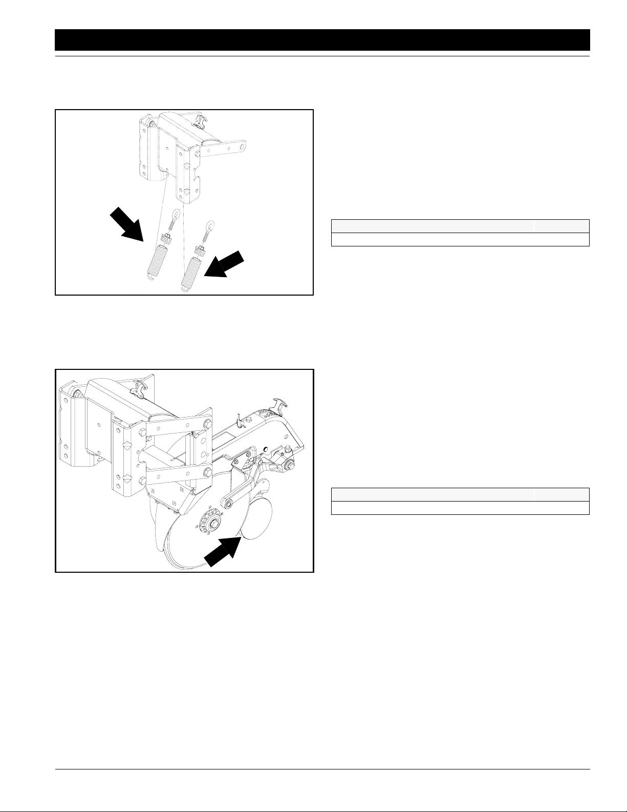
Great Plains Mfg., Inc.
Section 6 Options
17729
Heavy Duty Spring Package
Heavy-duty springs are availab le to pro vide more do wn
pressure on the row unit. Heavy-duty springs provide between 155 and 245 pounds of down pressure.
To adjust spring down pressure, refer to Down Pressure ,
“Adjustments,” page 28.
To order heavy-duty springs for your row units , contact
your Great Plains dealer .
Package Part Number
Heavy-Duty Spring Package 406-006S
17892
Seed-Lok Firming Wheels
The optional spring-loaded Seed-Lok firming wheels
press seed directly into the bottom of the seed bed. The
Seed-Lok option provides more ev en emergence since
seeds are planted and firmed at the same depth.
To lock up the firming wheels in wet conditions, refer to
Seed-Lok Lock Up, “Adjustments,” page 31.
To order Seed-Lok firming wheels, contact your Great
Plains dealer.
Package Part Number
SEED LOK 98 ROW UNIT 404-093K
4/12/05
PT6030 and PT8030 Pull-Type Planter 401-032M-B
49
Page 52

Section 6 Options
15727
Great Plains Mfg., Inc.
Liquid Fertilizer Option
The fertilizer option is a complete system which allows you
to band liquid fertilizer on either 6 rows or 8 rows. The 6
row option contains two 150 gallon liquid tanks and the 8
row option contains two 200 gallon liquid tanks. Also in
cluded are mounts, an eight row squeeze pump, and the
plumbing hardware to tie together all components.
The squeeze pump features a heavy-duty, cast-iron body
to hold it true when mounted on equipment that flexes ov er
rough terrain. The floating, aluminum-alloy bac k plate pro
vides a positive shutoff when the pump stops.
For additional information refer to “Important Safety In-
formation,” page 1, Liquid Fertilizer Option, “Operating
Instructions,” page 13, Liquid Fertilizer Attachment, “Adjustments,” page 26, Liquid Fertilizer Option, “Maintenance and Lubrication,” page 42.
To order liquid fertilizer option, contact your Great Plains
dealer.
Package Part Number
Liquid Fertilizer, 6 row 407-017A
Liquid Fertilizer, 8 row 407-018A
-
-
17933
17932
Fertilizer Coulters
The optional fertilizer coulters are for use in conjunction
with the liquid or dry fertilizer option. The Vantage I
coulters are for use with low-pressure, liquid-fertilizer injection. The Vantage II coulter is available for use with
liquid or dry fertilizer.
To order fertilizer coulters, contact your Great Plains
dealer.
Package Part Number
Pair of Vantage I Coulters, 3/4-Inch Wavy 407-043A
Pair of Vantage I Coulters, 5/8-Inch Wavy 407-044A
Pair of Vantage II Coulter, Liquid 407-046A
Pair of Vantage II Coulter, Dry 407-045A
PT6030 and PT8030 Pull-Type Planter 401-032M-B 4/12/05
50
Page 53

Great Plains Mfg., Inc.
Section 6 Options
Zone Tillage Coulters
The optional tillage coulters mount on the planter toolbar.
The coulters have a heavy-duty swivel casting and spring,
a double-lipped grease seal and tapered roller bearings.
Each bundle includes one right-hand an one left-hand
coulter.
To order zone tillage coulters, contact your Great Plains
dealer.
Package Part Number
Pair of Zone Coulter, 3/4-Inch Wavy 407-040A
Pair of Zone Coulter, 5-8-Inch Wavy 407-041A
17934
15814
Terra Tine
The terra tine option helps create a trash-free zone for
seed placement. Mounted on the planter toolbar, the terra
tine sweeps create very little trenching.
To order terra tine for your planter, contact your Great
Plains dealer.
Package Part Number
Terra Tine Pair, Frame Mount 404-098A
4/12/05
PT6030 and PT8030 Pull-Type Planter 401-032M-B
51
Page 54
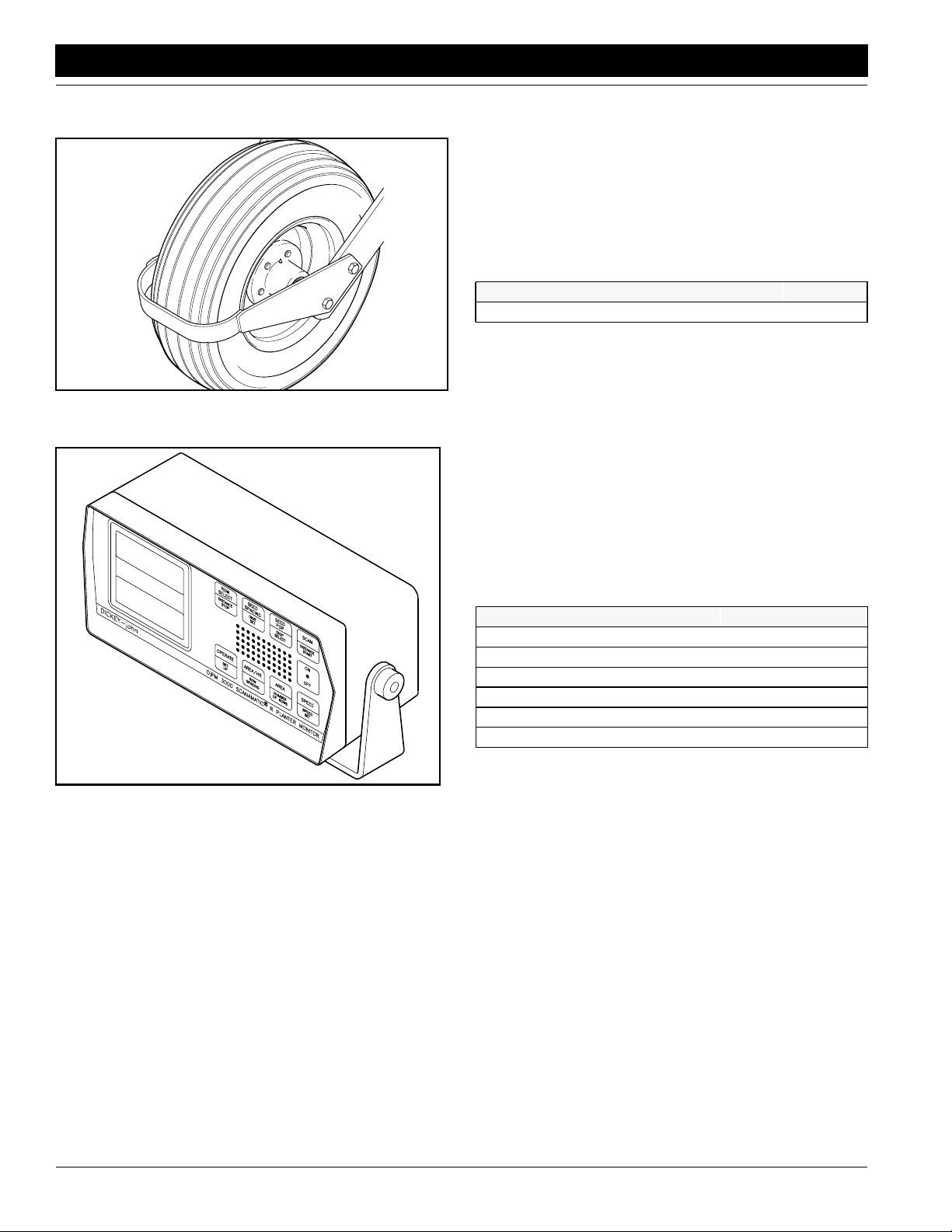
Section 6 Options
Great Plains Mfg., Inc.
Gauge Wheel Tire Scrapers
In some soil types, you may need to use optional tire
scrapers. The scrapers prev ent e xcess mud from building
up on the transport tires so the contract-drive tire can operate properly. Adjust the scraper so it does not contact
the tire.
To order tire scrapers, contact your Great Plains dealer.
Package Part Number
Tire scraper for one wheel 402-072K
15027
Monitor
The DICKEY-john® Monitor Option is a micro-processorbased, planter-monitoring system. If seed is not going to
the ground, the monitor will sound and indicate which row
unit has stopped planting. The system also provides information for seed spacing, seed population, area, ground
speed and projected area per hour.
To order the monitor, contact your Great Plains dealer.
15848
Bundle Part Number
DICKEY-john 1000, 6-Row 403-047K
DICKEY-john 3000 with Radar, 6-Row 403-063K
DICKEY-john 3000 without Radar, 6-Row 403-049K
DICKEY-john 1000, 8-Row 403-050K
DICKEY-john 3000 with Radar, 8-Row 403-064K
DICKEY-john 3000 without Radar, 8-Row 403-051K
PT6030 and PT8030 Pull-Type Planter 401-032M-B 4/12/05
52
Page 55

Great Plains Mfg., Inc.
Section 7 Specifications and Capacities
Section 7 Specifications and Capacities
Type Pull Type
Row Spacing 30 inches
Rows per Unit 68
Weight 5,000 pounds* 6,875 pounds*
Drive Ground drive with contact drive wheel
Transmission End mounted
Frame Construction 7-by-7-inch; 5/16-inch wall
Transport Width 15 feet 16 feet
Length 6 feet
Tires Gauge Wheel: 9.5 L X 15; Contact Drive Wheel: 13-6.50 X 6
Tractor Requirements 80 - 120 horsepower 100 - 140 horsepower
Row Specifications
Down-Pressure Springs, Standard Package Five-setting, quick-change springs; 1/4-diameter wire; 85 to 155 pounds
Opener 15-inch double disks, double-ground and offset
Unit Body Shank welded, 7-gauge sheet metal; hopper support plate, 12-gauge sheet
Parallel Linkage 1/2 x 2 arms, high-carbon steel
Depth Wheels 4 x 16
Closing Wheels or Disks 1 x 12 double-v closing wheels or 6.5-inch chevron wheel with closing disks
Depth Control 0 to 4 inches,1/4-inch increments
Hopper Capacity 2 bushels
NOTE: Horsepower requirements will vary with field conditions, terrain and
planter options.
down force
metal
*With markers and fertilizer option
Optional Liquid Squeeze Pump
Maximum speed 125 rpm
Maximum pressure 5 psi
Output per revolution 5/16-inch hose: 0.58 gpm; 1/2-inch hose: 1.4 gpm
4/12/05
PT6030 and PT8030 Pull-Type Planter 401-032M-B
53
Page 56

Section 7 Specifications and Capacities
Great Plains Mfg., Inc.
Specification Drawing
14953
PT6030 and PT8030 Pull-Type Planter 401-032M-B 4/12/05
54
Page 57

Great Plains Mfg., Inc.
Appendix
Appendix
Torque Values Chart for Common Bolt Sizes
Bolt Head Identification
Bolt Size
(Inches)
1
in-tpi
1/4" - 20 7.4 5.6 11 8 16 12 M 5 X 0.8436597
1/4" - 28 8.5 6 13 10 18 14 M 6 X 1 7 5 11 8 15 11
5/16 - 18 15 11 24 17 33 25 M 8 X 1.25 17 12 26 19 36 27
5/16" - 24 17 13 26 19 37 27 M 8 X 1 18 13 28 21 39 29
3/8" - 16 27 20 42 31 59 44 M10 X 1.5 33 24 52 39 72 53
3/8" - 24 31 22 47 35 67 49 M10 X 0.75 39 29 61 45 85 62
7/16" - 14 43 32 67 49 95 70 M12 X 1.75 58 42 91 67 125 93
7/16" - 20 49 36 75 55 105 78 M12 X 1.5 60 44 95 70 130 97
1/2" - 13 66 49 105 76 145 105 M12 X 1 90 66 105 77 145 105
1/2" - 20 75 55 115 85 165 120 M14 X 2 92 68 145 105 200 150
9/16" - 12 95 70 150 110 210 155 M14 X 1.5 99 73 155 115 215 160
9/16" - 18 105 79 165 120 235 170 M16 X 2 145 105 225 165 315 230
5/8" - 11 130 97 205 150 285 210 M16 X 1.5 155 115 240 180 335 245
5/8" - 18 150 110 230 170 325 240 M18 X 2.5 195 145 310 230 405 300
3/4" - 10 235 170 360 265 510 375 M18 X 1.5 220 165 350 260 485 355
3/4" - 16 260 190 405 295 570 420 M20 X 2.5 280 205 440 325 610 450
7/8" - 9 225 165 585 430 820 605 M20 X 1.5 310 230 650 480 900 665
7/8" - 14 250 185 640 475 905 670 M24 X 3 480 355 760 560 1050 780
1" - 8 340 250 875 645 1230 910 M24 X 2 525 390 830 610 1150 845
1" - 12 370 275 955 705 1350 995 M30 X 3.5 960 705 1510 1120 2100 1550
1-1/8" - 7 480 355 1080 795 1750 1290 M30 X 2 1060 785 1680 1240 2320 1710
1 1/8" - 12 540 395 1210 890 1960 1440 M36 X 3.5 1730 1270 2650 1950 3660 2700
1 1/4" - 7 680 500 1520 1120 2460 1820 M36 X 2 1880 1380 2960 2190 4100 3220
1 1/4" - 12 750 555 1680 1240 2730 2010
1 3/8" - 6 890 655 1990 1470 3230 2380
1 3/8" - 12 1010 745 2270 1670 3680 2710
1 1/2" - 6 1180 870 2640 1950 4290 3160
1 1/2" - 12 1330 980 2970 2190 4820 3560
Grade 2 Grade 5
N · m2ft-lb3N · m ft-lb N · m ft-lb mm x pitch
Torque tolerance + 0%, -15% of torquing values. Unless otherwise specified use torque values listed above.
Grade 8
Bolt Size
(Metric)
4
N · m ft-lb N · m ft-lb N · m ft-lb
1
in-tpi = nominal thread dia.in inches-threads per inch
4
mm x pitch = nominal thread dia. in millimeters x thread pitch
Bolt Head Identification
5.8 8.8 10.9
Class 5.8 Class 8.8 Class 10.9
2
N· m = newton-meters
3
ft-lb= foot pounds
4/12/05
PT6030 and PT8030 Pull-Type Planter 401-032M-B
55
Page 58

Appendix
Metric Conversion Chart
Multiply By To Get
inches in.
inches in.
feet ft.
miles per hour mph
pounds lbs.
bushels bu.
gallons gal
pounds per
square inch psi
inch pounds in. lbs.
foot pounds ft. lbs.
centimeters cm
millimeters mm
centimeters cm
hectares ha
kilometers per hour
kilograms kg
liters l
liters l
kilopascals kPa
(100 kPa = 1 bar)
Newtons-meters N.m
Newtons-meters N.m
x 2.54 = centimeters cm
x 25.4 = millimeters mm
x 30.48 = centimeters cm
x 1.609 = kilometers per hour
x 0.453 = kilograms kg
x 35.238 = liters l
x 3.785 = liters l
x 6.894 = kilopascals kPa
x 0.113 = Newtons-meters N.m
x 1.356 = Newtons-meters N.m
x 394 = inches in.
x 0394 = inches in.
x 0328 = feet ft.
x 2.469 = acres
x 0.621 = miles per hour mph
kmph
x 2.208 = pounds lbs.
x 0.028 = bushels bu.
x 0.264 = gallons gal.
x 0.145 = pounds per
x 8.85 = inch pounds in lb.
x 0.738 = foot pounds ft lb
kmph
(100 kPa = 1 bar)
square inch psi
Great Plains Mfg., Inc.
NOTE:All tires are warranted bythe original manufacturer of the tire. Tire warranty inf ormation can be found in
the brochures included with your Operator’s and Parts
Manuals or online at the manufacturer’s websites. For
service assistance or information, contact your nearest
Authorized Farm Tire Retailer.
Manufacturer Website
Titan www.titan-intl.com
Goodyear www.goodyearag.com
Firestone www.firestoneag.com
Tire Inflation Chart
Tire Size Inflation PSI Tire Size Inflation PSI
7.50 x 20" 4-Ply Drill Rib 28 11L x 15" 6-Ply Rib Implement 28
9.0 x 22.5 10-Ply Highway Service 70 70 11L x 15" 12-Ply Rib Implement 52
9.0 x 24" 8-Ply Rib Implement 40 12.5L x 15" 8-Ply Rib Implement 36
9.5L x 15" 6-Ply Rib Implement 32 12.5L x 15" 10-Ply Rib Implement 44
9.5L x 15" 8-Ply Rib Implement 44 16.5L x 16.1" 10-Ply Rib Implement 36
9.5L x 15" 12-Ply Rib Implement 60 41 x 15" x 18 - 22-Ply Rib Implement 44
13 x 5.00-6 4-ply T urf Saver 40 13-6.50 x 6 40
PT6030 and PT8030 Pull-Type Planter 401-032M-B 4/12/05
56
Page 59

Great Plains Manufacturing, Inc.
Corporate Office: PO. Box 5060
Salina, Kansas 67402-5060 USA
 Loading...