

Page 1
Operator’s Manual
PT6030 and PT8030
Pull-Type Planter
Model Serial No.
PT6030 U1049 through U1068
PT8030 V1013 and V1014
Manufacturing, Inc.
P.O. Box 5060 ● Salina, Kansas 67402-5060
Read the operator’s manual entirely. When you see this symbol, the subsequent in-
!
structions and warnings are serious - follow without exception. Your life and the lives of
others depend on it!
© Copyright 1999 Printed
3/9/99
15193
Cover illustration may show optional equipment not supplied with standard unit.
401-032M-A
Page 2

Table of Contents
Table of Contents
Great Plains Mfg., Inc.
Important Safety Information . . . . . . . . . . . . . . . . . 1
Safety Notations . . . . . . . . . . . . . . . . . . . . . . . . . 1
Safety Rules . . . . . . . . . . . . . . . . . . . . . . . . . . . . 1
Personal Safety Equipment . . . . . . . . . . . . . . . . . 4
Safety Labels. . . . . . . . . . . . . . . . . . . . . . . . . . . . 5
Introduction . . . . . . . . . . . . . . . . . . . . . . . . . . . . . . . 9
Description of Unit . . . . . . . . . . . . . . . . . . . . . . . . 9
Using This Manual . . . . . . . . . . . . . . . . . . . . . . . . 9
Owner Assistance . . . . . . . . . . . . . . . . . . . . . . . . 9
Section 1 Planter Preparation and Setup. . . . . . . 10
Initial Preparation of the Planter . . . . . . . . . . . . 10
Leveling the Planter. . . . . . . . . . . . . . . . . . . . . . 10
Ridge Planting . . . . . . . . . . . . . . . . . . . . . . . . . . 11
Liquid Fertilizer Option. . . . . . . . . . . . . . . . . . . . 11
Section 2 Operation . . . . . . . . . . . . . . . . . . . . . . . . 12
Basic Planting Operation . . . . . . . . . . . . . . . . . . 12
Rephasing the Hydraulic System . . . . . . . . 12
Seed Meter and Hopper Operation . . . . . . . . . . 12
Chemical Meters and Hopper . . . . . . . . . . . . . . 13
Liquid Fertilizer Operation . . . . . . . . . . . . . . . . . 13
Squeeze Pump Hose Alignment . . . . . . . . . 14
Marker Operation. . . . . . . . . . . . . . . . . . . . . . . . 14
Transporting . . . . . . . . . . . . . . . . . . . . . . . . . . . . 14
Section 3 Adjustments . . . . . . . . . . . . . . . . . . . . . 15
Planting Rate . . . . . . . . . . . . . . . . . . . . . . . . . . . 15
Transmission Adjustment . . . . . . . . . . . . . . 15
2-to-1 Drive Reduction . . . . . . . . . . . . . . . . 15
Checking Planting Population . . . . . . . . . . . 15
Planting Rates for Finger Pickup Corn Meters . 16
Planting Rates for Brush Meters . . . . . . . . . . . . 17
Granular Chemical Rates . . . . . . . . . . . . . . . . . 19
Conversion from Broadcast to Row Coverage19
Recalibrating Granular Chemical Meters . . 20
Granular Chemical Rate Charts . . . . . . . . . . . . 21
Clay Granules, Herbicide . . . . . . . . . . . . . . 21
Clay Granules, Insecticide. . . . . . . . . . . . . . 22
Sand Granules, Herbicide and Insecticide . 23
Liquid Fertilizer Attachment . . . . . . . . . . . . . . . . 24
Dry Fertilizer Attachment . . . . . . . . . . . . . . . . . . 24
Dry Fertilizer Low Rate Setting . . . . . . . . . . 25
Dry Fertilizer High Rate Setting. . . . . . . . . . 25
Opener Adjustments . . . . . . . . . . . . . . . . . . . . . 26
Opener Depth . . . . . . . . . . . . . . . . . . . . . . . 26
Down Force Spring Adjustment . . . . . . . . . . 26
Row Unit Coulter Adjustment. . . . . . . . . . . . 26
1 x 12 Closing Wheel Adjustments . . . . . . . 27
Closing Disk Tube Shield . . . . . . . . . . . . . . . 28
Closing Disk Adjustment . . . . . . . . . . . . . . . 28
Seed-Lok . . . . . . . . . . . . . . . . . . . . . . . . . . . 28
Marker Adjustments . . . . . . . . . . . . . . . . . . . . . . 29
Tire Scraper . . . . . . . . . . . . . . . . . . . . . . . . . . . . 30
Meter Drive Adjustments . . . . . . . . . . . . . . . . . . 30
Section 4 Troubleshooting . . . . . . . . . . . . . . . . . . . 32
Section 5 Maintenance and Lubrication . . . . . . . . 35
Install Cylinder Stops . . . . . . . . . . . . . . . . . . . . . 35
Replacing Shear Pins. . . . . . . . . . . . . . . . . . . . . 35
Fasteners . . . . . . . . . . . . . . . . . . . . . . . . . . . . . . 36
Ratchet Drive (8 Row Only) . . . . . . . . . . . . . . . . 36
Finger Pickup Meter . . . . . . . . . . . . . . . . . . . . . . 36
Openers . . . . . . . . . . . . . . . . . . . . . . . . . . . . . . . 38
Chain Tension. . . . . . . . . . . . . . . . . . . . . . . . . . . 38
Chemical Hoppers . . . . . . . . . . . . . . . . . . . . . . . 40
Cleaning Liquid Fertilizer Tanks . . . . . . . . . . . . . 40
Squeeze Pumps . . . . . . . . . . . . . . . . . . . . . . . . . 40
Marker Breakaway Protection . . . . . . . . . . . . . . 40
Storage. . . . . . . . . . . . . . . . . . . . . . . . . . . . . . . . 41
Lubrication . . . . . . . . . . . . . . . . . . . . . . . . . . . . . 42
Section 6 Options . . . . . . . . . . . . . . . . . . . . . . . . . . 46
Marker Attachment . . . . . . . . . . . . . . . . . . . . . . . 46
Coulter Option . . . . . . . . . . . . . . . . . . . . . . . . . . 46
Seed Lok . . . . . . . . . . . . . . . . . . . . . . . . . . . . . . 47
6.5 x 12 Press Wheel w/Closing Disk. . . . . . . . . 47
Spring Package . . . . . . . . . . . . . . . . . . . . . . . . . 47
16” Wheel Cover. . . . . . . . . . . . . . . . . . . . . . . . . 48
1 x 12 Closing Wheel . . . . . . . . . . . . . . . . . . . . . 48
Liquid Fertilizer Option . . . . . . . . . . . . . . . . . . . . 48
Insecticide Option. . . . . . . . . . . . . . . . . . . . . . . . 49
Insecticide & Herbicide Option . . . . . . . . . . . . . . 49
Dry Fertilizer Option . . . . . . . . . . . . . . . . . . . . . . 49
Section 7 Specifications and Capacities . . . . . . . 50
Appendix . . . . . . . . . . . . . . . . . . . . . . . . . . . . . . . . . 52
Tire Inflation Chart . . . . . . . . . . . . . . . . . . . . . . . 52
Torque Values Chart for Common Bolt Sizes. . . 52
Metric Conversion Chart. . . . . . . . . . . . . . . . . . . 53
© Copyright 1998 All rights Reserved
Great Plains Manufacturing, Inc. provides this publication “as is” without warranty of any kind, either expressed or implied. While every precaution has been taken in the preparation
of this manual, Great Plains Manufacturing, Inc. assumes no responsibility for errors or omissions. Neither is any liability assumed for damages resulting from the use of the information contained herein. Great Plains Manufacturing, Inc. reserves the right to revise and improve its products as it sees fit. This publication describes the state of this product at the
time of its publication, and may not reflect the product in the future.
The following are trademarks of Great Plains Mfg., Inc.: Application Systems, Ausherman, Land Pride, Great Plains
All other brands and product names are trademarks or registered trademarks of their respective holders.
Great Plains Manufacturing, Incorporated Trademarks
Printed in the United States of America.
PT6030 and PT8030 Pull-Type Planter 401-032M-A 10/10/12Great Plains Mfg., Inc.
Page 3
Important Safety Information
Important Safety Information
For your safety and to develop a better understanding of
your equipment, thoroughly read this manual before oper
ation.
Safety Notations
The safety alert symbol indicates that there is a potential
hazard to personal safety involved and extra safety pre
cautions must be taken. When you see this symbol, be
alert and carefully read the message that follows it. In ad
dition to design and configuration of equipment; hazard
control and accident prevention are dependent upon the
awareness, concern, prudence and proper training of per
sonnel involved in the operation, transport, maintenance
and storage of equipment.
Watch for the following safety notations throughout
your operator’s manual:
!
DANGER!
Indicates an imminently hazardous situation which, if not
avoided, will result in death or serious injury. This signal word
is limited to the most extreme situations.
!
WARNING!
Indicates a potentially hazardous situation which, if not avoided, could result in death or serious injury.
!
CAUTION!
Indicates a potentially hazardous situation which, if not avoided, may result in minor or moderate injury. It may also be used
to alert against unsafe practices
Safety Rules
These rules and instructions
must be reviewed at least annually
by all operators!
!
-
-
-
-
!
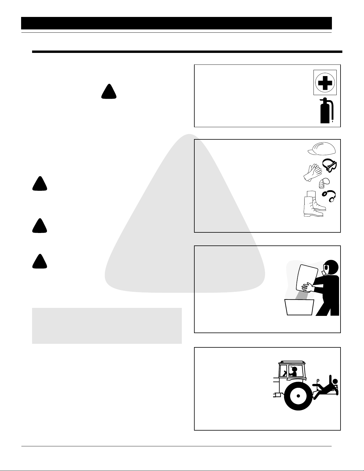
Prepare for Emergencies
Be prepared if a fire starts.
Keep a first aid kit and fire extinguisher
handy.
Keep emergency numbers for doctors, ambulance service, hospital, and fire department near your telephone.
Wear Protective Equipment
Wear clothing and safety equipment appropriate for the job. Avoid loose fitting
clothing
Prolonged exposure to loud noise can
cause hearing impairment or hearing
loss. Wear suitable hearing protection
such as earmuffs or earplugs.
Operating equipment safely requires the
full attention of the operator. Avoid wearing radio headphones while operating
machinery.
Handle Chemicals Properly
Agricultural chemicals can be
dangerous. Improper selection
or use can seriously injure persons, animals, plants, soil or other property. BE SAFE. Handle all
chemicals with care. Follow the
instructions on the container label. Precautions should be taken
to prevent exposure. Protective
clothing and equipment is to be
worn
Great Plains Mfg., Inc.
Most accidents are the result of negligence and carelessness, caused by failure of the operator to follow safety
precautions. Even though your implement is designed
with many built-in safety features, the following precau
tions are mandatory to prevent such accidents.
Make sure everyone that uses this machine has read the operator’s manual and understands how to operate it safely.
This operator’s manual is considered a part of the implement and should remain so when loaned or sold.
PT6030 and PT8030 Pull-Type Planter 401-032M-A 10/10/12
1
-
Keep Riders Off Machinery
A rider on machinery is subject to injury such as being
struck by foreign objects or
being thrown off the machine. A rider obstructs the
operator’s view, resulting in
unsafe machine operation.
Keep riders off any machinery while in operation. Allow only skilled persons to operate machinery.
Page 4

Great Plains Mfg., Inc.
Important Safety Information
Use Safety Lights and Devices
Slow moving tractors, self-propelled
equipment and towed implements or at-
tachments can create a hazard when
driven on public roads, and are difficult to
see, especially at night.
Flashing warning lights and turn signals
are recommended whenever driving on
public roads. Use the lights and devices
provided with your machine.
Keep safety signs and lights in good condition. Replace
any missing or damaged items.
Transport Machinery Safely
Comply with state and local laws when
transporting machinery.
Maximum transport speed for planter is 20
mph. DO NOT EXCEED. Never travel at a
speed which does not allow adequate con-
trol of steering and stopping.
Braking from transport speed can cause a
towed load to swerve and upset. Reduce
speed if towed load is not equipped with
brakes.
Use the following recommended speed-
weight ratios as a guideline:
● Maximum speed of 20 mph when weight
of towing load is less than or equal to the
weight of your tractor.
● Reduce speed to 10 mph when weight of towed load
is up to double the weight of your tractor.
● Do not tow a load which is more than double the
weight of your tractor.
Use a Safety Chain
A safety chain will help control drawn machinery should
it separate from the tractor drawbar.
Use a chain with the strength rating equal to or greater
than the gross weight of the towed machinery.
Attach the chain to the tractor drawbar support or other
specified anchor
location. Allow
only enough
slack in the chain
to permit turning.
Do not use safe-
ty chain for tow-
ing.
Avoid High Pressure Fluids Hazard
Escaping hydraulic oil can have ex-
tremely high pressure which can
penetrate the skin causing serious
injury.
Avoid this hazard by relieving all hy-
draulic pressure before disconnect-
ing any lines. Be sure all connections are tight before
applying pressure.
Protect hands and body from high pressure fluids. Use
a piece of cardboard or wood to detect leaks.
If an injury is caused by escaping hydraulic fluid. SEE A
DOCTOR IMMEDIATELY! The fluid must be surgically
removed within a few hours or gangrene will result
Practice Safe Maintenance
Understand maintenance proce-
dure before doing work. When ser-
vicing machine use proper tools
and equipment. Refer to operator’s
manual.
Keep hands, feet, and clothing
away from power-driven parts. Dis-
engage all power and relieve pres-
sure.
Lower machine to the ground. Stop
tractor engine and remove the key.
Allow machine to cool before ser-
vicing.
Keep the area clean and dry.
Securely support machine compo-
nents that will be raised during service.
Disconnect battery ground cable (-) before servicing or
adjusting electrical systems or before welding on ma-
chine.
Make sure all parts are properly installed and in good
condition. Fix any damage immediately and replace
worn or broken parts. Remove buildup of grease, oil or
debris.
Prior To Operation
1. Practice safety by always thinking before acting.
2. Make sure safety rules are understood before operating machine or tractor.
3. Loose fitting clothing should not be worn as it may catch in
moving parts.
4. Never attempt to operate the implement unless you are in
the driver's seat.
5. Never dismount from a moving tractor.
10/10/12
PT6030 and PT8030 Pull-Type Planter 401-032M-A
2
Page 5

Important Safety Information
Great Plains Mfg., Inc.
6. Do not leave the tractor or the implement unattended with
the engine running.
7. Do not stand between the tractor and the implement during
hitching.
During Operation
1. Never allow the planter to be operated by anyone who is un-
familiar with the operation of all functions of the unit. All
operators should read and thoroughly understand the instructions given in this manual prior to moving the unit.
2. Never permit any persons other than the operator to ride on
the tractor.
3. Regulate your speed to the field conditions, maintaining
complete control at all times.
4. Always lower the implement and shut off the tractor engine
before making any adjustments.
5. Do not grease or oil machine while it is in operation.
6. Always make sure there are no persons near the planter
when the marker assemblies are in operation.
7. Watch for obstructions such as wires, tree limbs etc., when
folding markers.
8. If a hydraulic leak develops, correct it immediately. Escaping hydraulic oil can have extremely high pressure. A
stream of high pressure oil may easily penetrate the skin as
with modern needless vaccination equipment - but with the
exception that hydraulic fluid may cause blood poisoning. It
is imperative that the connections are tight and that all lines
and pipes are in good condition. If an injury is caused by the
escaping hydraulic fluid, see a doctor at once!
After Operation
1. Detach and store implements in an area where children nor-
mally do not play. Stabilize implements by using suitable
supports and block wheels.
During Maintenance
1. After repairing or adjusting, make sure all tools and parts
are removed from the implement before attempting to operate it.
2. Never work under a raised planter.
3. Disk edges are sharp! Be careful when working in this area.
4. Use a piece of cardboard or wood to detect leaks of hydraulic oil under pressure.
5. Be sure to relieve all hydraulic pressure before disconnection any lines or pipes between the implement and the tractor hydraulic system. Keep all guards and shields in place.
Transporting
1. Before transporting make sure the hitch is securely attached
to the draw bar of the tractor and the safety chain is connected.
2. Be alert to traffic when crossing or operating near road-
ways. Always maintain complete control of the machine.
Know your state and local laws concerning highway safety
and regulations. Comply with these laws when transporting
machinery.
3. Do not exceed 20 mph when transporting. Transport only
with a farm tractor of sufficient size and horse power. See
Tractor Preparation in “Section 2 Operation” on
page 12.
4. Always make sure flashing safety lights, slow moving vehi-
cle emblem, and reflectors are in place and visible prior to
transporting the machine on public roads, when required.
5. Do not transport at night or during other periods of poor
visibility.
Tire Handling & Repair
1. Tire changing can be dangerous and should be preformed
by trained personnel using the correct tools and equipment.
2. Do not re-inflate a tire that has been run flat or seriously
under inflated. Have it checked by qualified personnel.
3. When removing and installing wheels, use wheel handling
equipment adequate for the weight involved.
Agricultural Chemicals
1. Agricultural chemicals can be dangerous. Always select the
correct chemical for the job. Improper usage of fertilizers,
fungicides, herbicides, insecticides, and pesticides could
cause injury to all living things.
2. Always read instructions supplied by the manufactures be-
fore opening chemical containers. Read and follow instructions supplied by the chemical manufacturer carefully
before each use.
3. Apply the same precautions when adjusting, servicing,
cleaning, or storing this implement as you would when putting chemicals into it.
4. Inform anyone who may come in contact with chemicals, or
an implement with chemicals, of any potential hazard or
safety precaution that should be observed.
5. Avoid inhaling smoke from any type of chemical fire.
6. Store or dispose of all unused chemicals as specified by the
chemical manufacturer.
PT6030 and PT8030 Pull-Type Planter 401-032M-A 10/10/12
3
Page 6
Great Plains Mfg., Inc.
Important Safety Information
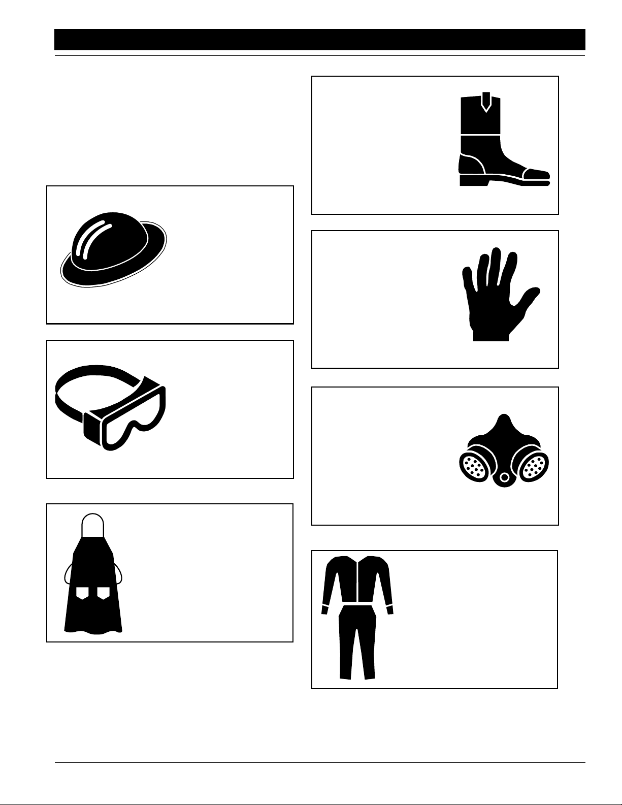
Personal Safety Equipment
Great Plains advises all users of chemical pesticides or
herbicides to use the following personal safety equipment. Always follow the chemical label instructions, your
safety and the effectivity of the product depends upon
your actions.
Waterproof, widebrimmed hat
Waterproof boots or foot
coverings
Waterproof, unlined
gloves. Neoprene gloves
are recommended.
Face shield, goggles or
full face respirator. Goggles with side shields or a
full face respirator is required if handling or
applying dusts, wettable
powders, or granules or if
being exposed to spray
mist.
Waterproof apron
Cartridge-type respirator
approved for pesticide vapors unless label specifies
another type of respirator.
Cloth coveralls/outer clothing
changed daily; waterproof
items if there is a chance of becoming wet with spray
10/10/12
PT6030 and PT8030 Pull-Type Planter 401-032M-A
4
Page 7
Important Safety Information
Safety Labels
Your implement comes equipped with all safety labels in place.
They were designed to help you safely operate your implement.
1. Read and follow label directions.
2. Keep all safety labels clean and legible.
3. Replace all damaged or missing labels. Order new labels
from your Great Plains dealer. Refer to this section for
proper label placement.
Great Plains Mfg., Inc.
4. When ordering new parts or components, also request corresponding safety labels.
5. To install new labels:
a. Clean the area on which the label is to be placed.
b. Peel backing from label. Press firmly on surface,
being careful not to cause air bubbles under label.
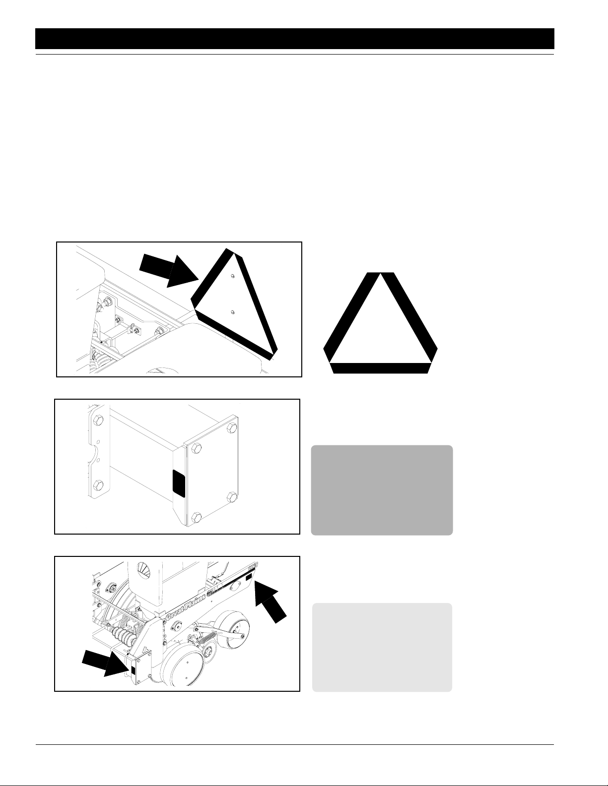
14945
12356
818-003C
Slow Moving Vehicle Label
818-230
Red Reflector
14955
PT6030 and PT8030 Pull-Type Planter 401-032M-A 10/10/12
5
818-229C
Amber Reflector
Page 8
Great Plains Mfg., Inc.
Important Safety Information
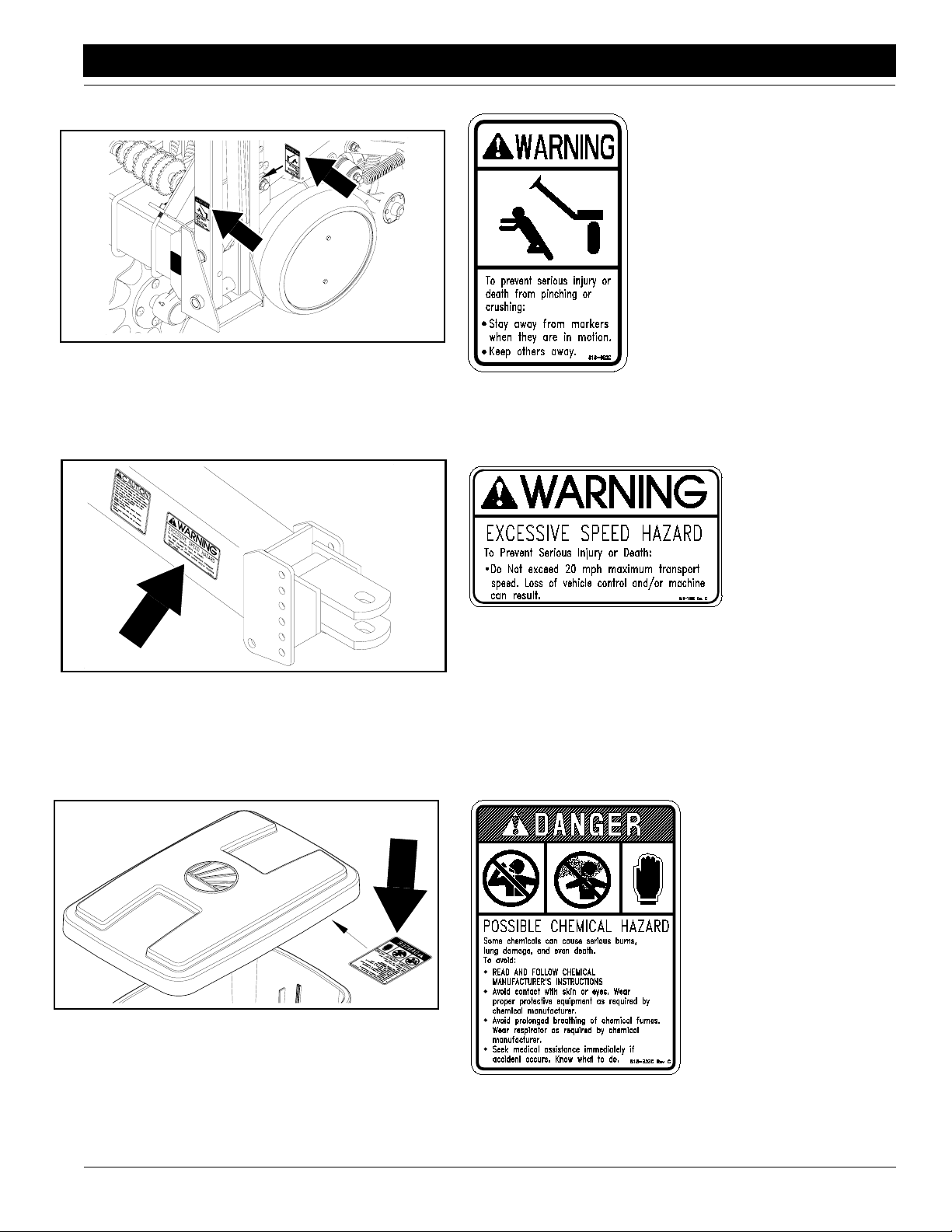
14919
14920
818-682C
Pinch/Crush Warning
818-188C
Transport Speed Warning
10/10/12
12359
818-323C
Ag Chemicals Caution
Located inside the
chemical lid
PT6030 and PT8030 Pull-Type Planter 401-032M-A
6
Page 9
Important Safety Information
Great Plains Mfg., Inc.
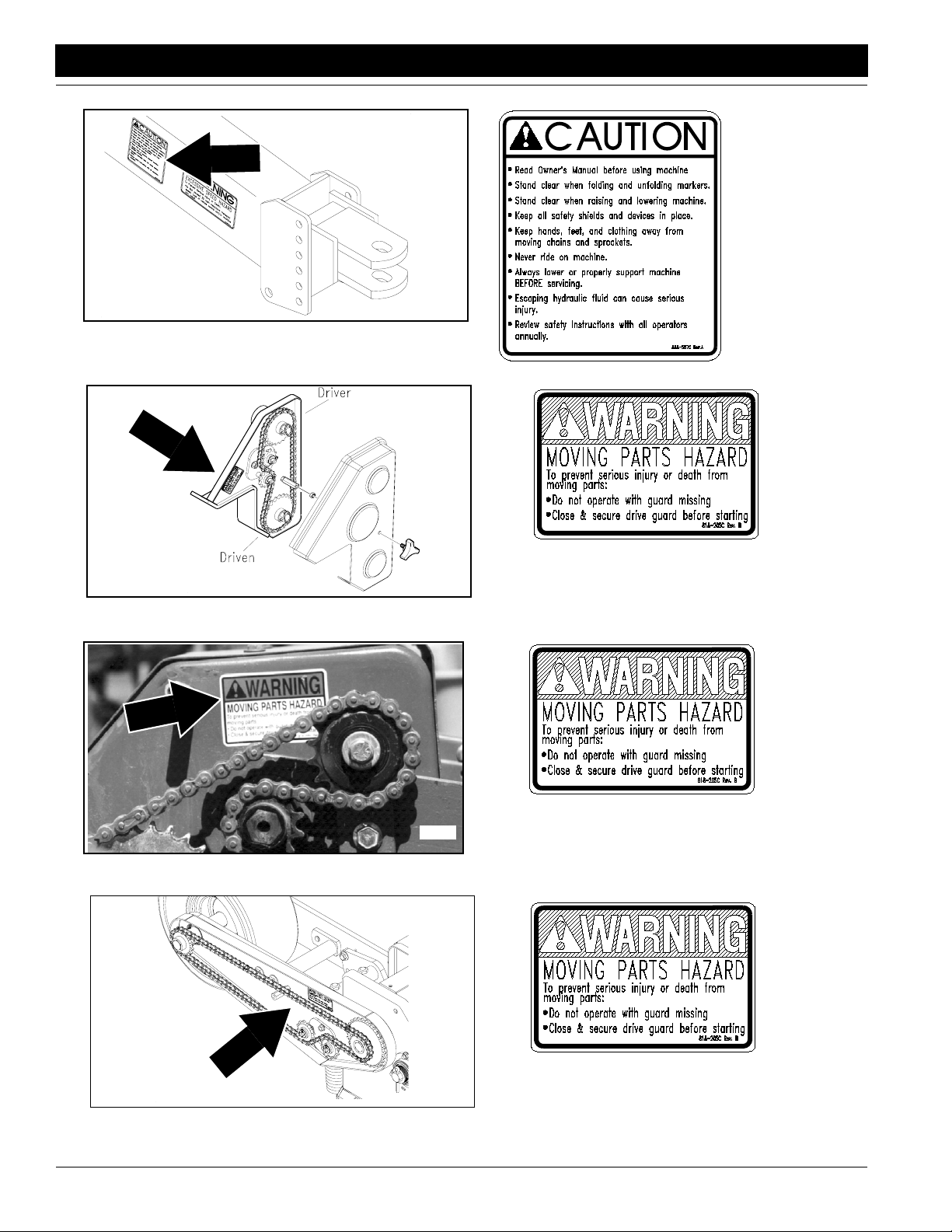
14920
818-587C
Operational Caution
16861
15720
818-205C
Moving Parts Warning
818-205C
Moving Parts Warning
16863
PT6030 and PT8030 Pull-Type Planter 401-032M-A 10/10/12
7
818-205C
Moving Parts Warning
Page 10
Great Plains Mfg., Inc.
Important Safety Information
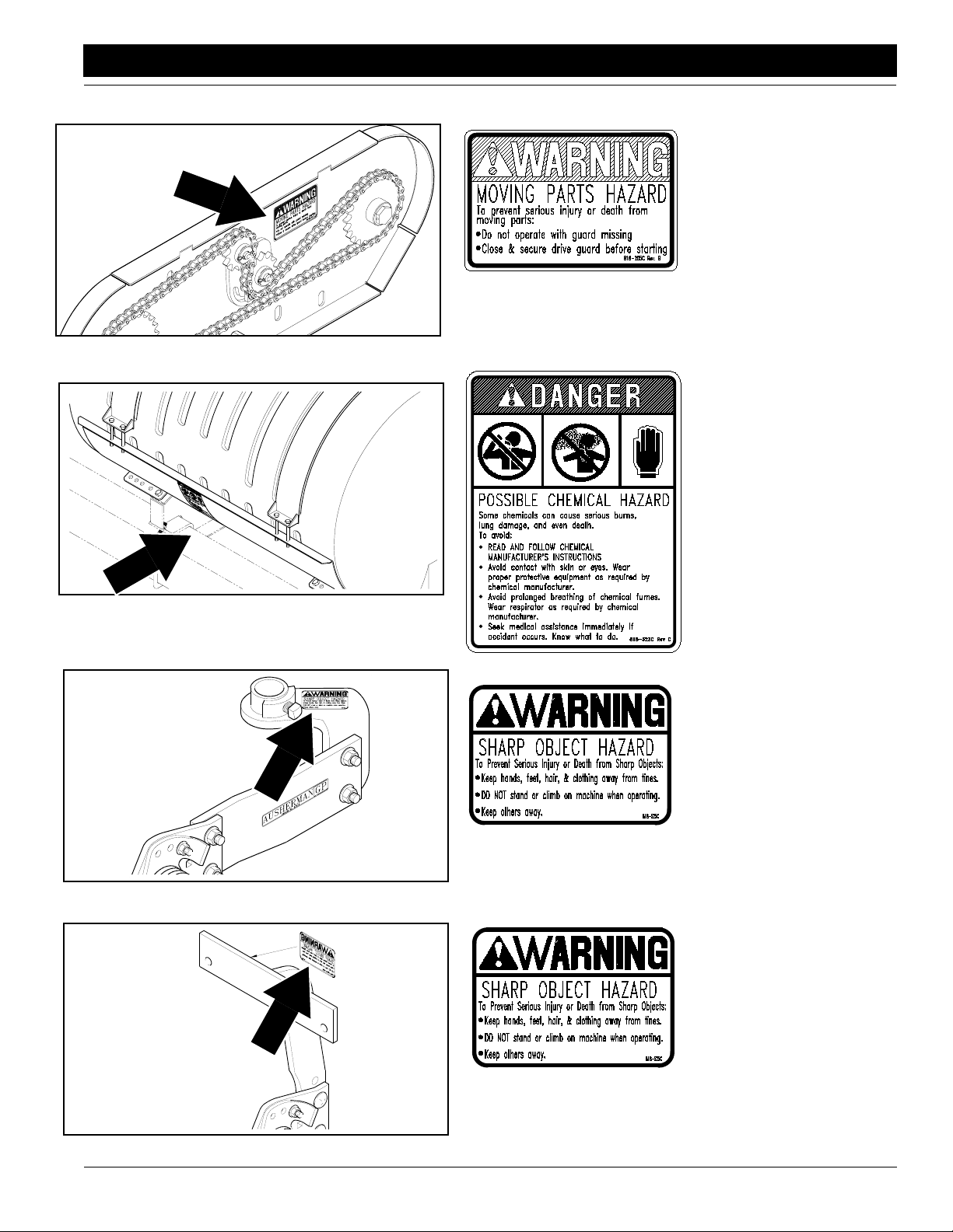
16864
818-205C
Moving Parts Warning
Liquid-Dry Fertilizer Option
15723
15732
818-323C
Chemical Hazard Warning
Liquid Fertilizer Option
818-525C
Sharp Object Warning
Terra-Tine
10/10/12
15733
818-525C
Sharp Object Warning
Terra-Tine
PT6030 and PT8030 Pull-Type Planter 401-032M-A
8
Page 11
Introduction
Introduction
Great Plains Mfg., Inc.
Great Plains welcomes you to its growing family of new
product owners. This implement has been designed with
care and built by skilled workers using quality materials.
Proper setup, maintenance and safe operating practices
will help you get years of satisfactory use from the ma
-
chine.
Description of Unit
The 6- and 8-row, pull-type planter is a towed seeding implement. The frame consists of 7-by-7-inch tubing. Planting rates are adjustable by changing sprockets on the
planter transmission or contact drive. Row units are
mounted on the frame. Seed hoppers are standard on the
row units; chemical hoppers and granular-chemical appli
cators are available. Springs on each row unit provide
down pressure needed for the double-disk openers to
make a seed trench. Finger-pickup meters singulate and
dispense seed from the hopper and deliver it to the trench.
Seeding depth is controlled by side gauge wheels on the
openers. Closing wheels or disks close the trench. With an
optional 5-by-7-inch fertilizer bar, the planter can be outfit
ted with dry or liquid fertilizer application and tillage attachments.
Intended Usage
Use this implement for seeding row crops in large fields.
Tow the implement behind an agricultural tractor at plant
ing speed of 5 mph and at transport speeds of less than 20
mph. The unit is designed for conventionally tilled fields
but can be used in no- or minimum-till conditions if outfit
ted with optional tillage attachments.
Using This Manual
This manual will familiarize you with safety, assembly, operation, adjustments, troubleshooting and maintenance.
Read this manual and follow the recommendations to help
ensure safe and efficient operation.
The information in this manual is current at printing. Some
parts may change to assure top performance.
Definitions
Right-hand and left-hand as used in this manual are determined by facing the direction the machine will travel while
in use unless otherwise stated.
IMPORTANT: A crucial point of information related to
the preceding topic. For safe and correct operation,
read and follow the directions provided before continuing.
NOTE: Useful information related to the preceding topic.
parts and equipment specially designed for Great Plains
products.
Your machine’s parts were specially designed and should
only be replaced with Great Plains parts. Always use the
serial and model number when ordering parts from your
Great Plains dealer. The serial-number plate is located on
the 7-by-7-inch, main frame tube on the left-hand side of
the planter as shown in Figure A.
-
-
Great Plains
MANUFACTURING INCORPORATED
ASSARIA, KANSAS 67416
MODEL NO.
PT 6030
SERIAL NO.
GP-U0000000
-
Record your planter model and serial number here for quick
Figure A
Serial Number
reference:
Model Number: _________________________________
Serial Number: _________________________________
Your Great Plains dealer wants you to be satisfied with
your new machine. If you do not understand any part of
this manual or are not satisfied with the service received,
please take the following actions.
1. Discuss the matter with your dealership service man-
ager. Make sure they are aware of any problems so
they can assist you.
2. If you are still not satisfied, seek out the owner or gen-
eral manager of the dealership.
3. For further assistance write to:
Product Support
Great Plains Mfg. Inc., Service Department
PO Box 5060
Salina, KS 67402-5060
14921
Owner Assistance
If you need customer service or repair parts, contact a
Great Plains dealer. They have trained personnel, repair
PT6030 and PT8030 Pull-Type Planter 401-032M-A 10/10/12
9
Page 12
Great Plains Mfg., Inc.
R
D
A
f
I
Section 1 Planter Preparation and Setup
Section 1 Planter Preparation and Setup
Initial Preparation of the Planter
• Perform all beginning of season and daily planter service as discussed in “Section 5 Maintenance and
Lubrication” on page 35.
• Lubricate the planter as indicated in the Lubrication
portion of
tion” on page 35.
• Check the chains for proper tension and alignment as
shown in
on page 35.
• Check all nuts, bolts and screws. Refer to the Torque
Value Chart,
• Check that all cotter pins are spread.
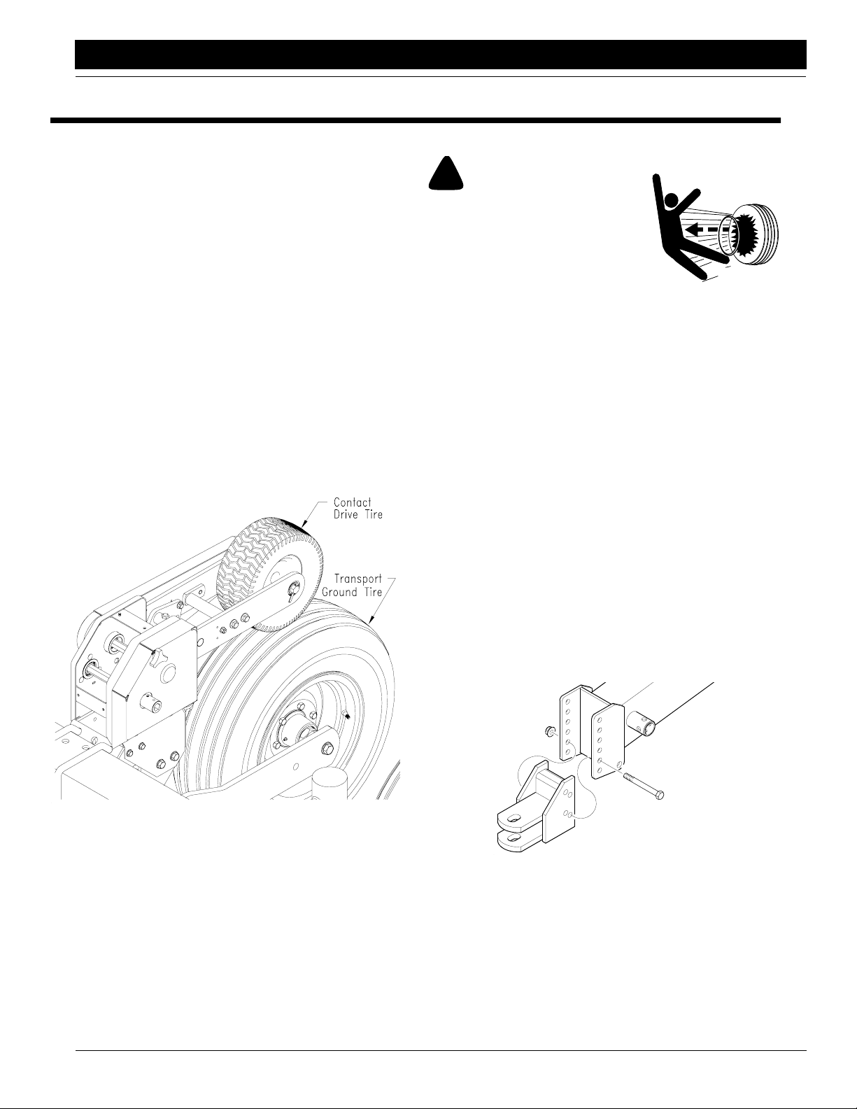
• Check the tires for proper inflation. Contact drive and
gauge wheel tires should be inflates as follows. Refer
Figure 1-1.
to
Transport/Ground Drive 9.5L X 15-8 ply. . . . . .44 psi
Contact Drive 13-6.50 X 6 . . . . . . . . . . . . . . . . 40 psi
“Section 5 Maintenance and Lubrica-
“Section 5 Maintenance and Lubrication”
“Appendix” on page 52.
!
DANGER!
im and tire servicing can be dangerous. Explosive separation of a tire and
rim parts can cause serious injury
or death.
o not attempt to mount a tire unless you have the proper equipment and
experience to perform the job. This should only be done by persons properly trained and equipped to do the job.
lways maintain the correct tire pressure. Do not inflate tires
above recommended pressure.
When inflating tires, use a clip-on air chuck and extension
hose long enough to allow you to stand to one side and not in
ront of or over tire assembly. Use a safety cage to enclose tire
and rim assembly when inflating.
nspect tires and wheels daily. Do not operate with low pressure, cuts, bubbles, damaged rims or missing lug bolts and
nuts.
Leveling the Planter
During initial setup and periodically throughout the planting season, check that the planting units are running level.
When planting, the top of the hopper support panel (1)
should be parallel to the ground as shown in
To level the planter, the bottom of the main frame tube
must run between 20 and 22 inches above ground when
lowered into planting position. See
To obtain the correct height, reposition the planter hitch on
the tongue. The hitch can be turned over for different
heights.
Contact Drive Transport/Ground Drive
Figure 1-1
15057
Figure 1-2
Hitch Height Adjustment
Figure 1-3.
Figure 1-3.
10/10/12
PT6030 and PT8030 Pull-Type Planter 401-032M-A
10
Page 13
Section 1 Planter Preparation and Setup
Great Plains Mfg., Inc.
Top of Hopper Support Level with Ground
Leveling the Planter
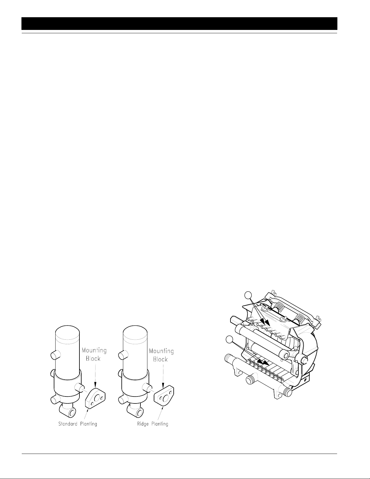
Ridge Planting
To prepare the planter for ridge planting, you must lower
the gauge wheels by inverting the cylinder mounting
blocks.
To invert, refer to Figure 1-4.
1. Block up the frame to remove weight from tires.
2. Remove the four 5/8-inch cap screws.
3. Invert mounting blocks and re-install cap screws.
Torque to specification as listed on the Torque Values
Chart,
“Appendix” on page 52.
Figure 1-3
Liquid Fertilizer Option
The pump should always be mounted even with or lower
than the fertilizer tank.
Hose arrangement is important for efficient pump operation. If you will be using fewer hoses than there are on the
pump, remove pump hoses from near the center of the in
take manifold (1) and cap the intake ports (2).
2
1
14956
-
Figure 1-5
Removing Squeeze Pump Hoses
Figure 1-4
Ridge Planting Adjustment
PT6030 and PT8030 Pull-Type Planter 401-032M-A 10/10/12
11
14958
12409
Page 14
Great Plains Mfg., Inc.
Section 2 Operation
Section 2 Operation
Basic Planting Operation
For the best planting results:
• plant at 5 mph,
• maintain tire pressure in the gauge tires and
• replace worn meter parts.
Rephasing the Hydraulic System
The hydraulic lift system on your Great Plains pull-type
planter is a master-and-slave system. All cylinders in the
system are two way. Each time the planter is lowered into
planting position, the system is rephased.
If unlevel lifting occurs, lower the planter to the ground and
hold the remote lever momentarily.
If following this procedure does not level planter lifting, refer to “Section 5 Maintenance and Lubrication” on
page 35.
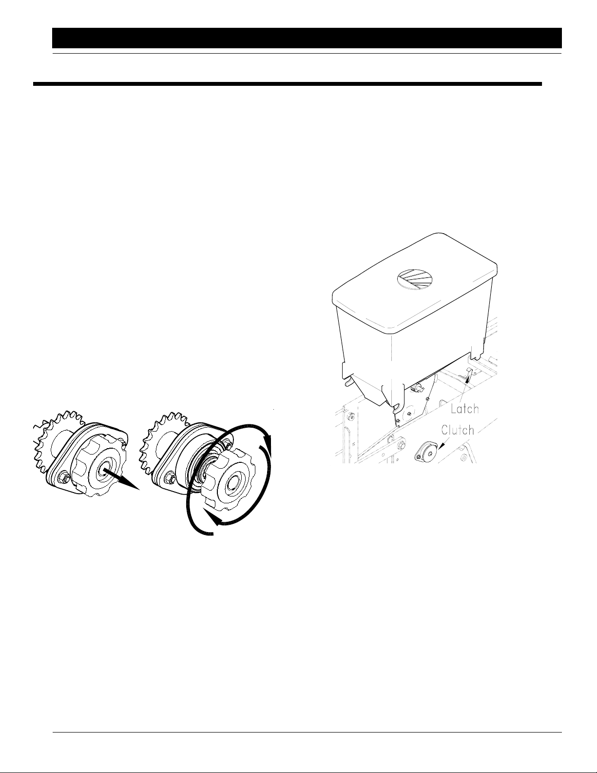
Seed Meter and Hopper Operation
This planter is equipped with a 12-finger mechanical corn
meter.
To disengage the seed-meter or chemical-hopper clutch,
pull the knob and rotate 90 degrees clockwise or counterclockwise until the roll pin aligns with the notch in the end
of the drive hub. Release knob. See
To engage, pull and rotate the knob until the shaft aligns
with the drive hub, then release.
Figure 2-1.
on top of the seeds in the hopper. The graphite will work its
way down to lubricate the meter mechanism.
For more information on the seed meter, see also Planting
Rates, “Adjustments,”
shooting” on page 32 and “Section 5 Maintenance and
Lubrication” on page 35.
The row unit is equipped with a 2-bushel seed hopper.
Before filling the seed hopper, clear it of foreign objects. To
remove the hopper, disengage the meter drive clutch and
the hopper latch. See
page 15, “Section 4 Trouble-
Figure 2-2.
16868
Figure 2-1
Disengage Meter Clutch
To extend the life and maximize efficiency of the finger
pickup meter, sprinkle 1 teaspoon of powdered graphite
10/10/12
Figure 2-2
Meter Clutch, Latch & Seed Hopper
After filling the hopper with clean seeds always replace the
hopper lid. Operating with the lids attached prevents ob
jects from entering the hopper and also aids in keeping out
moisture.
Empty the contents of the hopper periodically to avoid the
collection of dirt and other materials.
PT6030 and PT8030 Pull-Type Planter 401-032M-A
12343
-
12
Page 15
Section 2 Operation
Great Plains Mfg., Inc.
Chemical Meters and Hopper
The optional chemical hopper comes in two versions: one
chemical meter and an 80-pound-capacity hopper or two
chemical meters and a divider that separates the hopper
into two 40-pound compartments.
To engage or disengage the chemical meter, refer to the
instructions under Seed Meter and Hopper Operation,
page 12.
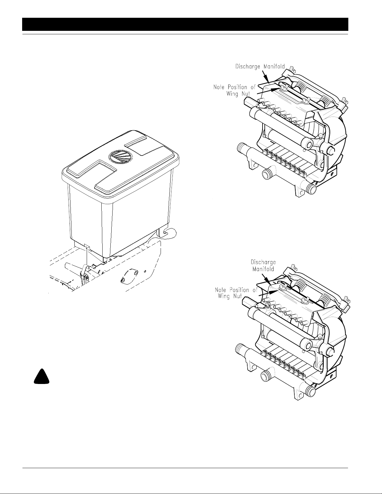
Before filling the chemical hoppers, clear them of foreign
objects. To remove the hoppers, disengage the meter
clutch and undo the over-center latch at the front of the
hopper.See
Figure 2-3
.
To position the manifold forward for operation, loosen the
wing nuts on the manifold and pull the manifold forward.
Secure wing nuts as shown in
Figure 2-4
Discharge Manifold Forward Position–In Use
Figure 2-4.
14949
16866
Figure 2-3
Chemical Hopper
After filling the hoppers, replace the hopper lids. Operating
with the lids attached prevents objects from entering the
hopper and also aids in keeping out moisture.
Empty the contents of the hoppers periodically to avoid the
collection of dirt and other materials.
Liquid Fertilizer Operation
!
WARNING!
Agricultural chemicals can be dangerous if not selected and
handled with care. Always read and follow directions supplied
by the chemical manufacturer.
For accurate metering, keep pump speed below 125 rpm.
To operate the pump, the discharge manifold must be in
the forward position as shown in
shipped in the rearward position.
Figure 2-4. Pumps are
When the pump is not in use, reposition the pump manifold
to prolong the life of the hoses in the squeeze pump. To re
position the discharge manifold to the rearward position,
loosen the wing nuts and push the manifold back as
shown in
For more information on preparing the squeeze pump for
parking and storage, refer to Squeeze Pumps, “Mainte
nance and Lubrication,” page 40 and the John Blue
manual provide with the pumps.
Figure 2-5.
14950
Figure 2-5
Discharge Manifold Rearward Position–
Parking and Storage
-
-
PT6030 and PT8030 Pull-Type Planter 401-032M-A 10/10/12
13
Page 16
Great Plains Mfg., Inc.
Section 2 Operation
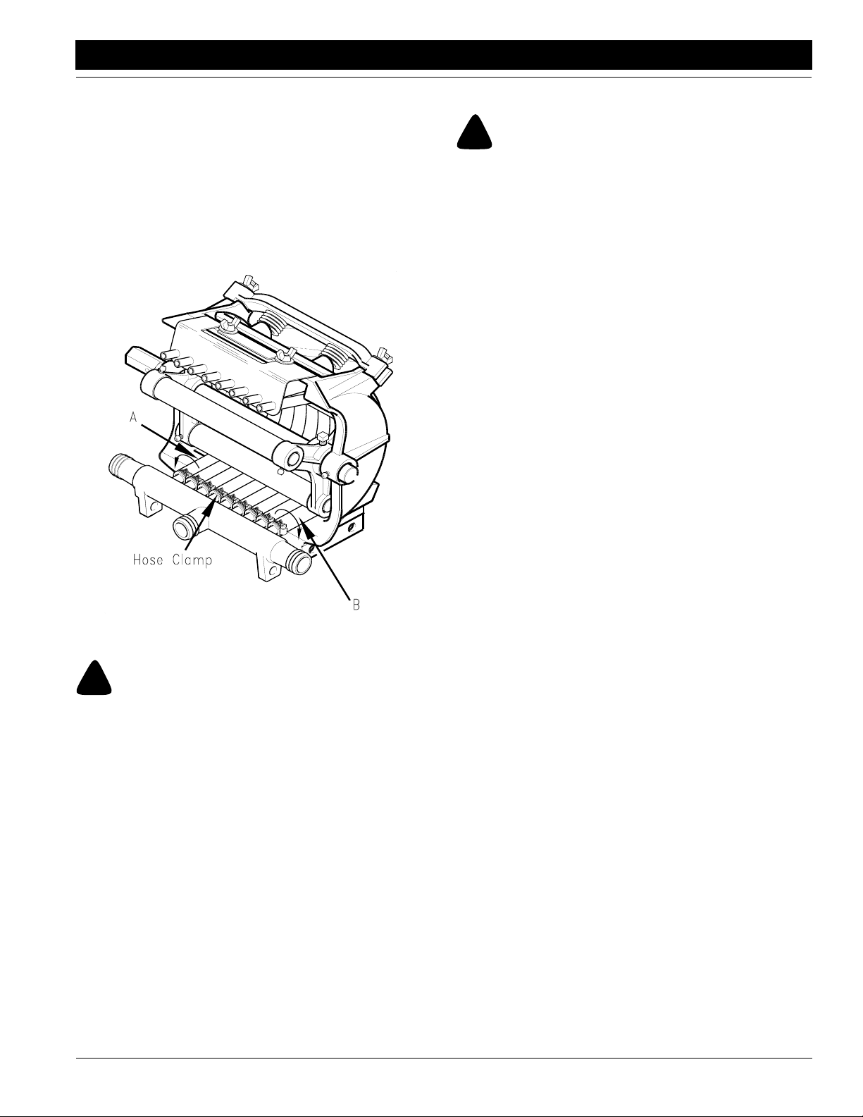
Squeeze Pump Hose Alignment
Refer to Figure 2-6.
If end hoses (A and B) should run off the back, re-align
hoses as follows:
1. On hose A, loosen hose clamps on intake manifold
and twist hose counter-clockwise 1/4 turn.
2. On hose B, loosen hose clamp on intake manifold and
twist hose clockwise 1/4 turn.
3. Retighten hose clamp.
Transporting
!
CAUTION!
Never transport the planter faster than 20 miles per hour!
Before transporting the planter, check and practice the following items:
• The planter can be transported with full hoppers of
seed. It is best NOT to because the extra weight in
creases the chances for problems on the road.
• Check that the gauge-wheel tires are properly inflated
as listed on the Tire Inflation Chart,
page 52.
• Comply with all federal, state and local safety laws
when traveling on public roads.
• Remember, the planter is wider than the tractor and
extreme care must be taken to allow for safe clear
ance.
• Make sure the safety chain is properly attached with
enough slack in the chain to permit turning.
• Always transport the marker with it folded in the flat
fold position.
“Appendix” on
-
-
Figure 2-6
Hose Alignment
!
CAUTION!
Avoid pressure when using the quick-fill attachment. The rubber
plugs installed in the manifold may be forced out under pressure.
12402
Marker Operation
Markers can be raised simultaneously but can only be lowered one at a time. If both markers are required down at
the same time, run one marker down, momentarily start to
raise it, reverse the hydraulic lever and lower the opposite
marker. Holding the lever down then will force both mark
ers down.
On a tractor where the oil flow cannot be controlled, the
rate of flow of oil from the tractor may be greater than the
rate at which the marker cylinder can accept it. The tractor
hydraulic control lever will have to be held until the cylinder
reaches the end of its stroke. This occurs most often on
tractors with an open-center hydraulic system.
On tractors with a closed-center hydraulic system, the
tractor’s hydraulic flow control can be set so the tractor’s
detent will function properly.
-
10/10/12
PT6030 and PT8030 Pull-Type Planter 401-032M-A
14
Page 17

Section 3 Adjustments
Section 3 Adjustments
Planting Rate
Transmission Adjustment
To change planting population, change the sprocket combination on the transmission.
1. Refer to “Planting Rates for Finger Pickup Corn
Meters” on page 16 or “Planting Rates for Brush
Meters” on page 17 for the proper sprocket combina-
tion for your desired planting population.
2. Remove the cover from the transmission by loosening
the knob on the cover.
16861
Figure 3-1
Planter Transmission
3. Loosen the carriage bolt and flange nut on the idler
plate. Rotate the idler plate to move the idlers out of
the chain.
4. Remove the chain. Remove sprockets currently on
transmission shafts.
5. Find the correct sprockets on the storage brackets
and place on the transmission shafts.
NOTE: When not in use, store all extra sprockets on the
storage bracket.
6. Place the sprockets on the drive/driven shafts.
7. Re-route chain over idlers and sprockets.
8. Turn the idler plate counter-clockwise to take up chain
slack. Chain should have a maximum of 1/4-inch
slack.
9. Retighten the carriage bolt and flange nut to secure
idler plate.
10. Replace the transmission cover and hand tighten the
knob.
2-to-1 Drive Reduction
The 15/28 tooth drive sprocket located on the inner side of
the contact drive wheel assembly will give you a 2-to-1
drive reduction and reduce planting rates by about onehalf.
NOTE: After each sprocket combination adjustment, make
a field check to be sure you are planting at the desired
rate.
Great Plains Mfg., Inc.
16863
Figure 3-2
2-to-1 Drive Reduction
Checking Planting Population
After setting the transmission or contact-drive reduction,
always field check the planting population as follows.
1. Release spring pressure on opener disks and wheels.
2. Tie up closing disks and wheels to hopper support using a chain or heavy wire. Pin up optional Seed-Lok
wheels
3. Adjust the planting depth to a shallow setting.
4. Plant at a normal speed for a short distance.
5. For 30-inch rows, measure 17 feet 6 inches (one-thousandth of an acre.)
6. Count the number of seeds in one row over the measured distance.
7. Multiply the number of seeds counted by 1000. This
gives you total population.
Example
• 30-inch row spacing
• Measure 17 feet 6 inches
• 24 seeds over measured distance in one row
24 X1000 = 24,000 plant population per acre
If the planting population is significantly different than desired, make the following checks.
• Double check the sprocket combination in the transmission. Refer to the “Planting Rates for Finger
Pickup Corn Meters” on page 16.
• Check air pressure in the gauge-wheel tires. Refer to
Tire Inflation Chart,
• Check for meter malfunction or excessive contactdrive-wheel slippage. Refer to
shooting” on page 32.
“Appendix” on page 52.
“Section 4 Trouble-
PT6030 and PT8030 Pull-Type Planter 401-032M-A 10/10/12
15
Page 18

Great Plains Mfg., Inc.
Section 3 Adjustments
Planting Rates for Finger Pickup Corn Meters
Drive
Driven
Figure 3-1
Planter Transmission Driver and Driven Sprockets
Planting Rates 30" Row Width
Planting
Population/
Acre
16,074 17 28 4 to 8 13.0
16,668 17 27 4 to 8 12.5
17,313 17 26 4 to 8 12.1
17,971 19 28 4 to 8 11.6
13,228 17 25 4 to 8 15.8
16,674 19 27 4 to 8 12.5
18,739 17 24 4 to 8 11.2
19,323 19 26 4 to 8 10.8
19,550 17 23 4 to 8 10.7
20,093 19 25 4 to 8 10.4
20,922 19 24 4 to 8 10.0
21,692 23 28 4 to 8 9.6
21,828 19 23 4 to 8 9.6
22,493 23 27 4 to 8 9.3
22,632 24 28 4 to 8 9.2
23,355 23 26 4 to 8 9.0
23,467 24 27 4 to 8 8.9
23,565 25 28 4 to 8 8.9
Transmission
Sprockets
Drive Driven
Recom-
mended Speed
Range (mph)
Average Seed
16861
Spacing
(inches)
Planting Rates 30" Row Width
Planting
Population/
Acre
23,630 17 19 4 to 7.5 8.8
24,286 23 25 4 to 7.5 8.6
24,367 24 26 4 to 7.5 8.6
24,435 25 27 4 to 7.5 8.6
24,504 26 28 4 to 7.5 8.5
25,288 23 24 4 to 7.5 8.3
25,338 24 25 4 to 7.5 8.3
25,372 25 26 4 to 7.5 8.2
25,409 26 27 4 to 7.5 8.2
25,444 27 28 4 to 7.5 8.2
26,383 23 23 4 to 7 7.9
27,357 28 27 4 to 7 7.6
27,394 27 26 4 to 7 7.6
27,471 25 24 4 to 7 7.6
27,525 24 23 4 to 7 7.6
28,406 28 26 4 to 6.5 7.4
28,486 27 25 4 to 6.5 7.3
28,661 25 23 4 to 6.5 7.3
29,457 19 17 4 to 6.5 7.1
29,538 28 25 4 to 6.5 7.1
29,661 27 24 4 to 6.5 7.0
29,803 26 23 4 to 6.5 7.0
30,756 28 24 3 to 6 6.8
30,945 27 23 3 to 6 6.8
31,889 23 19 3 to 5.5 6.6
32,088 28 23 3 to 5.5 6.5
33,270 24 19 3 to 5.5 6.3
34,642 25 19 3 to 5 6.0
35,604 23 17 3 to 5 5.9
36,023 26 19 3 to 5 5.8
37,146 24 17 3 to 5 5.6
37,403 27 19 3 to 5 5.6
38,678 25 17 3 to 4.5 5.4
38,784 28 19 3 to 4.5 5.4
40,219 26 17 3 to 4.5 5.2
41,761 27 17 3 to 4.5 5.0
43,303 28 17 3 to 4.5 4.8
Transmission
Sprockets
Drive Driven
Recom-
mended Speed
Range (mph)
Average Seed
Spacing
(inches)
10/10/12
PT6030 and PT8030 Pull-Type Planter 401-032M-A
16
Page 19

Great Plains Mfg., Inc.
Section 3 Adjustments
Planting Rates for Brush Meters
Planting Rates 30" Row Width
60 Cell
Soybean or
High Rate Milo/
Speed
Sprockets
Transmission
Drive Driven
17 28 2 to 8 80,928 2.6 64,742 3.2 48,557 4.3 40,464 5.2
17 27 2 to 8 83,926 2.5 67,141 3.1 50,356 4.2 41,963 5.0
17 26 2 to 8 87,154 2.4 69,723 3.0 52,292 4.0 43,577 4.8
19 28 2 to 8 90,449 2.3 72,359 2.9 54,269 3.9 45,225 4.6
19 27 2 to 8 93,799 2.2 75,039 2.8 56,279 3.7 46,900 4.5
17 24 2 to 8 94,416 2.2 75,533 2.8 56,650 3.7 47,208 4.4
17 23 2 to 8 98,521 2.1 78,817 2.7 59,113 3.5 49,261 4.2
19 25 2 to 8 101,303 2.1 81,042 2.6 60,782 3.4 50,652 4.1
19 24 2 to 8 105,524 2.0 84,419 2.5 63,314 3.3 52,762 4.0
23 28 2 to 8 109,491 1.9 87,593 2.4 65,695 3.2 54,746 3.8
19 23 2 to 8 110,112 1.9 88,090 2.4 66,067 3.2 55,056 3.8
24 28 2 to 8 114,252 1.8 91,402 2.3 68,551 3.0 57,126 3.7
24 27 2 to 8 118,483 1.8 94,786 2.2 71,090 2.9 59,242 3.5
17 19 2 to 8 119,263 1.8 95,410 2.2 71,558 2.9 59,631 3.5
24 26 2 to 8 123,040 1.7 98,432 2.1 73,824 2.8 61,520 3.4
26 28 2 to 8 123,773 1.7 99,018 2.1 74,264 2.8 61,886 3.4
24 25 2 to 8 127,962 1.6 102,370 2.0 76,772 2.7 63,981 3.3
26 27 2 to 8 128,357 1.6 102,686 2.0 77,014 2.7 64,178 3.3
23 23 2 to 8 133,294 1.6 106,635 2.0 79,976 2.6 66,647 3.1
27 26 2 to 8 138,420 1.5 110,736 1.9 83,052 2.5 69,210 3.0
24 23 2 to 8 139,089 1.5 111,271 1.9 83,453 2.5 69,544 3.0
25 23 2 to 8 144,884 1.4 115,907 1.8 86,930 2.4 72,442 2.9
19 17 2 to 8 148,975 1.4 119,180 1.8 89,385 2.3 74,488 2.8
27 24 2 to 8 149,955 1.4 119,964 1.7 89,973 2.3 74,978 2.8
28 24 2 to 8 155,509 1.3 124,407 1.7 93,305 2.2 77,755 2.7
23 19 2 to 8 161,355 1.3 129,084 1.6 96,813 2.2 80,678 2.6
28 23 2 to 8 162,270 1.3 129,816 1.6 97,362 2.1 81,135 2.6
24 19 2 to 8 168,371 1.2 134,696 1.6 101,023 2.1 84,185 2.5
25 19 2 to 8 175,386 1.2 140,309 1.5 105,232 2.0 87,693 2.4
23 17 2 to 8 180,338 1.2 144,270 1.5 108,233 1.9 90,169 2.3
26 19 2 to 7 182,402 1.1 145,922 1.4 109,441 1.9 91,201 2.3
27 19 2 to 7 189,417 1.1 151,534 1.4 113,650 1.8 94,709 2.2
28 19 2 to 7 196,433 1.1 157,146 1.3 117,860 1.8 98,216 2.1
26 17 2 to 7 203,861 1.0 163,089 1.3 122,317 1.7 101,930 2.1
27 17 2 to 7 211,702 0.9 169,362 1.2 127,021 1.6 105,851 2.0
28 17 2 to 7 219,542 0.9 175,634 1.2 131,725 1.6 109,771 1.9
Range
(mph)
Grain Sorghum
Planting
Population/
Acre
Average Seed
Spacing
(inches)
Planting
Population/
48 Cell
Specialty Soybean or
High Rate
Acid-delinted Cotton
Average Seed
Acre
Spacing
(inches)
Acid-delinted
Large Cotton
Planting
Population/
Acre
36 Cell
Average Seed
Spacing
(inches)
Milo/Grain Sorghum or
Acid-delinted Cotton
Planting
Population/
Acre
30 Cell
Average Seed
Spacing
(inches)
NOTE: See Planting Rate on page 15 for additional information. Always check seed population in the field to ensure
planting rates are correct.
PT6030 and PT8030 Pull-Type Planter 401-032M-A 10/10/12
17
Page 20

Great Plains Mfg., Inc.
Section 3 Adjustments
Planting Rates for Brush Meters (continued)
Meters equipped with the 12 cell acid-delinted hill-drop
cotton discs will plant from 3 to 6 seeds per cell because of
variations in cotton seed size.
Determine which hill spacing is desired and select the
transmission ratio that is closest to that hill spacing on the
chart.
To determine the average seeds per hill and hills per acre
do the following field check:
Planting Rates 30" Row Width
Transmission
Sprockets
Drive Driven
17 28 2 to 8 16,186 12.9
17 27 2 to 8 16,785 12.5
17 26 2 to 8 17,431 12.0
19 28 2 to 8 18,090 11.6
19 27 2 to 8 18,760 11.1
17 24 2 to 8 18,883 11.1
17 23 2 to 8 19,704 10.6
19 25 2 to 8 20,261 10.3
19 24 2 to 8 21,105 9.9
23 28 2 to 8 21,898 9.5
19 23 2 to 8 22,022 9.5
24 28 2 to 8 22,850 9.2
24 27 2 to 8 23,697 8.8
17 19 2 to 8 23,853 8.8
24 26 2 to 8 24,608 8.5
26 28 2 to 8 24,755 8.4
24 25 2 to 8 25,592 8.2
26 27 2 to 8 25,671 8.1
23 23 2 to 8 26,659 7.8
Speed
Range
(mph)
Hill-drop Cotton, Acid-delinted
Hills/Acre
12 Cell
Average Hill
Spacing
(inches)
1. Measure 1/1000 of an acre. (1/1000 acre = length of
row 17’5” for 30” widths).
2. Multiply the average seed per hill by hills per acre.
Example:
4 seeds per hill x (13 hills x 1000) = 52,000
Planting Rates 30" Row Width
Transmission
Sprockets
Drive Driven
27 26 2 to 8 27,684 7.6
24 23 2 to 8 27,818 7.5
25 23 2 to 8 28,977 7.2
19 17 2 to 8 29,795 7.0
27 24 2 to 8 29,991 7.0
28 24 2 to 8 31,102 6.7
23 19 2 to 8 32,271 6.5
28 23 2 to 8 32,454 6.5
24 19 2 to 8 33,674 6.2
25 19 2 to 8 35,077 6.0
23 17 2 to 8 36,068 5.8
26 19 2 to 7 36,480 5.7
27 19 2 to 7 37,883 5.5
28 19 2 to 7 39,287 5.3
26 17 2 to 7 40,772 5.1
27 17 2 to 7 42,340 4.9
28 17 2 to 7 43,908 4.8
Speed
Range
(mph)
Hill-drop Cotton, Acid-delinted
Hills/Acre
12 Cell
Average Hill
Spacing
(inches)
NOTE: See Planting Rate on page 15 for additional information. Always check seed population in the field to ensure
planting rates are correct.
10/10/12
PT6030 and PT8030 Pull-Type Planter 401-032M-A
18
Page 21

Section 3 Adjustments
Granular Chemical Rates
The application rate is determined by:
• the size of the opening on the meter and
• travel speed.
The size of the opening is adjustable, but ground speed
has the greatest impact on the application rate. For exam
ple, if speed is reduced from 6 to 3 mph, chemical concentration will nearly double.
Application rates will also vary with the consistency and
composition of the chemicals, air temperature, humidity
and ground speed. Because of the wide variability in ap
plication rates, you must field check the actual rate of application for each meter.
!
WARNING!
Agricultural chemicals can be dangerous if not selected and
handled with care. Always read and follow directions supplied
by the chemical manufacturer.
-
Great Plains Mfg., Inc.
-
Figure 3-3
Hopper Knob
14947
To adjust the chemical rate:
1. Select a meter setting as a starting point.
• If the chemical manufacturer recommends ounces per
1000 linear row feet or pounds-per-acre for a given
band width and row spacing, use the recommended
meter setting as a starting point.
• If the chemical manufacturer recommends pounds
per acre for complete (broadcast) coverage, you must
calculate the pounds per acre for your band width and
row area. Refer to Conversion from Broadcast to Row
Coverage,
• If the meter setting is not available from the chemical
manufacturer, use
Charts” on page 21. The charts are approximate and
are based on a ground speed of 5 mph. Use these
charts as a starting point for setting the meter.
2. Turn meter knob until the display shows the correct
number. See
3. Fill the hoppers with chemical.
4. Attach a plastic bag to each chemical
diffuser.
5. Drive 500 feet at a normal planting speed.
6. Weigh the contents of the bag in ounces.
7. Multiply weight by 2.2 to determine the pounds
per acre.
8. If necessary, adjust the meter setting and repeat
steps.
page 19.
“Granular Chemical Rate
Figure 3-3.
IMPORTANT: If a significant difference in rate is observed between rows, the meter may require recalibration. Refer to Recalibrating Chemical Meter, page
20.
Conversion from Broadcast to Row Coverage
If the chemical manufacturer recommends pounds per
acre for complete (broadcast) coverage, you must reduce
the pounds per acre rate to match for your band width and
row area. Use the following formula to find the pounds per
acre for your band width and row spacing.
A X B/C = Pounds per Acre Application Rate
Where:
A = Recommended rate in pounds per acre for complete
(broadcast) coverage
B = Band width in inches
C = Row spacing in inches
NOTE: Measure the actual band width applied in your conditions and use this width in your calculations.
Example: The chemical manufacturer recommends
20 pounds per acre for complete broadcast coverage.
The band width is 14 inches. The row spacing is 30
inches.
20 x 14/30 = 9.3 pounds per acre
Set meter to setting recommended for 9.3 pounds per
acre.
PT6030 and PT8030 Pull-Type Planter 401-032M-A 10/10/12
19
Page 22

Great Plains Mfg., Inc.
Section 3 Adjustments
Recalibrating Granular Chemical Meters
If it should ever become necessary to recalibrate the granular meter on the chemical hopper, proceed as follows.
1. Remove and empty hopper. Turn hopper upside
down.
2. Turn hopper knob shown in Figure 3-3 to 10.
3. See Figure 3-4. Loosen screws (1) in metering gate.
4. Insert calibration tool (2).
5. Re-adjust dial to 04.
6. Slide gate (3) to tool.
7. Retighten screws. Re-install hoppers, refill and check
per previous instructions.
15051
10/10/12
Figure 3-4
Recalibrating Meter
PT6030 and PT8030 Pull-Type Planter 401-032M-A
20
Page 23

Section 3 Adjustments
Granular Chemical Rate Charts
Clay Granules, Herbicide
Great Plains Mfg., Inc.
14914
Clay Granules Herbicide Rate Chart
Approximate Rate in Lbs/Acre
30 Inch Rows Ounces per 1000 Row Ft.
Meter
Setting
10 0.9 0.6 0.5 0.87 0.58 0.43
11 1.1 0.7 0.6 1.03 0.69 0.51
12 1.3 0.9 0.7 1.22 0.82 0.61
13 1.6 1.1 0.8 1.45 0.97 0.72
14 1.9 1.2 0.9 1.70 1.13 0.85
15 2.1 1.4 1.1 1.97 1.32 0.99
16 2.5 1.6 1.2 2.27 1.51 1.14
17 2.8 1.9 1.4 2.59 1.72 1.29
18 3.2 2.1 1.6 2.92 1.94 1.46
19 3.6 2.4 1.8 3.26 2.17 1.63
20 3.9 2.6 2.0 3.62 2.41 1.81
21 4.3 2.9 2.2 3.99 2.66 1.99
22 4.8 3.2 2.4 4.37 2.91 2.18
23 5.2 3.4 2.6 4.75 3.17 2.37
24 5.6 3.7 2.8 5.14 3.43 2.57
25 6.0 4.0 3.0 5.53 3.69 2.77
26 6.5 4.3 3.2 5.93 3.95 2.96
27 6.9 4.6 3.4 6.33 4.22 3.16
28 7.3 4.9 3.7 6.72 4.48 3.36
29 7.8 5.2 3.9 7.12 4.75 3.56
30 8.2 5.5 4.1 7.52 5.01 3.76
31 8.6 5.7 4.3 7.92 5.28 3.96
32 9.1 6.0 4.5 8.31 5.54 4.16
33 9.5 6.3 4.7 8.71 5.80 4.35
34 9.9 6.6 5.0 9.10 6.06 4.55
35 10.3 6.9 5.2 9.48 6.32 4.74
36 10.7 7.2 5.4 9.87 6.58 4.93
37 11.2 7.4 5.6 10.25 6.83 5.12
38 11.6 7.7 5.8 10.62 7.08 5.31
39 12.0 8.0 6.0 11.00 7.33 5.50
40 12.4 8.3 6.2 11.37 7.58 5.69
41 12.8 8.5 6.4 11.74 7.83 5.87
42 13.2 8.8 6.6 12.11 8.07 6.05
43 13.6 9.1 6.8 12.47 8.32 6.24
44 14.0 9.3 7.0 12.84 8.56 6.42
45 14.4 9.6 7.2 13.20 8.80 6.60
46 14.8 9.8 7.4 13.56 9.04 6.78
47 15.2 10.1 7.6 13.92 9.28 6.96
48 15.6 10.4 7.8 14.28 9.52 7.14
49 16.0 10.6 8.0 14.65 9.76 7.32
50 16.3 10.9 8.2 15.01 10.01 7.51
miles per hour miles per hour
4 6 8468
Clay Granules Herbicide Rate Chart (cont.)
Approximate Rate in Lbs/Acre
30 Inch Rows Ounces per 1000 Row Ft.
Meter
Setting
51 16.7 11.2 8.4 15.38 10.25 7.69
52 17.2 11.4 8.6 15.75 10.50 7.87
53 17.6 11.7 8.8 16.12 10.75 8.06
54 18.0 12.0 9.0 16.50 11.00 8.25
55 18.4 12.3 9.2 16.88 11.26 8.44
56 18.8 12.5 9.4 17.27 11.52 8.64
57 19.2 12.8 9.6 17.67 11.78 8.83
58 19.7 13.1 9.8 18.07 12.05 9.04
59 20.1 13.4 10.1 18.48 12.32 9.24
60 20.6 13.7 10.3 18.90 12.60 9.45
61 21.1 14.0 10.5 19.33 12.89 9.67
62 21.5 14.4 10.8 19.77 13.18 9.89
63 22.0 14.7 11.0 20.22 13.48 10.11
64 22.5 15.0 11.3 20.68 13.79 10.34
65 23.0 15.4 11.5 21.16 14.10 10.58
66 23.6 15.7 11.8 21.64 14.43 10.82
67 24.1 16.1 12.1 22.14 14.76 11.07
68 24.7 16.4 12.3 22.65 15.10 11.33
69 25.2 16.8 12.6 23.18 15.45 11.59
70 25.8 17.2 12.9 23.72 15.81 11.86
71 26.4 17.6 13.2 24.27 16.18 12.13
72 27.0 18.0 13.5 24.84 16.56 12.42
73 27.7 18.5 13.8 25.42 16.95 12.71
74 28.3 18.9 14.2 26.02 17.34 13.01
75 29.0 19.3 14.5 26.63 17.75 13.31
76 29.7 19.8 14.8 27.25 18.17 13.63
77 30.4 20.3 15.2 27.90 18.60 13.95
78 31.1 20.7 15.5 28.55 19.03 14.28
79 31.8 21.2 15.9 29.22 19.48 14.61
80 32.6 21.7 16.3 29.90 19.94 14.95
81 33.3 22.2 16.7 30.60 20.40 15.30
82 34.1 22.7 17.0 31.31 20.87 15.65
83 34.9 23.3 17.4 32.03 21.35 16.01
84 35.7 23.8 17.8 32.76 21.84 16.38
85 36.5 24.3 18.2 33.50 22.33 16.75
86 37.3 24.9 18.6 34.25 22.83 17.12
87 38.1 25.4 19.1 35.00 23.33 17.50
88 38.9 26.0 19.5 35.76 23.84 17.88
89 39.8 26.5 19.9 36.53 24.35 18.27
90 40.6 27.1 20.3 37.30 24.87 18.65
miles per hour miles per hour
4 6 8468
PT6030 and PT8030 Pull-Type Planter 401-032M-A 10/10/12
21
Page 24

Great Plains Mfg., Inc.
Section 3 Adjustments
Granular Chemical Rate Charts
Clay Granules, Insecticide
14914
Clay Granules Insecticide Rate Chart
Approximate Rate in Lbs/Acre
30 Inch Rows Ounces per 1000 Row Ft.
Meter
Setting
10 0.9 0.6 0.5 0.85 0.57 0.42
11 1.0 0.7 0.5 0.92 0.61 0.46
12 1.2 0.8 0.6 1.06 0.71 0.53
13 1.4 0.9 0.7 1.25 0.84 0.63
14 1.6 1.1 0.8 1.50 1.00 0.75
15 2.0 1.3 1.0 1.79 1.19 0.90
16 2.3 1.5 1.2 2.12 1.42 1.06
17 2.7 1.8 1.4 2.49 1.66 1.24
18 3.1 2.1 1.6 2.88 1.92 1.44
19 3.6 2.4 1.8 3.31 2.20 1.65
20 4.1 2.7 2.0 3.75 2.50 1.87
21 4.6 3.1 2.3 4.20 2.80 2.10
22 5.1 3.4 2.5 4.68 3.12 2.34
23 5.6 3.7 2.8 5.16 3.44 2.58
24 6.1 4.1 3.1 5.64 3.76 2.82
25 6.7 4.5 3.3 6.14 4.09 3.07
26 7.2 4.8 3.6 6.63 4.42 3.31
27 7.8 5.2 3.9 7.12 4.75 3.56
28 8.3 5.5 4.1 7.61 5.07 3.81
29 8.8 5.9 4.4 8.10 5.40 4.05
30 9.3 6.2 4.7 8.58 5.72 4.29
31 9.9 6.6 4.9 9.05 6.03 4.52
32 10.4 6.9 5.2 9.51 6.34 4.76
33 10.9 7.2 5.4 9.97 6.65 4.98
34 11.3 7.6 5.7 10.41 6.94 5.21
35 11.8 7.9 5.9 10.85 7.23 5.42
36 12.3 8.2 6.1 11.27 7.52 5.64
37 12.7 8.5 6.4 11.69 7.79 5.84
38 13.2 8.8 6.6 12.09 8.06 6.05
39 13.6 9.1 6.8 12.48 8.32 6.24
40 14.0 9.3 7.0 12.87 8.58 6.43
41 14.4 9.6 7.2 13.24 8.83 6.62
42 14.8 9.9 7.4 13.60 9.07 6.80
43 15.2 10.1 7.6 13.96 9.31 6.98
44 15.6 10.4 7.8 14.31 9.54 7.15
45 16.0 10.6 8.0 14.65 9.77 7.33
46 16.3 10.9 8.2 14.99 9.99 7.49
47 16.7 11.1 8.3 15.32 10.21 7.66
48 17.0 11.4 8.5 15.65 10.43 7.82
49 17.4 11.6 8.7 15.98 10.65 7.99
50 17.8 11.8 8.9 16.30 10.87 8.15
miles per hour miles per hour
4 6 8468
Clay Granules Insecticide Rate Chart (cont.)
Approximate Rate in Lbs/Acre
30 Inch Rows Ounces per 1000 Row Ft.
Meter
Setting
51 18.1 12.1 9.1 16.63 11.08 8.31
52 18.5 12.3 9.2 16.95 11.30 8.48
53 18.8 12.5 9.4 17.29 11.52 8.64
54 19.2 12.8 9.6 17.62 11.75 8.81
55 19.6 13.0 9.8 17.96 11.97 8.98
56 19.9 13.3 10.0 18.31 12.21 9.15
57 20.3 13.5 10.2 18.66 12.44 9.33
58 20.7 13.8 10.4 19.03 12.69 9.51
59 21.1 14.1 10.6 19.40 12.94 9.70
60 21.6 14.4 10.8 19.79 13.19 9.90
61 22.0 14.7 11.0 20.19 13.46 10.10
62 22.4 15.0 11.2 20.61 13.74 10.30
63 22.9 15.3 11.5 21.04 14.02 10.52
64 23.4 15.6 11.7 21.48 14.32 10.74
65 23.9 15.9 11.9 21.94 14.63 10.97
66 24.4 16.3 12.2 22.42 14.95 11.21
67 25.0 16.6 12.5 22.92 15.28 11.46
68 25.5 17.0 12.8 23.44 15.62 11.72
69 26.1 17.4 13.1 23.97 15.98 11.99
70 26.7 17.8 13.4 24.52 16.35 12.26
71 27.3 18.2 13.7 25.10 16.73 12.55
72 28.0 18.7 14.0 25.69 17.13 12.84
73 28.6 19.1 14.3 26.30 17.53 13.15
74 29.3 19.6 14.7 26.93 17.95 13.46
75 30.0 20.0 15.0 27.58 18.38 13.79
76 30.8 20.5 15.4 28.24 18.83 14.12
77 31.5 21.0 15.7 28.92 19.28 14.46
78 32.2 21.5 16.1 29.61 19.74 14.81
79 33.0 22.0 16.5 30.32 20.21 15.16
80 33.8 22.5 16.9 31.03 20.69 15.52
81 34.6 23.1 17.3 31.76 21.17 15.88
82 35.4 23.6 17.7 32.49 21.66 16.25
83 36.2 24.1 18.1 33.23 22.15 16.62
84 37.0 24.7 18.5 33.97 22.65 16.99
85 37.8 25.2 18.9 34.71 23.14 17.35
86 38.6 25.7 19.3 35.44 23.63 17.72
87 39.4 26.3 19.7 36.17 24.11 18.08
88 40.2 26.8 20.1 36.88 24.59 18.44
89 40.9 27.3 20.5 37.58 25.05 18.79
90 41.7 27.8 20.8 38.25 25.50 19.13
miles per hour miles per hour
4 6 8468
10/10/12
PT6030 and PT8030 Pull-Type Planter 401-032M-A
22
Page 25

Section 3 Adjustments
Granular Chemical Rate Charts
Sand Granules, Herbicide and Insecticide
Great Plains Mfg., Inc.
14914
Sand Granules Chemical Rate Chart
Approximate Rate in Lbs/Acre
30 Inch Rows Ounces per 1000 Row Ft.
Meter
Setting
5 1.7 1.1 0.8 1.53 1.02 0.76
6 2.2 1.4 1.1 1.98 1.32 0.99
7 2.7 1.8 1.3 2.47 1.65 1.23
8 3.3 2.2 1.6 3.00 2.00 1.50
9 3.9 2.6 1.9 3.56 2.38 1.78
10 4.5 3.0 2.3 4.17 2.78 2.08
11 5.2 3.5 2.6 4.82 3.21 2.41
12 6.0 4.0 3.0 5.50 3.67 2.75
13 6.8 4.5 3.4 6.23 4.15 3.12
14 7.6 5.1 3.8 7.00 4.66 3.50
15 8.5 5.7 4.2 7.80 5.20 3.90
16 9.4 6.3 4.7 8.65 5.77 4.32
17 10.4 6.9 5.2 9.53 6.35 4.77
18 11.4 7.6 5.7 10.45 6.97 5.23
19 12.4 8.3 6.2 11.41 7.60 5.70
20 13.5 9.0 6.7 12.39 8.26 6.20
21 14.6 9.7 7.3 13.41 8.94 6.71
22 15.8 10.5 7.9 14.47 9.64 7.23
23 16.9 11.3 8.5 15.55 10.36 7.77
24 18.1 12.1 9.1 16.65 11.10 8.33
25 19.4 12.9 9.7 17.78 11.86 8.89
26 20.6 13.7 10.3 18.94 12.62 9.47
27 21.9 14.6 11.0 20.11 13.41 10.06
28 23.2 15.5 11.6 21.30 14.20 10.65
29 24.5 16.3 12.3 22.51 15.01 11.26
30 25.8 17.2 12.9 23.73 15.82 11.87
31 27.2 18.1 13.6 24.97 16.64 12.48
32 28.5 19.0 14.3 26.21 17.47 13.10
33 29.9 19.9 14.9 27.45 18.30 13.73
34 31.3 20.8 15.6 28.71 19.14 14.35
35 32.6 21.8 16.3 29.96 19.97 14.98
36 34.0 22.7 17.0 31.21 20.81 15.61
37 35.4 23.6 17.7 32.46 21.64 16.23
38 36.7 24.5 18.4 33.71 22.47 16.85
39 38.1 25.4 19.0 34.95 23.30 17.47
40 39.4 26.3 19.7 36.17 24.12 18.09
41 40.7 27.1 20.4 37.39 24.93 18.70
42 42.0 28.0 21.0 38.60 25.73 19.30
43 43.3 28.9 21.7 39.79 26.53 19.90
44 44.6 29.7 22.3 40.97 27.31 20.48
45 45.9 30.6 22.9 42.13 28.08 21.06
miles per hour miles per hour
4 6 8468
Sand Granules Chemical Rate Chart (cont.)
Approximate Rate in Lbs/Acre
30 Inch Rows Ounces per 1000 Row Ft.
Meter
Setting
46 47.1 31.4 23.6 43.27 28.85 21.63
47 48.3 32.2 24.2 44.39 29.59 22.20
48 49.5 33.0 24.8 45.49 30.33 22.75
49 50.7 33.8 25.4 46.58 31.05 23.29
50 51.9 34.6 25.9 47.64 31.76 23.82
51 53.0 35.3 26.5 48.68 32.45 24.34
52 54.1 36.1 27.1 49.70 33.13 24.85
53 55.2 36.8 27.6 50.70 33.80 25.35
54 56.3 37.5 28.1 51.68 34.45 25.84
55 57.3 38.2 28.7 52.64 35.09 26.32
56 58.3 38.9 29.2 53.58 35.72 26.79
57 59.4 39.6 29.7 54.50 36.34 27.25
58 60.3 40.2 30.2 55.42 36.94 27.71
59 61.3 40.9 30.7 56.32 37.54 28.16
60 62.3 41.5 31.1 57.21 38.14 28.60
61 63.3 42.2 31.6 58.09 38.73 29.05
62 64.2 42.8 32.1 58.97 39.31 29.48
63 65.2 43.5 32.6 59.85 39.90 29.92
64 66.1 44.1 33.1 60.73 40.49 30.37
65 67.1 44.7 33.6 61.62 41.08 30.81
66 68.1 45.4 34.0 62.53 41.69 31.26
67 69.1 46.1 34.5 63.45 42.30 31.73
68 70.1 46.8 35.1 64.40 42.93 32.20
69 71.2 47.5 35.6 65.38 43.58 32.69
70 72.3 48.2 36.2 66.39 44.26 33.20
71 73.5 49.0 36.7 67.45 44.97 33.72
72 74.7 49.8 37.3 68.56 45.71 34.28
73 75.9 50.6 38.0 69.73 46.49 34.86
74 77.3 51.5 38.6 70.96 47.31 35.48
75 78.7 52.5 39.4 72.28 48.19 36.14
76 80.2 53.5 40.1 73.68 49.12 36.84
77 81.9 54.6 40.9 75.18 50.12 37.59
78 83.6 55.7 41.8 76.78 51.19 38.39
79 85.5 57.0 42.7 78.51 52.34 39.25
80 87.5 58.3 43.8 80.36 53.58 40.18
81 89.7 59.8 44.8 82.36 54.91 41.18
82 92.0 61.4 46.0 84.52 56.35 42.26
83 94.6 63.1 47.3 86.85 57.90 43.42
84 97.3 64.9 48.7 89.36 59.57 44.68
85 100.3 66.8 50.1 92.07 61.38 46.03
miles per hour miles per hour
4 6 8468
PT6030 and PT8030 Pull-Type Planter 401-032M-A 10/10/12
23
Page 26

Great Plains Mfg., Inc.
Section 3 Adjustments
Liquid Fertilizer Attachment
!
WARNING!
Agricultural chemicals can be dangerous if not selected and
handled with care. Always read and follow directions supplied
by the chemical manufacturer.
On machines equipped with the squeeze pump option, the
rate of liquid fertilizer application is determined by the
combination of sprockets on the squeeze pump driven and
drive shafts. When changing sprocket combinations,
make sure sprockets are in alignment, sprocket retaining
collars are tight and chain tension is sufficiently restored.
The chart on this page provides approximate application
rates. Actual rates will vary with temperature and the par
ticular fertilizer being used.
NOTE: If placed too close to the seed, certain analysis of
fertilizer may cause germination or seedling damage es
pecially if used in amounts in excess of fertilizer manufacturer’s recommendations. Check with your fertilizer dealer
or manufacturer for the correct amount and placement.
Liquid Fertilizer Rate Chart
Transmission
Combination
Driver Driven Gallons/Acre Gallons/Acre
15 44 3.49 8.99
15 41 3.75 9.65
17 44 4.06 10.19
17 41 4.25 10.94
19 44 4.43 11.39
15 32 4.8 12.36
21 41 5.25 13.51
17 32 5.45 14.01
24 41 6.00 15.44
19 32 6.09 15.66
15 24 6.41 16.48
17 24 7.26 18.68
15 21 7.32 18.84
17 23 7.58 19.49
15 19 8.09 20.82
17 21 8.30 21.35
19 23 8.47 21.79
15 17 9.04 23.27
17 19 9.17 23.60
23 24 9.82 25.28
24 23 10.70 27.52
19 17 11.46 29.48
17 15 11.62 29.89
23 19 12.41 31.93
21 17 12.66 32.58
19 15 12.98 33.41
23 17 13.87 35.68
21 15 14.35 36.93
24 17 14.47 37.24
32 21 15.62 40.19
24 15 16.40 42.20
32 19 17.26 44.42
41 24 17.51 45.06
Hose Dia. at 5/16 Hose Dia. at 1/2
-
Dry Fertilizer Attachment
IMPORTANT: Fertilizer application rates can vary
from the weights in the charts. Make field checks to
assure you are applying fertilizer at the desired rate.
Use the following instructions to check the exact number
of pounds your fertilizer attachment will actually deliver on
a 30-inch row spacing.
1. Remove a hose from one of the fertilizer hoppers and
attach a container under the opening.
2. Engage the fertilizer attachment and drive forward for
174 feet.
-
3. Weigh the amount of fertilizer caught in the container
and multiply that amount by 100. The result will be the
pounds of fertilizer delivered per acre when planting in
30-inch rows.
To assure proper application check the gauge tires and
contact drive tire for proper inflation, see Tire Inflation
Chart in
“Appendix” on page 52.
IMPORTANT: Before applying fertilizer make sure
that augers are rotating correctly and are positioned
for your desired rate setting. See Figure 3-6 and Figure 3-7.
Driven
Figure 3-5
Fertilizer Transmission–Liquid and Dry
Drive
16864
10/10/12
PT6030 and PT8030 Pull-Type Planter 401-032M-A
24
Page 27

Section 3 Adjustments
Dry Fertilizer Low Rate Setting
Approximate rate in pounds per acre
Drive 15 17 19 21 23 24 32 41 44
15 n/a 71 79 88 96 100 133 171 183
17 55 63 70 77 85 88 118 151 162
19 49 56 63 69 76 79 105 135 145
21 45 51 57 63 68 71 95 122 131
23 41 46 52 57 63 65 87 111 120
Driven
24 39 44 49 55 60 63 83 107 115
32 29 33 37 41 45 47 n/a 80 86
41 23 26 29 32 35 37 49 n/a 67
44 21 24 27 30 33 34 45 58 n/a
Great Plains Mfg., Inc.
15699
Figure 3-6
Low Rate Setting
Dry Fertilizer High Rate Setting
Approximate rate in pounds per acre
Drive 15 17 19 21 23 24 32 41 44
15 n/a 212 237 262 286 299 399 511 548
17 165 187 209 231 253 264 352 451 484
19 148 167 187 207 226 236 315 403 433
21 133 151 169 187 205 214 285 365 391
23 122 138 154 171 187 195 260 333 357
Driven
24 117 132 148 163 179 187 249 319 343
32 88 99 111 123 134 140 n/a 239 257
41 68 77 87 96 105 109 146 n/a 201
44 64 72 81 89 98 102 136 174 n/a
15696
Figure 3-7
High Rate Setting
NOTE: The application charts on this page were calculated with a bulk density of 65 pounds per cubic foot.
PT6030 and PT8030 Pull-Type Planter 401-032M-A 10/10/12
25
Page 28

Great Plains Mfg., Inc.
Section 3 Adjustments
Opener Adjustments
Opener Depth
The planting depth of the row unit is controlled by two side
gauge wheels located next to the disk blades.
Adjust the planting depth as follows:
1. Raise the planter to remove weight from the gauge
wheels.
2. Raise the T-handle shown in Figure 3-8.
• Move handle toward the planter to decrease planting
depth.
• Move the handle away from the planter to increase
planting depth.
3. After one row is set to the desired depth, move the Thandle on the other rows to the same location.
To Obtain This
Down Force
185 lbs. 4 A
215 lbs. 4 B
245 lbs. 4 C
285 lbs. 4 D
325 lbs. 4 E
Use This # of
Springs
* Force when arms are parallel.
In This
Hole
12345
Figure 3-8
T-Handle Adjustment
Down Force Spring Adjustment
The standard spring package consists of non-adjustable
springs. When the parallel arms are completely horizontal,
the standard springs apply a maximum of 90 pounds of
down force.
Optional medium- and heavy-duty spring packages consist of two or four adjustable springs, respectively.
To adjust down force on the optional spring packages:
1. Make adjustments with the planter fully raised.
2. Refer to the chart on this page to find the correct setting for the desired down force.
3. Pull up on the handle shown in Figure 3-9 and slide
the handle assembly into the appropriate hole.
To Obtain This
Down Force
90 lbs. 2 A
105 lbs. 2 B
125 lbs. 2 C
140 lbs. 2 D
160 lbs. 2 E
Use This # of
Springs
In This
Hole
Figure 3-9
Adjustment Bar
12137
Row Unit Coulter Adjustment
Optional coulters that mount on the row unit are available.
These coulters allow the openers to penetrate in tough
ground conditions. Use medium- or heavy-duty spring
packages with this coulter. (Refer to Spring Packages,
“Options,”
page 47.)
Refer to Figure 3-10.
1. To adjust the coulter vertically, loosen the 3/4-inch jam
nut (1) and the 3/4-by-3-inch hex bolt (2).
2. By turning the cam hex (3), rotate the cam casting to
set the desired height. For wavy coulter blades, the
coulter blade should run even to 1 inch below the disks
on the row unit.
3. Tighten the bolt and jam nut. Refer to Torque Values
Chart,
“Appendix” on page 52.
10/10/12
PT6030 and PT8030 Pull-Type Planter 401-032M-A
26
Page 29

Section 3 Adjustments
Great Plains Mfg., Inc.
Alignment
If one closing wheel is running in the seed trench or the
wheels are not centered over the seed trench, adjust the
closing wheels as follows.
1. Raise the planter slightly to remove weight from the
closing wheels.
2. Loosen the two 1/2-inch bolts shown in Figure 3-12.
3. Turn the press wheel adjuster left or right to center the
wheels over the seed trench.
4. Tighten the 1/2-inch bolts as listed on the Torque Val-
ue Chart,“Appendix” on page 52.
Figure 3-10
15053
Coulter Adjustment
1 x 12 Closing Wheel Adjustments
The 1 X 12 closing wheel option can be adjusted for down
force, alignment and offset.
Down Force
Adjust the closing-wheel so it has enough down force to
close the seed trench without unnecessary compaction.
Start with the T-handle in the first notch. See Figure 3-11. If
the seed trench does not close, move the handle to the
next notch back and try again. Keep moving the handle
back just until the seed trench closes.
Figure 3-12
Closing Wheel Alignment
12418
Figure 3-11
Closing Wheel Adjuster
PT6030 and PT8030 Pull-Type Planter 401-032M-A 10/10/12
27
12346
Page 30

Great Plains Mfg., Inc.
Section 3 Adjustments
Offset
The 1 X 12 closing wheels can be offset to help prevent
trash from plugging the wheels. If the closing wheels are
not offset, the wheels should be located in the front holes
of the press-wheel arm.
To offset the wheels:
1. Raise planter slightly to remove weight on the closing
wheels.
2. Remove the bolt holding the wheel shown in Figure 3-
13.
3. Move the wheel to the rear hole and re-attach with
bolt. Tighten the bolt to the correct torque value listed
in on Torque Value Chart,
Figure 3-13
Closing Wheel and Offset
“Appendix” on page 52.
12347
Closing Disk Tube Shield
To prevent clogging in insecticide hoses:
1. Clamp closing disk tube shield to closing disk.
2. Insert insecticide hose (1) inside the closing disk tube
shield (2) as shown in
Figure 3-14. When unit is picked
up the insecticide hose should be about 1/4-inch
above the bottom of the shield.
Closing Disk Adjustment
The closing-disk option can be adjusted to properly close
the seed trench. To adjust the down pressure, ratchet the
spring cam to the next cam height by turning the head of
the support bolt clockwise. Refer to
Figure 3-15
Closing Disk Adjustment
Figure 3-15.
14913
Seed-Lok
The optional Seed-Lok firming wheels are spring loaded
and do not require adjusting. In some wet and sticky con
ditions the wheels can accumulate soil and may need to
be removed until conditions improve.
The firming wheels attach to the shank with a 1/2-inch clevis pin as shown in Figure 3-16. To remove the wheels, remove the clevis pin and pull down on the mount.
Reattach in the reverse order.
-
10/10/12
Figure 3-14
Closing Disk Tube Shield
15717
12362
Figure 3-16
Seed Lok Assembly
PT6030 and PT8030 Pull-Type Planter 401-032M-A
28
Page 31

Section 3 Adjustments
Great Plains Mfg., Inc.
Marker Adjustments
Folding Speed
!
DANGER!
Never allow anyone near the planter when cycling the markers.
Excessive travel speed of the markers can be dangerous and/or
damage the marker assembly.The flow controls should be prop
erly adjusted before the marker assembly is first put into use.
!
WARNING!
Escaping fluid under pressure can have sufficient force to penetrate the skin. Check all hydraulic lines and houses before applying pressure. Fluid escaping from a very small hole can be
almost invisible. Use paper or cardboard, not body parts, to
check for suspected leaks. If injured, seek medical assistance
form a doctor that is familiar with this type of injury. Foreign
fluids in the tissue must be surgically removed within a few
hours or gangrene will result.
The marker hydraulic system is equipped with needle
valves to control how fast each marker operates. The nee
dle valves are built into the sequence valve body. There
are two hex adjustment heads, one for controlling marker
speed up and one for controlling marker speed down.
Excessive folding speeds can cause marker damage.
With the tractor engine at an operating rpm, loosen jam
nut and adjust the needle valve to limit the marker to a safe
operating speed. Make sure all adjustments are made
with warm oil. Fold the marker up and down a few times
and recheck for pinching and kinking of hoses.
Disk Adjustments
The aggressiveness and the mark left by the disk may be
changed by two methods.
Refer to Figure 3-18.
1. Disk Angle
-
-
To change the angle of cut, loosen the two bolts (1),
rotate the disk assembly and retighten.
2. Direction of Cut
The disk may be mounted to throw dirt either in or out
which will give different marks in different soil condi
tions. To change the direction of cut:
a. Reverse the blade and depth band by remounting
the four lug bolts on the disk hub.
b. Reverse the angle of the assemble by removing
the adjustment bolts (2) and turning the spindle
assembly one half turn. Re-install and tighten all
bolts.
-
Figure 3-18
Marker Disk Adjustments
Figure 3-17
Flow Control Raise/Lower
IMPORTANT: JIC fittings do not require high torque.
JIC and O-Ring fittings do not require sealant. Always use liquid pipe sealant when adding or replacing pipe thread fittings. To avoid possible danger of
cracking hydraulic fittings from over tightening, do not
use plastic sealant tape.
PT6030 and PT8030 Pull-Type Planter 401-032M-A 10/10/12
29
15029
15834
Page 32

Great Plains Mfg., Inc.
Section 3 Adjustments
Marker Width
Refer to Figure 3-19.
To adjust marker width, loosen the marker tube u-bolt (1)
and slide it in or out to the desired width. After adjusting,
retighten the u-bolt.
Dimension (A) is measured from the center line of the
planting unit to the marker disk. The dimensions provided
are approximate. After adjusting, field check the actual di
mension.
For 6-row, 30 inch rows, A = 180 inches.
For 8-row, 30 inch rows, A = 240 inches.
Meter Drive Adjustments
The alignment between the meter clutch and the input
shaft on both the seed and chemical hoppers is important.
If there is misalignment, the meters will not function prop
erly. Excessive wear and damage can also occur to the
meter housings. When replacing the meters, check the
vertical and horizontal alignment.
Check Vertical Alignment
Refer to Figure 3-21.
1. Latch the hopper into place on the support.
2. Check that the roll pin (1) in the end of the input shaft
is centered so equal amounts of the roll pin protrude
from both sides of the shaft.
3. Rotate the input shaft so the roll pin is vertical.
4. Rotate the drive coupler (2) so the slots are vertical.
5. Release the clutch to engage the drive coupler with
the input shaft.
-
15835
Figure 3-19
Marker Disk Adjustment
Tire Scraper
In some soil types, you may need to use optional tire
scrapers. The scrapers prevent excess mud from building
up on the transport tires so the contract-drive tire can op
erate properly. Adjust the scraper so it does not contact
the tire. See
Figure 3-20.
Figure 3-20
Tire Scraper
15027
Figure 3-21
Vertical Alignment
-
6. If the alignment is correct, the coupler will engage with
the shaft freely and the roll pin will extend equally on
each side of the coupler. If not, adjust alignment as ex
plained under Meter Drive Alignment, this page.
Check Horizontal Alignment
1. Latch the hopper into place on the support.
2. Check that the roll pin in the end of the input shaft is
centered so equal amounts of the roll pin protrude
from both sides of the shaft.
3. Rotate the input shaft so the roll pin is horizontal.
4. Rotate the drive coupler so the slots are horizontal.
5. Release the clutch to engage the drive coupler with
the input shaft.
6. If the alignment is correct, the coupler will engage with
the shaft freely and the roll pin will extend equally on
each side of the coupler. If not, adjust alignment as ex
plained under Meter Drive Alignment, this page.
16869
-
-
10/10/12
PT6030 and PT8030 Pull-Type Planter 401-032M-A
30
Page 33

Section 3 Adjustments
Meter Drive Alignment
Refer to Figure 3-22.
1. With the hopper in place loosen the two 5/16-inch
nuts.
2. Engage the clutch to the meter input shaft.
3. Align clutch with shaft and tighten 5/16-inch nuts as
specified on the Torque Values Chart, “Appendix,”
page 52.
Great Plains Mfg., Inc.
Figure 3-22
Meter Drive Alignment
16870
PT6030 and PT8030 Pull-Type Planter 401-032M-A 10/10/12
31
Page 34

Great Plains Mfg., Inc.
Section 4 Troubleshooting
Section 4 Troubleshooting
Problem Possible Cause Solution
One row not planting seed.
Drive release does not engage properly.
Unit is skipping.
Planting too many doubles.
Over planting.
Under planting.
Irregular or incorrect seed spacing.
Seed spacing not as indicated in charts.
Drive clutch release not engaged. Engaged clutch release mechanism.
Foreign material in hopper. Clean hopper and finger carrier mechanism.
Seed hopper empty. Fill seed hopper.
Row unit drive chain off of sprocket or broken. Repair or replace drive chain.
Drive not functioning. Inspect all drives.
Drive release shaft isn’t aligned properly with
meter drive shaft.
Foreign material or obstruction in meter. Clean out and inspect.
Finger holder improperly adjusted. Adjust to proper setting. (22 to 25 inch pounds
Loose finger holder. Adjust tension of finger pickup.
Broken fingers. Replace fingers and/or springs as required.
Planting too slowly. Increase planting speed to within recom-
Planting too fast. Stay within recommended range.
Lose finger holder. Adjust to specifications (22 to 24 inch pounds
Worn brush in carrier plate. Inspect and replace if necessary.
Worn carrier plate. Inspect and replace if necessary.
Belt installed backwards. Remove and install correctly.
Weak springs. Replace.
Spring not properly installed. Remove finger holder and correct.
Seed belt catching or dragging. Replace belt.
Brush dislodging seed. Replace brush.
Driving too fast. Check chart for correct speed.
Wrong tire pressure. Inflate tires to correct air pressure.
Drive wheels slipping. Reduce down pressure on row unit down force
Wrong sprockets. Check planting rate charts for correct sprocket
Wrong tire pressure. Inflate tires to correct air pressure.
Inconsistent seed size. Do field check and adjust sprockets accord-
Wrong sprockets. Check chart for correct sprocket combination.
Excessive unit bounce. Reduce ground speed when planting.
Excessive contact-drive-wheel slippage Check for poorly lubricated parts, misaligned
Charts are approximate. Slight variations due to wear may produce
Align drive mechanism. See “Meter Drive
Adjustment”.
torque)
mended range. See charts for correct speed.
torque)
springs.
combinations.
ingly.
bearings or caked material in chemical hoppers.
Consider removing optional attachments that
remove frame weight from the drive wheels
and contribute to drive-wheel slippage.
seed spacing variations.
10/10/12
PT6030 and PT8030 Pull-Type Planter 401-032M-A
32
Page 35

Section 4 Troubleshooting
Problem Possible Cause Solution
Scattering of seeds.
Seed tubes and/or openers plugging.
Inconsistent seed depth.
Planter will not lower.
Planter frame raises or lowers slowly.
Erratic or uneven lift.
Planter will not raise.
All row units not planting on planter.
Closing wheels leave severe imprint in
soil.
Closing wheels not firming soil around
seed
Closing wheel running on top of seed furrow.
Closing wheels not applying equal force.
Consistent shearing of drill shaft cotter
pin.
Drive wheel chain consistently falls off.
No seed being planted.
Markers not alternating.
Marker floats off ground.
Planting too fast. Reduce planting speed.
Seed tube improperly installed. Check seed tube installation.
Seed tube worn or damaged. Replace seed tube.
Allowing planter to roll backward when lowering. Lower planter only when tractor is moving forward.
Turning tractor steering wheel when planter is down
and stationary. (Four Wheel Drive tractors only.)
Rough seed bed. Adjust down pressure springs
Partially plugged or improperly installed seed tube. Inspect and clean. Ensure seed tubes are hooked
Seed tube improperly installed. Install properly.
Pressure and return hoses not fully engaged in
SCV outlets
Lower tractor hydraulic pressure. Tractor standby pressure must be a minimum of 15
SCV not in hare position. ---
Air in hydraulic system. Remove air.
Tractor SCV bypassing oil. Readjust SCV lever linkage. (See Tractor Opera-
Bolt in countershaft sprocket to seed transmission
sheared.
Too much spring force. Adjust closing wheel spring.
Insufficient spring force. Adjust closing wheel spring.
Improper centering. Realign.
--- Relevel.
Drill shaft not aligned properly. Loosen bearing and align shaft.
Chain may be too long. Remove offset link.
Chain links stiff. Oil or replace chain.
Chain dislodged by trash. Add trash guards.
Seed hopper empty. Fill seed hopper.
Marker hoses not connected to marker valve correctly.
Air in marker valve. Bleed marker hydraulic system.
Marker valve defective. Replace valve. See your Great Plains dealer.
Air in hydraulic system. Bleed marker lift cylinder.
Alternator valve defective. Replace valve. (See your Great Plains dealer.)
Leaking tractor SCV. ---
Marker cylinder not dropping down into J-slot.
(Hose loop too short.)
Great Plains Mfg., Inc.
Avoid turning tractor when planter is down and stationary.
properly in unit shank.
---
tor’s Manual.)
Re-cut vacuum blower rubber stop.
Repair cause of pin shearing and replace cotter
pin.
---
Lengthen marker hydraulic hose loops.
PT6030 and PT8030 Pull-Type Planter 401-032M-A 10/10/12
33
Page 36

Great Plains Mfg., Inc.
Section 4 Troubleshooting
Problem Possible Cause Solution
Hydraulic marker functioning improperly
Blade does not mark
Check all hose fittings and connections for air and
oil leaks.
Check tractor hydraulic oil level.
Check all bolts and fasteners.
If markers do not alternate:
a. Check tractor flow controls and set to
If problem still exists:
b. Remove Valve, disassemble, and check
The maximum marker down float is limited by the
slot in the pivot link. If the blade does not drop down
to follow depressions in the field, make sure the
marker cylinder is fully extended.
The blade may be reversed to pull dirt in or throw
dirt out depending on soil conditions.
maximum oil flow.
for contamination or damage to spool.
Re-assemble.
10/10/12
PT6030 and PT8030 Pull-Type Planter 401-032M-A
34
Page 37

Section 5 Maintenance and Lubrication
Section 5 Maintenance and Lubrication
Great Plains Mfg., Inc.
Install Cylinder Stops
!
CAUTION!
Always install cylinder stops when working around or near
planter.
Install cylinder stops whenever the planter is raised for
maintenance. To install the stops, refer to
Raise planter to transport position with tractor remote cylinder operating lever. Pivot cylinder stop into position on
wheel module cylinder rods. Lower to stop. Install bent pin
and secure with cotter pin.
Figure 5-1.
When the drill shaft can be turned freely by hand, replace
the cotter pin.
IMPORTANT: Only replace the cotter pins with cotter
pins of the same size. Do not replace with other type
pins.
16889
Figure 5-1
Cylinder Stop
Before lowering the planter, remove bent pin, pivot cylinder stop off of cylinder, and re-install bent pin.
Replacing Shear Pins
Refer to Figure 5-2.
The cotter pins (1) that connect the transmission-input and
-output shafts to the transmission will shear when an ex
cessive load is put on the shafts.
Infrequent or improper lubrication causes binding of moving parts within the planter. This binding will cause the cotter pins to shear, thus preventing breakage of planter
parts.
Check for binding by turning the drive shaft with all seed
hoppers installed and seed meters engaged. If the drive
shaft is hard to turn, disengage one seed-meter clutch at a
time to find the problem clutch.
Improper shaft alignment can also cause pins to shear.
Refer to Shaft Alignment, this page, to check shaft align
ment.
-
-
16862
Figure 5-2
Transmission Cotter Pins & Shear Pins
Shaft Alignment
Improper alignment of the transmission-input and -output
shafts can cause pins to shear. To function properly, the
shafts must be aligned and level. If the planter is consis
tently shearing pins, follow these steps to check and adjust
the shafts.
1. Check that the transmission-input shaft (1) and transmission shaft (2) are aligned. Remove cotter pin from
coupler sleeve. Pull the coupler sleeve back and ob
serve the shafts.
1
2
Figure 5-3
Transmission-Input Shaft Alignment
-
-
16832
PT6030 and PT8030 Pull-Type Planter 401-032M-A 10/10/12
35
Page 38

Great Plains Mfg., Inc.
Section 5 Maintenance and Lubrication
2. If the shafts are not aligned, adjust the contact-drive
tower. Loosen the mounting bolts (1) on both sides of
the tower. Adjust tower position until shafts are
aligned.
1
1
16849
Figure 5-4
Contact Drive Housing Adjustment
3. Retighten tower mounting bolts. Slide coupler sleeve
over transmission-input shaft and re-insert cotter pin.
4. Level the transmission-output shaft. Place a straight
edge across the 7-by-7-inch frame tube. Take a mea
surement from the straight edge (1) down to the top of
the shaft (2). Repeat measurement at each row unit.
Measurements must be equal across the planter.
To level the shaft, loosen the shaft hanger bearings (3)
at each row unit. Adjust shaft until measurements are
equal across the planter.
1
Ratchet Drive (8 Row Only)
Refer to Figure 5-6.
The ratchet assembly must operate freely and the springs
(1) must bring the dogs (2) back against the ratchet hub
(3).
Repack with grease annually.
-
Figure 5-6
Ratchet Drive
Finger Pickup Meter
Inspect and repair the finger pickup meter by removing the
two bolts holding the meter to the hopper. Remove the
three bolts on the meter baffle to gain access to the finger
mechanism.
Rotate the meter input shaft by hand to check the fingers.
The fingers should be against the carrier plate in the area
shown closed and raised in the area shown open in
5-7.
15177
Figure
2
3
16833
Figure 5-5
Leveling Transmission-Output Shaft
Fasteners
When working on the planter torque all bolts, screws and
nuts to the correct values listed on Torque Values Chart,
“Appendix” on page 52. Check latches and other fasten-
ers on the planter to prevent failures in the field.
10/10/12
12353
Figure 5-7
Finger Raised/Location of Brush
PT6030 and PT8030 Pull-Type Planter 401-032M-A
36
Page 39

Section 5 Maintenance and Lubrication
Great Plains Mfg., Inc.
Inspect the brush for wear. The brush should cover at least
1/2 of the finger pickup tab. Replace every 100 acres of
row operation. See
for location.
Chaff and debris can build-up in the meter preventing
proper functioning of the fingers. Clean every 50 hours of
operation.
To clean the corn meter:
1. Remove the cotter pin, lock nut, and adjusting nut
from the shaft.
2. Lift the finger assembly off the shaft and clean.
3. Replace worn fingers and springs by lifting the finger
out of the slot. Average life expectancy of these parts
should be 250-300 acres of row operation. When fin
gers are replaced, the open end of the spring loop
should be toward the inside of the finger housing.
4. Inspect the indentations in the carrier plate for wear.
Replace the carrier plate when wear to the plate be
comes excessive or the seeding accuracy will be affected.
5. Reassemble the meter in reverse order. Be sure the
fingers are installed correctly so the finger housing is
flush with the carrier plate. If the finger housing is not
flush with the carrier plate, make sure that the projec
tion on the cam is in the notch on the bearing housing.
The meter will not function properly if the projection is
not in the notch.
6. With the finger assembly against the plate, tighten the
adjusting nut until it is snug. Then turn an additional
one-third turn. Turn the meter by hand making certain
that the meter is not over tightened. Proper meter re
sistance would be 22 to 25 inch-pounds of torque applied at the meter input shaft.
7. Install the cage nut and the cotter pin.
8. Install the baffle and attach the meter to the hopper.
Check the belt on the meter periodically. Use these steps:
1. Remove the four bolts (1) located on the belt housing,
the bolt holding the belt roller and the belt housing
cover (2). See
Figure 5-8.
-
Figure 5-8
Finger Meter Belt Removal
2. Inspect or replace the seed belt.
NOTE: See Figure 5-9 if belt is replaced. Be certain paddles (A) are oriented as shown. Belt drive wheel (B) may
be removed by removing spring pins (C).
-
14966
IMPORTANT: Check tightness of the adjusting nut
on the meter after the first day and periodically thereafter.
Figure 5-9
Finger Meter Belt Orientation
3. Re-assemble in the reverse order.
PT6030 and PT8030 Pull-Type Planter 401-032M-A 10/10/12
37
15049
Page 40

Great Plains Mfg., Inc.
Section 5 Maintenance and Lubrication
Openers
Refer to Figure 5-10.
1. With the unit raised, check the blade scraper (1) for
wear. Replace the scraper if it is 1/2 inches wide or
narrower. To replace, remove a side gauge wheel and
disk blade. Drive out the roll pin (2) and install a new
scraper.
2. Check the disk blades (3) for wear. To maintain proper
planting depth, replace if worn to a diameter of 14 1/2
inches or less.
3. When re-installing disk blades, put three shims between the bearing and cast-iron shank on one blade.
Tighten bolt. On the opposite side, re-install blade with
two (4) shims between the bearing and cast-iron
shank. Tighten bolt.
4. Check that the outside disk scrapers (5) are formed to
the disk blades to help remove any mud. Bend and
twist the scrapers to fit the blades as necessary.
Check outside scrapers for proper adjustment and
wear every 200 acres. Replace outside scrapers as
necessary.
7. Disassemble the side-gauge-wheel arm (2) from the
row unit. Check the arm and bushing (3) for build up of
grease and dirt in the grease groove. Clean as need
ed. Re-install as follows.
a. Place the bushing (3) on stem sticking out of row
unit (4).
b. Place at least three shim washers over the bush-
ing.
c. Slide the gauge wheel arm on the bushing, push-
ing it up to the shims.
d. Place shim washers on the bushing until even with
the end of the bushing.
e. Secure side gauge wheel to arm with a 1/2-inch
bolt, lock washer and flat washer. Tighten to 76
foot-pounds.
-
16846
Figure 5-10
Reverser Drive
5. Check the contact point between the two disk blades.
Place a piece of paper in the top gap between the
disks blades. Bring the paper down until it stops. In the
lower gap place another piece of paper. Bring up until
it stops. Measure the distance between the two pieces
of paper. The distance must be between 1/2 and
1 3/4 inches. Add or remove shims as needed to get
the correct contact point.
Refer to Figure 5-11.
6. Check for the correct number of shims between the
side gauge wheel (1) and the wheel arm (2). There
must be at least one shim between the wheel bearing
and arm. When installed, the wheel should turn freely
and not hit the arm at the curve. Do not add any more
shims than necessary.
16847
Figure 5-11
Reverser Drive
f. Check the distance between the side gauge
wheel and the disk blade at the bottom of the
wheel and blade. The distance between the wheel
and blade must be no greater than 1/8 inch. Place
the T- handle in the lowest hole possible, then lift
the wheel and arm. When let go, the wheel should
fall freely. If the wheel is not close enough to the
blade or the wheel does not fall freely, reposition
shims until corrected.
Chain Tension
As the chains wear and stretch, you may need to remove
links for proper chain length and tension. Check and re
place bushings on idlers. For the correct operation of the
planter check all chain routings. Refer to
page 39 for chain
routing diagrams.
-
10/10/12
PT6030 and PT8030 Pull-Type Planter 401-032M-A
38
Page 41

Section 5 Maintenance and Lubrication
Reverser Drive
Great Plains Mfg., Inc.
15178
Meter Drive Chain Routing
16863
Drive Gauge Wheel Chain Routing
16871
16861
Transmission Chain Routing
16872
Granular Chemical Drive Chain Routing
PT6030 and PT8030 Pull-Type Planter 401-032M-A 10/10/12
39
Page 42

Great Plains Mfg., Inc.
Section 5 Maintenance and Lubrication
Chemical Hoppers
!
CAUTION!
Agricultural chemicals can be dangerous. Follow the instructions of the chemical manufacturer when cleaning hoppers and
handling insecticides or herbicides.
NOTE: Under certain humidity or moisture conditions, material may tend to cake. When this happens, thoroughly
clean hoppers at the end of each day’s use.
To remove hoppers, proceed as follows:
8. Disengage meter clutch.
9. Release over-center latch.
10. Slide hopper forward and lift hopper off support.
11. Clean thoroughly.
To clean tanks:
1. Remove lids from tanks.
2. Turn valve to elbow.
3. After cleaning tanks, close shutoff valve, replace cap
on metering pump and replace lids on tanks.
Squeeze Pumps
During periods when the pump is not being used, these
important steps are recommended to prevent hose defor
mation and prolong hose life.
Refer to Figure 5-13.
1. To release pressure against the hoses, loosen the
wing nuts (1) holding the spring bar to the pump
frame. (There are four nuts total–only two are shown.)
2. Loosen the wing nuts (2) on the discharge manifold (3)
and shift the manifold rearward.
3. Store out of sunlight.
2
3
1
-
Figure 5-12
16866
Chemical Hopper
Cleaning Liquid Fertilizer Tanks
Although the tanks are made of a highly durable and corrosion resistant plastic, proper maintenance is required.
Rinse the tank with water when changing from one solution to another.
Rinse tank thoroughly with water after each season or before any shutdown lasting over one week.
Do not allow sludge to accumulate in the bottom of the
tank.
Do not leave fertilizer in the tanks if the temperature is expected to drop below 40 degrees as some types of liquid
fertilizers will begin to crystallize at this temperature.
10/10/12
12409
Figure 5-13
Relaxing Pressure on Metering Hoses
Marker Breakaway Protection
The marker arm is attached to the marker body with a
5/16-inch breakaway bolt. If excessive force is put on the
marker during operation, the bolt will break, allowing the
marker arm to swing away rather than cause damage to
the marker.
IMPORTANT: The breakaway bolt is a 5/16-by-1 1/2inch grade 5 on planter only (GP 802-012C). If it
breaks, it must be replaced by an equivalent grade 5
bolt to prevent marker damage.
PT6030 and PT8030 Pull-Type Planter 401-032M-A
40
Page 43

Section 5 Maintenance and Lubrication
Great Plains Mfg., Inc.
Storage
To extend the life of your planter follow the recommendations for removing the planter from storage and storing the
planter during the off season.
Beginning-of-Season Service
Before using the planter after it has been stored, inspect
the seed hoppers for cleanliness to be certain the seed will
flow from hoppers freely.
Thoroughly inspect the planter unit for loose parts and adjust as necessary. Check all bolts and replace worn parts
to prevent failure in the field.
Clean any dirt or grease that may have accumulated on
moving parts, and chains before operating the planter.
This will prevent abrasive action that could cause excessive wear.
When roller chains remain unused for several days, moisture in the air will accumulate on the chain, causing the
chain to rust. This can, and will, become serious enough in
time to cause the chain joints to become stiff, restricting
their normal free movement. While very difficult to detect,
this stiffness can encourage the chains to operate abnormally and disturb the smooth rotation of important meter
components, causing deterioration in performance.
If the planter is not used for several days, or if oil has been
removed from chains, etc. while cleaning the planter thoroughly lubricate chains with multipurpose spray lube.
NOTE: Do not use chain lube or any other heavy petroleum base lubricant that may cause a buildup of dust or
dirt in the sprocket or gear teeth.
Turn the meter drive shaft by hand to be sure the drive
shaft and seed meter are free to turn. Rotate forward only,
as assemblies are not designed to rotate in reverse.
Be certain all adjustments are made for the planting conditions to be encountered.
End-of-Season Service
When planting is complete clean the seed and chemical
hoppers. Remove all dirt, debris, chemicals and fertilizer
from the planter that may hold moisture and cause
corrosion.
Use spray paint to cover scratches, chips, and worn areas
on the planter to protect the metal.
Lubricate the planter as outlined in Lubrication, page 42.
Pay careful attention to the lubrication of the chains to help
prevent rusting.
Inspect the planter for worn or damaged parts. Make repairs and service during the off season to reduce down
time in the field.
Place the 1 X 12 closing wheel handle in the middle slot to
relieve the tension on the closing wheels. Move opener
adjustment bar on heavy and medium down pressure
spring packages to hole A.
Remove the finger pickup meters from the hoppers. Disassemble the meters and inspect them for wear. Make
any repairs required at this time. Blow excessive debris
from the meter. Wash the meters with mild soap and water. Dry the meters and spray a light coat of rust inhibitor
on the meters. Reassemble and store in a dry place.
Thoroughly flush liquid herbicide system with clean water.
Disconnect from tractor and completely drain all lines and
components to prevent damage from freezing.
Store the planter in a clean, dry place with all tires out of
the sun. A sheltering structure is best for overall protection, but a high-quality tarp would suffice.
PT6030 and PT8030 Pull-Type Planter 401-032M-A 10/10/12
41
Page 44

Great Plains Mfg., Inc.
Section 5 Maintenance and Lubrication
Lubrication
Lubrication
Legend
14946
Multipurpose
spray lube
Multipurpose
grease lube
Multipurpose
oil lube
50
Intervals at which
lubrication is required
Seasonally
Side Gauge Wheel Bearings
Lift the wheel off the ground. Move the tire in and out to check
for end play. Check for roughness in the bearing by rotating
the wheel. If the bearings are rough they should be inspected and replaced if necessary.
Type of Lubrication: Grease
10
Gauge Wheel Module
15052
15178
16863
Type of Lubrication: Grease
As
Required
Reverser Chains
Lubricate all chains at intervals to maintain freedom at every
chain-link joint. Spray chains if planter is going to be idle to
prevent the chains from rusting and becoming stiff. Stiff
chains will cause metering inaccuracies.
Type of Lubrication: Spray Lube
As
Required
Contact Drive Chain
Lubricate all chains at intervals to maintain freedom at every
chain-link joint. Spray chains if planter is going to be idle to
prevent the chains from rusting and becoming stiff. Stiff
chains will cause metering inaccuracies.
Type of Lubrication: Spray Lube
10/10/12
PT6030 and PT8030 Pull-Type Planter 401-032M-A
42
Page 45

Section 5 Maintenance and Lubrication
16872
Great Plains Mfg., Inc.
As
Required
Seed and Chemical Meter Chains
Lubricate all chains at intervals to maintain freedom at every
chain- link joint. Spray chains if planter is going to be idle to
prevent the chains from rusting and becoming stiff. Stiff
chains will cause metering inaccuracies.
Type of Lubrication: Spray Lube
Seasonally
15057
15782
Transport Wheel Axles
Using zerk, fill bearing housing until grease comes out of
seal.
Type of Lubrication: Grease
Finger Pickup Meter
To prolong the life of the finger pickup meter and increase
the planting accuracy, add a teaspoon of graphite to the
seeds every time you fill the hopper. Sprinkle the graphite
on top of the seeds, and it will filter down to lubricate the finger pickup meter.
PT6030 and PT8030 Pull-Type Planter 401-032M-A 10/10/12
43
Page 46

Great Plains Mfg., Inc.
Section 5 Maintenance and Lubrication
12434
10
Markers
Type of Lubrication: Grease
10
Markers
12435
12208
Type of Lubrication: Grease
Seasonally
Coulter Arm Housing
The grease zerk is located on the coulter arm housing.
Type of Lubrication: Grease
50
10/10/12
13337
Side Wheel Arms
Type of Lubrication: Grease
Quantity = Three or four pumps
PT6030 and PT8030 Pull-Type Planter 401-032M-A
44
Page 47

Section 5 Maintenance and Lubrication
Great Plains Mfg., Inc.
10
Dry Fertilizer Outlet Housing
Located on each outlet housing (1 each)
Type of Lubrication: Grease
Quantity: Until grease begins to emerge.
15701
As
Required
Fertilizer Chains
Lubricate all chains at intervals to maintain freedom at every
chain link joint. Spray chains if planter is going to be idle to
prevent the chains from rusting and becoming stiff. Stiff
chains will cause metering inaccuracies.
Type of Lubrication: Spray Lube
16864
12566
12567
Twice Daily
Squeeze Pump Main Metering Shaft
Located near ends of squeeze pump main
metering shaft (2 total)
Type of Lubrication: Grease
Quantity: Until grease begins to emerge.
Seasonally
Squeeze Pump Roller Bushings
Located on the ends of the squeeze pump
roller shafts (6 total)
Type of Lubrication: Grease
Quantity: Until grease begins to emerge.
PT6030 and PT8030 Pull-Type Planter 401-032M-A 10/10/12
45
Page 48

Great Plains Mfg., Inc.
Section 6 Options
Section 6 Options
12419
Marker Attachment
The Pull-Type Planter Marker is a center ground marking
disk unit which can be mounted on either the right or left side
of the planter or both. When mounted on both ends, the controls can be on separate hydraulic circuits or, by the means of
sequence valve, alternate activation between markers from
a single hydraulic circuit.
For additional information refer to:
For additional information refer to:
• “Important Safety Information” on page 1
• “Marker Operation” on page 14
• “Marker Adjustments” on page 29
• “Section 4 Troubleshooting” on page 32
• “Section 5 Maintenance and Lubrication” on page 35
Marker Bundles
6 Row 30” Pull-Type Planter Marker
8 Row 30” Pull-Type Planter Marker
10/10/12
12204
Coulter Option
The Unit Mount Coulter Option mounts on the row units with
a cam-operated depth adjustment. The coulter tills a narrow
strip immediately ahead of the openers.
For additional information refer to:
• “Opener Adjustments” on page 26
• “Section 5 Maintenance and Lubrication” on page 35
Coulter Bundles
5/8” Wavy Coulter
3/4” Wavy Coulter
Turbo Coulter
PT6030 and PT8030 Pull-Type Planter 401-032M-A
46
Page 49

Section 6 Options
15204
Great Plains Mfg., Inc.
Spring Package
The optional spring package enables opener down pressure
to be adjusted from 100 lbs. to 400 lbs. per row.
For additional information refer to:
• “Opener Adjustments” on page 26
• “Section 4 Troubleshooting” on page 32
Spring Bundles
Light Duty Springs
Medium Duty Springs
Heavy Duty Springs
15201
6.5 x 12 Press Wheel w/Closing Disk
The single 6.5 x 12 chevron wheel comes with two closing
disks.
For additional information refer to:
• “Opener Adjustments” on page 26
Seed Lok
The optional spring loaded Seed-Lok TM Firming wheel
presses the seed directly into the bottom of the soil groove
for the very best contact between soil and seed. Each seed
is securely firmed into the bottom of the V-slot. The result is
even emergence, since seeds are planted and firmed at the
same depth.
For additional information refer to:
• “Opener Adjustments” on page 26
15202
PT6030 and PT8030 Pull-Type Planter 401-032M-A 10/10/12
47
Page 50

Great Plains Mfg., Inc.
Section 6 Options
16” Wheel Cover
Helps keep soil and stones from being flipped up into the
chains and sprockets.
14948
1 x 12 Closing Wheel
The 1x 12 Closing Wheel Press Wheel Option has a “T”
handle pressure adjustment.
For additional information refer to:
• “Opener Adjustments” on page 26
12363
15727
Liquid Fertilizer Option
The fertilizer option is a complete system which allows you
to band liquid fertilizer on either 6 rows or 8 rows. The 6
row option contains two 150 gallon liquid tanks and the 8
row option contains two 200 gallon liquid tanks. Also included are mounts, an eight row squeeze pump, a
squeeze pump drive wheel, 6 or 8 fertilizer coulter coil tine
injection kits, and the plumbing hardware to tie all the components together.
The squeeze pump features a heavy duty cast iron body to
hold it true when mounted on equipment that has to flex
over rough terrain. The floating aluminum alloy back plate
provides a positive shutoff when the pump stops.
For additional information refer to:
• “Important Safety Information” on page 1
• “Section 2 Operation” on page 12
• “Liquid Fertilizer Attachment” on page 24
• “Section 5 Maintenance and Lubrication” on
page 35
Liquid Fertilizer Option Bundles
6 Row 30” Liquid Fertilizer Van I
8 Row 30” Liquid Fertilizer Van I
6 Row 30” Liquid Fertilizer Van II
8 Row 30” Liquid Fertilizer Van II
10/10/12
PT6030 and PT8030 Pull-Type Planter 401-032M-A
48
Page 51

Section 6 Options
15728
Insecticide Option
Insecticide & Herbicide Option
Chemical hoppers of 70 lbs/row capacity can be split to
hold 35/35 lbs. insecticide and herbicide. Use the 7” band
in front of the closing wheels or place insecticide directly in
the furrow. Use the 7” or 14” band directly behind the closing wheels for herbicide application.
For additional information refer to:
• “Important Safety Information” on page 1
• “Chemical Meters and Hopper” on page 13
• “Granular Chemical Rates” on page 19
• “Section 5 Maintenance and Lubrication” on
page 35
Great Plains Mfg., Inc.
Insecticide Option Bundles
1 x 12 Insecticide in Furrow
6.5 x 12 Insecticide in Furrow
1 x 12 Insecticide 7” Diffuser
Insecticide & Herbicide Option Bundles
Insecticide Furrow & Herbicide 7” 1 x 12
Insecticide Furrow & Herbicide 7” 6.5 x 12
Insecticide Furrow & Herbicide 14” 1 x 12
Insecticide Furrow & Herbicide 14” 6.5 x 12
Insecticide 7” &Herbicide 7” 1 x 12
Insecticide 7” & Herbicide 14” 1 x 12
15695
Dry Fertilizer Option
The dry fertilizer option can carry 275 pounds of dry fertilizer per row.
For additional information refer to:
• “Dry Fertilizer Attachment” on page 24
Dry Fertilizer Option Bundles
Dry Fertilizer Bundle 6-30
Dry Fertilizer Bundle 8-30
PT6030 and PT8030 Pull-Type Planter 401-032M-A 10/10/12
49
Page 52

Great Plains Mfg., Inc.
Section 7 Specifications and Capacities
Section 7 Specifications and Capacities
6 - Row 30”
Frame
9.5L X 15 gauge Wheels
Planter Width
Planter Height (in planting position)
Planter Length
Shipping Weight (with fertilizer option)
Drawbar Horsepower Requirements
Hydraulic Requirements
8 - Row 30”
Frame
9.5L X 15 Drive gauge Wheels
Planter Width
Planter Height (in planting position)
Planter Length
Shipping Weight (with fertilizer option)
Drawbar Horsepower Requirements
Hydraulic Requirements
Without Markers With Markers
7” sq. 5/16” Wall 7” sq. 5/16” Wall
44
15 feet 16 feet
4 feet 5 feet
6 feet 6 feet
4600 pounds 5000 pounds
80-120 horsepower
Single-Valve Hydraulic System
One dual remote valve
Without Markers With Markers
7” sq. 3/8” Wall 7” sq. 3/8” Wall
22
20 feet 21 feet
4 feet 5 feet
6 feet 6 feet
6475 pounds 6875 pounds
100-140 horsepower
Single-Valve Hydraulic System
One dual remote valve
Dual-Valve Hydraulic System
Two dual remote valves
Dual-Valve Hydraulic System
Two dual remote valves
NOTE: Consult your dealer for information on horsepower requirements. Requirements will vary with planter options, tillage and terrain.
Row Unit Equipment
Standard
2 bu. Seed Hopper with corn meter
Double disk staggered Openers
4” x 16” Gauge tires
Light Down Pressure Springs
Optional
80 lbs. Insecticide/Herbicide Hopper with 7” & 14” Diffusers
1 x 12 Double “V” Press Wheels
Closing Disks with 6 1/2” x 12” Press Wheels
Medium & Heavy Down Pressure Springs
5/8” & 3/4” Wavy Coulters
16” Wheel Covers
Seed Lok
Liquid Fertilizer
Dry Fertilizer
Optional Liquid Fertilizer Squeeze Pump
Maximum speed - 125 rpm
Maximum pressure - 5 psi
Output per revolution
5/16 diameter hose - 0.58 gpm
1/2 diameter hose - 1.4 gpm
10/10/12
PT6030 and PT8030 Pull-Type Planter 401-032M-A
50
Page 53

Section 7 Specifications and Capacities
Great Plains Mfg., Inc.
Specification Drawing
14953S
PT6030 and PT8030 Pull-Type Planter 401-032M-A 10/10/12
51
Page 54

Great Plains Mfg., Inc.
Appendix
Appendix
Torque Values Chart for Common Bolt Sizes
Bolt Head Identification
Bolt Size
(Inches)
1
in-tpi
1/4" - 20 7.4 5.6 11 8 16 12 M 5 X 0.8 4 3 6 5 9 7
1/4" - 28 8.5 6 13 10 18 14 M 6 X 1 7 5 11 8 15 11
5/16 - 18 15 11 24 17 33 25 M 8 X 1.25 17 12 26 19 36 27
5/16" - 24 17 13 26 19 37 27 M 8 X 1 18 13 28 21 39 29
3/8" - 16 27 20 42 31 59 44 M10 X 1.5 33 24 52 39 72 53
3/8" - 24 31 22 47 35 67 49 M10 X 0.75 39 29 61 45 85 62
7/16" - 14 43 32 67 49 95 70 M12 X 1.75 58 42 91 67 125 93
7/16" - 20 49 36 75 55 105 78 M12 X 1.5 60 44 95 70 130 97
1/2" - 13 66 49 105 76 145 105 M12 X 1 90 66 105 77 145 105
1/2" - 20 75 55 115 85 165 120 M14 X 2 92 68 145 105 200 150
9/16" - 12 95 70 150 110 210 155 M14 X 1.5 99 73 155 115 215 160
9/16" - 18 105 79 165 120 235 170 M16 X 2 145 105 225 165 315 230
5/8" - 11 130 97 205 150 285 210 M16 X 1.5 155 115 240 180 335 245
5/8" - 18 150 110 230 170 325 240 M18 X 2.5 195 145 310 230 405 300
3/4" - 10 235 170 360 265 510 375 M18 X 1.5 220 165 350 260 485 355
3/4" - 16 260 190 405 295 570 420 M20 X 2.5 280 205 440 325 610 450
7/8" - 9 225 165 585 430 820 605 M20 X 1.5 310 230 650 480 900 665
7/8" - 14 250 185 640 475 905 670 M24 X 3 480 355 760 560 1050 780
1" - 8 340 250 875 645 1230 910 M24 X 2 525 390 830 610 1150 845
1" - 12 370 275 955 705 1350 995 M30 X 3.5 960 705 1510 1120 2100 1550
1-1/8" - 7 480 355 1080 795 1750 1290 M30 X 2 1060 785 1680 1240 2320 1710
1 1/8" - 12 540 395 1210 890 1960 1440 M36 X 3.5 1730 1270 2650 1950 3660 2700
1 1/4" - 7 680 500 1520 1120 2460 1820 M36 X 2 1880 1380 2960 2190 4100 3220
1 1/4" - 12 750 555 1680 1240 2730 2010
1 3/8" - 6 890 655 1990 1470 3230 2380
1 3/8" - 12 1010 745 2270 1670 3680 2710
1 1/2" - 6 1180 870 2640 1950 4290 3160
1 1/2" - 12 1330 980 2970 2190 4820 3560
Grade 2 Grade 5
N · m2ft-lb3N · m ft-lb N · m ft-lb mm x pitch
Torque tolerance + 0%, -15% of torquing values. Unless otherwise specified use torque values listed above.
Grade 8
Bolt Size
(Metric)
4
N · m ft-lb N · m ft-lb N · m ft-lb
1
in-tpi = nominal thread dia.in inches-threads per inch
4
mm x pitch = nominal thread dia. in millimeters x thread pitch
Bolt Head Identification
5.8 8.8 10.9
Class 5.8 Class 8.8 Class 10.9
2
N· m = newton-meters
3
ft-lb= foot pounds
Tire Inflation Chart
Tire Size Inflation PSI Tire Size Inflation PSI
7.50 x 20" 4-Ply Drill Rib 28 11L x 15" 6-Ply Rib Implement 28
9.0 x 22.5 10-Ply Highway Service 70 70 11L x 15" 12-Ply Rib Implement 52
9.0 x 24" 8-Ply Rib Implement 40 12.5L x 15" 8-Ply Rib Implement 36
9.5L x 15" 6-Ply Rib Implement 32 12.5L x 15" 10-Ply Rib Implement 44
9.5L x 15" 8-Ply Rib Implement 44 16.5L x 16.1" 10-Ply Rib Implement 36
9.5L x 15" 12-Ply Rib Implement 60 41 x 15" x 18 - 22-Ply Rib Implement 44
13 x 5.00-6 4-ply Turf Saver 40
10/10/12
PT6030 and PT8030 Pull-Type Planter 401-032M-A
52
Page 55

Appendix
Metric Conversion Chart
Multiply By To Get
inches in.
inches in.
feet ft.
miles per hour mph
pounds lbs.
bushels bu.
gallons gal
pounds per
square inch psi
inch pounds in. lbs.
foot pounds ft. lbs.
centimeters cm
millimeters mm
centimeters cm
hectares ha
kilometers per hour
kilograms kg
liters l
liters l
kilopascals kPa
(100 kPa = 1 bar)
Newtons-meters N.m
Newtons-meters N.m
x 2.54 = centimeters cm
x 25.4 = millimeters mm
x 30.48 = centimeters cm
x 1.609 = kilometers per hour
x 0.453 = kilograms kg
x 35.238 = liters l
x 3.785 = liters l
x 6.894 = kilopascals kPa
x 0.113 = Newtons-meters N.m
x 1.356 = Newtons-meters N.m
x 394 = inches in.
x 0394 = inches in.
x 0328 = feet ft.
x 2.469 = acres
x 0.621 = miles per hour mph
kmph
x 2.208 = pounds lbs.
x 0.028 = bushels bu.
x 0.264 = gallons gal.
x 0.145 = pounds per
x 8.85 = inch pounds in lb.
x 0.738 = foot pounds ft lb
Great Plains Mfg., Inc.
kmph
(100 kPa = 1 bar)
square inch psi
PT6030 and PT8030 Pull-Type Planter 401-032M-A 10/10/12
53
Page 56

Great Plains Manufacturing, Inc.
Corporate Office: PO. Box 5060
Salina, Kansas 67402-5060 USA
 Loading...