

Page 1
Operator’s Manual
Pull-Type Folding Planter
Model Serial No.
PT1230 AA1062 to AA1079
Manufacturing, Inc.
P.O. Box 5060 ● Salina, Kansas 67402-5060
Read the operator’s manual entirely. When you see this symbol, the subsequent in-
!
structions and warnings are serious. Follow without exception. Your life and the lives of
others depend on it.
PT1230
© Copyright 1999 Printed
4/15/99
15788
Cover illustration may show optional equipment not supplied with standard unit.
401-069M-A
Page 2

Table of Contents
Table of Contents
Great Plains Mfg., Inc.
Important Safety Information . . . . . . . . . . . . . . . . . 1
Safety Labels . . . . . . . . . . . . . . . . . . . . . . . . . . . . 4
Introduction. . . . . . . . . . . . . . . . . . . . . . . . . . . . . . . . 9
Description of Unit . . . . . . . . . . . . . . . . . . . . . . . . 9
Intended Usage . . . . . . . . . . . . . . . . . . . . . . . . . . 9
Using This Manual . . . . . . . . . . . . . . . . . . . . . . . . 9
Definitions . . . . . . . . . . . . . . . . . . . . . . . . . . . 9
Owner Assistance . . . . . . . . . . . . . . . . . . . . . . . . 9
Section 1 Planter Preparation and Setup . . . . . . . 10
Planter Preparation . . . . . . . . . . . . . . . . . . . . . . 10
Hitching the Tractor to the Planter . . . . . . . . . . . 10
Hydraulic Hose Hookup . . . . . . . . . . . . . . . . . . . 10
Ridge Planting . . . . . . . . . . . . . . . . . . . . . . . . . . 10
Leveling the Planter . . . . . . . . . . . . . . . . . . . . . . 11
Section 2 Planter Operation . . . . . . . . . . . . . . . . . 12
Folding . . . . . . . . . . . . . . . . . . . . . . . . . . . . . . . . 12
Unfolding . . . . . . . . . . . . . . . . . . . . . . . . . . . . . . 13
Transporting . . . . . . . . . . . . . . . . . . . . . . . . . . . . 15
Parking. . . . . . . . . . . . . . . . . . . . . . . . . . . . . . . . 15
Rephasing the Hydraulic System. . . . . . . . . . . . 16
Marker Hydraulics . . . . . . . . . . . . . . . . . . . . . . . 16
Marker Transporting . . . . . . . . . . . . . . . . . . . . . . 17
Liquid Fertilizer Attachment . . . . . . . . . . . . . . . . 17
Finger Pickup Meter. . . . . . . . . . . . . . . . . . . . . . 19
Brush Meter . . . . . . . . . . . . . . . . . . . . . . . . . . . . 19
Section 3 Row Unit Operation . . . . . . . . . . . . . . . . 19
Meter Clutches. . . . . . . . . . . . . . . . . . . . . . . . . . 20
Point Row Clutch . . . . . . . . . . . . . . . . . . . . . . . . 20
Seed Hopper . . . . . . . . . . . . . . . . . . . . . . . . . . . 21
Chemical Hopper . . . . . . . . . . . . . . . . . . . . . . . . 21
Recalibrating Chemical Meter . . . . . . . . . . . . . . 23
Section 4 Adjustments. . . . . . . . . . . . . . . . . . . . . . 24
Marker Disk Adjustments . . . . . . . . . . . . . . . . . . 24
Contact Drive Wheel Spring. . . . . . . . . . . . . . . . 25
Meter Drive Adjustments . . . . . . . . . . . . . . . . . . 25
Depth Adjustment . . . . . . . . . . . . . . . . . . . . . . . 26
Down Force Row . . . . . . . . . . . . . . . . . . . . . . . . 26
Standard Spring Package . . . . . . . . . . . . . . 26
Optional Heavy Duty Spring Package . . . . . 26
Down Force Pressure Chart . . . . . . . . . . . . 26
Row Unit Mounted Coulter Adjustment. . . . . . . . 27
1 x 12 Closing Wheel Adjustments . . . . . . . . . . . 27
Closing Disk Adjustments . . . . . . . . . . . . . . . . . . 28
Liquid Fertilizer Adjustments. . . . . . . . . . . . . . . . 28
Seed Lok. . . . . . . . . . . . . . . . . . . . . . . . . . . . . . . 29
Tire Scraper . . . . . . . . . . . . . . . . . . . . . . . . . . . . 29
Section 5 Planting Rate Adjustments . . . . . . . . . . 30
Planting Rate . . . . . . . . . . . . . . . . . . . . . . . . . . . 30
Drive Wheel Slippage . . . . . . . . . . . . . . . . . . . . . 31
Adjusting Granular Chemical Rates . . . . . . . . . . 31
Liquid Fertilizer Attachment . . . . . . . . . . . . . . . . 31
Planting Rates for Finger Pickup Corn Meters . . 32
Planting Rates for Brush Meters. . . . . . . . . . . . . 33
Liquid Fertilizer Rates . . . . . . . . . . . . . . . . . . . . . 35
Insecticide/Herbicide Application Rates . . . . . . . 36
Section 6 Troubleshooting . . . . . . . . . . . . . . . . . . . 39
Section 7 Maintenance and Lubrication . . . . . . . . 43
Installing Cylinder Locks . . . . . . . . . . . . . . . . . . . 43
Fasteners . . . . . . . . . . . . . . . . . . . . . . . . . . . . . . 44
Replacing Shear Pins . . . . . . . . . . . . . . . . . . . . . 44
Shaft Alignment . . . . . . . . . . . . . . . . . . . . . . 44
Finger Pickup Meter . . . . . . . . . . . . . . . . . . . . . . 45
Brush-Type Seed Meter . . . . . . . . . . . . . . . . . . . 46
Openers . . . . . . . . . . . . . . . . . . . . . . . . . . . . . . . 47
Chain Tension . . . . . . . . . . . . . . . . . . . . . . . . . . . 48
Cleaning Chemical Hoppers . . . . . . . . . . . . . . . . 49
Cleaning Liquid Fertilizer Tanks . . . . . . . . . . . . . 49
Squeeze Pumps . . . . . . . . . . . . . . . . . . . . . . . . . 49
Marker Breakaway Protection . . . . . . . . . . . . . . . 49
Storage . . . . . . . . . . . . . . . . . . . . . . . . . . . . . . . . 49
Lubrication . . . . . . . . . . . . . . . . . . . . . . . . . . . . . 51
Section 8 Options . . . . . . . . . . . . . . . . . . . . . . . . . . 57
Section 9 Specifications and Capacities . . . . . . . 61
Appendix . . . . . . . . . . . . . . . . . . . . . . . . . . . . . . . . . 63
Tire Inflation Chart . . . . . . . . . . . . . . . . . . . . . . . 63
Torque Values Chart for Common Bolt Sizes . . .63
© Copyright 1998 All rights reserved
Great Plains Manufacturing, Inc. provides this publication “as is” without warranty of any kind, either expressed or implied. While every precaution has been taken in the preparation
of this manual, Great Plains Manufacturing, Inc. assumes no responsibility for errors or omissions. Neither is any liability assumed for damages resulting from the use of the information contained herein. Great Plains Manufacturing, Inc. reserves the right to revise and improve its products as it sees fit. This publication describes the state of this product at the
time of its publication, and may not reflect the product in the future.
The following are trademarks of Great Plains Mfg., Inc.: Application Systems, Ausherman, Land Pride, Great Plains, Seek-Lok
All other brands and product names are trademarks or registered trademarks of their respective holders.
PT1230 Pull-Type Folding Planter 401-069M-A 10/10/12
Great Plains Manufacturing, Incorporated Trademarks
Printed in the United States of America.
Page 3
Important Safety Information
Important Safety Information
Great Plains Mfg., Inc.
Look for Safety Symbol
The SAFETY ALERT SYMBOL indicates there is a potential hazard to
personal safety involved and extra
safety precaution must be taken.
When you see this symbol, be alert
and carefully read the message that
follows it. In addition to design and
configuration of equipment, hazard
control and accident prevention are
dependent upon the awareness, concern, prudence and proper training of
personnel involved in the operation,
transport, maintenance and storage
of equipment.
!
Be Aware of Signal Words
The word that designates a degree
or level of hazard seriousness. The
signal words are:
!
DANGER!
Indicates an imminently hazardous
situation which, if not avoided, will
result in death or serious injury. This
signal word is limited to the most
extreme situations, typically for
machine components that, for functional purposes, cannot be guarded.
WARNING!
!
Indicates a potentially hazardous situation which, if not avoided, could
result in death or serious injury, and
includes hazards that are exposed
when guards are removed. It may
also be used to alert against unsafe
practices.
!
CAUTION!
Indicates a potentially hazardous situation which, if not avoided, may
result in minor or moderate injury. It
may also be used to alert against
unsafe practices.
Keep Riders
Off Machinery
▲ Riders obstruct the operator’s
view. They could be struck by foreign objects or thrown from the
machine.
▲ Never allow children to operate
equipment.
For Your Protection
▲ Thoroughly read and understand
the “Safety Label” section, page 4.
Read all instructions noted on
them.
OFF
ON
Shutdown and Storage
▲ Lower machine to ground, put
tractor in park, turn off engine,
and remove the key.
▲ Detach and store implements in a
area where children normally do
not play. Secure implement by
using blocks and supports.
Handle
Chemicals Properly
▲ Protective clothing should be
worn.
▲ Handle all chemicals with care.
▲ Follow instructions on container
label.
▲ Agricultural chemicals can be
dangerous. Improper use can
seriously injure persons, animals,
plants, soil, and property.
▲ Inhaling smoke from any type of
chemical fire is a serious health
hazard.
▲ Store or dispose of unused chem-
icals as specified by the chemical
manufacturer.
▲ Chemical hopper may tip back-
wards when unlatched.
PT1230 Pull-Type Folding Planter 401-069M-A 10/10/12
1
Page 4
Great Plains Mfg., Inc.
Important Safety Information
Use Safety
Lights and Devices
▲ Slow moving tractors, self-pro-
pelled equipment, and towed
implements can create a hazard
when driven on public roads. They
are difficult to see, especially at
night.
▲ Flashing warning lights and turn
signals are recommended whenever driving on public roads. Use
lights and devices provided with
implement.
Transport
Machinery Safely
▲ Comply with state and local laws.
▲ Maximum transport speed for
implement is 20 mph. DO NOT
EXCEED. Never travel at a speed
which does not allow adequate
control of steering and stopping.
Some rough terrains require a
slower speed.
▲ Folded planter will have a high
center of gravity. Use caution
when traveling on an uneven surface.
▲ Transport with transport locks in
place.
▲ Sudden braking can cause a
towed load to swerve and upset.
Reduce speed if towed load is not
equipped with brakes.
▲ Use the following maximum
speed - tow load weight ratios as
a guideline:
20 mph when weight is less
than or equal to the weight of
tractor.
10 mph when weight is double
the weight of tractor.
NOTE: Do not tow a load that is
more than double the weight of
tractor.
Use A Safety Chain
▲ A safety chain will help control
drawn machinery should it separate from the tractor drawbar.
▲ Use a chain with the strength
rating equal to or greater than
the gross weight of the towed
machinery.
▲ Attach the chain to the tractor
drawbar support or other specified anchor location. Allow only
enough slack in the chain to permit turning.
▲ Do not use safety chain for tow-
ing.
Practice Safe Maintenance
▲ Understand procedure before
doing work. Use proper tools and
equipment. Refer to operator’s
manual for additional information.
▲ Work in a clean, dry area.
▲ Lower the implement to the
ground, put tractor in park, turn off
engine, and remove key before
performing maintenance.
▲ Allow implement to cool completely.
▲ Install all transport locks on raised
planter before working around or
underneath.
▲ Do not grease or oil implement
while it is in operation.
▲ Disk edges and coulter blades are
sharp. Be careful when working in
this area.
▲ Disconnect battery ground cable
(-) before servicing or adjusting
electrical systems or before welding on implement.
▲ Inspect all parts. Make sure parts
are in good condition and installed
properly.
▲ Remove buildup of grease, oil or
debris.
▲ Remove all tools and unused
parts from implement before operation.
10/10/12
PT1230 Pull-Type Folding Planter 401-069M-A
2
Page 5
Important Safety Information
Great Plains Mfg., Inc.
Prepare for Emergencies
▲ Be prepared if a fire starts.
▲ Keep a first aid kit and fire extin-
guisher handy.
▲ Keep emergency numbers for
doctor, ambulance, hospital and
fire department near phone.
911
Wear
Protective Equipment
▲ Protective clothing and equipment
should be worn.
▲ Wear clothing and equipment
appropriate for the job. Avoid
loose-fitting clothing.
▲ Prolonged exposure to loud noise
can cause hearing impairment or
hearing loss. Wear suitable hearing protection such as earmuffs or
earplugs.
▲ Operating equipment safely
requires the full attention of the
operator. Avoid wearing radio
headphones while operating
machinery.
Avoid High
Pressure Fluids Hazard
▲ Escaping fluid under pressure can
penetrate the skin causing serious
injury.
▲ Avoid the hazard by relieving
pressure before disconnecting
hydraulic lines.
▲ Use a piece of paper or card-
board, NOT BODY PARTS, to
check for suspected leaks.
▲ Wear protective gloves and safety
glasses or goggles when working
with hydraulic systems.
▲ If an accident occurs, see a doc-
tor immediately. Any fluid injected
into the skin must be surgically
removed within a few hours or
gangrene may result.
Safety at All Times
Thoroughly read and understand the
instructions given in this manual
before operation. Refer to the “Safety
Label” section, page 4. Read all
instructions noted on them.
▲ Operator should be familiar with
all functions of the unit.
▲ Operate implement from the
driver’s seat only.
▲ Do not leave tractor or implement
unattended with engine running.
▲ Dismounting from a moving trac-
tor could cause serious injury or
death.
▲ Do not stand between the tractor
and implement during hitching.
▲ Keep all guards and shields in
place.
▲ Keep hands, feet, and clothing
away from power-driven parts.
▲ Wear snug fitting clothing to avoid
entanglement with moving parts.
▲ Watch out for wires, trees, etc.,
when folding and raising implement.
▲ Make sure all persons are clear of
working area when folding or
unfolding planter or markers.
▲ Turning tractor too tight may
cause implement to ride up on
wheels. This could result in injury
or equipment damage.
▲ Use caution when lifting filled
hoppers which can weigh up to
120 lbs.
▲ Adjust spring pressure with row
unit in transport position only.
▲ Gap between depth gauge wheel
and disk blade may pinch fingers.
Be careful when checking.
▲ Filled chemical hoppers may tip
backward when unlatched.
Tire Safety
▲ Tire changing can be dangerous
and should be performed by
trained personnel using the correct tools and equipment.
▲ When inflating tires, use a clip-on
chuck and extension hose long
enough to allow you to stand to
one side and NOT in front of or
over the tire assembly. Use a
safety cage if available.
▲ When removing and installing
wheels, use wheel handling
equipment adequate for the
weight involved.
PT1230 Pull-Type Folding Planter 401-069M-A 10/10/12
3
Page 6
Great Plains Mfg., Inc.
Important Safety Information
Safety Labels
Your implement comes equipped with all safety labels in place.
They were designed to help you safely operate your implement.
1. Read and follow label directions.
2. Keep all safety labels clean and legible.
3. Replace all damaged or missing labels.
4. Some new equipment installed during repair require safety
labels to be affixed to the replaced component as specified
by the manufacturer. When ordering new components make
15825
sure the correct safety labels are included in the request. To
order new labels go to your Great Plains dealer.
5. Refer to this section for proper label placement.
To install new labels:
a. Clean the area the label is to be placed.
b. Peel backing from label. Press firmly on surface
being careful not to cause air bubbles under label.
818-003C
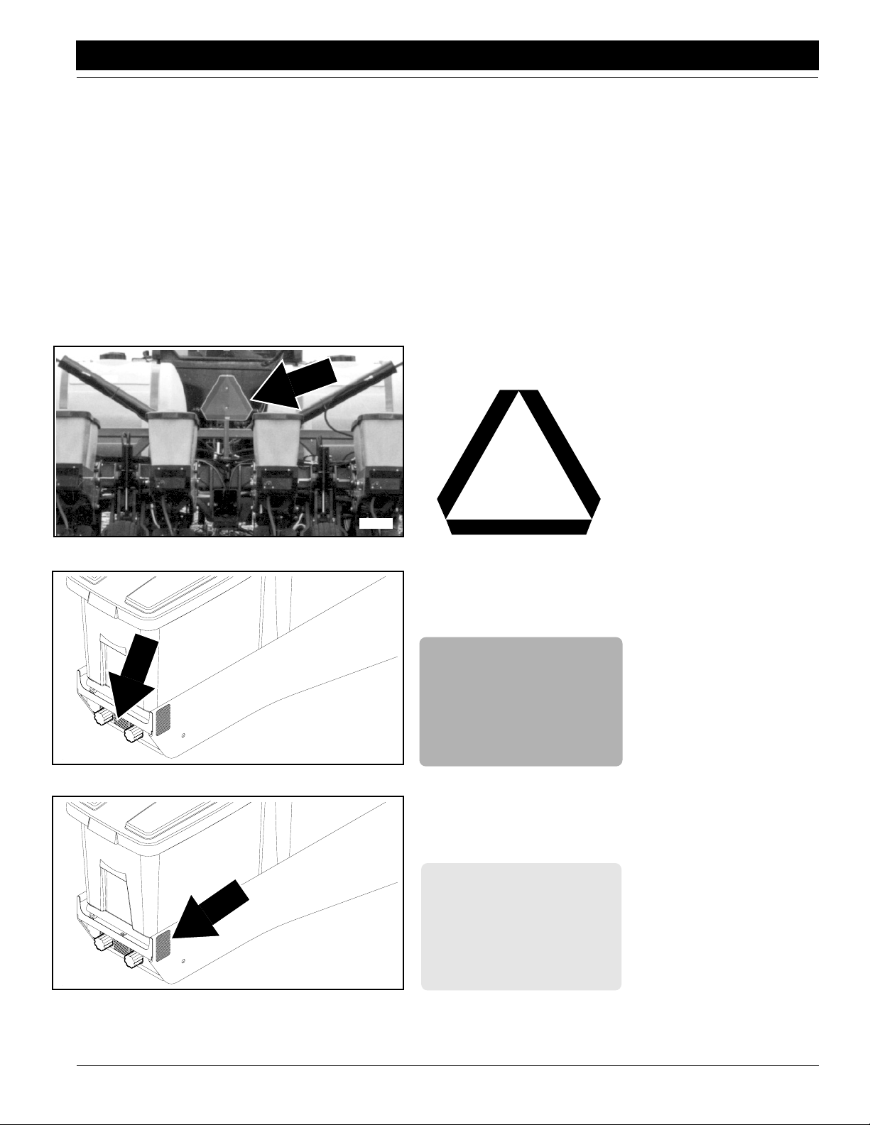
Slow Moving Vehicle Label
10/10/12
15823
15823
818-230C
Red Reflector
One on each outside
mainframe row unit
818-229C
Amber Reflector
One on each outside
mainframe row unit
PT1230 Pull-Type Folding Planter 401-069M-A
4
Page 7
Important Safety Information
Great Plains Mfg., Inc.
15853
15854
818-229C
Amber Reflector
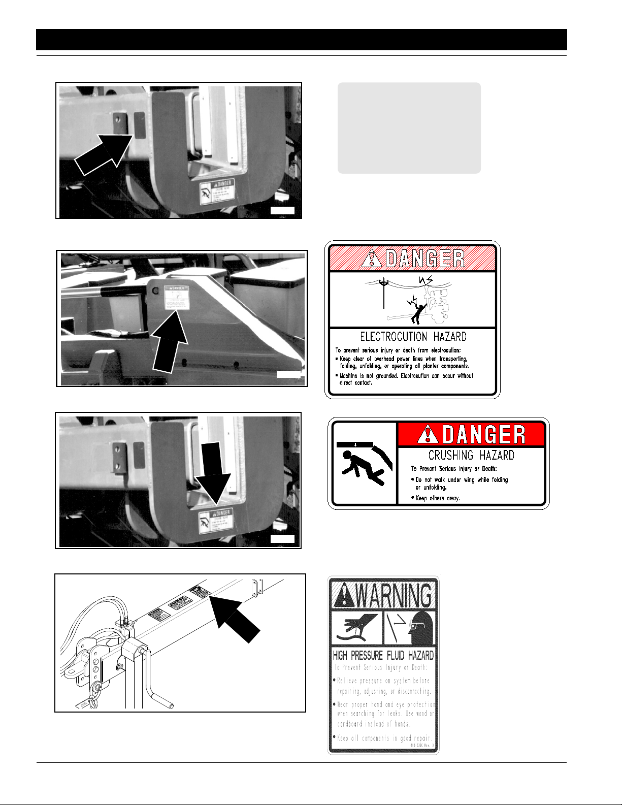
818-765C
Electrocution
15853
15816
PT1230 Pull-Type Folding Planter 401-069M-A 10/10/12
5
Crushing
818-339C
High Pressure Fluid
818-766C
Page 8
Great Plains Mfg., Inc.
Important Safety Information
16861
15816
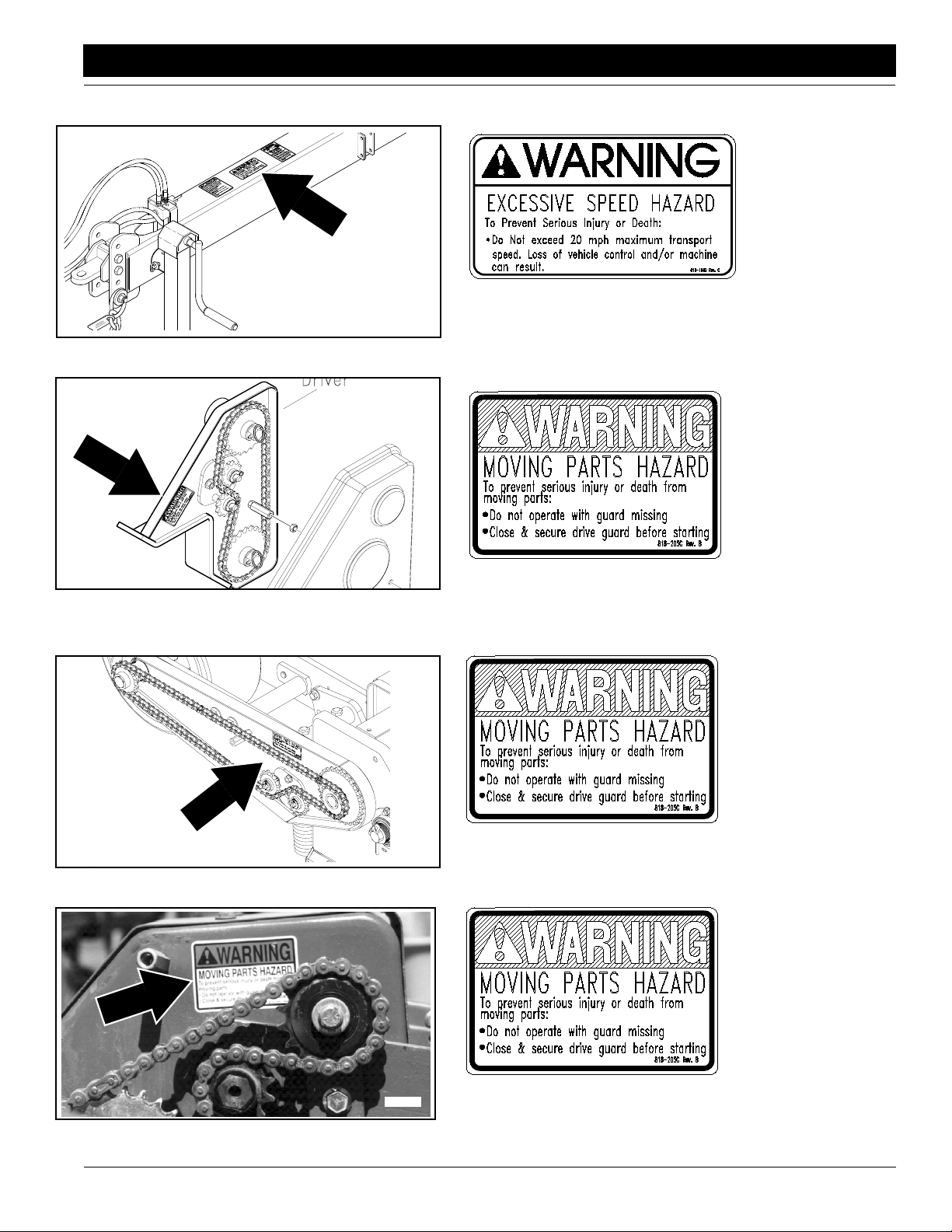
818-188C
Excessive Speed
818-205C
Moving Parts
16863
10/10/12
15720
818-205C
Moving Parts
818-205C
Moving Parts
PT1230 Pull-Type Folding Planter 401-069M-A
6
Page 9
Important Safety Information
Great Plains Mfg., Inc.
15855
15816
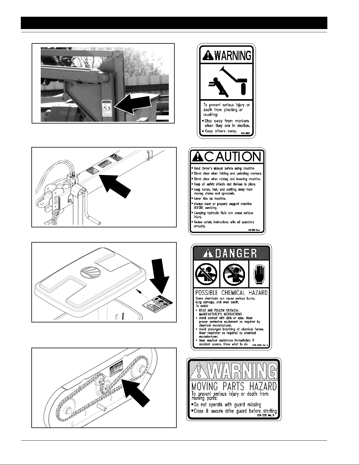
818-682C
Marker Crushing
818-587C
General Safety
15726
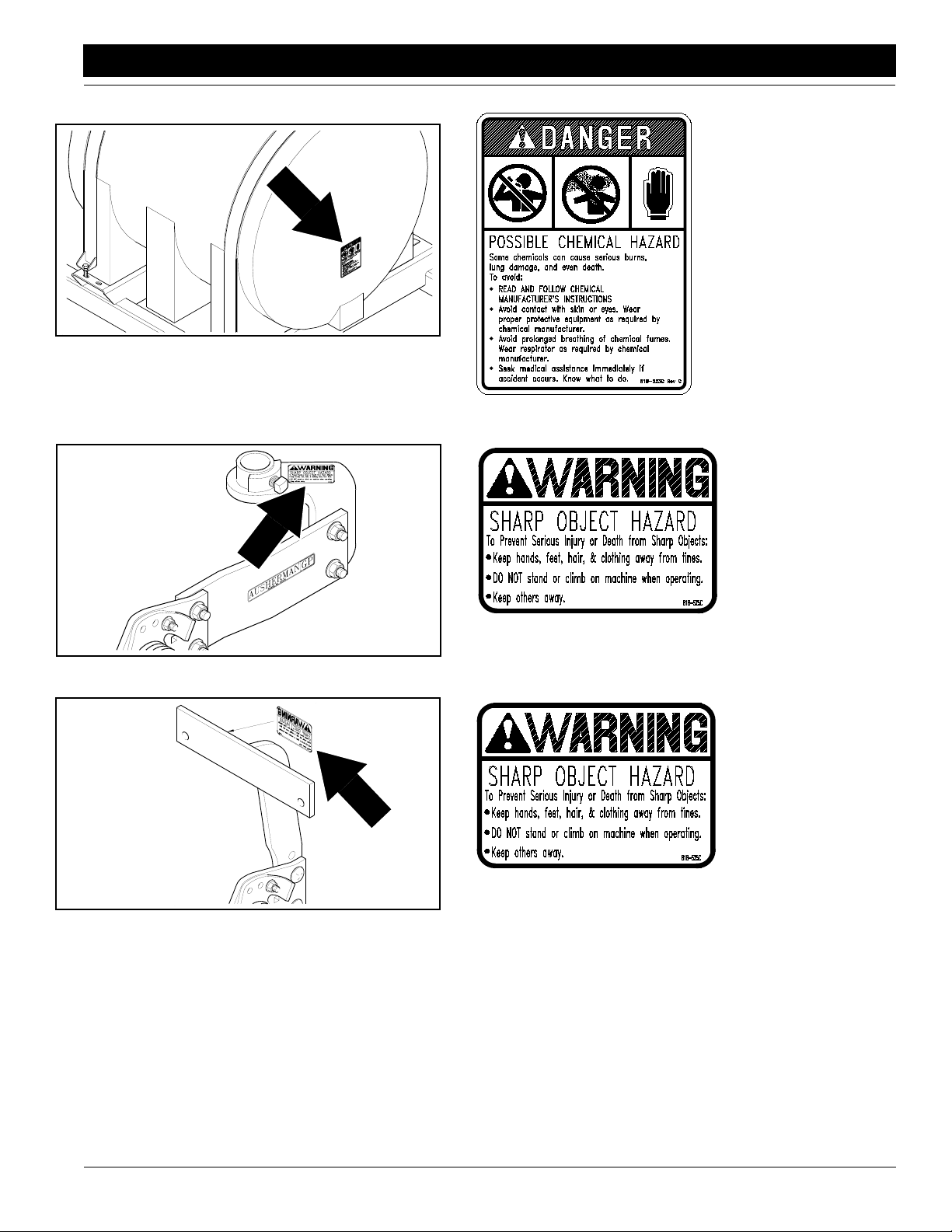
Chemical
818-205C
Moving Parts
818-323C
16864
PT1230 Pull-Type Folding Planter 401-069M-A 10/10/12
7
Liquid Fertilizer
Drive
Page 10
Great Plains Mfg., Inc.
Important Safety Information
15832
818-323C
Chemical
15732
15733
818-525C
Sharp Object
Terra Tine Option
818-525C
Sharp Object
Terra Tine Option
10/10/12
PT1230 Pull-Type Folding Planter 401-069M-A
8
Page 11

Introduction
Introduction
Great Plains Mfg., Inc.
Great Plains welcomes you to its growing family of new
product owners. This implement has been designed with
care and built by skilled workers using quality materials.
Proper setup, maintenance and safe operating practices
will help you get years of satisfactory use from the ma
chine.
-
Description of Unit
The 12-row, 30-inch spacing, pull-type planter has six rigid
center rows and 3 rows on each end which float indepen
dently in field operation. The outer 3 rows on each end lift
and fold above the center rows for transporting. Field turns
can be completed in a relatively small radius due to the lift
wheels and short tongue.
The PL1230, liquid fertilizer attachment, allows application of liquid fertilizer and coulter mounting.This complete
system allows you to band liquid fertilizer on 12 rows with
two 230-gallon liquid tanks and an optional squeeze
pump.
Features include:
• Constant tongue weight in both field and transport posi-
tions.
• A transmission located on each end of the toolbar, each
engaging six rows.
• 2 bushel, narrow profile seed hoppers.
• Electric clutch to allow shut off of right or left side row
units.
• Safety lights which couple with the tractor's lighting sys-
tem.
Intended Usage
This machine is intended for planting row crops in conventional as well as no-till conditions.
Using This Manual
This manual will familiarize you with safety, assembly, operation, adjustments, troubleshooting and maintenance.
Read this manual and follow the recommendations to help
ensure safe and efficient operation.
The information in this manual is current at printing. Some
parts may change to assure top performance.
Definitions
The following terms are used throughout this manual.
Right-hand and left-hand as used in this manual are determined by facing the direction the machine will travel while
in use unless otherwise stated.
IMPORTANT: A crucial point of information related to
the preceding topic. For safe and correct operation,
read and follow the directions provided before continuing.
Owner Assistance
If you need customer service or repair parts, contact a
Great Plains dealer. They have trained personnel, repair
parts and equipment specially designed for Great Plains
products.
Your machine’s parts were specially designed and should
only be replaced with Great Plains parts. Always use the
serial and model number when ordering parts from your
-
Great Plains dealer. The serial-number plate is located on
the planter main frame as shown in Figure A.
Figure A
Serial Number Plate Location
Record your drill model and serial number here for quick
reference:
Model Number: _________________________________
Serial Number: _________________________________
Your Great Plains dealer wants you to be satisfied with
your new machine. If you do not understand any part of
this manual or are not satisfied with the service received,
please take the following actions.
1. Discuss the matter with your dealership service manager. Make sure they are aware of any problems so
they can assist you.
2. If you are still not satisfied, seek out the owner or general manager of the dealership.
3. For further assistance write to:
Product Support
Great Plains Mfg. Inc., Service Department
PO Box 5060
Salina, KS 67402-5060
15856
NOTE: Useful information related to the preceding topic.
PT1230 Pull-Type Folding Planter 401-069M-A 10/10/12
9
Page 12
Great Plains Mfg., Inc.
Section 1 Planter Preparation and Setup
Section 1 Planter Preparation and Setup
Planter Preparation
• Lubricate the planter as indicated in the Lubrication por-
tion of “Section 7 Maintenance and Lubrication” on
page 43.
• Check the chains for proper tension and alignment as
shown in
on page 43.
• Perform all beginning of season and daily planter ser-
vice as discussed in “Section 7 Maintenance and Lubrication” on page 43.
• Check over the planter and replace worn or damaged
parts before going to the field.
• All nuts, bolts and screws should be checked. Refer to
the
pendix” on page 63.
• Inflate tires as recommended on Tire Inflation Chart,
Appendix,
Hitching the Tractor to the Planter
Use the jack to raise and lower the front of the planter
when hitching to the tractor, and store it in the storage tube
on the top of the tongue as shown in
“Section 7 Maintenance and Lubrication”
Torque Values Chart for Common Bolt Sizes in “Ap-
page 63.
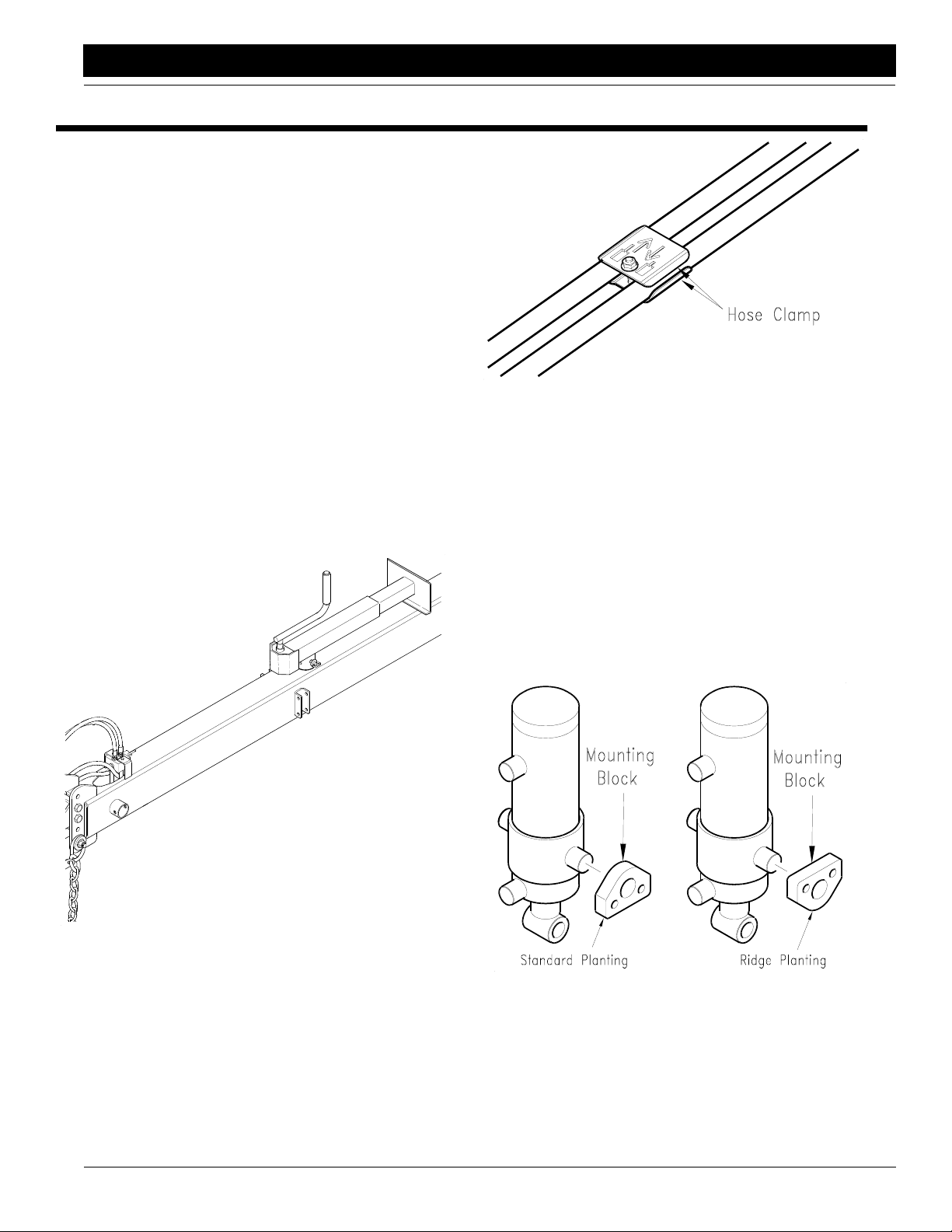
Figure 1-1.
15831
Hose Clamp
Figure 1-2
If tractor couplers are not marked, connect couplers so
moving the hydraulic lever forward lowers planter and
moving the lever back raises planter.
Ridge Planting
Refer to Figure 1-3.
To lower the wheel for ridge planting, invert the cylinder
mounting blocks.To invert, first block under the frame to re
move weight from tires, remove the four 5/8” cap screws.
Invert mounting blocks and install cap screws. Torque per
specifications, see
Sizes in “Appendix” on page 63.
Torque Values Chart for Common Bolt
-
15818
Jack in Storage Position
Figure 1-1
Your planter is equipped with a hitch safety chain. The
safety chain should be securely attached to the planter
hitch and the tractor whenever towing or planting.
Hydraulic Hose Hookup
Plug in implement hydraulic remote couplers by observing
hydraulic cylinder raise and lower symbols on hose clamp,
Figure 1-2. Plug extend symbol on planter in extend
see
symbol on tractor.
10/10/12
Ridge Planting Adjustment
Figure 1-3
NOTE: Changing the mounting height of the transport
wheels also affects the operating height of the planter.
When inverting the cylinder mounting blocks, consider
planter height and levelness. Use hitch-height adjust
ments, not transport-wheel adjustments, to level planter.
Refer to Leveling the Planter,
PT1230 Pull-Type Folding Planter 401-069M-A
page 11.
14958
-
10
Page 13
Section 1 Planter Preparation and Setup
Great Plains Mfg., Inc.
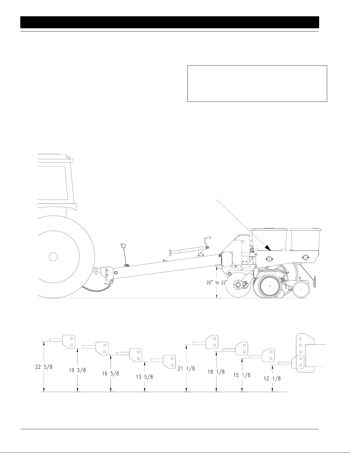
Leveling the Planter
During initial setup and periodically throughout the planting season, check that the planting units are running level.
When planting, the top of the hopper support panel (1)
should be parallel to the ground as shown in
To level the planter, the bottom of the main frame tube
must run between 20 and 22 inches above ground when
lowered into planting position. See
Figure 1-4.
To obtain the correct height, reposition the planter hitch on
the tongue. Proper tongue adjustment improves seed
placement by allowing the row units to operate parallel to
the ground.
The mounting holes in the hitch have been offset so the
Top of Hopper Support Level with Ground
Figure 1-4.
hitch can be turned over and bolted on in four positions,
giving eight possible hitching positions. Use the screw jack
to raise the front of the planter tongue. Adjust the planter
hitch to match your tractor drawbar. See
Figure 1-5.
IMPORTANT: When hitching the planter to a different
tractor, check for a difference in drawbar heights. If
the heights are different, re-adjust height accordingly.
Achieving correct planter position can be difficult with
some attachment combinations, especially when planting
in hard to penetrate soils. Avoid using more attachment
down force than is required.
Leveling the Planter
Figure 1-4
Hitch Positions
Figure 1-5
PT1230 Pull-Type Folding Planter 401-069M-A 10/10/12
11
14956
15819
Page 14
Great Plains Mfg., Inc.
Section 2 Planter Operation
Section 2 Planter Operation
Folding
!
DANGER!
Keep others away during folding operations. Do not walk under
wings when folding planter. See
attempting to unfold planter.
Folding is best achieved on level ground with the tractor
transmission in neutral. Be aware of the clearance re
quired to fold the planter.
!
DANGER!
Keep clear of overhead power lines when folding planter and/
or markers.
Figure 2-6 on page 14 before
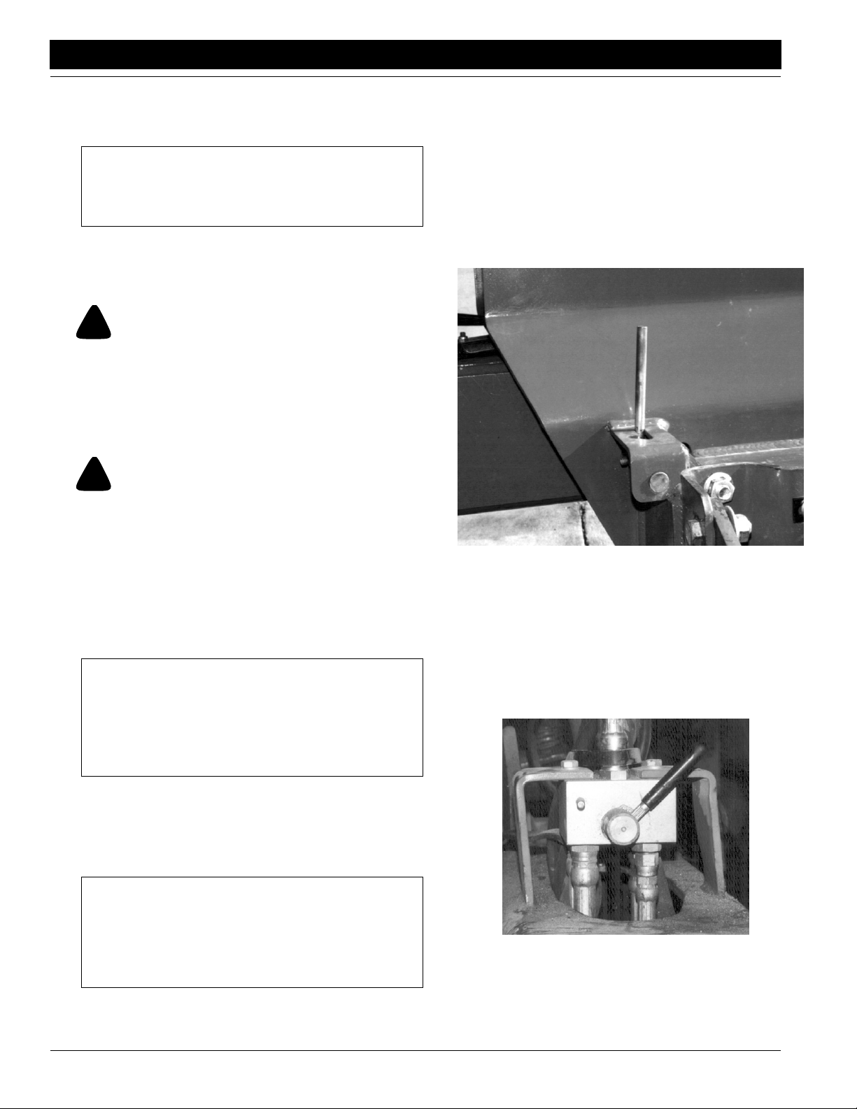
-
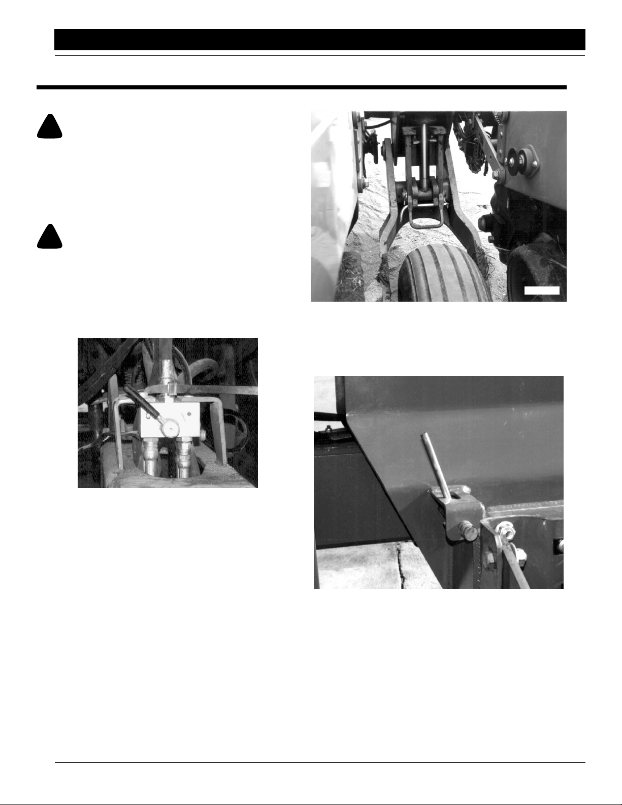
1. Lift planter.
2. Switch hydraulic selector valve from “Field” to “Road”.
Figure 2-1.
See
15857
Hydraulic Selector Valve in “Road” Position
Figure 2-1
3. Secure the four cylinder locks on the center section as
shown in
module cylinder rods. Install bent pin and secure with
hairpin clip.
Figure 2-2. Pivot lock into position on wheel
16889
Cylinder Locks Secured
Figure 2-2
4. Pull out wing lock pins. See Figure 2-3.
10/10/12
15859
Arm Wing Lock Pin in Unlocked Position
Figure 2-3
5. Start folding. The drive shaft will automatically disconnect as planter is folding.
PT1230 Pull-Type Folding Planter 401-069M-A
12
Page 15
Section 2 Planter Operation
Great Plains Mfg., Inc.
6. After wings are off the ground, lower planter. This will
retract the wing gauge wheels. The cylinder locks will
keep planter from lowering to the ground.
IMPORTANT: It is important that the wing gauge
wheels are retracted before continuing to fold the
planter. Failure to retract wheels will lead to hopper
damage.
7. Continue folding until wings are positioned above the
planter main frame.
Unfolding
!
DANGER!
Keep others away during unfolding operations. Do not walk under wings when unfolding planter. See Figure 2-6 on page 14
before attempting to unfold planter.
Unfolding is best achieved on level ground with the tractor
transmission in neutral. Be aware of the clearance re
quired to unfold the planter.
!
DANGER!
Keep clear of overhead power lines when unfolding planter
and/or markers.
-
5. When wing gauge wheels contact the ground, pull
planter ahead a few feet while continuing to lower.
This will level wings.
6. Remove the cylinder locks by removing the bent pins
and pivoting the locks off the cylinders. Replace the
bent pin to keep the locks off the cylinder.
7. Position arm wing lock pins as shown, see Figure 2-4.
If wings are not level, it may be necessary to pull forward a few feet to lock wing lock pins.
NOTE: If unfolding planter with hoppers fully loaded, you
will need a tractor with at least 1900 psi hydraulic pres
sure.
1. Make sure hydraulic selector valve is in the “Road” position. See Figure 2-1 on page 12.
IMPORTANT: If the planter has set in the folded position for awhile, be sure the wing gauge wheels are
fully retracted before beginning to unfold planter. If
wheels are not retracted hopper damage will occur
when unfolding planter. Retract wheels by lowering
planter on transport locks.
2. Begin to unfold planter.
3. When wings have cleared the outside hopper on the
center section, raise planter. This will lower the wing
gauge wheels.
IMPORTANT: Make sure the wings have cleared the
outside hopper on the center section before raising
the planter. If raised too soon, the gauge wheels will
cause hopper damage.
-
Arm Wing Lock Pin in Locked Position
15861
Figure 2-4
8. Connect drive shaft by removing keeper pin on one
end of the drive shaft. Slide drive shaft together and
reinstall keeper pin.
9. Before operating planter be sure to place hydraulic selector valve in “Field” position. See Figure 2-5.
15862
Hydraulic Selector Valve in “Field” Position
Figure 2-5
4. Continue unfolding planter.
PT1230 Pull-Type Folding Planter 401-069M-A 10/10/12
13
Page 16
Great Plains Mfg., Inc.
Section 2 Planter Operation
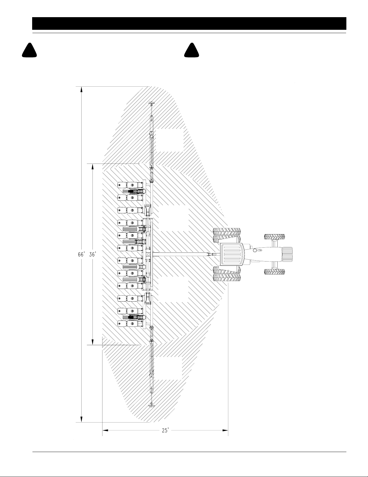
!
DANGER!
Shaded areas in Figure 2-6 indicate approximate danger zones.
Keep away and keep others away from these areas when unfolding or folding planter and/or markers.
Marker
Danger
Zone
Planter
Danger
Zone
!
DANGER!
Keep clear of overhead power lines when folding or unfolding
planter and/or markers.
15778
10/10/12
Planter
Danger
Zone
Marker
Danger
Zone
Folding/Unfolding Danger Zones
Figure 2-6
PT1230 Pull-Type Folding Planter 401-069M-A
14
Page 17
Section 2 Planter Operation
Transporting
!
CAUTION!
Do no exceed 20 mph maximum transport speed.
Before transporting the planter check the following items.
1. Transport only with a tractor of proper size. See Tr ac-
tor Requirements in “Section 9 Specifications and
Capacities” on page 61.
2. Hitch planter securely to tractor. Always use a locking
style drawbar pin sized to match the holes in the hitch
and drawbar (minimum of 1" diameter heat treated
pin).
3. Attach safety chain securely to the planter hitch and
the tractor with enough slack in the chain to permit
turning.
4. Plug in safety lights with tractor lights using the standard 7-pin terminal.
5. It is recommended that the planter not be transported
with full hoppers.
6. Make sure the planter is properly folded. Refer to Fold-
ing on page 12.
7. Any time you transport planter, be sure transport locks
are in place.
8. Check to see that the tires on the planter have the
proper inflation, see the
flation Chart” on page 63.
9. Remember, the planter is wider than the tractor and
extreme care must be taken to allow for safe clear
ance.
10. Transport slowly over uneven or rough terrain.
!
CAUTION!
Folded planter will have a high center of gravity. Use caution
when traveling on an uneven surface.
11. Comply with all federal, state and local safety laws
when traveling on public roads.
Tire Inflation Chart in “Tire In-
Parking
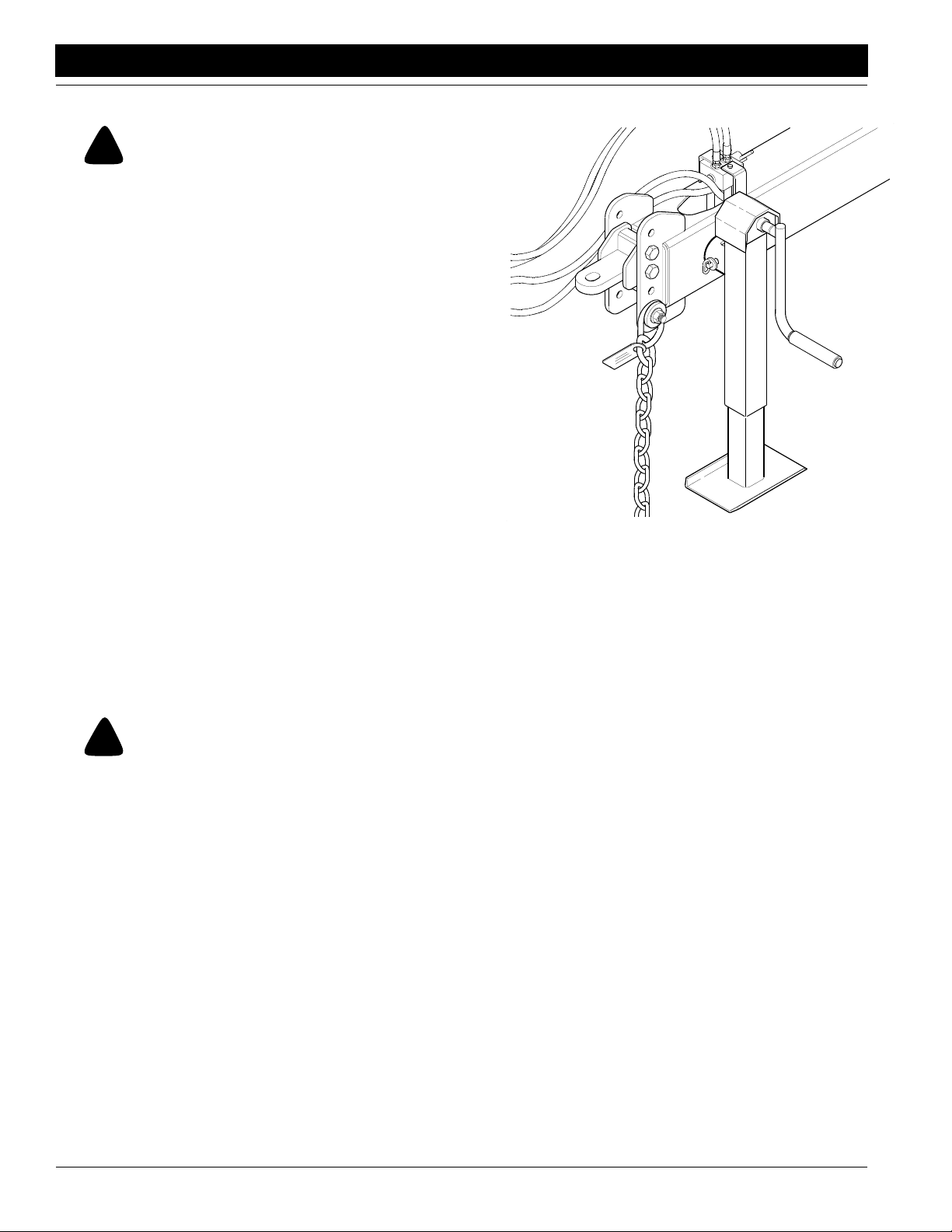
Unhitching with the planter unfolded.
1. Remove the jack from its storage location on top of the
tongue and pin it in the post located on the left side of
the tongue, refer to
weight of the tongue is on the jack.
Figure 2-7. Extend the jack until
Great Plains Mfg., Inc.
15817
Jack in Parking Position
Figure 2-7
2. Make certain that all hydraulic hoses have pressure
relieved before disconnecting. Unplug the planters’
hydraulic lines and electrical lines from the tractor.
-
3. Remove the hitch pin and safety chain from the tractor
drawbar.
Unhitching with the planter folded.
1. Fully raise the planter and install transport locks. Refer to Installing Transport Locks, Maintenance and
Lubrication,
2. Park the planter on a level, solid area.
3. Remove the jack from its storage location on top of the
tongue and pin it in the post located on the left side of
the tongue, refer back to
until weight of the tongue is on the jack. If the ground
is soft, place a board or plate under the jack to widen
the ground contact area.
4. Make certain that all hydraulic hoses have pressure
relieved before disconnecting. Unplug the planters’
hydraulic lines and electrical lines from the tractor.
5. Remove the hitch pin and safety chain from the tractor
drawbar.
page 43.
Figure 2-7. Extend the jack
PT1230 Pull-Type Folding Planter 401-069M-A 10/10/12
15
Page 18
Great Plains Mfg., Inc.
Section 2 Planter Operation
Rephasing the Hydraulic System
!
WARNING!
Escaping fluid under pressure can penetrate the skin causing
serious injury. Avoid the hazard by relieving pressure before
disconnecting hydraulic lines. Use a piece of paper or cardboard, NOT BODY PARTS, to check for suspected leaks. Wear
protective gloves and safety glasses or goggles when working
with hydraulic systems. If an accident occurs, see a doctor immediately. Any fluid injected into the skin must be surgically removed within a few hours or gangrene may result.
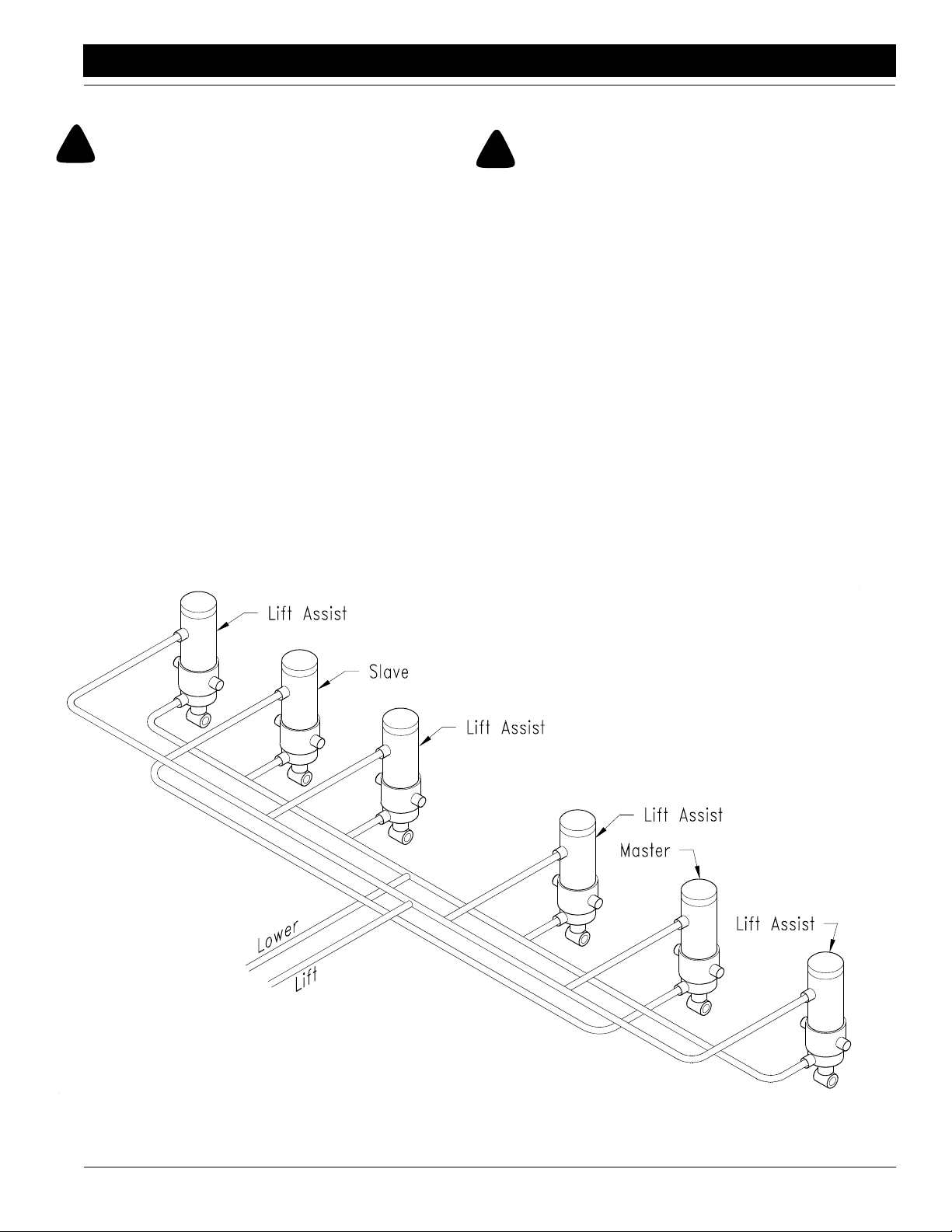
Refer to Figure 2-8:
The lift system on your Great Plains Pull-Type Planter is a
master/slave system. All cylinders in the system are 2/way
cylinders. Rephasing the system is accomplished each
time the planter is lowered to the planting position. If unlevel lifting occurs, lower the planter to the ground and hold
the remote lever momentarily. This time will allow oil to go
from the tractor to the master, bypass to the master, bypass to the slave, then return to the tractor.
Marker Hydraulics
!
DANGER!
Never allow anyone near the planter when cycling the markers.
Excessive travel speed of the markers can be dangerous and/or
damage the marker assembly.The flow controls should be properly adjusted before the marker assembly is first put into use.
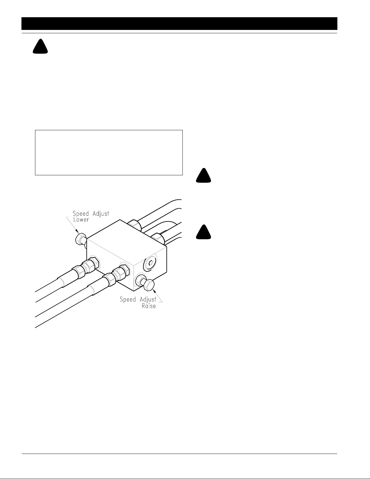
Refer to Figure 2-9:
The marker hydraulic system is equipped with needle
valves to control how fast each marker operates. The needle valves are built into the sequence valve body. There
are two hex adjustment heads, one for controlling marker
speed up and one for controlling marker speed down. To
adjust the speed of each marker, loosen jam nut, screw
the needle valve clockwise to adjust the marker speed to a
low setting. Fold the marker up and down a few times and
recheck for pinching and kinking of hoses. With the tractor
engine at an operating rpm, adjust the needle valve to limit
the marker to a safe operating speed. Excessive folding
speeds can cause marker damage.
10/10/12
Rephasing the Hydraulic System
Figure 2-8
15806
PT1230 Pull-Type Folding Planter 401-069M-A
16
Page 19
Section 2 Planter Operation
!
WARNING!
Escaping fluid under pressure can penetrate the skin causing
serious injury. Avoid the hazard by relieving pressure before
disconnecting hydraulic lines. Use a piece of paper or card
board, NOT BODY PARTS, to check for suspected leaks. Wear
protective gloves and safety glasses or goggles when working
with hydraulic systems. If an accident occurs, see a doctor im
mediately. Any fluid injected into the skin must be surgically removed within a few hours or gangrene may result.
IMPORTANT: JIC fittings do not require high torque.
JIC and O-Ring fittings do not require sealant. To
avoid possible danger of cracking hydraulic fittings
from over tightening, do not use plastic sealant tape.
Great Plains Mfg., Inc.
the hydraulic lever and lower the opposite marker. Holding the lever down then will force both markers down.
If the markers are down they can both be raised simultaneously but they can only be lowered one at a time al-
-
ternating from one side to the other.
• When oil is cold, hydraulics operate slowly. Make sure
-
all adjustments are made with warm oil.
• On a tractor where the oil flow cannot be controlled, the
rate of flow of oil from the tractor may be greater than the
rate at which the marker cylinder can accept it. The trac
tor hydraulic control lever will have to be held until the
cylinder reaches the end of its stroke. This occurs most
often on tractors with an open center hydraulic system.
On tractors with a closed center hydraulic system, the
tractor’ s hydraulic flow control can be set so the tractor’s
detent will function properly.
-
Marker Transporting
!
DANGER!
Keep clear of overhead power lines when folding or unfolding
markers. See also
Figure 2-6 on page 14.
Flow Control Raise/Lower
Figure 2-9
General Notes
15029
• If both markers are required down at the same time run
one marker down, momentarily start to raise it, reverse
Always transport markers folded in the flat fold position.
Liquid Fertilizer Attachment
!
DANGER!
Agricultural chemicals can be dangerous if not selected and
handled with care. Always read and follow directions supplied
by the chemical manufacturer.
Squeeze Pump
Specifications:
Maximum speed - 125 RPM
Maximum pressure - 5 PSI
Output per revolution
5/16 Diameter hose - 0.58 gpm
1/2 Diameter hose - 1.4 gpm
Pump Mounting and Hose Arrangement
The pump should always be mounted even with or lower
than the fertilizer tank and for accurate metering, the
speed should not exceed 125 RPM.
PT1230 Pull-Type Folding Planter 401-069M-A 10/10/12
17
Page 20
Great Plains Mfg., Inc.
Section 2 Planter Operation
!
CAUTION!
Avoid pressure when using the quick fill attachment, see Figure
2-10. The rubber plugs installed in the manifold may be forced
out under pressure.
Quick Fill
Attachment
Shut-off valves provided at various locations should be
closed to shut off flow when the planter sets overnight or
for extended periods of time. It is also important to close
the tank valves whenever service on the pump or hoses is
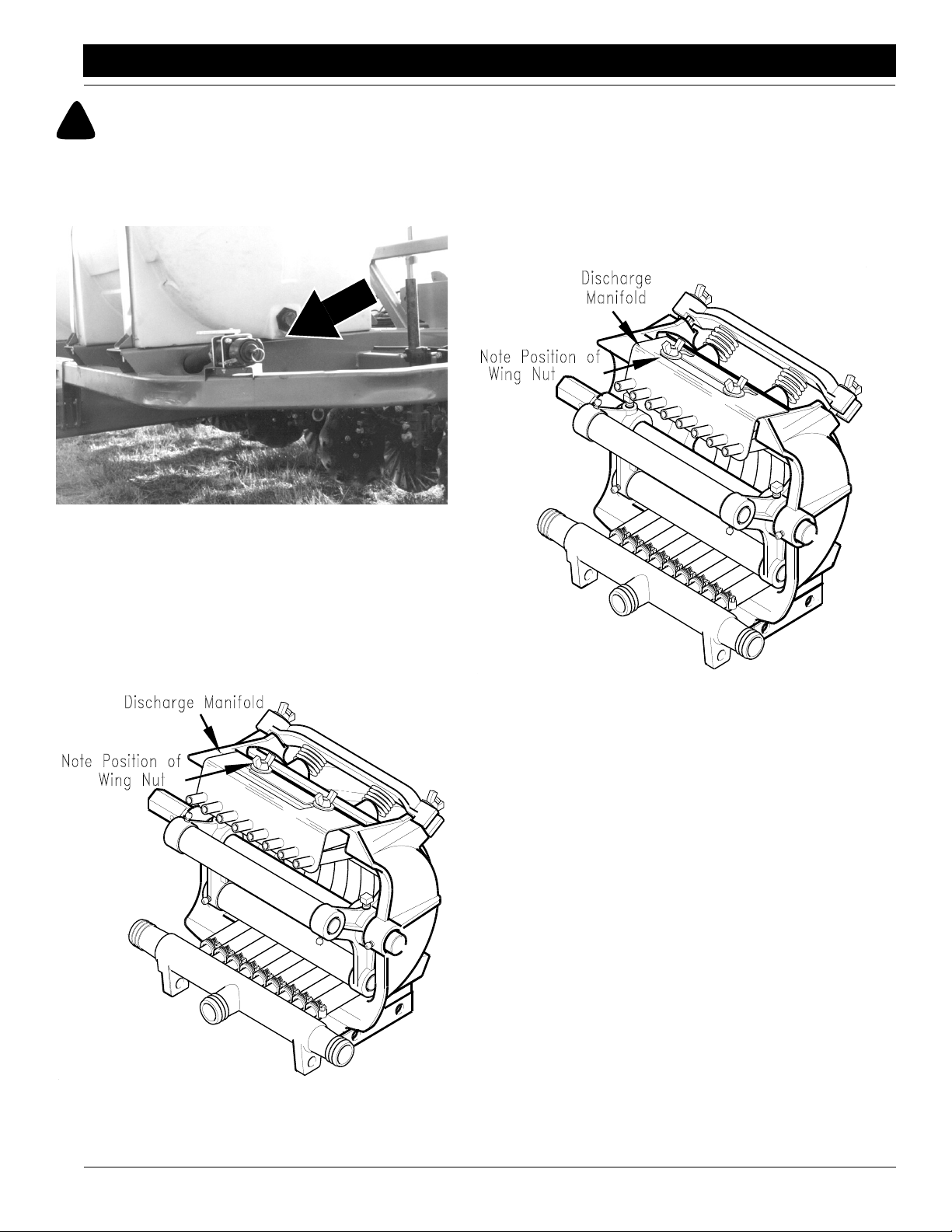
being performed. To prolong the life of the hoses in the
squeeze pump, the discharge manifold must be reposi
tioned to the rearward position when not in use to prevent
hose distortion. See
Figure 2-12.
-
Quick Fill Attachment
Figure 2-10
The discharge manifold must be in the forward position
when the pump is in operation. Squeeze Pumps are
shipped with the discharge manifold in the rearward or
non-operating position. To reposition the manifold, loosen
the wing nuts and slide the manifold forward and sideways
or rearward as required and retighten nuts. See
Figure 2-11.
16892
Discharge Manifold Rearward Position
Figure 2-12
14950
Discharge Manifold Forward Position
Figure 2-11
10/10/12
14949
PT1230 Pull-Type Folding Planter 401-069M-A
18
Page 21

Section 3 Row Unit Operation
Section 3 Row Unit Operation
Great Plains Mfg., Inc.
This planter may be equipped with either a 12 finger mechanical corn meter, see Figure 3-1, or a brush-type seed
meter, see Figure 3-2.
12341
Finger Pickup Meter
Figure 3-1
NOTE: To extend the life and maximize efficiency of the
finger pickup meter and the brush-type seed meter, sprin
kle 1 teaspoon of powdered graphite on top of the seeds
in the hopper, see
way down to lubricate the meter mechanism.
Figure 3-3. The graphite will work its
Graphite Applied to Top of Seeds
Figure 3-3
Brush Meter
Figure 3-2
15868
15782
Finger Pickup Meter
Refer to the Planting Rates for Finger Pickup Corn Meters
in “Section 5 Planting Rate Adjustments” on page 30
for adjusting the planting rates and sprocket combinations.
For more information on the meter, see “Section 6 Trou-
bleshooting” on page 39 & “Section 7 Maintenance
and Lubrication” on page 43.
Brush Meter
The seed discs available for use with the brush meter are
as follows:
• Soybean (black color-coded): 60 cells to meter seed siz-
es from 2200 to 4000 seeds per pound.
• Specialty soybean (dark blue color-coded): 48 cells to
meter seed sizes from 1400 to 2200 seeds per pound.
• Small milo/grain sorghum (red color-coded): 30 cells to
meter seed sizes from 14,000 to 20,000 seeds per
pound.
• Large milo/grain sorghum (light blue color-coded): 30
cells to meter seed sizes from 10,000 to 16,000 seeds
per pound.
• High rate small milo/grain sorghum (red color-coded):
60 cells to meter seed sizes from 12,000 to 18,000
seeds per pound.
• High rate large milo/grain sorghum (yellow color-cod-
ed): 60 cells to meter seed sizes from 10,000 to 14,000
seeds per pound.
-
• Cotton, acid-delinted (white color-coded): 30 cells to
meter seed sizes from 4200 to 5200 seeds per pound.
• Large cotton, acid-delinted (tan color-coded): 36 cells to
meter seed sizes from 3800 to 4400 seeds per pound.
• High rate cotton, acid-delinted (light green color-coded):
48 cells to meter seed sizes from 4200 to 5200 seeds
per pound.
• Hill-drop cotton, acid-delinted (brown color-coded): 12
cells, 3 to 6 seeds/cell, to meter seed sizes from 4000 to
5200 seeds per pound.
To install the seed disc onto the meter hub, turn the disc
counterclockwise while tightening the two wing nuts that
retain the disc. After the wing nuts are tight make sure the
seed disc has only slight resistance when it is rotated
counterclockwise.
Clean seed should be used to assure accurate seed metering. Brush meter seed discs should be removed and
checked daily for buildup of foreign material in the seed
meter or brushes. Foreign material, such as hulls, stems,
etc., may affect seed delivery.
Refer to the Planting Rates for Brush Meters in “Section
5 Planting Rate Adjustments” on page 30 for adjusting
the planting rates and sprocket combinations.
Read and follow the seed manufacturers’ recommendations when using seed treatment.
For more information on the meter, see “Section 6 Trou-
bleshooting” on page 39 & “Section 7 Maintenance
and Lubrication” on page 43.
PT1230 Pull-Type Folding Planter 401-069M-A 10/10/12
19
Page 22

Great Plains Mfg., Inc.
Section 3 Row Unit Operation
Meter Clutches
To disengage either the seed hopper clutch or the chemical hopper clutch pull the knob and rotate 90 degrees
clockwise or counter-clockwise until the roll pin aligns with
the indentations in the end of the drive hub then release
knob. See
To engage the clutches, pull and rotate the knob until the
roll pin aligns with the drive hub slot then release.
Figure 3-4.
Disengage Meter Clutch
Figure 3-4
16868
Point Row Clutch
Mount the Point Row Clutch control box, Figure 3-5, at a
convenient location in the tractor cab.
Control Box Wiring Hookup
Figure 3-6
15878
Point Row Clutch Control Box
Figure 3-5
15875
Attach all wiring connections as shown in Figure 3-6.
Refer to Figure 3-7:
The power cord must be connected directly to the battery
on the tractor. The red wire is a fused connection so make
sure it is connected to the positive post on the battery.
10/10/12
Battery Lead Connection
Figure 3-7
PT1230 Pull-Type Folding Planter 401-069M-A
15876
20
Page 23

Section 3 Row Unit Operation
Seed Hopper
The row unit is equipped with one 2-bushel translucent
seed hopper.
Before filling the seed hopper, clear it of foreign objects.
After filling the hopper with clean seeds always replace the
hopper lid. Operating with the lids attached prevents ob
jects from entering the hopper and also aids in keeping out
moisture.
Empty the contents of the hopper periodically to avoid the
collection of dirt and other materials. To remove the hop
per, disengage the meter drive clutch and the hopper
latch, see
Figure 3-8.
Great Plains Mfg., Inc.
IMPORTANT: To install Lock ‘n Load®, you must install lid stiffeners. Stiffeners are available through
Great Plains, part number 403-075K.
-
-
Meter Clutch & Seed Hopper Latch
Figure 3-8
15784
Chemical Hopper
The optional chemical hopper, see Figure 3-9, comes in 2
versions:
• 1 chemical meter and an approximately 70 lb. capacity
translucent hopper.
• 2 chemical meters and 1 divider that separates the 70 lb.
hopper into 2 compartments - approximately 35 lbs.
each.
Before filling each chemical hopper clear it of foreign objects. After filling each hopper replace the hopper lid. Operating with the lid attached prevents objects from entering
the hopper and also aids in keeping out moisture.
Chemical Hopper
Figure 3-9
The application rate is determined by:
1. The size of the opening on the meter housing assembly.
2. The travel speed.
The size of the opening is adjustable by turning the knobs
on the rear of the granular hoppers. There are 99 incre
ments which indicate the relative application rate. The delivery rate will increase from 1 through 99. Setting 00
closes the opening completely. A fluted roller delivers the
granular chemical to the adjustable opening.
The granular chemical flows through a given opening size
at a nearly uniform rate regardless or rotor rpm. Therefore,
SPEED has the greatest impact on application rate and re
sulting chemical concentration in the row.
For example, if planting speed is reduced from 6 to 3 mph,
chemical concentration will nearly double since the deliv
ery rate through the orifice remains nearly the same while
the distance traveled in a given period of time has been cut
in half. Therefore, twice as much chemical is placed on the
ground due to the decrease in ground speed.
Rotor rpm will minimally change the chemical meter deliv-
15807
-
-
-
PT1230 Pull-Type Folding Planter 401-069M-A 10/10/12
21
Page 24

Great Plains Mfg., Inc.
Section 3 Row Unit Operation
ery rate unless the seed population is changed significantly (i.e. + 25 percent or more from the original setting).
The rate charts starting on page 32 are approximate, and
are based on a planting speed of 5 mph. They are to be
used only as a guide to determine a starting point for the
meter dial setting.
Always check your rate of application as outlined in this
section to be sure you are getting the desired rate.
Use the application rate and meter setting recommended
by the chemical manufacturer as a starting point for the
meter dial setting.
If the meter setting is not available from the chemical manufacturer, use the charts in “Section 5 Planting Rate Ad-
justments” on page 30 as a starting point for the meter
dial setting.
NOTE: Because the available chemical materials vary
widely in consistency and composition, their “flow-ability”
is affected by temperature and humidity conditions. It is
important to calibrate each individual meter to the partic
ular chemical being used.
To determine the application rate and starting meter setting, proceed as follows:
The chemical manufacturer may recommend the rate of
application for granular chemicals in the following ways:
1. Ounces per 1000 linear row feet.
2. Pounds per acre for a given band width and row spacing.
3. Pounds per acre for complete (broadcast) coverage.
When the chemical manufacturer recommends ounces
per 1000 linear row feet or pounds per acre for a given
band width and row spacing, proceed to the chemical
manufacturer’s recommended meter setting or to the
meter setting recommended in the rate charts.
When the chemical manufacturer recommends pounds
per acre for complete (broadcast) coverage only, it is nec
essary to reduce the pounds per acre to apply for your
band width and row spacing. This will give you the same
chemical concentration in the band area as the chemical
manufacturer recommends for complete (broadcast) cov
erage.
Use the following formula to find the pounds per acre for
your band width and row spacing.
A - Chemical manufacturers recommended rate in pounds
per acre for complete (broadcast) coverage.
B - Band width in inches.
C - Row spacing in inches.
Example: The chemical manufacturer recommends 20 lb/
acre for complete broadcast coverage. The band width is
14 inches. The row spacing is 30 inches.
20 x 14/30 = 9.3 lb. per acre.
The required delivery rate for 14 inch bands and 30 inch
row spacing would be 9.3 lb/acre. Set meter setting rec
ommended for 9.3 lb/acre broadcast coverage.
Delivery of 9.3 lb/acre of chemical in a 14 inch band will
provide the same chemical concentration on the soil sur
face as delivery of 20 lb/acre broadcast coverage.
Proceed to chemical manufacturer’s recommended meter
setting or to the meter setting recommended in the rate
charts in this section which will deliver 9.3 lb/acre.
-
To check the exact number of lb/acre of chemical that will
be delivered, attach a plastic bag to each chemical diffus
er, lower the planter, and proceed as follows:
Drive 500 feet at planting speed. Weigh the chemical in oz.
that was caught in one bag. Multiply that amount by the
factor shown to determine lb. per acre.
Check the chemical caught in each bag in the same manner.
Lb. Per Acre Factor for
Given Row Width
Row Width Factor
30 inch 2.2
Example: Assume you are planting 30 inch rows and you
caught 5.6 ounces in one bag (one row).
5.6 ounces times 2.2 equals 12.3 lb. per acre.
If the desired amount is not obtained for each unit with the
first setting, turn the metering knob and repeat the check
until desired amount is delivered.
-
IMPORTANT: If a significant difference in rate is observed between rows, the meter dial mechanism
may require recalibration.
-
-
-
IMPORTANT: We recommend you actually measure
the band width applied in your conditions and use
this width in your application rate calculations.
A X B/C = Delivery rate per acre for a given band width
and row spacing.
10/10/12
Empty the contents of each hopper periodically to avoid
the collection of dirt and other materials. To remove the
hopper, disengage the meter drive clutch and unlatch front
of hopper.
PT1230 Pull-Type Folding Planter 401-069M-A
22
Page 25

Section 3 Row Unit Operation
Great Plains Mfg., Inc.
Recalibrating Chemical Meter
Refer to Figure 3-10:
If it should ever become necessary to recalibrate the granular meter on the insecticide/herbicide hopper, proceed as
follows:
1. Remove and empty hopper and turn hopper upside
down.
2. Turn hopper knob to “10”.
3. Loosen screws (#1) in metering gate.
4. Insert calibration tool (#2).
5. Readjust dial to “04”.
6. Slide gate (#3) to tool.
7. Retighten screws.
8. Reinstall hoppers, refill and check per previous instructions.
Recalibrateng Chemical Meter
Figure 3-10
PT1230 Pull-Type Folding Planter 401-069M-A 10/10/12
23
15785
Page 26

Great Plains Mfg., Inc.
Section 4 Adjustments
Section 4 Adjustments
Marker Disk Adjustments
The aggressiveness and the mark left by the disk may be
changed by two methods:
Refer to Figure 4-1:
1. Disk Angle
To change the angle of cut, loosen the two bolts (1),
rotate the disk assembly and retighten.
2. Direction of Cut
The disk may be mounted to throw dirt either in or out
which will give different marks in different soil conditions. To change the direction of cut:
a. Reverse the blade and depth band by remounting
the four lug bolts on the disk hub.
b. Reverse the angle of the assemble by removing
the adjustment bolts and turning the spindle assembly one half turn. Reinstall and tighten all
bolts.
Refer to Figure 4-2:
Marker width adjustment is made by loosening the marker
tube u-bolt (#1) and sliding marker tube in or out to the desired width.
Disk Angle and Direction of Cut
Figure 4-1
15834
Dimension (A) is measured from the center line of the
planter to the marker disk.
The approximate dimension (A) is 360” and should be
checked in the field.
After adjusting marker, tighten u-bolt.
10/10/12
Marker Disk Adjustment
Figure 4-2
15835
PT1230 Pull-Type Folding Planter 401-069M-A
24
Page 27

Section 4 Adjustments
Contact Drive Wheel Spring
There are two down pressure springs, see Figure 4-3, on
each contact drive wheel. The down pressure is factory
preset and should need no further adjustment.
Contact Drive
Wheel Spring
Contact Drive Wheel Spring
Figure 4-3
Meter Drive Adjustments
The alignment between the meter clutch and the input
shaft is important. If there is misalignment the meter will
not function properly. Excessive wear and damage can
also occur to the meter housings. When replacing the
meter the vertical and horizontal alignment should be
checked.
Check for Vertical Alignment
Refer to Figure 4-4:
1. Latch the appropriate hopper into place on the support.
2. The roll pin in the end of meter input shaft should be
centered (equal distances of the roll pin should protrude from both sides of the shaft).
3. Rotate the input shaft so that the roll pin is vertical.
4. Rotate the drive coupler so that the slots are vertical.
5. Release the clutch to engage the drive coupler with
the input shaft.
If the alignment is correct the coupler will engage with the
shaft freely and the roll pin will extend equally on each side
of the coupler. Disengage the clutch and check the horizontal alignment.
15882
Great Plains Mfg., Inc.
16869
Vertical Alignment
Figure 4-4
Check for Horizontal Alignment
Refer to Figure 4-5:
1. Latch the appropriate hopper into place on the hopper
support.
2. The roll pin in the end of meter input shaft should be
centered (equal distances of the roll pin should protrude from both sides of the shaft).
3. Rotate the input shaft so that the roll pin is horizontal.
4. Rotate the drive coupler so that the slots are horizontal.
5. Release the clutch to engage the drive coupler with
the input shaft.
To adjust alignment:
• With the hopper in place loosen the two 5/16" nuts.
• Engage the clutch to the meter input shaft.
• Align clutch with shaft and tighten 5/16" nuts to torque
values in the Torque Values Chart for Common Bolt Sizes in “Appendix” on page 63.
Horizontal Alignment
Figure 4-5
PT1230 Pull-Type Folding Planter 401-069M-A 10/10/12
25
16870
Page 28

Great Plains Mfg., Inc.
Section 4 Adjustments
Depth Adjustment
The planting depth of the row unit is controlled by 2 walking gauge tires located next to the disks.
Adjust the planting depth as follows:
1. Raise the planter to remove weight from the gauge
tires.
Raise the T-handle and move it forward to decrease the
planting depth, see Figure 4-6. Moving the handle rearward increases the planting depth. Small increments of
depth adjustment can be made by walking the T-handle
from side to side.
T-Handle Adjustment
Figure 4-6
After one row is set to the desired depth, move the T-handle on the other rows to the same location. Field check
each row for desired depth and re-adjust as necessary.
12345
Down Force Row
Standard Spring Package
The standard down force spring package, consists of 2
adjustable springs applying approximately 100-200 lbs. of
down force.
• The spring package is adjustable from 90 lbs. to 325 lbs.
of down force when the parallel arms are horizontal.
Consult the Down Force Pressure Chart to obtain the
desired down force.
IMPORTANT: To adjust the spring tension, lift the
plunger by pulling up on the roll pin handle and sliding
the handle adjustment assembly into the appropriate
hole, see Figure 4-7.
• Two springs can be purchased at your Great Plains
Dealer to make the standard package into a heavy duty
package or two springs can be removed from the heavy
duty package to make a standard package. Add or subtract springs by removing the cotter key at the end of the
spring pivot rod. Slide the rod inward to add or remove a
spring from each side. Then attach or remove the other
spring end on the hex bar support. Reinstall the spring
rod and snap ring on each side.
Down Force Pressure Chart
Refer to Figure 4-7:
To Obtain This
* Down Force
90 lbs. 2 A
105 lbs. 2 B
125 lbs. 2 C
140 lbs. 2 D
160 lbs. 2 E
185 lbs. 4 A
215 lbs. 4 B
245 lbs. 4 C
285 lbs. 4 D
325 lbs. 4 E
* Force when arms are parallel.
Use This # of
Springs
In This
Hole
!
CAUTION!
Adjust spring pressure only with planter in raised position.
Optional Heavy Duty Spring Package
The heavy duty spring packages consist of 2 additional
springs. The heavy duty package can be adjusted from
approximately 200 to 400 lbs. of down force.
Spring Adjustments
• All spring adjustments must be made with the planter in
the fully raised position.
IMPORTANT: The maximum down force stated before is reached when the parallel arms are all the
way up.
10/10/12
Adjustment Bar
Figure 4-7
PT1230 Pull-Type Folding Planter 401-069M-A
12137
26
Page 29

Section 4 Adjustments
Row Unit Mounted Coulter Adjustment
The optional coulter allows the planter to penetrate tough
ground conditions. It is recommended that either the standard or heavy duty spring package be used in conjuction
with this coulter.
Adjust the coulter to run 1-4 to 3/8 inch shallower than the
opener disks. In heavy residue or hard soils, the coulters
may need to run deeper.
Refer to Figure 4-8:
1. To adjust the coulter vertically, loosen the 3/4" jam nut
(#1) and the 3/4" x 3" long hex bolt (#2).
2. By turning the cam hex (#3), rotate the cam casting to
set the desired height.
3. Tighten the bolt and jam nut. Refer to Torque Values
Chart for Common Bolt Sizes in “Appendix” on
page 63.
Great Plains Mfg., Inc.
Closing Wheel Adjuster
Figure 4-9
12346
Coulter Adjustment
15053
Figure 4-8
1 x 12 Closing Wheel Adjustments
The 1 X 12 closing wheel option can be adjusted for down
force, alignment, and offset.
Closing Wheel Down Force Adjustment
Adjust the closing wheel down force to permit proper closing of the seed trench. It is recommended to start with the
T-handle in the first of 4 notches, see Figure 4-9.
If the seed trench is not closing move the handle to the
next notch back and try again. Keep moving the handle
back until the seed trench is closing, by doing this eliminates unnecessary down force and compaction. In some
field conditions, the T-handle can be left in the forward slot
to minimize down force.
Closing Wheel Alignment
Refer to Figure 4-10:
If one closing wheel is running in the seed trench or the
wheels are not centered over the seed trench, adjust the
closing wheels as follows:
1. Raise the planter slightly to remove weight from the
closing wheels.
2. Loosen the two 1/2" bolts.
3. Turn the press wheel adjuster left or right to center the
wheels over the seed trench.
Tighten the 1/2" bolts to the correct torque values in the
Torque Values Chart for Common Bolt Sizes in “Appen-
dix” on page 63.
Closing Wheel Alignment
Figure 4-10
PT1230 Pull-Type Folding Planter 401-069M-A 10/10/12
27
12418
Page 30

Great Plains Mfg., Inc.
Section 4 Adjustments
Closing Wheel Offset
The 1x12 wheels can be offset to help prevent trash from
plugging the closing wheels. If the closing wheels are not
offset, the wheels should be located in the front holes of
the press wheel arm.
To offset the wheels, do as follows:
1. Raise planter slightly to remove weight on the closing
wheels.
2. Remove the bolt holding the wheel, see
Figure 4-11.
3. Move the wheel to the rear hole and attach with the
bolt. Tighten the bolt to the correct torque value listed
in the Torque Values Chart for Common Bolt Sizes in
“Appendix” on page 63.
Closing Disk Tube Shield
Refer to Figure 4-13:
To prevent clogging in insecticide hoses:
1. Clamp closing disk tube shield to closing disk with
hose clamp provided.
2. Insert insecticide hose (#1) inside the closing disk
tube shield (#2) as shown. When unit is picked up, the
insecticide hose should be about 1/4” above the bottom of the shield.
Closing Wheel & Offset
Figure 4-11
12347
Closing Disk Adjustments
The closing disk options consists of two disks and a
6 1/2 x 12 press wheel. The disk down pressure can be adjusted to provide closing of the seed trench.
To select one of four down pressure settings, ratchet the
spring cam to the next cam height by turning the head of
the support bolt clockwise. Refer to Figure 4-12.
Closing Disk Tube Shield
Figure 4-13
15717
Liquid Fertilizer Adjustments
If ‘A’ or ‘B’ hose (end hoses) should run off the back, realign hoses as follows:
1. ‘A’ Hose - Loosen hose clamp on intake manifold and
twist hose 1/4 turn in a counter-clockwise direction.
2. ‘B’ Hose - Loosen hose clamp on intake manifold and
twist hose 1/4 turn in a clockwise direction.
3. Retighten hose clamp.
10/10/12
Closing disk & Tube Holes
Figure 4-12
15830
Hose Alignment
Figure 4-14
PT1230 Pull-Type Folding Planter 401-069M-A
12402
28
Page 31

Section 4 Adjustments
Great Plains Mfg., Inc.
Seed Lok® (Optional)
The Seed Lok® option provides additional seed to soil
contact. The Seed Lok® is spring loaded and does not require adjusting. In some wet and sticky conditions the
wheel may accumulate soil and may require removal of
the Seed Lok® until conditions improve.
The Seed Lok® is attached to the shank with a 1/2” clevis
pin, see Figure 4-15. To remove the Seed Lok®, remove
the clevis pin and pull down on the Seed Lok® mount.
Reattach in the reverse order.
Tire Scraper (Optional)
Some soil types may require the use of the optional tire
scraper. The scraper prevents an excess of mud from
building up on lift tire that may hamper the contact drive
tire. Adjust the scraper so it does not contact the tire. See
Figure 4-16.
Tire Scraper
Figure 4-16
15027
Seed Lok Assembly
Figure 4-15
15883
PT1230 Pull-Type Folding Planter 401-069M-A 10/10/12
29
Page 32

Great Plains Mfg., Inc.
Section 5 Planting Rate Adjustments
Section 5 Planting Rate Adjustments
Planting Rate
Transmission Adjustment
To change planting population, change the sprocket combination on the transmission.
1. Refer to “Planting Rates for Finger Pickup Corn
Meters” on page 32 for the proper sprocket combina-
tion for your desired planting population.
2. Remove the cover from the transmission by loosening
the knob on the cover.
16861
Left-Hand Planter Transmission
Figure 5-1
3. Loosen the carriage bolt and flange nut on the idler
plate. Rotate the idler plate to move the idlers out of
the chain.
4. Remove the chain. Remove sprockets currently on
transmission shafts.
5. Find the correct sprockets on the storage brackets
and place on the transmission shafts.
NOTE: When not in use, store all extra sprockets on the
storage bracket.
6. Place the sprockets on the drive/driven shafts.
7. Re-route chain over idlers and sprockets.
8. Turn the idler plate to take up chain slack. Chain
should have a maximum of 1/4-inch slack.
9. Retighten the carriage bolt and flange nut to secure
idler plate.
10. Replace the transmission cover and hand tighten the
knob.
2-to-1 Drive Reduction
The 15/28 tooth drive sprocket located on the inner side of
the contact drive wheel assembly will give you a 2-to-1
drive reduction and reduce planting rates by about onehalf.
NOTE: After each sprocket combination adjustment, make
a field check to be sure you are planting at the desired
rate.
16863
2-to-1 Drive Reduction
Figure 5-2
Checking Planting Population
After setting the transmission or contact-drive reduction,
always field check the planting population as follows.
1. Release spring pressure on opener disks and wheels.
2. Tie up closing disks and wheels to hopper support using a chain or heavy wire. Pin up optional Seed-Lok
wheels
3. Adjust the planting depth to a shallow setting.
4. Plant at a normal speed for a short distance.
5. For 30-inch rows, measure 17 feet 6 inches (one-thousandth of an acre.)
6. Count the number of seeds in one row over the measured distance.
7. Multiply the number of seeds counted by 1000. This
gives you total population.
Example
• 30-inch row spacing
• Measure 17 feet 6 inches
• 24 seeds over measured distance in one row
24 X1000 = 24,000 plant population per acre
If the planting population is significantly different than the
desired, make the following checks.
• Double check the sprocket combination in the transmission. Refer to the “Planting Rates for Finger
Pickup Corn Meters” on page 32.
• Check air pressure in the gauge wheel tires. Refer to
Tire Inflation Chart,
“Appendix” on page 63.
• Check for meter malfunction or excessive contactdrive-wheel slippage. Refer to
“Section 6 Trouble-
shooting” on page 39.
10/10/12
PT1230 Pull-Type Folding Planter 401-069M-A
30
Page 33

Section 5 Planting Rate Adjustments
Great Plains Mfg., Inc.
Planting Recommendations
To get the best planting results, follow these recommendations:
• Plant at 5 mph
• Add 1 teaspoon of graphite to each seed hopper.
• Maintain tire pressure in the gauge tires and drive tires.
• Replace worn meter parts. Drive Wheel Slippage
Another item that may cause the actual rates of seed or
fertilizer to differ from the delivery rates shown in the oper
ator’s manual is the amount of drive wheel slippage.
While a certain amount of wheel slippage is normal, excessive drive wheel slippage may cause undesirable
changes in the actual rates.
Excessive drive wheel slippage may be caused by binding
or poorly lubricated parts, misaligned bearings or caked
material in the pesticide or fertilizer hoppers.
In addition, down pressure springs, coulters, tine tooth attachments, or any other attachment that removes frame
weight from the drive wheels, may contribute to drive
wheel slippage and lower than expected rates.
If in-field checks indicate that the planter is planting at a
rate significantly different than the seed transmission rate
chart indicates, investigate the following in the order listed:
• Ensure that ALL transmission sprockets are set accord-
ing to the rate chart.
• Excessive unit bounce can cause low population and re-
duced spacing control. Reduce excessive unit bounce
by increasing unit down force, or drive slower.
• Ensure that the planter drive wheel slippage is close to
normal. Variations in drive wheel slippage can be
caused by crop residue, tire inflation pressure, soil con
ditions and unit down force.
Adjusting Granular Chemical Rates
The optional chemical applicators are adjusted by
varying the opening on the chemical meter housing. The
field check is very important because temperature, humid
ity, speed, ground conditions, flowability of chemicals, and
obstructions affect the application rate.
4. Attach a plastic bag to each chemical
diffuser.
5. Drive 1320’ at a normal planting speed.
6. Weigh the contents of the bag in ounces.
7. Multiply ounces by 0.83 to determine the pounds
per acre.
8. If required, adjust the meter setting and repeat steps 3
through 7 until the desired rate is reached.
-
Chemical Meter with Knob
Figure 5-3
Liquid Fertilizer Attachment
!
DANGER!
Agricultural chemicals can be dangerous if not selected and
handled with care. Always read and follow directions supplied
by the chemical manufacturer.
On machines equipped with the squeeze pump option, the
rate of liquid fertilizer application is determined by the
combination of sprockets on the squeeze pump driven and
drive shafts. When changing sprocket combinations,
make sure sprockets are in alignment, sprocket retaining
collars are tight and chain tension is sufficiently restored.
-
The Liquid Fertilizer Rates on page 35 provide an approximate application rate only. Actual delivery will vary with
temperature and the particular fertilizer being used.
14914
!
DANGER!
Agricultural chemicals can be dangerous if not selected and
handled with care. Always read and follow directions supplied
by the chemical manufacturer.
To adjust the chemical rate do as follows:
1. Select a setting from the Insecticide/Herbicide Appli-
cation Rates starting on page 36, as a starting point.
2. Turn the knob on the chemical meter until the display
shows the appropriate number, see
3. Fill the hoppers with chemical.
PT1230 Pull-Type Folding Planter 401-069M-A 10/10/12
31
Figure 5-3.
NOTE: Certain analysis of fertilizer if placed too close to
the seed may cause germination of seedling damage es
pecially if used in amounts in excess of fertilizer manufacturer’s recommendations. Check with your fertilizer dealer
or manufacturer for the correct amount and placement.
-
Page 34

Great Plains Mfg., Inc.
Section 5 Planting Rate Adjustments
Planting Rates for Finger Pickup Corn Meters
Drive
Driven
Planting Rates 30" Row Width
Planting
Population/
Acre
16,074 17 28 4 to 8 13.0
16,668 17 27 4 to 8 12.5
17,313 17 26 4 to 8 12.1
17,971 19 28 4 to 8 11.6
13,228 17 25 4 to 8 15.8
16,674 19 27 4 to 8 12.5
18,739 17 24 4 to 8 11.2
19,323 19 26 4 to 8 10.8
19,550 17 23 4 to 8 10.7
20,093 19 25 4 to 8 10.4
20,922 19 24 4 to 8 10.0
21,692 23 28 4 to 8 9.6
21,828 19 23 4 to 8 9.6
22,493 23 27 4 to 8 9.3
22,632 24 28 4 to 8 9.2
23,355 23 26 4 to 8 9.0
23,467 24 27 4 to 8 8.9
23,565 25 28 4 to 8 8.9
Transmission
Sprockets
Drive Driven
Recommended
Speed Range
(mph)
Average Seed
Spacing
(inches)
16861
Planting Rates 30" Row Width
Planting
Population/
Acre
23,630 17 19 4 to 7.5 8.8
24,286 23 25 4 to 7.5 8.6
24,367 24 26 4 to 7.5 8.6
24,435 25 27 4 to 7.5 8.6
24,504 26 28 4 to 7.5 8.5
25,288 23 24 4 to 7.5 8.3
25,338 24 25 4 to 7.5 8.3
25,372 25 26 4 to 7.5 8.2
25,409 26 27 4 to 7.5 8.2
25,444 27 28 4 to 7.5 8.2
26,383 23 23 4 to 7 7.9
27,357 28 27 4 to 7 7.6
27,394 27 26 4 to 7 7.6
27,471 25 24 4 to 7 7.6
27,525 24 23 4 to 7 7.6
28,406 28 26 4 to 6.5 7.4
28,486 27 25 4 to 6.5 7.3
28,661 25 23 4 to 6.5 7.3
29,457 19 17 4 to 6.5 7.1
29,538 28 25 4 to 6.5 7.1
29,661 27 24 4 to 6.5 7.0
29,803 26 23 4 to 6.5 7.0
30,756 28 24 3 to 6 6.8
30,945 27 23 3 to 6 6.8
31,889 23 19 3 to 5.5 6.6
32,088 28 23 3 to 5.5 6.5
33,270 24 19 3 to 5.5 6.3
34,642 25 19 3 to 5 6.0
35,604 23 17 3 to 5 5.9
36,023 26 19 3 to 5 5.8
37,146 24 17 3 to 5 5.6
37,403 27 19 3 to 5 5.6
38,678 25 17 3 to 4.5 5.4
38,784 28 19 3 to 4.5 5.4
40,219 26 17 3 to 4.5 5.2
41,761 27 17 3 to 4.5 5.0
43,303 28 17 3 to 4.5 4.8
Transmission
Sprockets
Drive Driven
Recommended
Speed Range
(mph)
Average Seed
Spacing
(inches)
NOTE: See Planting Rate on page 30 for additional information. Always check seed population in the field to ensure
planting rates are correct.
10/10/12
PT1230 Pull-Type Folding Planter 401-069M-A
32
Page 35

Great Plains Mfg., Inc.
Section 5 Planting Rate Adjustments
Planting Rates for Brush Meters
Planting Rates 30" Row Width
60 Cell
Soybean or
High Rate Milo/
Speed
Sprockets
Transmission
Drive Driven
17 28 2 to 8 80,928 2.6 64,742 3.2 48,557 4.3 40,464 5.2
17 27 2 to 8 83,926 2.5 67,141 3.1 50,356 4.2 41,963 5.0
17 26 2 to 8 87,154 2.4 69,723 3.0 52,292 4.0 43,577 4.8
19 28 2 to 8 90,449 2.3 72,359 2.9 54,269 3.9 45,225 4.6
19 27 2 to 8 93,799 2.2 75,039 2.8 56,279 3.7 46,900 4.5
17 24 2 to 8 94,416 2.2 75,533 2.8 56,650 3.7 47,208 4.4
17 23 2 to 8 98,521 2.1 78,817 2.7 59,113 3.5 49,261 4.2
19 25 2 to 8 101,303 2.1 81,042 2.6 60,782 3.4 50,652 4.1
19 24 2 to 8 105,524 2.0 84,419 2.5 63,314 3.3 52,762 4.0
23 28 2 to 8 109,491 1.9 87,593 2.4 65,695 3.2 54,746 3.8
19 23 2 to 8 110,112 1.9 88,090 2.4 66,067 3.2 55,056 3.8
24 28 2 to 8 114,252 1.8 91,402 2.3 68,551 3.0 57,126 3.7
24 27 2 to 8 118,483 1.8 94,786 2.2 71,090 2.9 59,242 3.5
17 19 2 to 8 119,263 1.8 95,410 2.2 71,558 2.9 59,631 3.5
24 26 2 to 8 123,040 1.7 98,432 2.1 73,824 2.8 61,520 3.4
26 28 2 to 8 123,773 1.7 99,018 2.1 74,264 2.8 61,886 3.4
24 25 2 to 8 127,962 1.6 102,370 2.0 76,772 2.7 63,981 3.3
26 27 2 to 8 128,357 1.6 102,686 2.0 77,014 2.7 64,178 3.3
23 23 2 to 8 133,294 1.6 106,635 2.0 79,976 2.6 66,647 3.1
27 26 2 to 8 138,420 1.5 110,736 1.9 83,052 2.5 69,210 3.0
24 23 2 to 8 139,089 1.5 111,271 1.9 83,453 2.5 69,544 3.0
25 23 2 to 8 144,884 1.4 115,907 1.8 86,930 2.4 72,442 2.9
19 17 2 to 8 148,975 1.4 119,180 1.8 89,385 2.3 74,488 2.8
27 24 2 to 8 149,955 1.4 119,964 1.7 89,973 2.3 74,978 2.8
28 24 2 to 8 155,509 1.3 124,407 1.7 93,305 2.2 77,755 2.7
23 19 2 to 8 161,355 1.3 129,084 1.6 96,813 2.2 80,678 2.6
28 23 2 to 8 162,270 1.3 129,816 1.6 97,362 2.1 81,135 2.6
24 19 2 to 8 168,371 1.2 134,696 1.6 101,023 2.1 84,185 2.5
25 19 2 to 8 175,386 1.2 140,309 1.5 105,232 2.0 87,693 2.4
23 17 2 to 8 180,338 1.2 144,270 1.5 108,233 1.9 90,169 2.3
26 19 2 to 7 182,402 1.1 145,922 1.4 109,441 1.9 91,201 2.3
27 19 2 to 7 189,417 1.1 151,534 1.4 113,650 1.8 94,709 2.2
28 19 2 to 7 196,433 1.1 157,146 1.3 117,860 1.8 98,216 2.1
26 17 2 to 7 203,861 1.0 163,089 1.3 122,317 1.7 101,930 2.1
27 17 2 to 7 211,702 0.9 169,362 1.2 127,021 1.6 105,851 2.0
28 17 2 to 7 219,542 0.9 175,634 1.2 131,725 1.6 109,771 1.9
Range
(mph)
Grain Sorghum
Planting
Population/
Acre
Average Seed
Spacing
(inches)
Planting
Population/
48 Cell
Specialty Soybean or
High Rate
Acid-delinted Cotton
Average Seed
Acre
Spacing
(inches)
Acid-delinted
Large Cotton
Planting
Population/
Acre
36 Cell
Average Seed
Spacing
(inches)
Milo/Grain Sorghum or
Acid-delinted Cotton
Planting
Population/
Acre
30 Cell
Average Seed
Spacing
(inches)
NOTE: See Planting Rate on page 30 for additional information. Always check seed population in the field to ensure
planting rates are correct.
PT1230 Pull-Type Folding Planter 401-069M-A 10/10/12
33
Page 36

Great Plains Mfg., Inc.
Section 5 Planting Rate Adjustments
Planting Rates for Brush Meters (continued)
Meters equipped with the 12 cell acid-delinted hill-drop
cotton discs will plant from 3 to 6 seeds per cell because of
variations in cotton seed size.
Determine which hill spacing is desired and select the
transmission ratio that is closest to that hill spacing on the
chart.
To determine the average seeds per hill and hills per acre
do the following field check:
Planting Rates 30" Row Width
Transmission
Sprockets
Drive Driven
17 28 2 to 8 16,186 12.9
17 27 2 to 8 16,785 12.5
17 26 2 to 8 17,431 12.0
19 28 2 to 8 18,090 11.6
19 27 2 to 8 18,760 11.1
17 24 2 to 8 18,883 11.1
17 23 2 to 8 19,704 10.6
19 25 2 to 8 20,261 10.3
19 24 2 to 8 21,105 9.9
23 28 2 to 8 21,898 9.5
19 23 2 to 8 22,022 9.5
24 28 2 to 8 22,850 9.2
24 27 2 to 8 23,697 8.8
17 19 2 to 8 23,853 8.8
24 26 2 to 8 24,608 8.5
26 28 2 to 8 24,755 8.4
24 25 2 to 8 25,592 8.2
26 27 2 to 8 25,671 8.1
23 23 2 to 8 26,659 7.8
Speed
Range
(mph)
Hill-drop Cotton, Acid-delinted
Hills/Acre
12 Cell
Average Hill
Spacing
(inches)
1. Measure 1/1000 of an acre. (1/1000 acre = length of
row 17’5” for 30” widths).
2. Multiply the average seed per hill by hills per acre.
Example:
4 seeds per hill x (13 hills x 1000) = 52,000
Planting Rates 30" Row Width
Transmission
Sprockets
Drive Driven
27 26 2 to 8 27,684 7.6
24 23 2 to 8 27,818 7.5
25 23 2 to 8 28,977 7.2
19 17 2 to 8 29,795 7.0
27 24 2 to 8 29,991 7.0
28 24 2 to 8 31,102 6.7
23 19 2 to 8 32,271 6.5
28 23 2 to 8 32,454 6.5
24 19 2 to 8 33,674 6.2
25 19 2 to 8 35,077 6.0
23 17 2 to 8 36,068 5.8
26 19 2 to 7 36,480 5.7
27 19 2 to 7 37,883 5.5
28 19 2 to 7 39,287 5.3
26 17 2 to 7 40,772 5.1
27 17 2 to 7 42,340 4.9
28 17 2 to 7 43,908 4.8
Speed
Range
(mph)
Hill-drop Cotton, Acid-delinted
Hills/Acre
12 Cell
Average Hill
Spacing
(inches)
NOTE: See Planting Rate on page 30 for additional information. Always check seed population in the field to ensure
planting rates are correct.
10/10/12
PT1230 Pull-Type Folding Planter 401-069M-A
34
Page 37

Section 5 Planting Rate Adjustments
Liquid Fertilizer Rates
Liquid Fertilizer Rate Chart
Transmission
Combination
Driver Driven Gallons/Acre Gallons/Acre
15 44 3.49 8.99
15 41 3.75 9.65
17 44 4.06 10.19
17 41 4.25 10.94
19 44 4.43 11.39
15 32 4.8 12.36
21 41 5.25 13.51
17 32 5.45 14.01
24 41 6.00 15.44
19 32 6.09 15.66
15 24 6.41 16.48
17 24 7.26 18.68
15 21 7.32 18.84
17 23 7.58 19.49
15 19 8.09 20.82
17 21 8.30 21.35
19 23 8.47 21.79
15 17 9.04 23.27
17 19 9.17 23.60
23 24 9.82 25.28
24 23 10.70 27.52
19 17 11.46 29.48
17 15 11.62 29.89
23 19 12.41 31.93
21 17 12.66 32.58
19 15 12.98 33.41
23 17 13.87 35.68
21 15 14.35 36.93
24 17 14.47 37.24
32 21 15.62 40.19
24 15 16.40 42.20
32 19 17.26 44.42
41 24 17.51 45.06
Great Plains Mfg., Inc.
Hose Dia. at 5/16 Hose Dia. at 1/2
IMPORTANT: The delivery rates are approximate and will vary with changes in temperature and the specific
fertilizer being used.
PT1230 Pull-Type Folding Planter 401-069M-A 10/10/12
35
Page 38

Great Plains Mfg., Inc.
Section 5 Planting Rate Adjustments
Insecticide/Herbicide Application Rates
Clay Granules Herbicide Rate Chart
Approximate Rate in Lbs/Acre
14914
30 Inch Rows Ounces per 1000 Row Ft.
Meter
Setting
10 0.9 0.6 0.5 0.87 0.58 0.43
11 1.1 0.7 0.6 1.03 0.69 0.51
12 1.3 0.9 0.7 1.22 0.82 0.61
13 1.6 1.1 0.8 1.45 0.97 0.72
14 1.9 1.2 0.9 1.70 1.13 0.85
15 2.1 1.4 1.1 1.97 1.32 0.99
16 2.5 1.6 1.2 2.27 1.51 1.14
17 2.8 1.9 1.4 2.59 1.72 1.29
18 3.2 2.1 1.6 2.92 1.94 1.46
19 3.6 2.4 1.8 3.26 2.17 1.63
20 3.9 2.6 2.0 3.62 2.41 1.81
21 4.3 2.9 2.2 3.99 2.66 1.99
22 4.8 3.2 2.4 4.37 2.91 2.18
23 5.2 3.4 2.6 4.75 3.17 2.37
24 5.6 3.7 2.8 5.14 3.43 2.57
25 6.0 4.0 3.0 5.53 3.69 2.77
26 6.5 4.3 3.2 5.93 3.95 2.96
27 6.9 4.6 3.4 6.33 4.22 3.16
28 7.3 4.9 3.7 6.72 4.48 3.36
29 7.8 5.2 3.9 7.12 4.75 3.56
30 8.2 5.5 4.1 7.52 5.01 3.76
31 8.6 5.7 4.3 7.92 5.28 3.96
32 9.1 6.0 4.5 8.31 5.54 4.16
33 9.5 6.3 4.7 8.71 5.80 4.35
34 9.9 6.6 5.0 9.10 6.06 4.55
35 10.3 6.9 5.2 9.48 6.32 4.74
36 10.7 7.2 5.4 9.87 6.58 4.93
37 11.2 7.4 5.6 10.25 6.83 5.12
38 11.6 7.7 5.8 10.62 7.08 5.31
39 12.0 8.0 6.0 11.00 7.33 5.50
40 12.4 8.3 6.2 11.37 7.58 5.69
41 12.8 8.5 6.4 11.74 7.83 5.87
42 13.2 8.8 6.6 12.11 8.07 6.05
43 13.6 9.1 6.8 12.47 8.32 6.24
44 14.0 9.3 7.0 12.84 8.56 6.42
45 14.4 9.6 7.2 13.20 8.80 6.60
46 14.8 9.8 7.4 13.56 9.04 6.78
47 15.2 10.1 7.6 13.92 9.28 6.96
48 15.6 10.4 7.8 14.28 9.52 7.14
49 16.0 10.6 8.0 14.65 9.76 7.32
50 16.3 10.9 8.2 15.01 10.01 7.51
miles per hour miles per hour
4 6 8 4 6 8
30 Inch Rows Ounces per 1000 Row Ft.
Meter
Setting
51 16.7 11.2 8.4 15.38 10.25 7.69
52 17.2 11.4 8.6 15.75 10.50 7.87
53 17.6 11.7 8.8 16.12 10.75 8.06
54 18.0 12.0 9.0 16.50 11.00 8.25
55 18.4 12.3 9.2 16.88 11.26 8.44
56 18.8 12.5 9.4 17.27 11.52 8.64
57 19.2 12.8 9.6 17.67 11.78 8.83
58 19.7 13.1 9.8 18.07 12.05 9.04
59 20.1 13.4 10.1 18.48 12.32 9.24
60 20.6 13.7 10.3 18.90 12.60 9.45
61 21.1 14.0 10.5 19.33 12.89 9.67
62 21.5 14.4 10.8 19.77 13.18 9.89
63 22.0 14.7 11.0 20.22 13.48 10.11
64 22.5 15.0 11.3 20.68 13.79 10.34
65 23.0 15.4 11.5 21.16 14.10 10.58
66 23.6 15.7 11.8 21.64 14.43 10.82
67 24.1 16.1 12.1 22.14 14.76 11.07
68 24.7 16.4 12.3 22.65 15.10 11.33
69 25.2 16.8 12.6 23.18 15.45 11.59
70 25.8 17.2 12.9 23.72 15.81 11.86
71 26.4 17.6 13.2 24.27 16.18 12.13
72 27.0 18.0 13.5 24.84 16.56 12.42
73 27.7 18.5 13.8 25.42 16.95 12.71
74 28.3 18.9 14.2 26.02 17.34 13.01
75 29.0 19.3 14.5 26.63 17.75 13.31
76 29.7 19.8 14.8 27.25 18.17 13.63
77 30.4 20.3 15.2 27.90 18.60 13.95
78 31.1 20.7 15.5 28.55 19.03 14.28
79 31.8 21.2 15.9 29.22 19.48 14.61
80 32.6 21.7 16.3 29.90 19.94 14.95
81 33.3 22.2 16.7 30.60 20.40 15.30
82 34.1 22.7 17.0 31.31 20.87 15.65
83 34.9 23.3 17.4 32.03 21.35 16.01
84 35.7 23.8 17.8 32.76 21.84 16.38
85 36.5 24.3 18.2 33.50 22.33 16.75
86 37.3 24.9 18.6 34.25 22.83 17.12
87 38.1 25.4 19.1 35.00 23.33 17.50
88 38.9 26.0 19.5 35.76 23.84 17.88
89 39.8 26.5 19.9 36.53 24.35 18.27
90 40.6 27.1 20.3 37.30 24.87 18.65
miles per hour miles per hour
468468
10/10/12
PT1230 Pull-Type Folding Planter 401-069M-A
36
Page 39

Section 5 Planting Rate Adjustments
Insecticide/Herbicide Application Rates
Clay Granules Insecticide Rate Chart
Approximate Rate in Lbs/Acre
Great Plains Mfg., Inc.
14914
30 Inch Rows Ounces per 1000 Row Ft.
Meter
Setting
10 0.9 0.6 0.5 0.85 0.57 0.42
11 1.0 0.7 0.5 0.92 0.61 0.46
12 1.2 0.8 0.6 1.06 0.71 0.53
13 1.4 0.9 0.7 1.25 0.84 0.63
14 1.6 1.1 0.8 1.50 1.00 0.75
15 2.0 1.3 1.0 1.79 1.19 0.90
16 2.3 1.5 1.2 2.12 1.42 1.06
17 2.7 1.8 1.4 2.49 1.66 1.24
18 3.1 2.1 1.6 2.88 1.92 1.44
19 3.6 2.4 1.8 3.31 2.20 1.65
20 4.1 2.7 2.0 3.75 2.50 1.87
21 4.6 3.1 2.3 4.20 2.80 2.10
22 5.1 3.4 2.5 4.68 3.12 2.34
23 5.6 3.7 2.8 5.16 3.44 2.58
24 6.1 4.1 3.1 5.64 3.76 2.82
25 6.7 4.5 3.3 6.14 4.09 3.07
26 7.2 4.8 3.6 6.63 4.42 3.31
27 7.8 5.2 3.9 7.12 4.75 3.56
28 8.3 5.5 4.1 7.61 5.07 3.81
29 8.8 5.9 4.4 8.10 5.40 4.05
30 9.3 6.2 4.7 8.58 5.72 4.29
31 9.9 6.6 4.9 9.05 6.03 4.52
32 10.4 6.9 5.2 9.51 6.34 4.76
33 10.9 7.2 5.4 9.97 6.65 4.98
34 11.3 7.6 5.7 10.41 6.94 5.21
35 11.8 7.9 5.9 10.85 7.23 5.42
36 12.3 8.2 6.1 11.27 7.52 5.64
37 12.7 8.5 6.4 11.69 7.79 5.84
38 13.2 8.8 6.6 12.09 8.06 6.05
39 13.6 9.1 6.8 12.48 8.32 6.24
40 14.0 9.3 7.0 12.87 8.58 6.43
41 14.4 9.6 7.2 13.24 8.83 6.62
42 14.8 9.9 7.4 13.60 9.07 6.80
43 15.2 10.1 7.6 13.96 9.31 6.98
44 15.6 10.4 7.8 14.31 9.54 7.15
45 16.0 10.6 8.0 14.65 9.77 7.33
46 16.3 10.9 8.2 14.99 9.99 7.49
47 16.7 11.1 8.3 15.32 10.21 7.66
48 17.0 11.4 8.5 15.65 10.43 7.82
49 17.4 11.6 8.7 15.98 10.65 7.99
50 17.8 11.8 8.9 16.30 10.87 8.15
51 18.1 12.1 9.1 16.63 11.08 8.31
52 18.5 12.3 9.2 16.95 11.30 8.48
miles per hour miles per hour
468468
30 Inch Rows Ounces per 1000 Row Ft.
Meter
Setting
53 18.8 12.5 9.4 17.29 11.52 8.64
54 19.2 12.8 9.6 17.62 11.75 8.81
55 19.6 13.0 9.8 17.96 11.97 8.98
56 19.9 13.3 10.0 18.31 12.21 9.15
57 20.3 13.5 10.2 18.66 12.44 9.33
58 20.7 13.8 10.4 19.03 12.69 9.51
59 21.1 14.1 10.6 19.40 12.94 9.70
60 21.6 14.4 10.8 19.79 13.19 9.90
61 22.0 14.7 11.0 20.19 13.46 10.10
62 22.4 15.0 11.2 20.61 13.74 10.30
63 22.9 15.3 11.5 21.04 14.02 10.52
64 23.4 15.6 11.7 21.48 14.32 10.74
65 23.9 15.9 11.9 21.94 14.63 10.97
66 24.4 16.3 12.2 22.42 14.95 11.21
67 25.0 16.6 12.5 22.92 15.28 11.46
68 25.5 17.0 12.8 23.44 15.62 11.72
69 26.1 17.4 13.1 23.97 15.98 11.99
70 26.7 17.8 13.4 24.52 16.35 12.26
71 27.3 18.2 13.7 25.10 16.73 12.55
72 28.0 18.7 14.0 25.69 17.13 12.84
73 28.6 19.1 14.3 26.30 17.53 13.15
74 29.3 19.6 14.7 26.93 17.95 13.46
75 30.0 20.0 15.0 27.58 18.38 13.79
76 30.8 20.5 15.4 28.24 18.83 14.12
77 31.5 21.0 15.7 28.92 19.28 14.46
78 32.2 21.5 16.1 29.61 19.74 14.81
79 33.0 22.0 16.5 30.32 20.21 15.16
80 33.8 22.5 16.9 31.03 20.69 15.52
81 34.6 23.1 17.3 31.76 21.17 15.88
82 35.4 23.6 17.7 32.49 21.66 16.25
83 36.2 24.1 18.1 33.23 22.15 16.62
84 37.0 24.7 18.5 33.97 22.65 16.99
85 37.8 25.2 18.9 34.71 23.14 17.35
86 38.6 25.7 19.3 35.44 23.63 17.72
87 39.4 26.3 19.7 36.17 24.11 18.08
88 40.2 26.8 20.1 36.88 24.59 18.44
89 40.9 27.3 20.5 37.58 25.05 18.79
90 41.7 27.8 20.8 38.25 25.50 19.13
miles per hour miles per hour
4 6 8 4 6 8
PT1230 Pull-Type Folding Planter 401-069M-A 10/10/12
37
Page 40

Great Plains Mfg., Inc.
Section 5 Planting Rate Adjustments
Insecticide/Herbicide Application Rates
Sand Granules Chemical Rate Chart
Approximate Rate in Lbs/Acre
14914
30 Inch Rows Ounces per 1000 Row Ft.
Meter
Setting
5 1.7 1.1 0.8 1.53 1.02 0.76
6 2.2 1.4 1.1 1.98 1.32 0.99
7 2.7 1.8 1.3 2.47 1.65 1.23
8 3.3 2.2 1.6 3.00 2.00 1.50
9 3.9 2.6 1.9 3.56 2.38 1.78
10 4.5 3.0 2.3 4.17 2.78 2.08
11 5.2 3.5 2.6 4.82 3.21 2.41
12 6.0 4.0 3.0 5.50 3.67 2.75
13 6.8 4.5 3.4 6.23 4.15 3.12
14 7.6 5.1 3.8 7.00 4.66 3.50
15 8.5 5.7 4.2 7.80 5.20 3.90
16 9.4 6.3 4.7 8.65 5.77 4.32
17 10.4 6.9 5.2 9.53 6.35 4.77
18 11.4 7.6 5.7 10.45 6.97 5.23
19 12.4 8.3 6.2 11.41 7.60 5.70
20 13.5 9.0 6.7 12.39 8.26 6.20
21 14.6 9.7 7.3 13.41 8.94 6.71
22 15.8 10.5 7.9 14.47 9.64 7.23
23 16.9 11.3 8.5 15.55 10.36 7.77
24 18.1 12.1 9.1 16.65 11.10 8.33
25 19.4 12.9 9.7 17.78 11.86 8.89
26 20.6 13.7 10.3 18.94 12.62 9.47
27 21.9 14.6 11.0 20.11 13.41 10.06
28 23.2 15.5 11.6 21.30 14.20 10.65
29 24.5 16.3 12.3 22.51 15.01 11.26
30 25.8 17.2 12.9 23.73 15.82 11.87
31 27.2 18.1 13.6 24.97 16.64 12.48
32 28.5 19.0 14.3 26.21 17.47 13.10
33 29.9 19.9 14.9 27.45 18.30 13.73
34 31.3 20.8 15.6 28.71 19.14 14.35
35 32.6 21.8 16.3 29.96 19.97 14.98
36 34.0 22.7 17.0 31.21 20.81 15.61
37 35.4 23.6 17.7 32.46 21.64 16.23
38 36.7 24.5 18.4 33.71 22.47 16.85
39 38.1 25.4 19.0 34.95 23.30 17.47
40 39.4 26.3 19.7 36.17 24.12 18.09
41 40.7 27.1 20.4 37.39 24.93 18.70
42 42.0 28.0 21.0 38.60 25.73 19.30
43 43.3 28.9 21.7 39.79 26.53 19.90
44 44.6 29.7 22.3 40.97 27.31 20.48
45 45.9 30.6 22.9 42.13 28.08 21.06
46 47.1 31.4 23.6 43.27 28.85 21.63
47 48.3 32.2 24.2 44.39 29.59 22.20
48 49.5 33.0 24.8 45.49 30.33 22.75
49 50.7 33.8 25.4 46.58 31.05 23.29
50 51.9 34.6 25.9 47.64 31.76 23.82
miles per hour miles per hour
4 6 8 4 6 8
30 Inch Rows Ounces per 1000 Row Ft.
Meter
Setting
51 53.0 35.3 26.5 48.68 32.45 24.34
52 54.1 36.1 27.1 49.70 33.13 24.85
53 55.2 36.8 27.6 50.70 33.80 25.35
54 56.3 37.5 28.1 51.68 34.45 25.84
55 57.3 38.2 28.7 52.64 35.09 26.32
56 58.3 38.9 29.2 53.58 35.72 26.79
57 59.4 39.6 29.7 54.50 36.34 27.25
58 60.3 40.2 30.2 55.42 36.94 27.71
59 61.3 40.9 30.7 56.32 37.54 28.16
60 62.3 41.5 31.1 57.21 38.14 28.60
61 63.3 42.2 31.6 58.09 38.73 29.05
62 64.2 42.8 32.1 58.97 39.31 29.48
63 65.2 43.5 32.6 59.85 39.90 29.92
64 66.1 44.1 33.1 60.73 40.49 30.37
65 67.1 44.7 33.6 61.62 41.08 30.81
66 68.1 45.4 34.0 62.53 41.69 31.26
67 69.1 46.1 34.5 63.45 42.30 31.73
68 70.1 46.8 35.1 64.40 42.93 32.20
69 71.2 47.5 35.6 65.38 43.58 32.69
70 72.3 48.2 36.2 66.39 44.26 33.20
71 73.5 49.0 36.7 67.45 44.97 33.72
72 74.7 49.8 37.3 68.56 45.71 34.28
73 75.9 50.6 38.0 69.73 46.49 34.86
74 77.3 51.5 38.6 70.96 47.31 35.48
75 78.7 52.5 39.4 72.28 48.19 36.14
76 80.2 53.5 40.1 73.68 49.12 36.84
77 81.9 54.6 40.9 75.18 50.12 37.59
78 83.6 55.7 41.8 76.78 51.19 38.39
79 85.5 57.0 42.7 78.51 52.34 39.25
80 87.5 58.3 43.8 80.36 53.58 40.18
81 89.7 59.8 44.8 82.36 54.91 41.18
82 92.0 61.4 46.0 84.52 56.35 42.26
83 94.6 63.1 47.3 86.85 57.90 43.42
84 97.3 64.9 48.7 89.36 59.57 44.68
85 100.3 66.8 50.1 92.07 61.38 46.03
miles per hour miles per hour
468468
10/10/12
PT1230 Pull-Type Folding Planter 401-069M-A
38
Page 41

Section 6 Troubleshooting
Section 6 Troubleshooting
Problem Possible Cause Solution
One row not planting seed.
Drive release does not engage properly.
Unit with corn meter is skipping.
Planting too many doubles with corn
meter.
Over planting with corn meter.
Under planting with corn meter.
Irregular or incorrect seed spacing.
Seed spacing not as indicated in charts.
Scattering of seeds.
Drive clutch release not engaged. Engaged clutch release mechanism.
Foreign material in hopper. Clean hopper and finger carrier mechanism.
Seed hopper empty. Fill seed hopper.
Row unit drive chain off of sprocket or broken. Repair or replace drive chain.
Drive not functioning. Inspect all drives.
Drive release shaft isn’t aligned properly with
meter drive shaft.
Foreign material or obstruction in meter. Clean out and inspect.
Finger holder improperly adjusted. Adjust to proper setting. (22 to 25 inch pounds
Loose finger holder. Adjust tension of finger pickup.
Broken fingers. Replace fingers and/or springs as required.
Planting too slowly. Increase planting speed to within recom-
Planting too fast. Stay within recommended range.
Lose finger holder. Adjust to specifications (22 to 24 inch pounds
Worn brush in carrier plate. Inspect and replace if necessary.
Worn carrier plate. Inspect and replace if necessary.
Belt installed backwards. Remove and install correctly.
Weak springs. Replace.
Spring not properly installed. Remove finger holder and correct.
Seed belt catching or dragging. Replace belt.
Brush dislodging seed. Replace brush.
Driving too fast. Check chart for correct speed.
Wrong tire pressure. Inflate tires to correct air pressure.
Drive wheels slipping. Reduce down pressure on row unit down force
Wrong sprockets. Check planting rate charts for correct sprocket
Wrong tire pressure. Inflate tires to correct air pressure.
Inconsistent seed size. Do field check and adjust sprockets accord-
Wrong sprockets. Check chart for correct sprocket combination.
Charts are approximate. Slight variations due to wear may produce
Planting too fast. Reduce planting speed.
Seed tube improperly installed. Check seed tube installation.
Seed tube worn or damaged. Replace seed tube.
Great Plains Mfg., Inc.
Align drive mechanism. See “Meter Drive
Adjustment”.
torque)
mended range. See charts for correct speed.
torque)
springs.
combinations.
ingly.
seed spacing variations.
PT1230 Pull-Type Folding Planter 401-069M-A 10/10/12
39
Page 42

Great Plains Mfg., Inc.
Section 6 Troubleshooting
Problem Possible Cause Solution
Low population count with brush meter.
Low count at low rpms and higher count
at higher rpms with brush meter.
Low count at higher rpms and normal
count at low rpms with brush meter.
High population count with brush meter.
Upper retaining brush laid back on brush
meter.
Seed tubes and/or openers plugging.
Inconsistent seed depth.
Planter will not lower.
Planter frame raises or lowers slowly.
Erratic or uneven lift.
Planter will not raise.
All row units not planting on planter.
Right or left side does not plant.
Closing wheels leave severe imprint in
soil.
Closing wheels not firming soil around
seed
Closing wheel running on top of seed furrow.
Closing wheels not applying equal force.
Meter rpms too high. Reduce planting speed.
Lack of lubrication causing seeds not to release
from seed disc properly.
Seed size too large for seed disc being used. Switch to smaller seed or use proper seed disc.
Seed treatment buildup in brush meter. Reduce amount of treatment used and/or thor-
Foreign material lodged in upper retaining brush. Remove seed disc and remove foreign material
Worn upper retaining brush. Replace brush.
Seed disc worn in agitation groove area. Replace seed disc.
Seed size too small for seed disc. Switch to larger seed or proper seed disc.
Incorrect seed rate transmission setting. Reset transmission.
Upper brush too wide (fanned out) for small seed
size.
Seed treatment buildup on brush. Remove brush and wash with soap and water. Dry
Buildup of foreign material at base of brush. Remove brush holder and brush. Clean with com-
Allowing planter to roll backward when lowering. Lower planter only when tractor is moving forward.
Turning tractor steering wheel when planter is down
and stationary. (Four Wheel Drive tractors only.)
Rough seed bed. Adjust down pressure springs.
Partially plugged or improperly installed seed tube. Inspect and clean. Ensure seed tubes are hooked
Seed tube improperly installed. Install properly.
Pressure and return hoses not fully engaged in
SCV outlets
Lower tractor hydraulic pressure. Tractor standby pressure must be a minimum of 15.
SCV not in fast position. ---
Air in hydraulic system. Remove air.
Tractor SCV bypassing oil. Readjust SCV lever linkage. (See Tractor Opera-
Bolt in countershaft sprocket to seed transmission
sheared.
Loss of power to point row clutches Check control box, wiring and fuses. See control
Loss of power to point row clutches. Check wiring and fuses.
Too much spring force. Adjust closing wheel spring.
Insufficient spring force. Adjust closing wheel spring.
Improper centering. Realign.
--- Relevel.
Use graphite as recommended.
See Brush Meter on page 19.
oughly mix treatment with seed.
from between brush holder and bristles. Clean with
compressed air.
Replace upper brush.
thoroughly before reinstalling.
pressed air and reinstall.
Avoid turning tractor when planter is down and stationary.
properly in unit shank.
---
tor’s Manual.)
Repair cause of pin shearing and replace cotter
pin.
box schematic in Figure 6-1 on page 42.
10/10/12
PT1230 Pull-Type Folding Planter 401-069M-A
40
Page 43

Section 6 Troubleshooting
Problem Possible Cause Solution
Consistent shearing of drill shaft cotter
pin.
Drive wheel chain consistently falls off.
Markers not alternating.
Marker floats off ground.
Hydraulic marker functioning improperly.
Blade does not mark.
For the following, refer to Figure 6-2.
Wings do not fold evenly.
Does not fold or unfold.
Drill shaft not aligned properly. Loosen bearing and align shaft.
Chain may be too long. Remove offset link.
Chain links stiff. Oil or replace chain.
Chain dislodged by trash. Add trash guards.
Marker hoses not connected to marker valve correctly.
Air in marker valve. Bleed marker hydraulic system.
Marker valve defective. Replace valve. See your Great Plains dealer.
Air in hydraulic system. Bleed marker lift cylinder.
Alternator valve defective. Replace valve. (See your Great Plains dealer.)
Leaking tractor SCV. ---
Large differential in wing weights Keep add-on items and hopper fill even
O-ring leaking in cylinder if uneven unfolding replace O-ring.
Contamination in combiner spool orifice of slower
wing
Selector valve handle not fully shifted Shift selector valve
Selector valve handle bent Replace handle
Tractor hydraulic pressure below 1900 psi Increase to 1900 psi if allowed by tractor manufac-
Great Plains Mfg., Inc.
---
Check all hose fittings and connections for air and
oil leaks.
Check tractor hydraulic oil level.
Check all bolts and fasteners.
If markers do not alternate:
a. Check tractor flow controls and set to
maximum oil flow.
If problem still exists:
b. Remove Valve, disassemble, and check
for contamination or damage to spool.
Re-assemble.
The maximum marker down float is limited by the
slot in the pivot link. If the blade does not drop down
to follow depressions in the field, make sure the
marker cylinder is fully extended.
The blade may be reversed to pull dirt in or throw
dirt out depending on soil conditions.
remove contamination from spool.
turer, or do not fold loaded.
PT1230 Pull-Type Folding Planter 401-069M-A 10/10/12
41
Page 44

Great Plains Mfg., Inc.
Section 6 Troubleshooting
Point Row Clutch Control Box Schematic
Figure 6-1
!
WARNING!
Escaping fluid under pressure can penetrate the skin causing serious injury. Avoid the hazard by relieving pressure before disconnecting hydraulic lines. Use a piece of paper or cardboard, NOT BODY PARTS, to check for suspected leaks. Wear protective gloves
and safety glasses or goggles when working with hydraulic systems. If an accident occurs, see a doctor immediately. Any fluid in
jected into the skin must be surgically removed within a few hours or gangrene may result.
15877
-
10/10/12
Hydraulic Schematic
Figure 6-2
16791
PT1230 Pull-Type Folding Planter 401-069M-A
42
Page 45

Section 7 Maintenance and Lubrication
Section 7 Maintenance and Lubrication
Great Plains Mfg., Inc.
Installing Cylinder Locks
!
WARNING!
Install all six transport locks on raised planter before working
around or underneath. Failure to do so could result in serious
injury or death or damage to the planter.
Cylinder locks are provided for safety when performing
normal maintenance and adjustments with the planter
raised. Cylinder locks are located on all gauge wheel cyl
inders as shown in Figure 7-2.
Raise planter with tractor remote cylinder operating lever.
Pivot cylinder lock into position on wheel module cylinder
rods. Install bent pin and secure with hairpin clip.
-
16889
Cylinder Lock
Figure 7-1
Figure 7-2
PT1230 Pull-Type Folding Planter 401-069M-A 10/10/12
43
15879
Page 46

Great Plains Mfg., Inc.
Section 7 Maintenance and Lubrication
Fasteners
When working on the planter torque all bolts, screws, and
nuts to the correct values listed in the
Torque Values Chart
for Common Bolt Sizes in “Appendix” on page 63. Check
latches and other fasteners on the planter to prevent failures in the field.
Replacing Shear Pins
Refer to Figure Figure 7-3.
The cotter pins (1) that connect the transmission-input and
-output shafts to the transmission will shear when an ex
cessive load is put on the shafts.
Infrequent or improper lubrication causes binding of moving parts within the planter. This binding will cause the cotter pins to shear, thus preventing breakage of planter
parts.
Check for binding by turning the drive shaft with all seed
hoppers installed and seed meters engaged. If the drive
shaft is hard to turn, disengage one seed-meter clutch at a
time to find the problem clutch.
Improper shaft alignment can also cause pins to shear.
Refer to Shaft Alignment, this page, to check shaft align
ment.
When the drill shaft can be turned freely by hand, replace
the cotter pin.
IMPORTANT: Only replace the cotter pins with cotter
pins of the same size. Do not replace with other type
pins.
-
-
Shaft Alignment
Improper alignment of the transmission-input and -output
shafts can cause pins to shear. To function properly, the
shafts must be aligned and level. If the planter is consis
tently shearing pins, follow these steps to check and adjust
the shafts.
1. Check that the transmission-input shaft (1) and trans-
mission shaft (2) are aligned. Remove cotter pin from
coupler sleeve. Pull the coupler sleeve back and ob
-
serve the shafts.
1
2
16832
Transmission-Input Shaft Alignment
Figure 7-4
2. If the shafts are not aligned, adjust the contact-drive
tower. Loosen the mounting bolts (1) on both sides of
tower. Adjust tower position until shafts are aligned.
Transmission Cotter Pins & Shear Pins
Figure 7-3
1
1
16849
Contact Drive Housing Adjustment
Figure 7-5
3. Retighten tower mounting bolts. Slide coupler sleeve
over transmission-input shaft and re-insert cotter pin.
16862
10/10/12
PT1230 Pull-Type Folding Planter 401-069M-A
44
Page 47

Section 7 Maintenance and Lubrication
Great Plains Mfg., Inc.
4. Level the transmission-output shaft. Place a straight
edge across the 7-by-7-inch frame tube. Take a mea
surement from the straight edge (1) down to the top of
the shaft (2). Repeat measurement at each row unit.
Measurements must be equal across the planter.
To level the shaft, loosen the shaft hanger bearings (3)
at each row unit. Adjust shaft until measurements are
equal across the planter.
1
2
3
16833
Leveling Transmission-Output Shaft
Figure 7-7
Finger Pickup Meter
Inspect and repair the finger pickup meter by removing the
2 bolts holding the meter to the hopper. Remove the 3
bolts on the meter baffle to gain access to the finger mech
anism.
Rotate the meter input shaft by hand to check the fingers.
The fingers should be against the carrier plate in closed
area and raised in open area as shown in
Figure 7-8.
To clean the corn meter:
-
1. Remove the cotter pin, lock nut, and adjusting nut
from the shaft.
2. Lift the finger assembly off the shaft and clean.
3. Replace worn finger assembly by lifting the finger out
of the slot. Average life expectancy of these parts
should be 250-300 acres of row operation. When fin
gers are replaced, the open end of the spring loop
should be toward the inside of the finger housing.
4. Inspect the indentations in the carrier plate for wear.
Replace carrier plate when wear to the plate becomes
excessive or the seeding accuracy will be affected.
5. Reassemble the meter in reverse order. Be sure the
fingers are installed correctly so the finger housing is
flush with the carrier plate. If the finger housing is not
flush with the carrier plate, make sure that the projec
tion on the cam is in the notch on the bearing housing.
The meter will not function properly if the projection is
not in the notch.
6. With the finger assembly against the plate, tighten the
adjusting nut until it is snug. Then turn an additional
1/3 turn. Turn the meter by hand making certain that
the meter is not over tightened. Proper meter resis
tance would be 22-25 in/lbs of torque applied at the
meter input shaft.
7. Install the cage nut and the cotter pin.
-
8. Install the baffle and attach the meter to the hopper.
Check the belt on the meter periodically.
IMPORTANT: Check tightness of the adjusting nut
on the meter after the first day and periodically thereafter.
-
-
-
Use these steps:
1. Remove the 4 bolts (#1) located on the belt housing,
the bolt holding the belt roller and the belt housing
cover (#2). See
12353
Finger Raised/Location of Brush
Figure 7-8
Figure 7-9.
Inspect the brush for wear. The brush should cover at least
1/2 of the finger pickup tab. Replace every 100 acres of
row operation, see
Figure 7-8 for location.
Chaff and debris can build-up in the meter preventing
proper functioning of the fingers. Clean every 50 hours of
operation.
PT1230 Pull-Type Folding Planter 401-069M-A 10/10/12
45
Finger Meter Belt Removal
Figure 7-9
14966
Page 48

Great Plains Mfg., Inc.
Section 7 Maintenance and Lubrication
2. Inspect or replace the seed belt.
NOTE: See Figure 7-10 if belt is replaced. Be certain paddles (A) are oriented as shown. Belt drive wheel (B) may
be removed by removing spring pins (C).
3. Reassemble in the reverse order.
15049
Finger Meter Belt Orientation
Figure 7-10
3. Wash seed disc with soap and water.
4. Unscrew three hex head screws (#3) from brush holder (#4) and remove brush holder and retaining brush
(#5).
5. Unscrew three hex head screws (#6) from lower brush
(#7) and remove brush and wear band (#8).
6. Wash all parts including meter housing (#9) with soap
and water. Dry thoroughly.
7. Reassemble brush meter in reverse order except for
seed disc.
To install retaining brush (#5) first position brush making sure the base of brush is tight against bottom of
meter housing. Install brush holder (#4) and three hex
head screws (#3). Tighten center screw first, then left
screw and right screw last.
8. Store brush meter and seed disc in a clean, dry place.
Brush-Type Seed Meter
Daily Maintenance
Inspect the brush meter daily for buildup of foreign material on the seed disc, particularly in the seed loading slots.
Remove seed disc (#1) by removing the two wing nuts
(#2), see
soap and water. Check for cracked seed, hulls, etc. lodged
between brush holder and stainless steel wear band.
Clean brush areas of meter housing by using compressed
air.
Cleaning Brush Meter for Storage
Refer to Figure 7-11:
1. Remove brush meter from seed hopper by removing
2. Remove seed disc (#1) by removing the two wing nuts
Figure 7-11. Clean the disc by washing it with
two 5/16” x 1” long bolts and 5/16” nuts which secure
meter to hopper.
(#2).
Brush Meter
Figure 7-11
15869
Seed Disc Wear
Inspect the seed disc for wear at disc attaching holes,
seed loading slots and seed pockets. Most wear will be
found between seed loading slots.To measure for wear,
lay a straight edge across the surface of disc. Measure the
gap between disc and straight edge. If this measurement
is greater than 0.075” and accuracy is starting to drop off
at higher meter rpms, then replace seed disc.
10/10/12
PT1230 Pull-Type Folding Planter 401-069M-A
46
Page 49

Section 7 Maintenance and Lubrication
Great Plains Mfg., Inc.
Openers
Refer to Figure 7-12.
1. With the unit raised, check the blade scraper (1) for
wear. Replace the scraper if it is 1/2 inches wide or
narrower. To replace, remove a side gauge wheel and
disk blade. Drive out the roll pin (2) and install a new
scraper.
2. Check the disk blades (3) for wear. To maintain proper
planting depth, replace if worn to a diameter of 14 1/2
inches or less.
3. When re-installing disk blades, put three shims between the bearing and cast-iron shank on one blade.
Tighten bolt. On the opposite side, re-install blade with
two (4) shims between the bearing and cast-iron
shank. Tighten bolt.
4. Check that the outside disk scrapers (5) are formed to
the disk blades to help remove any mud. Bend and
twist the scrapers to fit the blades as necessary.
Check outside scrapers for proper adjustment and
wear every 200 acres. Replace outside scrapers as
necessary.
Refer to Figure 7-13.
6. Check for the correct number of shims between the
side gauge wheel (1) and the wheel arm (2). There
must be at least one shim between the wheel bearing
and arm. When installed, the wheel should turn freely
and not hit the arm at the curve. Do not add any more
shims than necessary.
7. Disassemble the side-gauge-wheel arm (2) from the
row unit. Check the arm and bushing (3) for build up of
grease and dirt in the grease groove. Clean as need
ed. Re-install as follows:
a. Place the bushing (3) on stem sticking out of row
unit (4).
b. Place at least three shim washers over bushing.
c. Slide the gauge wheel arm on the bushing, push-
ing it up to the shims.
d. Place shim washers on the bushing until even with
the end of the bushing.
e. Secure side gauge wheel to arm with a 1/2-inch
bolt, lock washer and flat washer. Tighten to 76
foot-pounds.
-
16846
Opener Maintenance
Figure 7-12
5. Check the contact point between the two disk blades.
Place a piece of paper in the top gap between the
disks blades. Bring the paper down until it stops. In the
lower gap place another piece of paper. Bring up until
it stops. Measure the distance between the two pieces
of paper. The distance must be between 1/2 and 1 3/
4 inches. Add or remove shims as needed to get the
correct contact point.
16847
Side Gauge Wheel Assembly
Figure 7-13
f. Check the distance between the side gauge
wheel and the disk blade at the bottom of the
wheel and blade. The distance between the wheel
and blade must be no greater than 1/8 inch. Place
the T- handle in the lowest hole possible, then lift
the wheel and arm. When let go, the wheel should
fall freely. If the wheel is not close enough to the
blade or the wheel does not fall freely, reposition
shims until corrected.
8. Install the arm and the shims onto the spindle. Tighten
1/2" bolt to the correct torque value as listed in the
Torque Values Chart in
“Appendix” on page 63.
9. Check clearance or contact of the tire and disk. The
gauge wheel should fall freely when lifted. Repeat
steps 1 through 4 if necessary.
PT1230 Pull-Type Folding Planter 401-069M-A 10/10/12
47
Page 50

Great Plains Mfg., Inc.
Section 7 Maintenance and Lubrication
Chain Tension
As the chains wear and stretch, you may need to remove
links for proper chain length and tension. Check and replace bushings on idlers. For the correct operation of the
planter check all chain routings. Refer to the follow illustrations for chain routings.
16863
Drive Gauge Wheel Chain Routing
Meter Drive Chain Routing
16861
Transmission Chain Routing
16871
15178
Reverser Drive Chain Routing
Granular Chemical Drive Chain Routing
10/10/12
15808
16872
16864
Liquid Fertilizer Chain Routing
PT1230 Pull-Type Folding Planter 401-069M-A
48
Page 51

Section 7 Maintenance and Lubrication
Cleaning Chemical Hoppers
!
DANGER!
Agricultural chemicals can be dangerous. Follow the instructions of the chemical manufacturer when cleaning hoppers and
handling insecticides or herbicides.
NOTE: Under certain humidity or moisture conditions, material may tend to cake. When this happens, thoroughly
clean hoppers at the end of each day’s use.
To remove hoppers, proceed as follows:
1. Disengage drive clutch.
2. Unlatch.
3. Lift off.
4. Clean thoroughly.
Cleaning Liquid Fertilizer Tanks
!
DANGER!
Agricultural chemicals can be dangerous. Follow the instructions of the chemical manufacturer when cleaning hoppers and
handling insecticides or herbicides.
Great Plains Mfg., Inc.
Relaxing Pressure on Metering Hoses
Figure 7-14
12409
Although the tanks are made of a highly durable and corrosion resistant plastic, proper maintenance is required.
Rinse the tank with water when changing from one solution to another.
Rinse tank thoroughly with water after each season or before any shutdown lasting over one week.
Do not allow sludge to accumulate in the bottom of the
tank.
Do not leave fertilizer in the tanks if the temperature is expected to drop below 40 degrees as some types of liquid
fertilizers will begin to crystallize at this temperature.
To clean tanks, proceed as follows:
5. Remove lids from tanks.
6. Turn valve to elbow.
7. After cleaning tanks, close shutoff valve, replace cap
on metering pump and replace lids on tanks.
Squeeze Pumps
Refer to Figure 7-14:
During periods when the pump is not being used, these
important steps are recommended to prevent hose defor
mation and prolong hose life.
1. Unscrew (about 1/2 inch) the wing nuts holding the
spring anchor bar to the pump frame. This releases
pressure against the hoses.
2. Loosen the wing nuts on the discharge manifold and
shift the manifold rearward.
3. Store out of sunlight.
Marker Breakaway Protection
The marker arm is attached to the marker body with a
5/16" breakaway bolt. If excessive force is put on the marker during operation, the bolt will break, allowing the marker
arm to swing away rather than cause damage to
the marker.
IMPORTANT: The breakaway bolt is a 5/16"-18 x 1 1/
2" long grade 2 on planter only (GP #802-295C). If it
breaks, it must be replaced by an equivalent grade 2
bolt to prevent marker damage.
Storage
To extend the life of your planter follow the recommendations for removing the planter from storage and storing the
planter during the off season.
Beginning of the Season Service
Before using the planter after it has been stored, inspect
the seed hoppers for cleanliness to be certain the seed will
flow from hoppers freely.
Thoroughly inspect the planter unit for loose parts and adjust as necessary. Check all bolts and replace worn parts
to prevent failure in the field.
Clean any dirt or grease that may have accumulated on
moving parts, and chains before operating the planter.
This will prevent abrasive action that could cause exces
sive wear.
-
PT1230 Pull-Type Folding Planter 401-069M-A 10/10/12
49
Page 52

Great Plains Mfg., Inc.
Section 7 Maintenance and Lubrication
When roller chains remain unused for several days, moisture in the air will accumulate on the chain, causing the
chain to rust. This can, and will, become serious enough in
time to cause the chain joints to become stiff, restricting
their normal free movement. While very difficult to detect,
this stiffness can encourage the chains to operate abnormally and disturb the smooth rotation of important meter
components, causing deterioration in performance.
If the planter is not used for several days, or if oil has been
removed from chains, etc. while cleaning the planter thoroughly lubricate chains with multipurpose chain lube.
NOTE: Do not use chain lube or any other heavy petroleum base lubricant that may cause a buildup of dust or
dirt in the sprocket or gear teeth.
Turn the meter drive shaft by hand to be sure the drive
shaft and seed meter are free to turn. Rotate forward only,
as assemblies are not designed to rotate in reverse.
Be certain all adjustments are made for the planting conditions to be encountered.
Service at the End of the Season
When planting is complete clean the seed and chemical
hoppers. Remove all dirt, debris, chemicals, and fertilizer
from the planter that may hold moisture and cause
corrosion.
Use spray paint to cover scratches, chips, and worn areas
on the planter to protect the metal.
Lubricate the planter as outlined in Lubrication. Pay careful attention to the lubrication of the chains to help prevent
rusting.
Inspect the planter for worn or damaged parts. Make repairs and service during the off season to reduce down
time in the field.
Place the 1 X 12 closing wheel handle in the middle slot to
relieve the tension on the closing wheels. Move opener
adjustment bar on heavy and medium down pressure
spring packages to hole A, refer to Figure 4-7 on page 26.
Remove the finger pickup meters from the hoppers. Disassemble the meters and inspect them for wear. Make
any repairs required at this time. Blow excessive debris
from the meter. Wash the meters with mild soap and water. Dry the meters and spray a light coat of rust inhibitor
on the meters. Reassemble and store in a dry place.
Thoroughly flush liquid herbicide system with clean water.
Disconnect from tractor and completely drain all lines and
components to prevent damage from freezing.
Store the planter in a clean, dry place with all tires out of
the sun. A sheltering structure is best for overall protection, but a high quality tarp would suffice.
10/10/12
PT1230 Pull-Type Folding Planter 401-069M-A
50
Page 53

Section 7 Maintenance and Lubrication
Lubrication
Great Plains Mfg., Inc.
Lubrication
Legend
Multipurpose
spray lube
Float Link Pivot
15867
Multipurpose
grease lube
Multipurpose
oil lube
50
Intervals at which
lubrication is required
50
Frame Arm Pivot–Wing End
Type of Lubrication: NLGI grade 2 or 3 grease lubricant.
Quantity: Until grease begins to emerge.
50
Cylinder Float Link Pivot
Frame Arm Pivot–Frame End
Frame Arm Pivot at Frame
15886
16891
Type of Lubrication: NLGI grade 2 or 3 grease lubricant.
Quantity: Until grease begins to emerge.
50
Fold Control Link Pivots
Grease zerks on each end of links–four zerks total.
Type of Lubrication: NLGI grade 2 or 3 grease lubricant.
Quantity: Until grease begins to emerge.
PT1230 Pull-Type Folding Planter 401-069M-A 10/10/12
51
Page 54

Great Plains Mfg., Inc.
Section 7 Maintenance and Lubrication
50
Dogbone Link
Type of Lubrication: NLGI grade 2 or 3 grease lubricant.
16873
16874
Quantity: Until grease begins to emerge.
50
Dogbone Link Pivot Stop
The stop is located on the side opposite the grease zerks.
Apply grease on shaded area.
Type of Lubrication: NLGI grade 2 or 3 grease lubricant.
Quantity: Coat stop well.
Seasonally
Squeeze Pump Roller Bushings
Located on the ends of the squeeze pump roller shafts (6 total)
Type of Lubrication: Multi-Purpose Lithium Base Grease
10/10/12
12567
12566
Quantity: Until grease begins to emerge.
Twice Daily
Squeeze Pump Main Metering Shaft
Located near ends of squeeze pump main metering shaft (2
total)
Type of Lubrication: Multi-Purpose Lithium Base Grease
Quantity: Until grease begins to emerge.
PT1230 Pull-Type Folding Planter 401-069M-A
52
Page 55

Section 7 Maintenance and Lubrication
Great Plains Mfg., Inc.
10
Marker Wheel Hub
Type of Lubrication: NLGI grade 2 or 3 grease lubricant.
Link
Cylinder Rod End
Pin on Mount
15903
15887
Quantity: Until grease begins to emerge.
10
Marker Cylinder Rod End, Pin on Mount and Link
Type of Lubrication: NLGI grade 2 or 3 grease lubricant.
Quantity: Until grease begins to emerge.
10
Marker Pivot at First Stage/Second Stage Arm
Type of Lubrication: NLGI grade 2 or 3 grease lubricant.
15888
15889
PT1230 Pull-Type Folding Planter 401-069M-A 10/10/12
53
Quantity: Until grease begins to emerge.
Marker Pivot at Second Stage/Third Stage Arm
Type of Lubrication: NLGI grade 2 or 3 grease lubricant.
Quantity: Until grease begins to emerge.
10
Page 56

Great Plains Mfg., Inc.
Section 7 Maintenance and Lubrication
16872
16864
As
Required
Seed and Chemical Meter Chains
Lubricate all chains at intervals to maintain freedom at every
chain link joint. Spray chains if planter is going to be idle to
prevent the chains from rusting and becoming stiff. Stiff
chains will cause metering inaccuracies.
Type of Lubrication: Multipurpose Chain Lube
As
Required
Liquid Fertilizer Chain
Lubricate all chains at intervals to maintain freedom at every
chain link joint. Spray chains if planter is going to be idle to
prevent the chains from rusting and becoming stiff. Stiff
chains will cause metering inaccuracies.
Type of Lubrication: Multipurpose Chain Lube
15178
15196
As
Required
Reverser Chains
Lubricate all chains at intervals to maintain freedom at every
chain link joint. Spray chains if planter is going to be idle to
prevent the chains from rusting and becoming stiff. Stiff
chains will cause metering inaccuracies.
Type of Lubrication: Multipurpose Chain Lube
As
Required
Contact Drive Chain
Lubricate all chains at intervals to maintain freedom at every
chain link joint. Spray chains if planter is going to be idle to
prevent the chains from rusting and becoming stiff. Stiff
chains will cause metering inaccuracies.
Type of Lubrication: Multipurpose Chain Lube
10/10/12
PT1230 Pull-Type Folding Planter 401-069M-A
54
Page 57

Section 7 Maintenance and Lubrication
Great Plains Mfg., Inc.
10
Side Gauge Wheel Arm
Two grease zerks per row unit.
Type of Lubrication: Multi-Purpose Lithium Base Grease
15890
12208
Quantity: Until grease begins to emerge.
Seasonally
Optional Row-Unit Coulter
The grease zerk is located on the coulter arm housing.
Type of Lubrication: NLGI grade 2 or 3 grease lubricant.
Quantity: Until grease begins to emerge.
Finger Pickup Meter
To prolong the life of the finger pickup meter and increase
the planting accuracy, add a teaspoon of graphite to the
seeds every time you fill the hopper. Sprinkle the graphite
on top of the seeds and it will filter down to lubricate the finger pickup meter.
15782
PT1230 Pull-Type Folding Planter 401-069M-A 10/10/12
55
Page 58

Great Plains Mfg., Inc.
Section 7 Maintenance and Lubrication
10
U-joint Shaft
Place grease on female half shaft.
Type of Lubrication: NLGI grade 2 or 3 grease lubricant.
15870
15870
Quantity: Coat shaft well.
10
U-joint
One grease zerk on each end of shaft.
Type of Lubrication:NLGI grade 2 or 3 grease lubricant.
Quantity: Until grease begins to emerge.
10
10/10/12
15863
15057
Gauge Wheel Module
One grease zerk per module (6 total).
Type of Lubrication: NLGI grade 2 or 3 grease lubricant.
Quantity: Until grease begins to emerge.
Seasonally
Transport Wheel Axles
Using zerk, fill bearing housing until grease comes out of
seal.
Type of Lubrication: Grease
PT1230 Pull-Type Folding Planter 401-069M-A
56
Page 59

Section 8 Options
Section 8 Options
Great Plains Mfg., Inc.
16” Wheel Cover
Helps keep soil and stones from being flipped up into the
chains and sprockets.
14948
15871
Heavy Duty Spring Package
The optional spring package enables opener down pressure
to be adjusted from 100 lbs. to 400 lbs. per row.
For additional information refer to:
• “Section 4 Adjustments” on page 24
• “Section 6 Troubleshooting” on page 39
Seed Lok
The optional spring loaded Seed-Lok® Firming wheel presses the seed directly into the bottom of the soil groove for the
very best contact between soil and seed. Each seed is securely firmed into the bottom of the V-slot. The result is even
emergence, since seeds are planted and firmed at the same
depth.
For additional information refer to:
®
• “Section 4 Adjustments” on page 24
15202
PT1230 Pull-Type Folding Planter 401-069M-A 10/10/12
57
Page 60

Great Plains Mfg., Inc.
Section 8 Options
Unit Mount Coulter Option
The Unit Mount Coulter Option mounts on the row units with
a cam-operated depth adjustment. The coulter tills a narrow
strip immediately ahead of the openers.
For additional information refer to:
• “Section 4 Adjustments” on page 24
• “Section 7 Maintenance and Lubrication” on page 43
Coulter Bundles
3/4” Wavy Coulter
Turbo Coulter
12204
Vantage I Option
The Vantage I Option provides low pressure liquid fertilizer
application. The coil tine design handles heavy residue while
injecting fertilizer up to 4” deep.
For additional information refer to:
• “Section 4 Adjustments” on page 24
• “Section 7 Maintenance and Lubrication” on page 43
10/10/12
13244
11160
Vantage II Option
The Vantage II Option places fertilizer up to 5” deep, even in
high residue no-till conditions with a minimum of soil disturbance.
For additional information refer to:
• “Section 4 Adjustments” on page 24
• “Section 7 Maintenance and Lubrication” on page 43
PT1230 Pull-Type Folding Planter 401-069M-A
58
Page 61

Section 8 Options
Great Plains Mfg., Inc.
Terra Tine Option
The Terra Tine Option helps create a trash-free zone for
seed placement. It works together with the fertilizer coulter or
independently with very little trenching.
For additional information refer to:
• “Important Safety Information” on page 1
15815
15814
15848
DICKEY-john® 1000 Monitor Option
DICKEY-john® 3000 Monitor Option
The DICKEY-john® Monitor Option is a micro-processor
based planter monitoring system. If seed is not going to the
ground, the monitor will sound and indicate which row unit
has stopped planting. The system also provides information
for seed spacing, seed population, area, ground speed and
the projected area/hr.
PT1230 Pull-Type Folding Planter 401-069M-A 10/10/12
59
Page 62

Great Plains Mfg., Inc.
Section 8 Options
15728
Insecticide Option
Insecticide & Herbicide Option
Chemical hoppers of 70 lbs/row capacity can be split to hold
35/35 lbs. insecticide and herbicide. Use the 7” band in front
of the closing wheels or place insecticide directly in the furrow. Use the 7” or 14” band directly behind the closing
wheels for herbicide application.
For additional information refer to:
• “Important Safety Information” on page 1
• “Section 3 Row Unit Operation” on page 19
• “Section 5 Planting Rate Adjustments” on page 30
• “Section 7 Maintenance and Lubrication” on page 43
Insecticide Option Bundles
1 x 12 Insecticide in Furrow
6.5 x 12 Insecticide in Furrow
1 x 12 Insecticide 7” Diffuser
Insecticide & Herbicide Option Bundles
Insecticide Furrow & Herbicide 7” 1 x 12
Insecticide Furrow & Herbicide 7” 6.5 x 12
Insecticide Furrow & Herbicide 14” 1 x 12
Insecticide Furrow & Herbicide 14” 6.5 x 12
Insecticide 7” &Herbicide 7” 1 x 12
Insecticide 7” & Herbicide 14” 1 x 12
Note: Not all Insecticide and Herbicide Options are compatible with all closing wheel options. Refer to your Great Plains
dealer.
10/10/12
PT1230 Pull-Type Folding Planter 401-069M-A
60
Page 63

Section 9 Specifications and Capacities
Section 9 Specifications and Capacities
Great Plains Mfg., Inc.
Mainframe
Drives
Transmission
Hitch
Tires
Transport Height
Transport Width
Overall Length
Shipping Weight
Row Markers
Tractor Requirements
Steel tubing, double bar 5” x 7” x 3/8” wall & 7” x7” x 3/8” wall
Single-pitch roller chain, spring loaded tire, contact driven 2 drives (1 on
each wing)
End-mounted, No. 40 single-pitch roller chain. Interchangeable sprockets
located near transmission. (1 on each wing)
Bolt-on with adjustable clevis for leveling.
(6) 9.5L x 15 12-Ply
12’ 10” (on top of folded markers)
15’ 0”
18’ 5”
11,400 lbs. (shipping weight is empty with markers)
Independent control, automatic alternating, 16” notched blade with depth
band, cast hub with tapered roller bearings, flat fold.
160 Horsepower
Two Remote Outlets
7-Pin Electrical Connector
Row Unit Equipment
Standard
2 bu. Seed Hopper (available w/corn meter or brush meter)
Double disk staggered Openers
4” x 16” Gauge tires
Medium Down Pressure Springs
Optional
70 lbs. Insecticide/Herbicide Hopper with 7” & 14” Diffusers
Heavy Down Pressure Springs
3/4” & Turbo Wavy Coulters
16” Wheel Covers
Seed Lok
Terra Tine
Vantage I & Vantage II Fertilizer Coulters
PT1230 Pull-Type Folding Planter 401-069M-A 10/10/12
61
®
Page 64

Great Plains Mfg., Inc.
Section 9 Specifications and Capacities
15780
15779
Specification Drawings
Figure 9-1
10/10/12
PT1230 Pull-Type Folding Planter 401-069M-A
62
Page 65

Appendix
Appendix
Torque Values Chart for Common Bolt Sizes
Great Plains Mfg., Inc.
Bolt Head Identification
Bolt Size
(Inches)
1
in-tpi
1/4" - 20 7.4 5.6 11 8 16 12 M 5 X 0.8 4 3 6 5 9 7
1/4" - 28 8.5 6 13 10 18 14 M 6 X 1 7 5 11 8 15 11
5/16 - 18 15 11 24 17 33 25 M 8 X 1.25 17 12 26 19 36 27
5/16" - 24 17 13 26 19 37 27 M 8 X 1 18 13 28 21 39 29
3/8" - 16 27 20 42 31 59 44 M10 X 1.5 33 24 52 39 72 53
3/8" - 24 31 22 47 35 67 49 M10 X 0.75 39 29 61 45 85 62
7/16" - 14 43 32 67 49 95 70 M12 X 1.75 58 42 91 67 125 93
7/16" - 20 49 36 75 55 105 78 M12 X 1.5 60 44 95 70 130 97
1/2" - 13 66 49 105 76 145 105 M12 X 1 90 66 105 77 145 105
1/2" - 20 75 55 115 85 165 120 M14 X 2 92 68 145 105 200 150
9/16" - 12 95 70 150 110 210 155 M14 X 1.5 99 73 155 115 215 160
9/16" - 18 105 79 165 120 235 170 M16 X 2 145 105 225 165 315 230
5/8" - 11 130 97 205 150 285 210 M16 X 1.5 155 115 240 180 335 245
5/8" - 18 150 110 230 170 325 240 M18 X 2.5 195 145 310 230 405 300
3/4" - 10 235 170 360 265 510 375 M18 X 1.5 220 165 350 260 485 355
3/4" - 16 260 190 405 295 570 420 M20 X 2.5 280 205 440 325 610 450
7/8" - 9 225 165 585 430 820 605 M20 X 1.5 310 230 650 480 900 665
7/8" - 14 250 185 640 475 905 670 M24 X 3 480 355 760 560 1050 780
1" - 8 340 250 875 645 1230 910 M24 X 2 525 390 830 610 1150 845
1" - 12 370 275 955 705 1350 995 M30 X 3.5 960 705 1510 1120 2100 1550
1-1/8" - 7 480 355 1080 795 1750 1290 M30 X 2 1060 785 1680 1240 2320 1710
1 1/8" - 12 540 395 1210 890 1960 1440 M36 X 3.5 1730 1270 2650 1950 3660 2700
1 1/4" - 7 680 500 1520 1120 2460 1820 M36 X 2 1880 1380 2960 2190 4100 3220
1 1/4" - 12 750 555 1680 1240 2730 2010
1 3/8" - 6 890 655 1990 1470 3230 2380
1 3/8" - 12 1010 745 2270 1670 3680 2710
1 1/2" - 6 1180 870 2640 1950 4290 3160
1 1/2" - 12 1330 980 2970 2190 4820 3560
Torque tolerance + 0%, -15% of torquing values. Unless otherwise specified use torque values listed above.
Grade 2 Grade 5
N · m2ft-lb3N · m ft-lb N · m ft-lb mm x pitch
Grade 8
Bolt Size
(Metric)
4
N · m ft-lb N · m ft-lb N · m ft-lb
1
in-tpi = nominal thread dia. in inches-threads per inch
2
N· m = newton-meters
3
ft-lb= foot pounds
4
mm x pitch = nominal thread dia. in millimeters x thread pitch
Bolt Head Identification
5.8 8.8 10.9
Class 5.8 Class 8.8 Class 10.9
Tire Inflation Chart
Tire Size Inflation PSI Tire Size Inflation PSI
9.5L x 15" 12-Ply Rib Implement 60 13/5 x 6” 4-Ply Traction Tire 40
PT1230 Pull-Type Folding Planter 401-069M-A 10/10/12
63
Page 66

Great Plains Manufacturing, Inc.
Corporate Office: PO. Box 5060
Salina, Kansas 67402-5060 USA
 Loading...