

Page 1
PINK
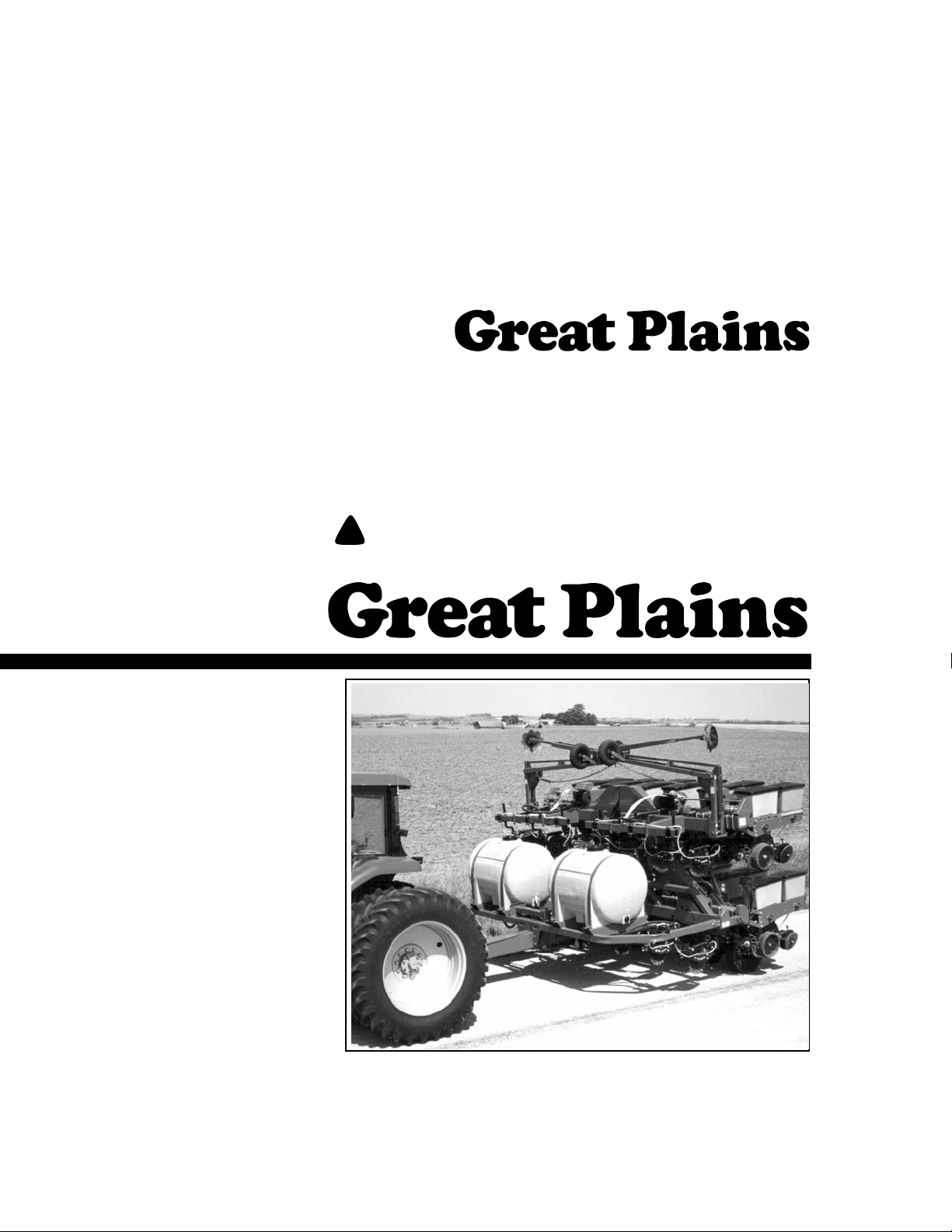
Predelivery Instructions
PT1230
Folding Pull-Type Planter
Manufacturing, Inc.
P.O. Box 5060 ● Salina, Kansas 67402-5060
Read this manual entirely . When y ou see this symbol, the subsequent instructions and
!
warnings are serious - follow without exception. Your life and the lives of others depend
on it!
© Copyright 1999 Printed
10/14/08
15788
Cover illustration may show optional equipment not supplied with standard unit.
401-072M
Page 2

Table of Contents
Table of Contents
Important Safety Information . . . . . . . . . . . . . . . . . 1
Safety Notations . . . . . . . . . . . . . . . . . . . . . . . . . 1
Safety Rules . . . . . . . . . . . . . . . . . . . . . . . . . . . . 1
Introduction . . . . . . . . . . . . . . . . . . . . . . . . . . . . . . . 2
Description of Unit. . . . . . . . . . . . . . . . . . . . . . . . 2
Intended Usage. . . . . . . . . . . . . . . . . . . . . . . 2
Using This Manual. . . . . . . . . . . . . . . . . . . . . . . . 2
Definitions . . . . . . . . . . . . . . . . . . . . . . . . . . . 2
Assembly and Setup Assistance. . . . . . . . . . . . . 2
Section 1 Assembly. . . . . . . . . . . . . . . . . . . . . . . . . 3
Tools Required. . . . . . . . . . . . . . . . . . . . . . . . . . . 3
Pre-Assembly Checklist. . . . . . . . . . . . . . . . . . . . 3
Planter Assembly. . . . . . . . . . . . . . . . . . . . . . . . . 3
Row Unit Assembly. . . . . . . . . . . . . . . . . . . . 4
Marker Installation. . . . . . . . . . . . . . . . . . . . . 4
U-Joint Assembly . . . . . . . . . . . . . . . . . . . . . 6
Point Row Clutch. . . . . . . . . . . . . . . . . . . . . . 6
Liquid Fertilizer Assembly . . . . . . . . . . . . . . . . . . 7
Section 2 Setup . . . . . . . . . . . . . . . . . . . . . . . . . . . 10
Hitching Planter to Tractor . . . . . . . . . . . . . . . . . 10
Hydraulic Hose Hookup. . . . . . . . . . . . . . . . . . . 10
Row Unit Setup and Adjustment . . . . . . . . . . . . 11
Appendix. . . . . . . . . . . . . . . . . . . . . . . . . . . . . . . . . 12
Tire Inflation Chart. . . . . . . . . . . . . . . . . . . . . . . 12
Torque Values Chart for Common Bolt Sizes . . 12
Great Plains Mfg., Inc.
© Copyright 1999 All rights Reserved
Great Plains Manufacturing, Inc. provides this publication “as is” without warr anty of any kind, either expressed or implied. W hile ev ery precaution has been taken in the preparation
of this manual, Great Plains Manufacturing, Inc. assumes no responsibility for errors or omissions . Neither is any liability assumed for damages resulting from the use of the inf ormation contained herein. Great Plains Manufacturing, Inc. reserves the right to revise and improve its products as it sees fit. This publication describes the state of this product at the
time of its publication, and may not reflect the product in the future.
The following are trademarks of Great Plains Mfg., Inc.: Application Systems, A usherman, Land Pride, Great Plains
All other brands and product names are trademarks or registered trademarks of their respective holders.
PT1230 Folding Pull-Type Planter 401-072M 10/14/08
Great Plains Manufacturing, Incorporated Trademarks
Printed in the United States of America.
Page 3

Important Safety Information
Important Safety Information
For your safety, thoroughly read “Important Safety Information” and “Operating Instructions” in the operator’s manual
before proceeding.
Safety Notations
The SAFETY ALERT SYMBOL indicates that there is a potential hazard to personal safety involved and extra safety precautions must be taken. When you see this symbol, be alert and
carefully read the message that follows it. In addition to design
and configuration of equipment, hazard control and accident
prevention are dependent upon the awareness, concern, prudence and proper training of personnel involved in the operation, transport, maintenance and storage of equipment.
Watch for the following safety notations throughout your operator’s manual.
!
DANGER!
Indicates an imminently hazardous situation which, if not
avoided, will result in death or serious injury. This signal word
is limited to the most extreme situations.
!
Great Plains Mfg., Inc.
!
WARNING!
Indicates a potentially hazardous situation which, if not avoided, could result in death or serious injury.
!
CAUTION!
Indicates a potentially hazardous situation which, if not avoided, may result in minor or moder ate injury. It may also be used
to alert against unsafe practices.
Safety Rules
Most accidents are the result of negligence, carelessness or
failure to follow safety precautions. Though your implement is
designed with many built-in safety features, safety precautions
are mandatory to prevent accidents.
PT1230 Folding Pull-Type Planter 401-072M 10/14/08
0
Page 4

Great Plains Mfg., Inc.
Introduction
Introduction
Great Plains Manufacturing wants y ou to be satisfied with
any new machine delivered b y the Great Plains Trucking
network. To ease the assembly task and produce a prop
erly working machine, read this entire manual before assembling or setting up new equipment.
Description of Unit
The 12-row , 30-inch spacing, pull-type planter has six rigid
center rows and 3 rows on each end which float indepen
dently in field operation. The outer 3 rows on each end lift
and fold abov e the center rows for transporting. Field turns
can be completed in a relatively small radius due to the lift
wheels and short tongue.
The PL1230 allows application of liquid fertilizer .The complete system allows you to band liquid fertilizer on 12 rows
with two, 230-gallon liquid tanks and an optional squeeze
pump.
Intended Usage
This machine is intended for planting row crops in conv entional as well as no-till conditions.
Using This Manual
This manual was written to help you assemble and prepare the new machine for the customer. The manual includes instructions for assembly and setup . Read this
manual and follow the recommendations f or safe, efficient
and proper assembly and setup.
An operator’s man ual is also pro vided with the ne w machine. Read and understand “Important Safety Informa-
tion” and “Operating Instructions” in the operator’ s
manual before assembling the machine . As a reference,
keep the operator’ s man ual on hand while assembling.
The information in this manual is current at printing. Some
parts may change to assure top performance.
-
Definitions
The following terms are used throughout this manual.
Right and left as used in this manual are determined by
facing the direction the machine will trav el while in use un
less otherwise stated.
NOTE: Useful inf ormation about the preceding topic.
IMPORTANT: A crucial point of information about the
preceding topic. For safe and correct oper ation, read
and follow the directions provided before continuing.
Assembly and Setup Assistance
To order additional copies of predelivery instructions or
operator’s and parts manuals, write to the follo wing ad
dress. Include model numbers in all correspondence.
If you do not understand any part of this manual or have
other assembly or setup questions, assistance is av ail
able. Contact
Product Support
Great Plains Mfg. Inc., Service Department
P.O . Box 5060
Salina, KS 67402-5060
-
-
-
10/14/08
PT1230 Folding Pull-Type Planter 401-072M
1
Page 5
Section 1 Assembly
Section 1 Assembly
Great Plains Mfg., Inc.
The following headings are step-by-step instructions for
assembling the planter. Begin with Tools Required and
Pre-Assembly Checklist to make sure y ou ha v e all neces
sary parts and equipment. Then proceed with Planter As-
sembly. Follow each step to make the job as quick and
safe as possible and produce a properly working machine.
The planter is shipped via flat bed truck. It is the dealer’s
responsibility to unload the new machine. Unload all
equipment before beginning assembly . Do not attempt any
assembly work while the planter is on the truck.
Tools Required
• Forklift with 3,000 pound capacity
• Lifting chains
• General hand tools
Pre-Assembly Checklist
1. Read and understand “Important Safety Information” on page 0 before assemb ling.
2. Have at least two people on hand while assemb ling.
3. Make sure the assembly area is le vel and free of obstructions (preferably an open concrete area).
4. Have all major components.
5. Have all f asteners and pins shipped with the planter
Planter Assembly
-
.
!
WARNING!
The fertilizer-tank weldment weighs more than 300 pounds and
could cause serious injury if it falls. Make sure the weldment is
securely attached to an adequate lifting device. Keep people
away while the weldment is being lifted. Do not place any body
parts under the weldment at any time.
1. If the planter has liquid fertilizer, remo ve fertilizer-tank
weldment from the planter frame. Secure adequate
lifting device to the weldment. Unstrap the weldment
from the planter frame. Loosen and remove the bolts
that hold the weldment on the planter. Sa ve bolts,
washers and nuts. Lift the weldment off the planter
frame and lower weldment to the ground.
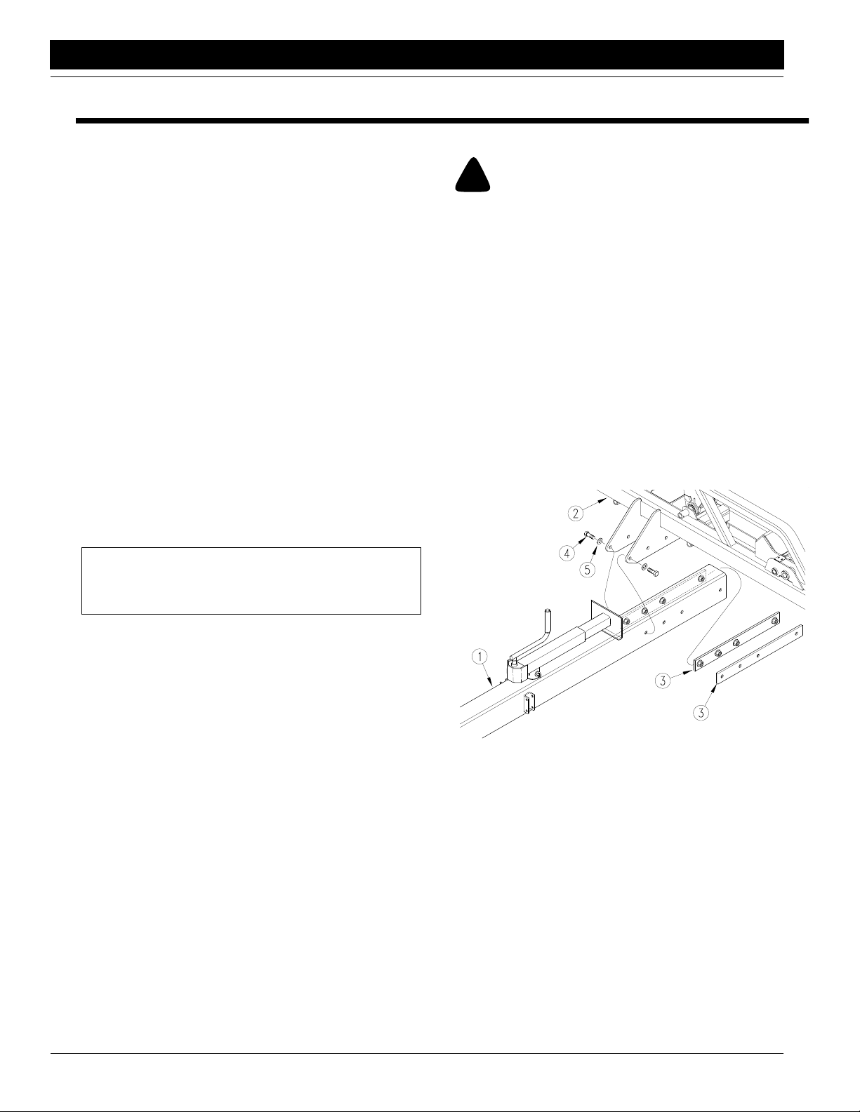
2. Refer to Figure 1-1. Attach tongue assembly (1) to
frame assembly (2) by installing nut str aps (3) with 1by-2 1/2-inch hex bolts (4) and USS flat washers (5).
Install front bolts first. T orque bolts as listed on Torque
V alues Chart, “Appendix,”
page 11.
IMPORTANT: If a pre-assembled part or fastener is
temporarily removed, remember where it goes. Keep
the parts separated.
6. Have a cop y of the parts manual on hand. If unsure of
proper placement or use of any part or fastener, ref er
to the parts manual.
7. Check that all working parts are moving freely, bolts
are tight, and cotter pins are spread.
8. Check for proper tension and alignment on all drive
chains.
9. Check that all safety labels and reflectors are correctly
located and legible. Replace if improperly located or
damaged. Refer to Safety Labels , “Important Safety
Information” in the operator’ s man ual.
10. Inflate tires to recommended pressure as listed on the
Tire Inflation Chart on the “Appendix” on
Tighten wheel bolts as specified on Torque Values
Chart on the “Appendix” on
page 11.
page 11.
15898
Figure 1-1
Tongue and Frame Assembly
PT1230 Folding Pull-Type Planter 401-072M 10/14/08
2
Page 6

Great Plains Mfg., Inc.
Section 1 Assembly
3. Pull hoses and electrical wires through tongue by
pushing a wire in through the hole near the valve
mounting (see
Figure 1-2) and pulling the hoses and
selector through the tongue.
4. Refer to Figure 1-2. Attach selector valv e (1) to mounting bracket on tongue with 5/16-b y-3/4-inch hex flange
cap screws (2).
15899
Figure 1-2
Selector Valve Mounting
5. Hitch tractor to planter. Refer to Hitching Planter to
Tractor, “Setup,”
page 9.
6. Connect hydraulic hoses. See Hydraulic Hose Hook-
up, “Setup,” page 9.
7. Remove the seed and chemical hoppers on rows f our
and nine to prevent damage to hoppers .
8. Unfold the planter as explained in the oper ator’ s manual. Be certain wing arms are locked and cylinder
stops are installed.
9. Install slow-moving vehicle sign as sho wn in Figure 1-
3. Bolt sign (1) to bracket (2) and slide bracket into
keeper on frame (3).
Row Unit Assembly
Refer to Figure 1-4.
1. Disassemble row-unit springs (1) from mounting shaft
(2) by removing cotter pins and washers.
2. Hook springs into row-unit mount (3).
3. T urn ey e-bolts (4) so they are just below the mounting
shaft (2), then turn eye-bolts back just enough so you
can assemble eye-bolts on mounting shaft (2).
4. Secure springs to mounting shaft using washers and
cotter pins
.
16878
Figure 1-3
Slow Moving Vehicle Sign Installation
10/14/08
17790
Figure 1-4
Row Unit Assembly
Marker Installation
Before assembling markers , hitch the planter to the tractor
and hookup the planter hydraulic hoses. Ref er to “Setup,”
page 9 and “Planter Operation” in the operator’s man ual.
Have ample space to assemble and install mark ers. Overall width with the markers unfolded is 60 feet.
PT1230 Folding Pull-Type Planter 401-072M
3
Page 7

Section 1 Assembly
Great Plains Mfg., Inc.
Refer to Figure 1-5.
1. Lower planter into planting position.
2. Attach first-stage arm (1) to marker mount (2) using
the 1-by-9-inch pin (3) and roll pin.
3. Move h ydraulic selector valve to field position and extend marker cylinder 6 inches.
4. Attach marker cylinder (4) to first-stage arm using a
cylinder pivot pin (5) and cotter pin.
Refer to Figure 1-7.
8. Assemble the third stage arm (1) to the second stage
pivot (2) using a 1-by-9-inch pin (3) and roll pin (4). As
semble marker so shear protection (5) faces the direction of marker travel
Third Stage Arm to Second Stage Arm
.
15902
Figure 1-7
-
15900
Figure 1-5
First Stage Arm to Marker Mount
5. Start tractor and fully extend cylinder. Shut off tractor.
Refer to Figure 1-6.
6. Connect second stage arm (1) to first stage arm (2)
with a 1-by-9-inch pin (3) and roll pin (4).
7. Attach the transfer link (5) to the second-stage arm
using a pivot pin (6) and cotter pin (7).
Refer to Figure 1-8.
9. Attach the link control (1) to the first-stage arm (2) using 1/2-by-1 1/2-inch carriage bolts (3), 13/16-inch
bushings (4) and flange lock nuts (5). Attach the link
control to the second-stage arm (6) with a 1/2-by-2inch bolt (7), 13/16-inch bushing and flange lock nut
(5).
10. Attach the other end of the link control to the thirdstage arm (8) using a 1/2-by-2 1/4-inch bolt (9), a
13/16-inch bushing and flange lock nut.
15901
Figure 1-6
Second Stage Arm to First Stage Arm
PT1230 Folding Pull-Type Planter 401-072M 10/14/08
4
15904
Figure 1-8
Link Control Assembly
Page 8

Great Plains Mfg., Inc.
Section 1 Assembly
11. Mount marker gauge wheel on second-stage arm
near the joint with the third-stage arm. U-bolt the
wheel to the front marker tube as shown.
IMPORTANT: Mount the marker gauge wheel so it is
square with the ground–not square with the marker
tube.
!
DANGER!
Never allow anyone near the planter when cycling the markers.
Excessive travel speed of the markers can be danger ous and/or
damage the marker assembly.The flow controls should be prop
erly adjusted before the marker assembly is first put into use.
Refer to Figure 1-11.
16. Adjust marker speed. The markers have needle
valves in the body of the sequence v alves to control
how fast each marker operates . There are two adjust
ment heads–one for controlling marker speed up and
one for controlling marker speed down.
With oil warm and the tractor engine at an operating
speed, adjust the needle valve to limit the marker to a
safe operating speed. T o adjust, loosen jam n ut, screw
the needle valve cloc kwise to a low setting. Excessive
folding speeds can cause marker damage.
-
-
Figure 1-9
Mount Marker Gauge Wheel
12. Lubricate all grease points.
13. Adjust width marker. Measure 30 f eet from the center
line of the planter to the marker blade.
14. Slowly fold markers and observe the link control (1).
When properly adjusted, the link will have the angle
shown in
link is improperly adjusted, the third-stage arm will not
rest on the marker stop or the folded markers will not
clear each other when the planter is folded.
15. If necessary, adjust the link. To adjust, remo ve the
connecting pin (see
bolt to shorten or lengthen the link.
Figure 1-10. The link should not sag. If the
1
Figure 1-10
Link Control Properly Adjusted
Figure 1-8, 9) and turn the eye
16879
15780
Figure 1-11
Flow Control Raise and Lower
IMPORT ANT : JIC fittings do not require high torque.
JIC and O-Ring fittings do not require sealant. To
avoid possible danger of cracking hydraulic fittings
from over tightening, do not use plastic sealant
tape.
17. Fold the marker up and down a f ew times and recheck
for pinching and kinking of hoses.
U-Joint Assembly
Connect drive shaft by removing keeper pin on one end of
the drive shaft. Slide drive shaft together and reinstall
keeper pin.
Point Row Clutch
Refer to operator’ s manual to install the control bo x for the
point row clutches.
15029
10/14/08
PT1230 Folding Pull-Type Planter 401-072M
5
Page 9

Section 1 Assembly
Great Plains Mfg., Inc.
Liquid Fertilizer Assembly
!
WARNING!
The fertilizer-tank weldment weighs more than 300 pounds and
could cause serious injury if it falls. Make sure the weldment is
securely attached to an adequate lifting device. Keep people
away while the weldment is being lifted. Do not place any body
parts under the weldment at any time.
1. Unstrap the fertilizer bars (1) from the fertilizer-tank
weldment (2).
16774
Figure 1-12
Remove Fertilizer Bars
2. Install fertilizer-tank weldment (1). Use forklift or other
mechanical lifting device to position the weldment
over the planter tongue. Use 5/8-b y-1 3/4-inch bolts ,
flat washers and flange nuts to bolt the weldment on
the frame tube (2) and tongue (3).
3. Install coulter bars (1) on the wing sections. Bolt the
extension brack ets (2) to the front fr ame tube using
5/8-by-7 1/32-inch u-bolts (3) and flange nuts (4). Bolt
the coulter bars to the extension brack ets using 5/8by-4 1/32-inch u-bolts (5) and flange nuts (4).
15908
Figure 1-14
Install Fertilizer Bars
4. Mount coulters on coulter bar. Ref er to your coulter
manual for specific instructions to achiev e your tillage
and fertilizer-application objectives.
5. Mount the left-hand squeeze pump (1) on the lefthand wing section. Mount the pump on the rear frame
tube just inside of the contact-drive tower (2). Mount
the pump ahead of the row unit (3) as shown in illus
tration. Use two 5/8-by-7 1/32-inch u-bolts and flange
nuts to secure pump.
6. Couple transmission shaft (4) to contact-drive shaft
with coupler sleeve (5). Secure slee ve to transmission
shaft with cotter key.
7. Repeat steps for the right-hand pump on the righthand wing section.
-
16771
Figure 1-13
Install Fertilizer Tank Weldment
PT1230 Folding Pull-Type Planter 401-072M 10/14/08
6
16770
Figure 1-15
Install Squeeze Pumps
Page 10

Great Plains Mfg., Inc.
Section 1 Assembly
8. Mount tanks. Unstrap the tanks from the shipping pallet. Use two people to position each tank (1) on the
weldment (2). Position each tank so the dr ain plug (3)
is toward the inside. Strap tanks to weldment using
tank straps (4) and 1/2-by-4-inch bolts (5).
16772
Figure 1-16
Install Tanks
9. Plumb tanks. Assemble fittings as shown in Figure 1-
17.
From the roll of 1 1/2-inch hose, cut hoses to connect
fittings. As a guide, use the approximate hose lengths
(in inches) on the illustration. Hose lengths will vary
from unit to unit.
Route hoses through holders (1) on fertilizer tank
weldment. Use worm clamps to secure hoses on fit
tings.
1
1
16898
Figure 1-18
Tanks Plumbed
10. Plumb squeeze pumps.
a. From the roll of 1-inch hose cut two hoses that are
each about 13 feet 6 inches long. Check the dis
tance between the T-fitting (1) and squeeze
pumps on your planter before cutting hose.
b. Route hoses over planter frame as shown in illus -
tration. Route hoses through wing housings (2)
when planter is folded.
c. Use hose clamps (3) to secure fertilizer hoses to
the planter frame in six location–four on the center
section and one on each wing. Use hose ties to
bundle the hoses together and to the planter
frame. Assemble clamps as shown in insert.
-
-
10/14/08
79 1/2
15
15
Figure 1-17
Plumb Tanks
58
16777
16897
Figure 1-19
T-Fitting to Squeeze Pump
PT1230 Folding Pull-Type Planter 401-072M
7
Page 11

Section 1 Assembly
d. Use worm clamps to secure hose to the squeeze
pump inlet (1) and T-fitting.
1
16894
Figure 1-20
Squeeze Pumps Plumped
11. Plumb coulters. F rom the roll of 3/8-inch hose cut hoses to connect squeeze pumps and coulters. Hose
lengths will vary with coulter positioning. Use hose
ties (1) to secure hoses to coulter arms.
Great Plains Mfg., Inc.
1
1
Figure 1-21
Plumb Coulters
1
12. Use worm clamps to secure 3/8-inch hoses to
squeeze-pump outlets. Use hose ties to secure hoses
to planter frame. Make sure hoses will not be pinched
or snagged during planter operation.
16890
PT1230 Folding Pull-Type Planter 401-072M 10/14/08
8
Page 12

Great Plains Mfg., Inc.
Section 2 Setup
Hitching the Planter to Tractor
!
DANGER!
Y ou may be se ver ely injur ed or killed by being crushed between
the tractor and planter. Do not stand or place any part of your
body between planter and moving tractor. Stop tractor engine
and set park brake before installing pins.
When hitching to the tractor, use the jac k as shown in Figure 2-1 to raise and lower the planter.
When hitching the planter to the tractor, alw ays secure the
safety chain to an anchor on the tractor capable of pulling
the planter.
15817
Figure 2-1
Jack Stand in Parking Position
After hitching the planter and tractor, store the jac k on the
stob on top the tongue as shown in
Figure 2-2.
15818
Figure 2-2
Jack in Storage Position
Hydraulic Hose Hookup
Great Plains hydraulic hoses are color coded to help you
hookup hoses to your tractor outlets. Hoses that go to the
same remote valve are marked with the same color.
Color Hydraulic Function
White Fold/Marker Cylinders
Blue Lift Cylinders
T o distinguish hoses on the same h ydraulic circuit, ref er to
plastic hose holder. See
cylinder symbol feeds cylinder base ends and raises the
planter. Hose under retracted-cylinder symbol f eeds cylin
der rod ends and lowers planter .
Figure 2-3. Hose under extended-
-
10/14/08
17641
Figure 2-3
Hydraulic Hose Label
PT1230 Folding Pull-Type Planter 401-072M
9
Page 13

Row Unit Setup and Adjustment
The meter clutch and meter-input shaft must be aligned.
Misalignment will cause meter malfunction and excessive
meter-housing wear. Periodically check vertical and hori
zontal alignment of meter clutch and meter-input shaft.
Refer to Figure 2-4.
1. Latch hopper onto hopper support.
2. Check that roll pin (1) in end of the meter-input shaft is
centered. When centered, equal amounts of the roll
pin will protrude from both sides of the shaft.
3. Rotate meter-input shaft so that roll pin is vertical.
4. Rotate the drive coupler (2) on meter clutch so that the
slots are vertical.
5. Release meter clutch to engage meter-input shaft.
6. If shafts are aligned vertically , the drive coupler will en-
gage with meter-input shaft freely and the roll pin will
extend equally on each side of the drive coupler. Dis
engage the clutch and repeat steps, checking for horizontal alignment.
Great Plains Mfg., Inc.
-
-
17891
Figure 2-4
Vertical Alignment
7. If drive coupler does not freely engage meter-input
shaft vertically or horizontally, loosen 5/16-inch nuts
(3) shown in
Figure 2-4. Engage meter clutch. Align
meter clutch with meter-input shaft.
8. Tighten 5/16-inch nuts to torque values listed on
Torque Values Chart, “Appendix,”
PT1230 Folding Pull-Type Planter 401-072M 10/14/08
10
page 11.
Page 14

Great Plains Mfg., Inc.
Appendix
Appendix
Torque Values Chart for Common Bolt Sizes
Bolt Head Identification
Bolt Size
(Inches)
1
in-tpi
1/4" - 20 7.4 5.6 11 8 16 12 M 5 X 0.8 4 3 6 5 9 7
1/4" - 28 8.5 6 13 10 18 14 M 6 X 1 7 5 11 8 15 11
5/16 - 18 15 11 24 17 33 25 M 8 X 1.25 17 12 26 19 36 27
5/16" - 24 17 13 26 19 37 27 M 8 X 1 18 13 28 21 39 29
3/8" - 16 27 20 42 31 59 44 M10 X 1.5 33 24 52 39 72 53
3/8" - 24 31 22 47 35 67 49 M10 X 0.75 39 29 61 45 85 62
7/16" - 14 43 32 67 49 95 70 M12 X 1.75 58 42 91 67 125 93
7/16" - 20 49 36 75 55 105 78 M12 X 1.5 60 44 95 70 130 97
1/2" - 13 66 49 105 76 145 105 M12 X 1 90 66 105 77 145 105
1/2" - 20 75 55 115 85 165 120 M14 X 2 92 68 145 105 200 150
9/16" - 12 95 70 150 110 210 155 M14 X 1.5 99 73 155 115 215 160
9/16" - 18 105 79 165 120 235 170 M16 X 2 145 105 225 165 315 230
5/8" - 11 130 97 205 150 285 210 M16 X 1.5 155 115 240 180 335 245
5/8" - 18 150 110 230 170 325 240 M18 X 2.5 195 145 310 230 405 300
3/4" - 10 235 170 360 265 510 375 M18 X 1.5 220 165 350 260 485 355
3/4" - 16 260 190 405 295 570 420 M20 X 2.5 280 205 440 325 610 450
7/8" - 9 225 165 585 430 820 605 M20 X 1.5 310 230 650 480 900 665
7/8" - 14 250 185 640 475 905 670 M24 X 3 480 355 760 560 1050 780
1" - 8 340 250 875 645 1230 910 M24 X 2 525 390 830 610 1150 845
1" - 12 370 275 955 705 1350 995 M30 X 3.5 960 705 1510 1120 2100 1550
1-1/8" - 7 480 355 1080 795 1750 1290 M30 X 2 1060 785 1680 1240 2320 1710
1 1/8" - 12 540 395 1210 890 1960 1440 M36 X 3.5 1730 1270 2650 1950 3660 2700
1 1/4" - 7 680 500 1520 1120 2460 1820 M36 X 2 1880 1380 2960 2190 4100 3220
1 1/4" - 12 750 555 1680 1240 2730 2010
1 3/8" - 6 890 655 1990 1470 3230 2380
1 3/8" - 12 1010 745 2270 1670 3680 2710
1 1/2" - 6 1180 870 2640 1950 4290 3160
1 1/2" - 12 1330 980 2970 2190 4820 3560
Torque tolerance + 0%, -15% of torquing values. Unless otherwise specified use torque values listed above.
Grade 2 Grade 5
N · m2ft-lb3N · m ft-lb N · m ft-lb mm x pitch
Grade 8
Bolt Size
(Metric)
4
N · m ft-lb N · m ft-lb N · m ft-lb
1
in-tpi = nominal thread dia.in inches-threads per inch
2
N· m = newton-meters
3
ft-lb= foot pounds
4
mm x pitch = nominal thread dia. in millimeters x thread pitch
Bolt Head Identification
5.8 8.8 10.9
Class 5.8 Class 8.8 Class 10.9
Tire Inflation Chart
Tire Size Inflation PSI Tire Size Inflation PSI
7.50 x 20" 4-Ply Rib 28 11L x 15" 6-Ply Rib Implement 28
9.0 x 22.5 10-Ply Highway Service 70 70 11L x 15" 12-Ply Rib Implement 52
9.0 x 24" 8-Ply Rib Implement 40 12.5L x 15" 8-Ply Rib Implement 36
9.5L x 15" 6-Ply Rib Implement 32 12.5L x 15" 10-Ply Rib Implement 44
9.5L x 15" 8-Ply Rib Implement 44 16.5L x 16.1" 10-Ply Rib Implement 36
9.5L x 15" 12-Ply Rib Implement 60 21.5 x 16.1” SC 10-Ply Rib Implement 28
10/14/08
PT1230 Folding Pull-Type Planter 401-072M
11
Page 15

Great Plains Manufacturing, Inc.
Corporate Office: PO. Box 5060
Salina, Kansas 67402-5060 USA
 Loading...