

Press Wheel Mount Update Kit
25 and 25AP Series Implements
General Information
These instructions explain how to install a Press Wheel
Mount Update Kit. One kit updates one opener.
These instructions apply to an installation of:
Kit Kit Description
199-146A 25P LONG PW MOUNT KIT
199-147A 25P MID PW MOUNT KIT
Related Documents
Also available as a reference see the Parts Manual for
the particular implement being updated.
118-231P 2025 & 2525P (2007+)
118-232P 2025F & 2525F 3PT
118-949P 1525P
118-999P 2025A & 2525A
196-286P 3N-4025P
401-226P YP1225/1625
401-312P 3PYP
401-406P YP2425
401-571P YP40
401-625P YP1225A/1625A
401-626P YP2425A
401-627P YP4025A
401-651P YP425A/625A/825A
401-652P YP425A/625A/825A 3PT
401-647P 3PYPA
Part Lists Great Plains Manufacturing, Inc. 1
When you see this symbol, the subsequent instructions
and warnings are serious - follow without exception.
Your life and the lives of others depend on it!
U
F
L
R
B
D
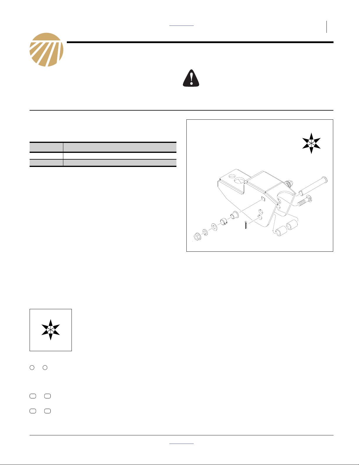
Figure 1
Press Wheel Mount Kit
31489
Notations and Conventions
U
F
L
D
Call-Outs
1 9
to
11
to
51 64
to
© Copyright 2010 Printed 08/19/2010 Part Lists 199-146M
Single-digit callouts identify components in
the currently referenced Figure. These numbers may be reused for different items from
page to page.
22
Two-digit callouts in the range 11 to 22 reference new parts from the list on page 5.
Two-digit callouts in the range 51 to 64 reference existing parts from the list on page 5.
“Left” and “Right” are facing in the
direction of machine travel. An orienta-
R
tion rose in the line art illustrations
shows the directions of Left, Right,
Front, Back, Up, Down.
B
2 Great Plains Manufacturing, Inc. Front Page Part Lists Press Wheel Mount Update
Pre-Assembly Preparation
Tools Required
• suitable tractor for raising implement
• basic hand tools
• dead blow hammer or press
Work Location
1. Move the implement to a location with:
• flat, smooth surface
• adequate illumination
• clear surface beneath for recovery of any falling or
dropped parts
Prepare Implement
2. Raise implement with tractor.
3. Secure for safety.
Crushing and Sharp Object Hazards:
Be careful working near openers. Discs and other parts may
be sharp.
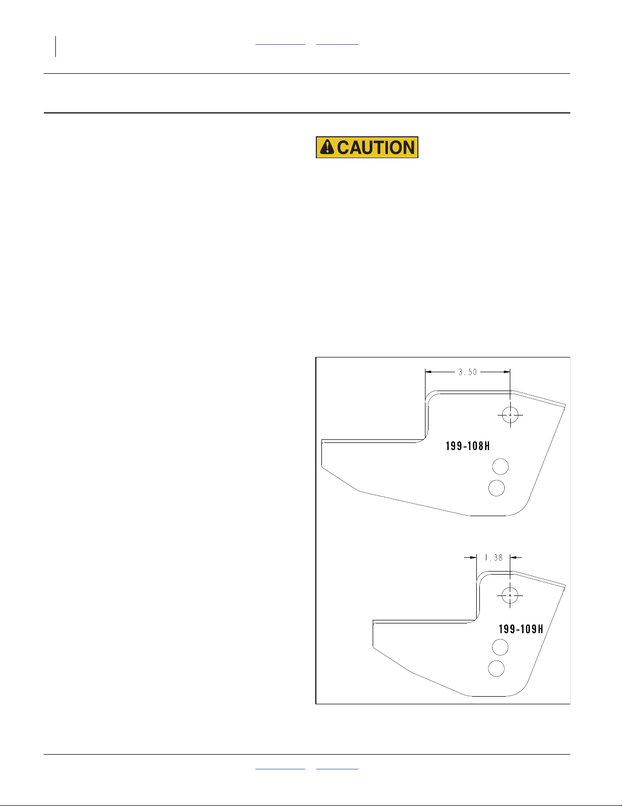
How to Identify Mount Length
To avoid confusion, if implement uses a combination of
both long and short press wheel mounts it may be easier
to remove and replace all the longs then all the shorts or
change out one complete arm at a time.
199-108H 25P LONG PW MOUNT
199-109H 25P MID PW MOUNT
Figure 2
Press Wheel Mount Lengths
199-146M Front Page Part Lists 08/19/2010
31507

Remove Old PW Mount Front Page Part Lists Great Plains Manufacturing, Inc. 3
Remove Old PW Mount
Refer to Figure 3
With openers slightly off ground spring tension is
released.
4. To detach press wheel assembly from opener
2
body remove two vertical bolts, washers, and nuts
from underside of press wheel mount:
56
802-091C HHCS 1/2-13X1 1/2 GR5
57
802-258C HHCS 1/2-13X1 GR5
61
804-015C WASHER LOCK SPRING 1/2 PLT
55
405-032D 1X12 PW ADJUSTER
64
51
2
52
63
53
58
54
Save hardware for reuse.
5. Detach old press wheel mount and/or from
press wheel arm by removing bolt, bushings, pin
clevis and other hardware.
58
802-616C HHCS 3/8-16X5 1/2 GR5
60
804-011C WASHER FLAT 3/8 USS PLT
59
803-209C NUT FLANGE LOCK 3/8-16 PLT
51
199-106D PW ANCHOR MOUNT TUBE
54
199-113D SPRING ALIGNMENT BUSHING
63
805-417C PIN CLEVIS 5/8 X 3 49/64 USBL
62
805-109C PIN COTTER 1/8 X 1 1/4 PLT
64
817-083C PW ARM PIVOT BUSHING
This hardware is not reused
6. Discard press wheel mount (it will not be reused):
Note: The opener assemblies can have all long or all
short mounts or a combination of the two.
52
199-108H 25P LONG PW MOUNT
53
199-109H 25P MID PW MOUNT
1
52 53
55
61
56
62
61
57
Figure 3
Remove PW Mount
59
60
60
1
31490
08/19/2010 Front Page Part Lists 199-146M

4 Great Plains Manufacturing, Inc. Front Page Part Lists Press Wheel Mount Update
Install New PW Mount
Refer to Figure 4
7. With press or dead blow hammer insert one bushing
12
16
2
13
14
17
Figure 4
21
18
22
20
15
18
16
3
17
1
31494
22 3 1
in hole on each side of the press wheel arm .
Install one pivot spacer into each bushing.
22
890-598C BUSHING 3/4OD X 5/8ID X 1/2
21
890-524C 20 SER PW ARM PIVOT SPACER
8. Select one new press wheel mount or :
Note: The press wheel assemblies can have either
all long or all short mounts or a combination of the
two.
13
199-148H 25P LONG PW MOUNT UPDATE
14
199-149H 25P MID PW MOUNT UPDATE
9. Slide new press wheel mount or into press
wheel arm . Insert 2 new carriage bolts in press
wheel mount (make sure head is on inside of pw
mount with end facing to the outside).
15
802-030C RHSNB 7/16-14X1 3/4 GR5
Select one each and install on end of each bolt:
18
804-041C WASHER FLAT 7/16 SAE PLT
17
804-014C WASHER LOCK 7/16 PLT
16
803-229C NUT HEX FLANGE LOC 7/16-14
10. Attach the spring on the underside of the press
wheel arm and insert top ring of spring between
the 2 spring alignment bushings .
115
1
21
13 14
13 14
12
22
21
55
61
19
56
57
Install New PW Mount Kit
Attach the spring to the lower holes of the mount
with the clevis pin and spacer bushings .
Secure with cotter pin .
12
199-113D SPRING ALIGNMENT BUSHING
20
805-417C PIN CLEVIS 5/8 X 3 49/64 USBL
19
805-109C PIN COTTER 1/8 X 1 1/4 PLT
11. Reinstall press wheel assembly to opener body
reusing hardware from prior disassembling.
56
802-091C HHCS 1/2-13X1 1/2 GR5
57
802-258C HHCS 1/2-13X1 GR5
61
804-015C WASHER LOCK SPRING 1/2 PLT
55
405-032D 1X12 PW ADJUSTER
20 12
19
13
2
199-146M Front Page Part Lists 08/19/2010

Appendix Front Page Part Lists Great Plains Manufacturing, Inc. 5
Appendix
Part Lists
New Parts
The part call-out numbers in this list match all Figures in
these installation instructions. Part descriptions match
those in your updated Parts Manual.
Quantities are units (“ea”).
Kit Contents
199-146A 25P LONG PW MOUNT KIT
199-147A 25P MID PW MOUNT KIT
Quantity in Kit:
Callout 199-146A 199-147A Part Number Part Description
11 1 1 199-146M MANUAL PW MOUNT KIT UPDATE
12 2 2 199-113D SPRING ALIGNMENT BUSHING
13 1 0 199-148H 25P LONG PW MOUNT UPDATE
14 0 1 199-149H 25P MID PW MOUNT UPDATE
15 2 2 802-030C RHSNB 7/16-14X1 3/4 GR5
16 2 2 803-229C NUT HEX FLANGE LOC 7/16-14
17 2 2 804-014C WASHER LOCK 7/16 PLT
18 2 2 804-041C WASHER FLAT 7/16 SAE PLT
19 1 1 805-067C PIN COTTER 1/8 X 3/4
20 1 1 805-417C PIN CLEVIS 5/8 X 3 49/64 US
21 2 2 890-524C 20 SER PW ARM PIVOT SPACER
22 2 2 890-598C BUSHING 3/4OD X 5/8ID X 1/2
Existing Parts Affected
The following existing parts are involved in the kit installation. The Disposition column indicates whether the part
is left in place, moved or not re-used.
The part call-out numbers in the list matches all Figures
in the installation instructions. The descriptions match
those in your implement Parts manual.
Callout Part No. Part Description Part Disposition
51 199-106D PW ANCHOR MOUNT TUBE Removed. Not reused.
52 199-108H 25P LONG PW MOUNT Removed. Not reused.
53 199-109H 25P MID PW MOUNT Removed. Not reused.
54 199-113D SPRING ALIGNMENT BUSHING Remove. Not reused.
55 405-032D 1X12 PW ADJUSTER Removed and re-installed.
56 802-091C HHCS 1/2-13X1 1/2 GR5 Removed and re-installed.
57 802-258C HHCS 1/2-13X1 GR5 Removed and re-installed.
58 802-616C HHCS 3/8-16X5 1/2 GR5 Removed. Not reused.
59 803-209C NUT FLANGE LOCK 3/8-16 PLT Removed. Not reused.
60 804-011C WASHER FLAT 3/8 USS PLT Removed. Not reused.
61 804-015C WASHER LOCK SPRING 1/2 PLT Removed and re-installed.
62 805-109C PIN COTTER 1/8 X 1 1/4 PLT Removed. Not reused.
63 805-417C PIN CLEVIS 5/8 X 3 49/64 USBL Removed. Not reused.
64 817-083C PW ARM PIVOT BUSHING Removed. Not reused.
08/19/2010 Front Page Part Lists 199-146M

6 Front Page Part Lists
Abbreviations
3PT 3 Point PW Press Wheel
A Air-Pro RHSNB Round Head Shank Neck Bolt
F Fluted SAE Society of Automotive Engineers
GR5 Grade 5 SER Series
HHCS Hex Head Cap Screw W/ With
OD Outside Diameter X By
PLT Plated
Great Plains Manufacturing, Inc.
Corporate Office P.O. Box 5060
Salina, Kansas 67402-5060 USA
199-146M Front Page Part Lists 08/19/2010
 Loading...