

Page 1
Page 2

Page 3

TABLE OF CONTENTS
Safety Notices ...................................................................................................... 1
Introduction .......................................................................................................... 3
System Overview ............................................................................................................... 3
Specifications..................................................................................................................... 5
Major Features ..................................................................................................... 7
Performance ...................................................................................................................... 7
Console/Display ................................................................................................................. 7
Compatibility ...................................................................................................................... 7
User Aid ............................................................................................................................. 7
Quick Start Guide................................................................................................. 9
Planter Configuration ......................................................................................................... 9
Number of Rows ............................................................................................................................... 9
Row Spacing ................................................................................................................................... 10
Ground Speed Configuration ........................................................................................... 11
Help Card......................................................................................................................... 12
Key Functions .................................................................................................... 15
On/Off Key ....................................................................................................................... 15
Alarm Cancel Key ............................................................................................................ 15
Enter Key ......................................................................................................................... 16
Escape Key...................................................................................................................... 16
Up and Down Arrow Keys................................................................................................ 16
Left and Right Arrow Keys ............................................................................................... 16
Operate Key..................................................................................................................... 16
Planter Setup Key............................................................................................................ 16
Ground Speed Setup Key ................................................................................................ 17
Limits Setup Key.............................................................................................................. 17
Display And Service Key ................................................................................................. 17
Accessory Setup Key....................................................................................................... 17
Seed Count Mode Key..................................................................................................... 17
Speed Area Mode Key..................................................................................................... 17
Editing Screen Fields Using Keys.................................................................................... 18
Highlighted Digit for Editing............................................................................................................. 18
Installation .......................................................................................................... 19
Standard Mounting Bracket ............................................................................................. 19
Optional Mounting 3D Adjustable Bracket ....................................................................... 20
Installing Console Harnesses .......................................................................................... 21
Installing Implement Harness and Sensors ..................................................................... 22
PM300, PM332, PM400 Planter Monitors
11001-1372-200606
i
Page 4

TABLE OF CONTENTS
Advanced SetUp................................................................................................ 23
Planter and Ground Speed............................................................................................... 23
Row SetUp (Auto Assigned)............................................................................................................ 23
Ground Speed Setup....................................................................................................................... 24
Manual Ground Speed Constant Entry............................................................................................ 25
Accessory Setup (Optional)............................................................................................. 26
Limits Setup (population) (Optional) ................................................................................ 28
Target Population ............................................................................................................................ 28
HI Population/Low Population ......................................................................................................... 29
Population Adjustment..................................................................................................................... 29
Population Response Rate .............................................................................................................. 29
Units of Measurement, Backlighting and Alarm Volume Control..................................... 30
Service Screen ................................................................................................................ 30
Security Screen ............................................................................................................... 31
Auxiliary Modes................................................................................................. 33
Speed Area Mode............................................................................................................ 33
Seed Count Mode............................................................................................................ 33
Monitoring Planting........................................................................................... 35
Operate Screen Setup..................................................................................................... 35
Customizing the Upper Parameter Window .................................................................... 35
Customizing the Lower Parameter Window .................................................................... 37
Available Planting Parameters ........................................................................................ 38
Average Population ......................................................................................................................... 38
Minimum/Average/Maximum Population......................................................................................... 39
Population Row Scan ...................................................................................................................... 39
Average Spacing ............................................................................................................................. 39
Minimum/Average/Maximum Spacing............................................................................................. 39
Spacing Row Scan .......................................................................................................................... 39
Seeds per Distance ......................................................................................................................... 39
Minimum/Average/Maximum Seeds per Distance........................................................................... 39
Seeds per Distance Row Scan........................................................................................................ 39
Field Area 1 ..................................................................................................................................... 40
Field Area 2 ..................................................................................................................................... 40
Total Area ........................................................................................................................................ 40
Speed .............................................................................................................................................. 40
Area per Hour .................................................................................................................................. 40
Fan .................................................................................................................................................. 40
Shaft ................................................................................................................................................ 40
Flow ................................................................................................................................................. 40
Alarms ................................................................................................................ 41
Hopper Level ................................................................................................................... 41
Row Failure ..................................................................................................................... 41
All Rows Failure............................................................................................................... 42
Hi/Low Population Warning ............................................................................................. 43
Fan Speed Low/Hi Limit Warning .................................................................................... 43
Shaft Speed Low/Hi Limit Warning.................................................................................. 44
Flow Low/Hi Limit Warning .............................................................................................. 44
Failed Ground Speed Sensor .......................................................................................... 45
Battery Hi/Low ................................................................................................................. 45
Self-Test Failure .............................................................................................................. 46
Hi Ground Speed Exceeded (Optional) ........................................................................... 46
ii
PM300, PM332, PM400 Planter Monitors
11001-1372-200606
Page 5

TABLE OF CONTENTS
Troubleshooting................................................................................................. 47
Monitor Will Not Power On .............................................................................................. 47
Row Failure or Hi/Low Alarm When Row is Planting Properly..........................................47
Hopper Alarm Does not Sound When Hopper is Empty ...................................................48
Hopper Alarm Does Not Sound When Hopper is Full.......................................................48
System Voltage Alarm ......................................................................................................48
Accessory Alarm Sounds When Shaft, Fan or Flow is Working .......................................49
Ground Speed Alarm Sounds When Forward Movement ................................................49
Ground Speed High Alarm Sounds ..................................................................................49
Self-Test Alarm .................................................................................................................50
Connector Pin-Outs ......................................................................................................... 51
Connector Pin-Outs ......................................................................................................... 52
PM300, PM332, PM400 Planter Monitors
11001-1372-200606
iii
Page 6

TABLE OF CONTENTS
iv
PM300, PM332, PM400 Planter Monitors
11001-1372-200606
Page 7
OPERATOR’S MANUAL
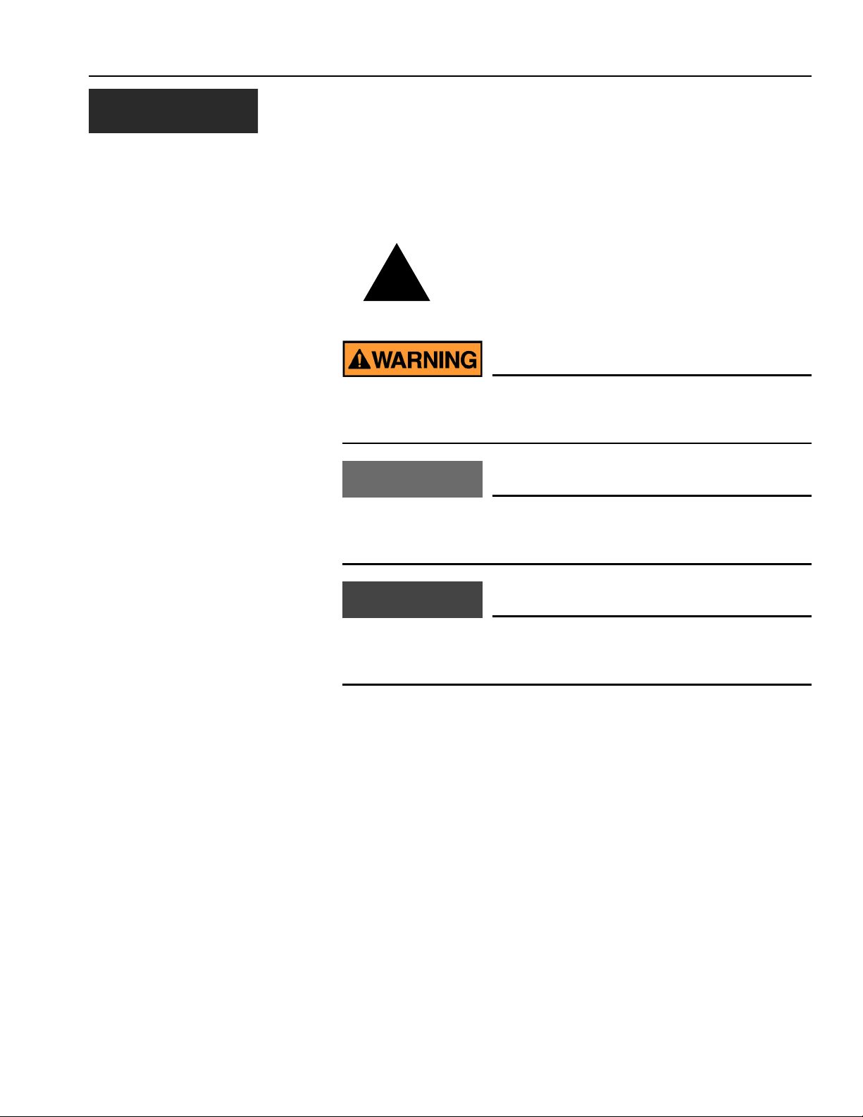
SAFETY NOTICES
Safety notices are one of the primary ways to call attention to potential
hazards.
This Safety Alert Symbol identifies important safety
messages in this manual. When you see this
!
Use of the word WARNING indicates a potentially hazardous
situation which, if not avoided, could result in death or serious
injury.
symbol, carefully read the message that follows. Be
alert to the possibility of personal injury or death.
Use of the word CAUTION with the Safety Alert Symbol indicates a
potentially hazardous situation which, if not avoided, may result in
minor or moderate injury.
Use of the word CAUTION without the safety alert symbol
indicates a potentially hazardous situation which, if not avoided,
may result in equipment damage.
PM300, PM332, PM400 Planter Monitors
11001-1372-200606
SAFETY NOTICES / 1
Page 8

OPERATOR’S MANUAL
2 / SAFETY NOTICES
PM300, PM332, PM400 Planter Monitors
11001-1372-200606
Page 9
OPERATOR’S MANUAL
INTRODUCTION
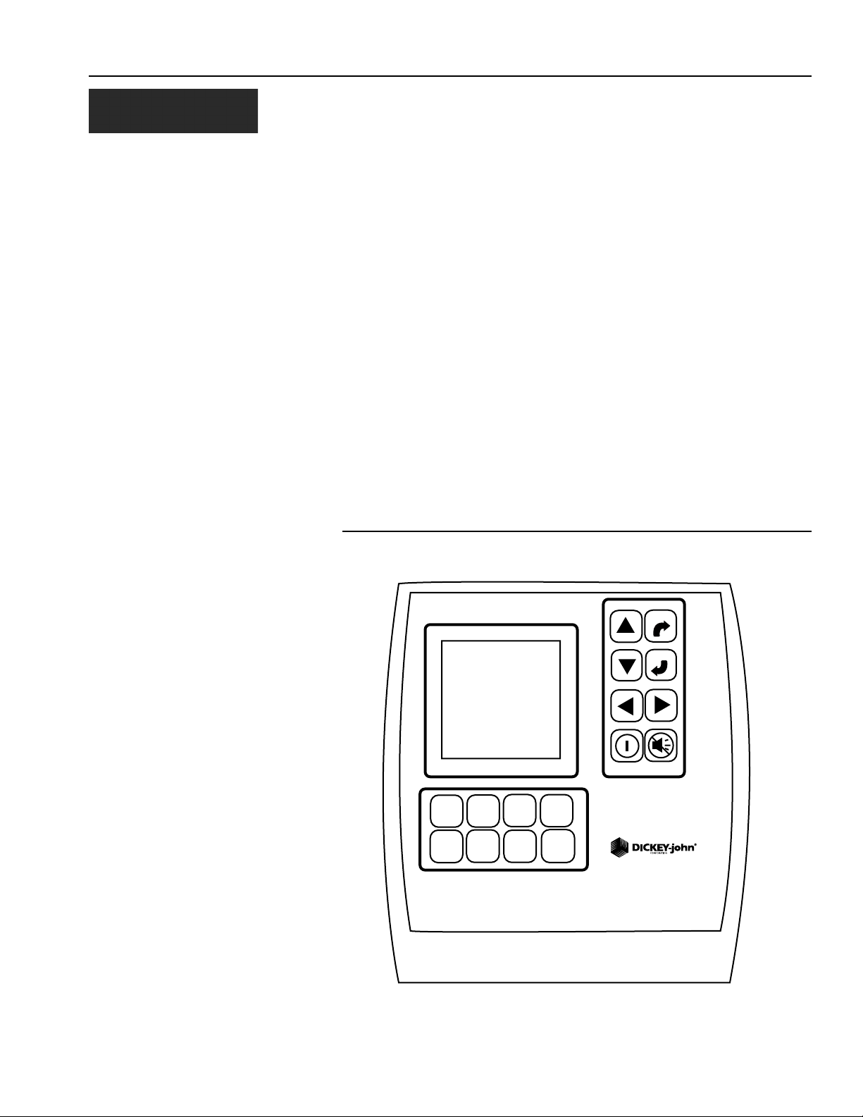
SYSTEM OVERVIEW
The DICKEY-john PM300, PM332, and PM400 Planter Monitors offer
features to monitor 16, 32, and 36 rows, respectively. The units monitor
seed or fertilizer rows, two hopper levels, and a frequency input (shaft, fan,
or flow). The monitors are compatible with DICKEY-john seed, flow, hopper
level, and gear sensors. The units store all configuration data in nonvolatile
memory, retaining information even when disconnected from power. Figure
1 provides an illustration of a generic console.
The PM300, PM332, and PM400 are designed to meet the custom needs of
individual users. The display may be configured to output a comprehensive
set of planter parameters. The user selects the type and number of
parameters to be monitored. Choices may be as simple as monitoring
population and field area or may be more complex. Similarly, blink or fail
mode information may be viewed as a bar graph, gauge, or symbol.
Information may be viewed in large format (for ease of viewing), or small
format (for entire planter view). Auto-scrolling and arrow key override are
used to maintain control of real-time information required by the user.
Figure 1
PM300, PM332, and PM400
GROUND
PLANTER
SPEED
SETUP
SETUP
ACCY
OPERATE
SETUP
LIMITS
SETUP
SEED
COUNT
MODE
DISPLAY
&
SERVICE
SPEED
AREA
MODE
ESCAPE
ENTER
PMXXX
PM300, PM332, PM400 Planter Monitors
11001-1372-200606
INTRODUCTION / 3
Page 10
OPERATOR’S MANUAL
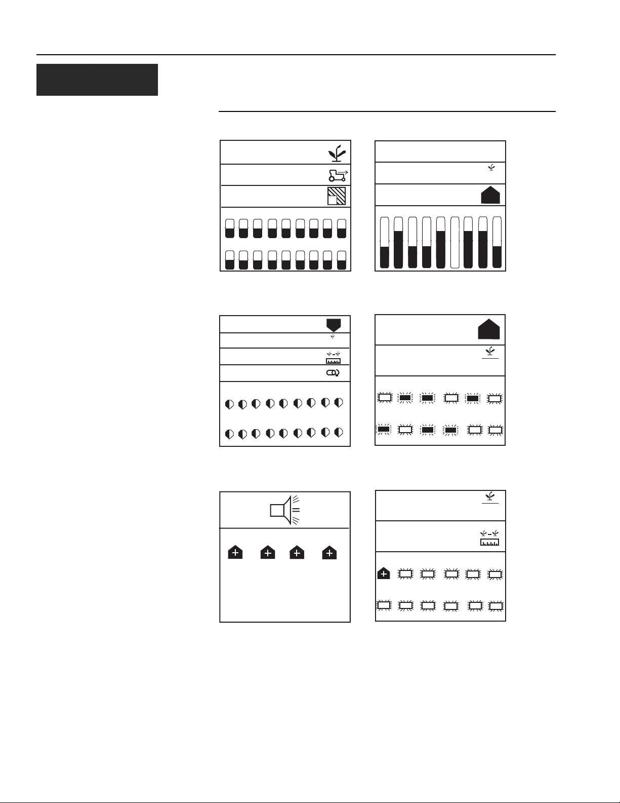
Figure 2
User-Definable Display Examples
527.3
5.2
4.5
1 2 3 4 5 6 7 8 9
10 11 12 13 14 15 16 17 18
Graphic mode: average population,
speed, and field 1 area output with bar
graphs
33.4
33.4
12.5
0.0
1 2 3 4 5 6 7 8 9
10 11 12 13 14 15 16 17 18
1
9
10
2.9
3.2
5.0
1 2 3 4 5 6 7 8 9
Text mode: average spacing, spacing
scan and min/max/avg spacing output
with bar graphs
37.2
33.5
1 2 3 4 5 6
7 8 9 10 11 12
in
6
6
10
10
Min/max/avg population, population
row scan, avg speed spacing, and shaft
speed with gauges
2 4 6 8
Rows 2, 4, 6, 8 (above limit) alarm
screen
Min/max/avg population and row scan
with blinking row symbols
33.3
2
12.5
1 2 3 4 5 6
7 8 9 10 11 12
Row scan and average spacing with
blinking symbols and row 1 hi alarm
(alarm cancel returns user to operate
screen)
4 / INTRODUCTION
PM300, PM332, PM400 Planter Monitors
11001-1372-200606
Page 11

OPERATOR’S MANUAL
SPECIFICATIONS
Power 10–16 VDC, 5 A maximum
Operating temperature range -20°C to 70°C (-4°F to 158°F)
Storage temperature range -40°C to 85°C (-40°F to 185°F)
Size 18.4 cm W x 20.1 cm H x 4.3 cm D
(7.3" W x 7.9" H x 1.7" D)
Weight 4.4 lbs for 16-row PM300 system
4.8 lbs for 32-row PM332 system
6.4 lbs for 36-row PM400 system
*Weight includes console and attached
cables (battery power cable and signal
cable that extends to the drawbar).
Wire Harnesses The PM300, PM332, and PM400 include
integrated harnesses to supply the unit's
power (fused), ground speed input, and
sensor inputs (to drawbar). The connectors
are compatible with existing DICKEY-john
harnesses. DICKEY-john can supply
custom harnesses required for sensor
inputs.
Sensors Compatible with existing DICKEY-john
sensors
Standard mounting Rear attached horizontal or vertical
mounting bracket
Mounting bracket weighs 1.0 lb.
Optional mounting Three-axis adjustable mounting bracket
Contrast adjustment Automatic temperature compensation for
contrast
Backlight adjustment Three settings for full sun, daytime, or
nighttime use
CE certified
Dust and moisture resistant
PM300, PM332, PM400 Planter Monitors
11001-1372-200606
INTRODUCTION / 5
Page 12

OPERATOR’S MANUAL
6 / INTRODUCTION
PM300, PM332, PM400 Planter Monitors
11001-1372-200606
Page 13

OPERATOR’S MANUAL
MAJOR FEATURES
PERFORMANCE
• Planter monitoring of 16 row (PM300), 32 rows (PM332), or 36 rows
PM400
• Monitoring of ground speed, two hopper levels, one frequency function
(fan, shaft, or flow)
• Easy and flexible configuration
• User-definable view of two, three, or four functions (all are available):
– Average Population
– Average Seed Spacing
– Average Seeds Per Distance
– Population Row Scan
– Seed Spacing Row Scan
– Seed Per Distance Row Scan
– Minimum, Maximum, Average Row Population
– Minimum, Maximum, Average Row Spacing
– Minimum, Maximum, Average Spacing Per Distance
– Field Area 1
– Field Area 2
– Total Area 3
– Ground Speed
– Fan, Shaft, or Flow Frequency
• User-definable row information:
–Bar Graph
– Wiper Gauge
– Symbols (Failure mode)
– Symbols flashing proportional to seeding rates
PM300, PM332, PM400 Planter Monitors
11001-1372-200606
CONSOLE/DISPLAY
• Large, user friendly keys
• User-definable text size ease of viewing
• Graphic or text-based output labels
• Backlit graphic display for nighttime use
• Three-level backlight intensity adjustment
• Large, concise error messages displayed with audible alarm
• English or metric units
• Horizontal and vertical mounting (optional 3D adjustment bracket)
COMPATIBILITY
• Compatible with DICKEY-john sensors
• Plug-in replacement for other DICKEY-john monitors
• Optional support of RS-232 based data logging
USER AID
•Help card
MAJOR FEATURES / 7
Page 14

OPERATOR’S MANUAL
8 / MAJOR FEATURES
PM300, PM332, PM400 Planter Monitors
11001-1372-200606
Page 15
OPERATOR’S MANUAL
PLANTER
SETUP
QUICK START GUIDE
Three inputs are required for monitor operation.
• Number of rows
• Row spacing
• Ground speed constant
Selecting a pre-programmed planter configuration provides easy set-up of
planter row width, number of rows, implement width, and row types.
PLANTER CONFIGURATION
Planter Setup key
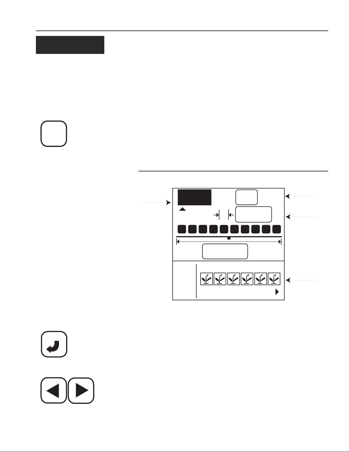
To program the planter configuration, select the Planter Setup key. The
Planter Configuration screen will be displayed.
Figure 3
Planter Configuration Screen
Planter
Configuration
123
20.00
1 2 3 5 6
I/O
PLANTER CONFIG #
16
#
in
15.0
ft
4
# of Rows
Row Spacing
Row Setup
ENTER
Enter key
Left and Right Arrow keys
PM300, PM332, PM400 Planter Monitors
11001-1372-200606
The PM300, PM332, and PM400 can store three planter configurations for
users with split row planters or multiple planters and seeders, but many
users store only one configuration.
To select a planter configuration number (1, 2, or 3)
1. Press Enter to highlight arrow indicator ( S ) and move using the Left
and Right keys to make a selection.
2. Press Enter to confirm the selection.
NUMBER OF ROWS
To change number of rows:
1. Use the Left and Right Arrow keys to highlight the number of rows
field.
QUICK START GUIDE / 9
Page 16
OPERATOR’S MANUAL
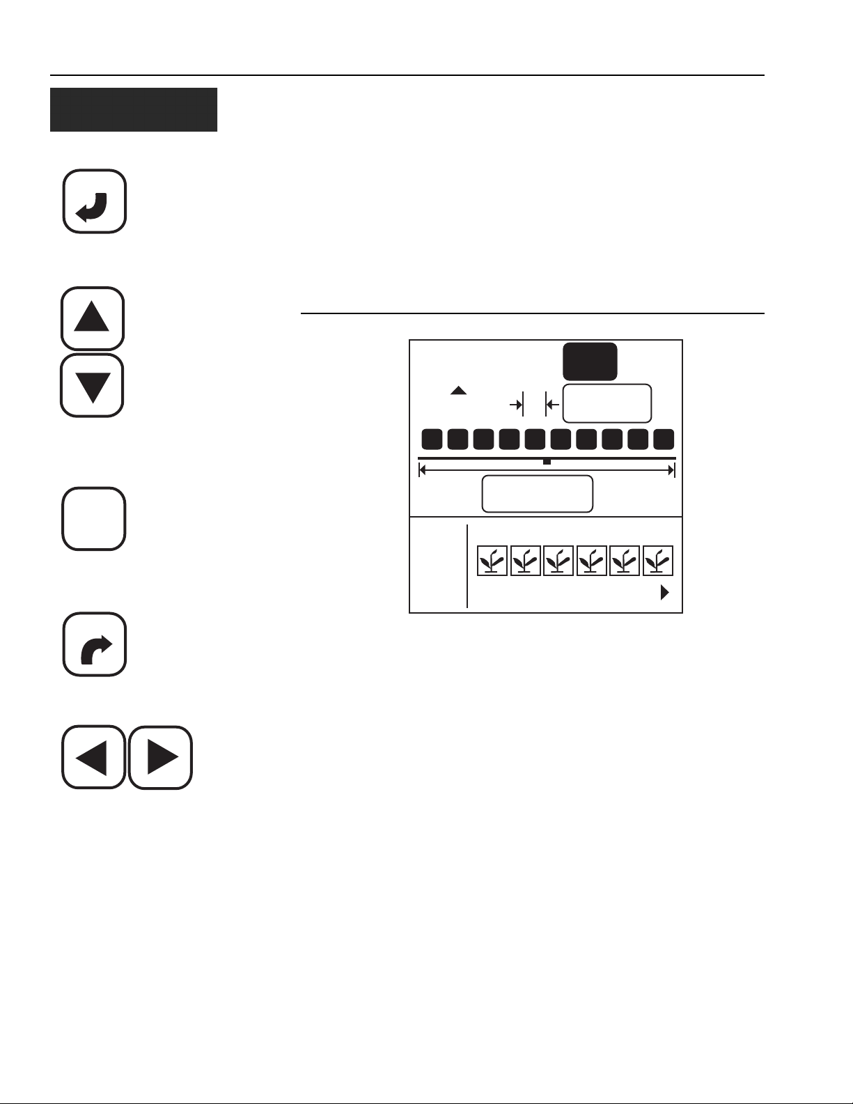
ENTER
Enter
2. Press Enter to modify the number of rows as shown in Figure 4. Use
the Right and Left Arrow keys to select the digit to change. Use the
Up and Down Arrow keys to edit the selected digit. Use the Up Arrow
key to increase the value; use the Down Arrow key to decrease the
value.
3. Press the Enter key to confirm the selection. Enter the row spacing in
the same manner.
4. Once the new values are entered, select either the Escape or Operate
key to return to the Operate (main) screen.
Figure 4
Number of Rows Screen
Up and Down Arrow keys
OPERATE
Operate key
ESCAPE
Escape key
Left and Right Arrow keys
123
15.00
1 2 3 5 6
I/O
NUMBER OF ROWS
ROW SPACING
To change row spacing:
1. Press Planter Setup key.
2. Use the Down arrow to highlight the row spacing field (refer to Figure
5).
3. Press Enter to select the field.
4. Use the Left and Right Arrow keys to select a digit for editing.
5. When a digit is highlighted, use the Up and Down Arrow keys to edit
the value displayed. Use the Up Arrow key to increase the value; use
the Down Arrow key to decrease the value.
6. When the field shows the correct planter row spacing, press Enter to
confirm the selection.
7. Once the new values are entered, select either the Escape or Operate
key to return to the Operate (main) screen.
12
#
in
15.0
ft
4
10 / QUICK START GUIDE
PM300, PM332, PM400 Planter Monitors
11001-1372-200606
Page 17
OPERATOR’S MANUAL
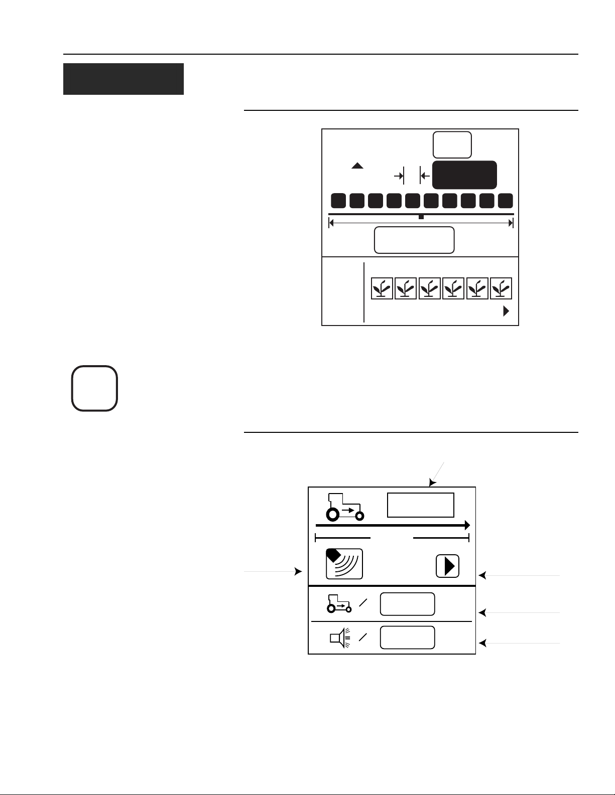
Figure 5
Row Spacing Screen
GROUND
SPEED
SETUP
Ground Speed Setup key
123
in
10.00
1 2 3 5 6
I/O
ROW SPACING
#
8
15.0
ft
4
GROUND SPEED CONFIGURATION
To perform Ground Speed Configuration, select the Ground Speed Setup
key. The Ground Speed Setup screen will display (refer to Figure 6).
Figure 6
Ground Speed Setup Screen
Ground Speed
Source
(Radar or
Reluctance)
400 ft
=
=
# of pulses in 400 ft.
6096
0.0
0.0
mph
mph
Start symbol (will
change to
Stop symbol when
test begins
Manual ground
speed (optional)
Maximum speed
alarm (optional)
PM300, PM332, PM400 Planter Monitors
11001-1372-200606
QUICK START GUIDE / 11
Page 18

OPERATOR’S MANUAL
ENTER
Enter key
OPERATE
Operate key
ESCAPE
To perform a new calibration:
1. Measure a 400 foot (122 meter) course, clearly marking the beginning
and end.
2. Using the Arrow keys, highlight the Start softkey on the screen ( X ).
3. Begin moving the tractor forward at 2-5 mph.
4. When the tractor is even with the beginning marker, press the Enter
key to start the 400-foot calibration.
5. After the calibration has begun, the softkey on the screen will change
to a Stop ( ) softkey. Drive 400 feet and stop the vehicle.
6. Select the Enter key to stop the calibration. The new calibration factor
will be displayed on the window.
7. Once the Stop key is selected, the value will be saved upon screen
exit. Selecting the Escape key while the calibration is running will not
save the value.
8. Select either the Escape or Operate key to return to the Operate
(main) screen.
Escape key
HELP CARD
The help card (Figure 7) may be cut out to provide a compact reference for
definitions, set-up screens, and general operating information.
12 / QUICK START GUIDE
PM300, PM332, PM400 Planter Monitors
11001-1372-200606
Page 19

OPERATOR’S MANUAL
Figure 7
Help Card
123.4
10
#
123
in
12.50
1 23
I/O
789
Planter Setup
15.0
ft
456
10 11 12
400 ft
=
=
Ground Speed
33.3
16.8
16.9
123456789
Operate (main) Accessory Setup
1
6096
0.0
0.0
3,0
3,0
3,0
mph
mph
%
+
Limits Setup
1
9,521
2
9,521
3
9,521
4
9,521
5
9,521
6
9,521
7
8
9
9,521
9,521
9,521
Seed Count
3
%
0.0
0.0
0.0
0.0
%
0
+
10
9,521
11
9,521
12
9,521
13
9,521
14
9,521
15
9,521
16
9,521
17
9,521
18
9,521
43.8
1234
%
123
M
E
E
User Preference
Speed Area Distance
5.1
0.0
17.217.2
14.1
31.4
0.0
Use keys to select screen
Use (arrow keys) to select item
Use ENTER to modify highlighted item
Use (arrow keys) to change items/digits or to select digits
Use ENTER to accept data or OPERATE to accept data and return to the
OPERATE screen
Population
Average
Seed Spacing Seeds per Distance
...
Functions (top half )
1
2
12
123456789
Field Area 1
Display and Service Menus
123.4
43.8
1234
M: 0305022109
1
B: 0205030714
2
1
aA
123
Rows output
(bottom half )
1
3
10,910.0
1
Field Area 2 Total Area
2
H: 1
25.7
12.8
2
Service
0000
0000
ac
III.I
III.I
123
2
...
1,2,3
Population
Seed Spacing Seeds per Distance
Row
Scan
Minimum
Population
Seed Spacing Seeds per Distance
Maximum
Average
Warning Hi/Lo No flow
!
Start
Alarm
Stop
English/Metric
M
E
...
...
Reset
Back light
Speed
Area/hour Distance
Shaft
Hopper
All Rows Failed
Planter Lifted
Security Password Save Password
Graphic/Text Label
Population Adjust+Response Rate
aA
Fan Flow
No Speed Input
Configuration
PM300, PM332, PM400 Planter Monitors
11001-1372-200606
QUICK START GUIDE / 13
Page 20

OPERATOR’S MANUAL
14 / QUICK START GUIDE
PM300, PM332, PM400 Planter Monitors
11001-1372-200606
Page 21

OPERATOR’S MANUAL
KEY FUNCTIONS
Figure 8
Keys
ESCAPE
ENTER
On/Off key
Alarm Cancel key
PLANTER
SETUP
OPERATE
GROUND
SPEED
SETUP
ACCY
SETUP
LIMITS
SETUP
SEED
COUNT
MODE
DISPLAY
&
SERVICE
SPEED
AREA
MODE
PMXXX
ON/OFF KEY
The On/Off key activates the unit. During power up, the monitor performs
internal self-tests, illuminates the display, sounds the alarm, and determines
which sensors are connected to the system. Pressing and holding the key
for one second when the power is ON will turn the power OFF, independent
of the screen being displayed.
ALARM CANCEL KEY
During normal operation, selecting the Alarm Cancel key acknowledges
the alarm condition displayed on the screen. Active row alarms are reset
after an ALL ROWS FAILURE condition or a power down-up sequence
occurs. If the error condition continues, the key must be selected again to
cancel the alarm. When no alarms are active, the volume may be modified
by selecting and holding the Alarm Cancel key.
PM300, PM332, PM400 Planter Monitors
11001-1372-200606
KEY FUNCTIONS / 15
Page 22

OPERATOR’S MANUAL
ENTER
Enter key
ESCAPE
Escape key
Up and Down Arrow keys
ENTER KEY
TTe Enter key selects a highlighted item for data modification. After
changing the parameter values, Enter accepts the modified data.
ESCAPE KEY
On the Operate (main) screen, select and hold the Escape key for four
seconds to clear an area accumulator if it is located on the top line of the
display.
When navigating through sub-menus, the Escape key moves the user back
one selection. After changing parameter values, selecting Escape accepts
the modified data. The Escape key also serves as an alarm cancel key.
UP AND DOWN ARROW KEYS
On the Operate (main) screen, the Up and Down Arrow keys are used to
manually select the parameters viewed at the top of the display. They are
inactive if all parameters are already displayed (number of parameters are
equal to or less than number of lines).
On the Operate (main) screen, the arrows are used to navigate between
options. On set-up screens, the arrows are used to navigate between
options or to change a digit/option.
Left and Right Arrow keys
OPERATE
Operate key
PLANTER
SETUP
Planter Setup key
LEFT AND RIGHT ARROW KEYS
On the Operate (main) screen, the Left and Right Arrow keys are used to
manually select the rows viewed at the bottom of the display. They are
inactive if all rows are already displayed. On other screens, the arrows are
used to navigate between options.
OPERATE KEY
The Operate (home) key is used to return the user to the Operate (main)
screen.
If data is changed, it is saved when this key is selected.
PLANTER SETUP KEY
The Planter Setup key is used to navigate to the Planter Setup screen for
input of the number of rows, row spacing, implement width (optional), and
row type (population — default, blockage, skipped, or disabled).
If data on another screen is changed, it is saved when this key is selected.
16 / KEY FUNCTIONS
PM300, PM332, PM400 Planter Monitors
11001-1372-200606
Page 23

OPERATOR’S MANUAL
GROUND
SPEED
SETUP
Ground Speed Setup key
GROUND SPEED SETUP KEY
The Ground Speed Setup key is used to navigate to the Ground Speed
Setup screen for input of the ground speed calibration (or manual entry of
ground speed calibration number), manual ground speed (used if no ground
speed is available), and ground speed maximum limit (optional).
If data on another screen is changed, it is saved when this key is selected.
LIMITS SETUP KEY
LIMITS
SETUP
Limits Setup key
DISPLAY
&
SERVICE
Display and Service key
ACCY
SETUP
Accessory Setup key
The Limits Setup key is used to navigate to the Limits Setup screen for
input of the upper limit (optional), target population value (optional), lower
limit (optional), population adjustment factor (optional for sensors that count
less than 100% of all seeds), and response rate (optional to increase or
decrease the console’s response rate).
If data on another screen is changed, it is saved when this key is selected.
DISPLAY AND SERVICE KEY
The Display And Service key is used to navigate to the Display & Service
Setup screen for access to the function, row indicators, service, and
security sub-menus; English/Metric units selection; display backlight
intensity; and alarm volume.
If data on another screen is changed, it is saved when this key is selected.
ACCESSORY SETUP KEY
The Accessory Setup key is used to navigate to the Accessory Setup
screen for selection of a fan (RPM) / shaft (RPM) / or flow (G/MIN or L/min)
labels, upper and lower alarm limits, and calibration (or manual calibration
number entry).
If data on another screen is changed, it is saved when this key is selected.
SEED
COUNT
MODE
Seed Count Mode key
SPEED
AREA
MODE
Speed Area Mode key
PM300, PM332, PM400 Planter Monitors
11001-1372-200606
SEED COUNT MODE KEY
The Seed Count Mode key is used to navigate to the Seed Count screen.
This mode allows users to test planters for proper operation prior to field
use.
If data on another screen is changed, it is saved when this key is selected.
SPEED AREA MODE KEY
The Speed Area Mode key is used to navigate to the Speed Area
Distance screen. This mode allows use of the console for non-planting
operations. This mode is also used to start, stop, or clear the three
independent area accumulators (FIELD AREA 1, FIELD AREA 2, and
TOTAL AREA).
If data on another screen is changed, it is saved when this key is selected.
KEY FUNCTIONS / 17
Page 24

OPERATOR’S MANUAL
6096
00.0
mph
400ft
=
0.0
mph
=
GNDSPD CONSTANT
A highlighted digit can be edited by
using the Arrow keys on the Control
Panel. Press Enter to accept
and confirm the selection.
ENTER
ESCAPE
EDITING SCREEN FIELDS USING KEYS
The term “highlight” used throughout the manual refers to pressing a key to
activate and move the blinking cursor until the desired digit on the screen is
highlighted. Pressing Enter accepts and confirms the selection.
HIGHLIGHTED DIGIT FOR EDITING
18 / KEY FUNCTIONS
PM300, PM332, PM400 Planter Monitors
11001-1372-200606
Page 25

OPERATOR’S MANUAL
INSTALLATION
The monitor is tested and inspected before shipping to ensure the unit is
fully operational and meets measurement specifications. Inspect for
damage that may have occurred during transit. Save all packing materials
until the inspection is complete. If damage is found, immediately file a claim
with the carrier and notify your DICKEY-john Sales Representative.
STANDARD MOUNTING BRACKET
NOTE: When mounted to a vertical
surface, a tie-wrap may be
used to secure the cables to the
bottom of the bracket.
Install the mounting bracket at the desired location using locally acquired
hardware. Install the console to the bracket by aligning the console mating
grooves with the bracket and sliding the console onto the bracket until the
snap engages.
Figure 9
Standard Mounting Bracket
Slide console
until snap
engages
Mount on vehicle
with locally acquired
hardware
PM300, PM332, PM400 Planter Monitors
11001-1372-200606
The console must not obstruct the view of the operator or interfere
with the operation of the tractor.
To prevent damage to the console, be sure the snap fully engages
during installation.
INSTALLATION / 19
Page 26

OPERATOR’S MANUAL
OPTIONAL MOUNTING 3D ADJUSTABLE BRACKET
Separate the bracket halves from one another by loosening the wing bolt.
Install the upper bracket half into the console by sliding the bracket’s
rectangular section into the console mating grooves until the snap engages.
Install the bottom bracket half at the location of your choice using locally
acquired hardware.
Figure 10
Optional 3D Mounting Bracket
Slide console
until snap
engages
Wing bolts
Mount on vehicle
with locally acquired
hardware
The console must not obstruct the view of the operator or interfere
with the operation of the tractor.
To prevent damage to the console, be sure the snap fully engages
during installation.
20 / INSTALLATION
PM300, PM332, PM400 Planter Monitors
11001-1372-200606
Page 27

OPERATOR’S MANUAL
INSTALLING CONSOLE HARNESSES
Several harnesses are located at the bottom of the PM300, PM332, and
PM400. These include power, ground speed sensor, and sensor inputs
(rows, lift switch, two hopper levels, and one frequency function [shaft/fan/
flow]).
Figure 11
Console Harnesses
ESCAPE
ENTER
Battery
GROUND
DISPLAY
LIMITS
PLANTER
SPEED
&
SETUP
SETUP
SETUP
SERVICE
PMXXX
SPEED
SEED
ACCY
AREA
COUNT
OPERATE
SETUP
MODE
MODE
+
Ground
Implement
*
Speed
(rows and accessories)
*PM300 does not have a second cable
PM332 has a 9 pin accessory cable
PM400 has a 37-pin cable
1. Route the power harness to a +12 V source near the battery if
possible.
2. Route the ground speed sensor harness connection to the RADAR,
Hall Effect, or GPS ground speed sensor.
3. Route the implement harness to the location of choice, typically near
the drawbar.
PM300, PM332, PM400 Planter Monitors
11001-1372-200606
The harnesses must not obstruct movement of the operator or of
the moving parts of the tractor or implement. Take care when
routing harnesses to secure them at proper locations; provide
slack as needed to allow for movement.
Poor +12 V connections may cause intermittent console operation.
Be sure to connect the power harness to a clean, well-conditioned
source (direct battery connection is preferred).
INSTALLATION / 21
Page 28

OPERATOR’S MANUAL
INSTALLING IMPLEMENT HARNESS AND SENSORS
The implement harness provides custom fit and functions required by the
implement. Each harness branch is labeled for location (row 1, row 2, etc.)
or sensor (lift switch) for routed connection. Some sensors may require
special adapters for connection.
Figure 12
Implement Harness/Sensors
Implement connector(s)
rows and accessories
Row1Row2Row3Row4Row5Row
6
Row
Row
7
8
Seed sensors
1. Install sensors onto seed tubes using tie-wraps.
2. Route implement harness to the appropriate locations; provide slack
near moving parts to allow for movement. Attach harness to the
implement using tie-wraps.
3. Make sure the hitch connections will connect to the tractor connections
with the proper amount of slack for implement movement.
The harnesses must not obstruct moving parts of the tractor or
implement. Take care when routing harnesses to retain them at
proper locations with adequate slack for movement.
22 / INSTALLATION
PM300, PM332, PM400 Planter Monitors
11001-1372-200606
Page 29

OPERATOR’S MANUAL
PLANTER
SETUP
Planter Setup key
ADVANCED SETUP
The monitor is designed for ease of basic monitoring by new users while
supporting expanded features for advanced users. The user may decide
which features to configure.
PLANTER AND GROUND SPEED (REQUIRES DATA ENTRY)
The two setup screens that require input for the system to function as a
monitor are the Planter Setup screen (Figure 13) and the Ground Speed
Setup screen (Figure 14).
Figure 13
Planter Setup Screen
Planter
Configuration
123
20.00
1 2 3 5 6
I/O
PLANTER CONFIG #
ROW SETUP (AUTO ASSIGNED)
The console will automatically assign the number of rows defined on the
Planter Setup screen as ON (population rows).
Rows may be configured to ON (population), OFF (split row), FLOW
(blockage), or DISABLED.
• When ON is selected (plant), the row is active and the console
will detect sensors and seed flow.
16
#
in
15.0
ft
4
# of Rows
Row Spacing
Row Setup
PM300, PM332, PM400 Planter Monitors
11001-1372-200606
• When OFF is selected (blank), the row is removed and remaining
rows are re-numbered. This is used for split row systems where every
other row or sets of internal rows are not planting. Their corresponding
row number is ignored, allowing for true planting operations to be
displayed on the monitor.
ADVANCED SETUP / 23
Page 30

OPERATOR’S MANUAL
ENTER
Enter key
Left and Right Arrow keys
• When DISABLED is selected (circle with slash), the row input is
ignored. The row number will be displayed. This is used when a row or
sensor is malfunctioning and the operator wants to disable monitoring
on that row.
• When FLOW is selected (funnel), the row will not be included for
population calculations but will be monitored for flow. The flow rows will
be used to detect flow (fertilizer or seeds) and alarm if the flow falls
below two pulses per second.
The Planter Setup screen must include the number of rows and the row
spacing or implement width for the console to properly display population.
Up to three individual configurations can be programmed and supports split
row planters (CONFIGURATION 1 for NORMAL and 2 for SPLIT ROW) and
a separate seeder or drill (CONFIGURATION 3).
To configure row setup:
1. Highlight the 123 (refer to Figure 13) at the upper left corner of the
screen
2. Press the Enter key
3. Use the Left and Right Arrow keys to select the appropriate planter
configuration.
4. Press Enter to accept selection.
5. Press the Down Arrow key to highlight the I/O icon for row setup.
6. Press the Enter key to select the icon and highlight the first row unit.
7. Use the Up or Down Arrow key to toggle through the four possible
configurations: On, Off, Disabled or Flow.
8. Use the Left or Right Arrow key to highlight another row unit for
reconfiguring.
9. Press the Enter key to save the selection.
10. Press Enter key again to select another row to change and the Left or
Right Arrow key to move to other row units to reconfigure.
11. When finished, press Operate key to return to the Operate (main)
screen.
Up or Down Arrow keys
GROUND
SPEED
SETUP
Ground Speed Setup key
24 / ADVANCED SETUP
GROUND SPEED SETUP
The Ground Speed Setup screen must include a calibration factor for
proper calculation and display of ground speed. Also included on the
Ground Speed Setup screen are a calibration aid, a manual ground speed
value, and a maximum speed alarm. The calibration aid may be used to
measure the calibration factor, which is the number of pulses in 400 ft (122
m). The manual ground speed (optional) may be used when a ground
speed sensor is not installed or has failed in the field. The maximum speed
alarm (optional) provides the user with an over-speed alarm.
PM300, PM332, PM400 Planter Monitors
11001-1372-200606
Page 31

OPERATOR’S MANUAL
Figure 14
Ground Speed Setup Screen
# of pulses in 400 ft.
6096
NOTE: To verify that the correct
calibration number has been
obtained, move to the Speed
Area Mode screen. Verify that
the speed matches the
vehicle’s speedometer or
remeasure the 400-foot
distance.
Ground Speed
Source
(Radar or
Reluctance)
400 ft
=
=
0.0
0.0
mph
mph
Start symbol (will
change to
Stop symbol when
test begins
Manual ground
speed (optional)
Maximum speed
alarm (optional)
MANUAL GROUND SPEED CONSTANT ENTRY
A manual ground speed value should only be entered when the ground
speed sensor or tractor radar has failed and no ground speed input is
available.
IMPORTANT: Entering a manual ground speed value when the ground
speed sensor or tractor radar is working properly and
connected to the monitor will interfere with the proper
operation of the planter monitor. Accumulated acreage
will not be recorded.
To enter a manual ground speed value:
Up or Down Arrow keys
ENTER
Enter key
PM300, PM332, PM400 Planter Monitors
11001-1372-200606
1. Press the Ground Speed Setup key to access the ground speed setup
screen.
1. Use the Down Arrow key to highlight the manual ground speed value
(refer to Figure 6).
2. Select the Enter key to modify the constant.
3. Use the Arrow keys to select digits, increment, and decrement values.
4. Select the Enter key to accept the new number.
5. Once the new values have been entered, select either the Escape or
Operate key to return to the Operate (main) screen.
Any non-zero value will activate manual ground speed. Set manual ground
speed to zero to disable.
To verify that the correct calibration number has been obtained, move to the
Speed Area Mode screen.
1. Press the Speed Area Mode key.
ADVANCED SETUP / 25
Page 32

OPERATOR’S MANUAL
1
5.1
0.0
2
17.217.2
12
14.1
31.4
0.0
Field Area 1
Field Area 2
Total Area
Distance
Reset
Counter
Stop
Start
SPEED
AREA
MODE
2. Verify that the speed matches the vehicle’s speedometer or
re-measure the 400-foot distance.
Figure 15
Speed Area Mode Screen
ACCY
SETUP
ACCESSORY SETUP (OPTIONAL)
To add an auxiliary sensor and its performance characteristics (calibration
values, limits, etc.) to the monitoring inputs, it must be activated by entering
a calibration constant. If minimum or maximum alarms are desired, the
limits may be added to the calibrated sensors. A fan, shaft, or flow sensor
may be monitored with HI and/or LOW alarms or no alarm values. Refer to
Figure 16.
26 / ADVANCED SETUP
PM300, PM332, PM400 Planter Monitors
11001-1372-200606
Page 33

OPERATOR’S MANUAL
Figure 16
Accessory Screen
ACCY
SETUP
Left and Right Arrow keys
Fan
Shaft
Flow
3,0
3,0
3
3,0
To enter a calibration constant:
1. Press Accessory Setup key.
2. Use the Left and Right key to select fan, shaft or flow symbol.
3. Use the Down Arrow key to change high and low alarm values.
4. Press Enter to Highlight digit to change. If the calibration factor is
unknown, the monitor can determine the calibration factor by using the
built-in calibration mode.
ENTER
Enter key
Start symbol
Stop symbol
PM300, PM332, PM400 Planter Monitors
11001-1372-200606
Assure equipment is configured to be operated safely. Shaft/fan
calibration requires movement in associated equipment and
revolution counting. Flow calibration requires liquid dispensing,
catching, and measurement.
To perform a sensor calibration, highlight the Start symbol. Assure the
system is in a safe state. Start the monitor calibration by selecting the Enter
key. The Start symbol (triangle) will change to a Stop symbol (square).
Activate the shaft, fan, or flow. Count the revolutions (shaft/fan) or catch
liquid (flow) while the monitor measures pulses. Deactivate the shaft, fan, or
flow. Stop the monitor calibration by selecting the Enter key again. Highlight
the revolutions or liquid level window. Select the Enter key. Enter the
number of revolutions (shaft/fan) or gallons (flow).
ADVANCED SETUP / 27
Page 34

OPERATOR’S MANUAL
LIMITS
SETUP
LIMITS SETUP (POPULATION) (OPTIONAL)
The Limits Setup screen allows users to define several population features
(refer to Figure 17). Users may define a target population, a minimum or
under population alarm limit, a maximum or over population alarm limit, a
population adjustment factor, and a population response rate.
Figure 17
Limits Setup Screen
Up or Down Arrow keys
Left and Right Arrow keys
Hi Alarm
Target Population
33.0
%
30.0
27.0
%
%
+
HI POP ALARM
TARGET POPULATION
Target population is defined in 1000s of seeds per acre or hectare,
dependent on the unit of measurement selected. If no value is entered, the
monitor uses average population to calculate alarms or row population
indicators.
With the limits set up screen displayed as shown in Figure 17,
1. Use the Down Arrow key to highlight the target population field.
2. Press the Enter key to highlight field.
3. Use the Left or Right Arrow key to select a digit for editing.
4. When a digit is highlighted, use the Up or Down Arrow keys to edit
the value displayed.
5. When the field shows the desired target population, press the Enter
key to confirm the selection.
6. Select either the Escape or Operate key to return to the Operate
(main) screen.
0
%
+
Lo Alarm
Population Adjust
Population Filter
ENTER
Enter key
28 / ADVANCED SETUP
If no value is entered, the monitor uses average population to calculate
alarms or row population indicators.
PM300, PM332, PM400 Planter Monitors
11001-1372-200606
Page 35

OPERATOR’S MANUAL
OPERATE
Up or Down Arrow keys
ENTER
Enter key
HI POPULATION/LOW POPULATION
The Hi population and Low population values determine when an alarm or
row indicator displays to warn the operator about a population problem. If
the percentage (%) box is checked, the values are percentage based. For
example, 10% of 30,000 seeds/acre for the over population setting (33,000
seeds/acre) and for the under population setting (27,000 seeds/acre) (refer
to Figure 17). If the percentage (%) box is not checked, the values are
population based and expressed in 1000s of seeds per acre or hectare. The
over population and under population values are independent of each other
and do not have to be the same percentage value.
To change the percentage (%) box setting,
1. Use the Up or Down Arrow key to highlight the percentage (%) box.
2. Press the Enter key to toggle the setting from checked to unchecked.
To change the population value settings:
1. Use the Up or Down Arrow key to highlight the hi alarm or low alarm
field.
2. Press the Enter key to highlight the field for editing.
3. Use the Left or Right Arrow key to select a digit for editing.
4. When a digit is highlighted, use the Up or Down Arrow keys to edit
the value displayed.
5. Press Enter key to confirm the selection.
6. Press the Operate key to return to the Operate (main) screen.
Left and Right Arrow keys
POPULATION ADJUSTMENT
A population adjustment provides a means to display populations nearer
the actual versus the sensed seeding rates. This is useful when sensors do
not detect doubles, triples, etc.
To change the over population value setting:
1. Use the Up or Down Arrow key to highlight the field.
2. Press the Enter key to highlight the field for editing.
3. Use the Left or Right Arrow key to select a digit for editing.
4. When a digit is highlighted, use the Up or Down Arrow keys to edit
the value displayed.
5. Press Enter key to confirm the selection.
6. Press the Operate key to return to the Operate (main) screen.
POPULATION RESPONSE RATE
The population response rate is used to provide population display stability
for planters with few rows versus many or when the sensed application rate
does not match the actual application rate. Use the Population Filter to
stabilize population and alarm reporting.
To change population response rate:
1. Move the slide to the right when planting high seed rates and to the left
when planting low seed rates. (refer to Figure 17).
2. Press the Operate key to return to the Operate (main) screen.
PM300, PM332, PM400 Planter Monitors
11001-1372-200606
ADVANCED SETUP / 29
Page 36

OPERATOR’S MANUAL
DISPLAY
&
SERVICE
UNITS OF MEASUREMENT, BACKLIGHTING AND ALARM VOLUME CONTROL
The display screen can be customized by changing the units of
measurement to English or Metric, control backlight intensity and increase
or decrease alarm volume.
M
E
E
Units
Backlighting
Volume
Service icon
Figure 18
Display & Service Screen
123.4
M
E
123.4
43.8
43.8
1234
1 2 3
E
Service
Security
Units, Backlight, Alarm Volume
Upper
Setup
Lower
Setup
To change Units, Backlight, and Alarm Volume:
1. Press Display & Service key.
2. Press the Down Arrow key to highlight Units, Backlight or Alarm
Volume icon.
3. Press Enter to highlight the setting to change and the Up and Down
Arrow key to cycle through selection.
4. Press Enter to confirm the desired selection.
Up or Down Arrow keys
ENTER
Enter key
30 / ADVANCED SETUP
SERVICE SCREEN
The service screen provides information about the monitor’s software and
hardware versions, total hours of operation, total acres covered, battery
voltage, hopper level 1 and 2 sensor status, and lift switch status. (refer to
Figure 19).
To display the service screen:
1. Press the Display & Service key.
2. Highlight the Service icon and press Enter.
PM300, PM332, PM400 Planter Monitors
11001-1372-200606
Page 37

OPERATOR’S MANUAL
Figure 19
Service Screen
M: 0305022109
B: 0205030714
H: 1
25.7
910.0
ac
Hardware and
software versions
Total hours of
operation
Total acres
covered
Up or Down Arrow keys
Security icon
ENTER
Enter key
ESCAPE
Escape key
12.8
Battery voltage
1
Hopper Level 1 and 2
sensor status
SECURITY SCREEN
Security features allow password protection security levels to be activated
(refer to Figure 20). This prevents unauthorized personnel from modifying
key parameters in the field.
The password screen allows the operator to individually lock screens to
assure they are not modified.
To Lock and Unlock Screens:
1. Press the Display & Service key.
2. Using the Arrow keys, highlight the Security icon and press the Enter
key to enter a password.
3. Modify the digits and select the Enter key again to accept the
password.
4. Highlight the Configuration key and press Enter to navigate to the list
of screens.
5. Use the Up or Down Arrow key to highlight icon for editing.
6. Press Enter to select the Lock/Unlock icon.
7. Lock or unlock screens by pressing the Up or Down Arrow keys.
8. Press Enter key to accept Lock or Unlock.
9. Select the Escape key to return to the Password screen.
10. Highlight the padlock and select the Enter key to toggle the unlocked
state to locked. The selected screens will require input of the password
prior to modification.
2
Lift switch
status
PM300, PM332, PM400 Planter Monitors
11001-1372-200606
ADVANCED SETUP / 31
Page 38

OPERATOR’S MANUAL
Figure 20
Security Screen and Screens That May Be Locked
0000
Configuration softkey
0000
Configuration
III.I
III.I
+
-
l
...
1,2,3
Screens that may be locked
1 2 3
32 / ADVANCED SETUP
PM300, PM332, PM400 Planter Monitors
11001-1372-200606
Page 39

OPERATOR’S MANUAL
AUXILIARY MODES
NOTE: Alarms are disabled in these
modes.
NOTE: A lift switch may be used to
more accurately monitor acre
accumulators and is required
for acreage monitoring in
n o n - p l a n t i n g o p e r a t i o n s .
If a manual ground speed is
selected, the area and distance
will not accumulate in this
mode.
SPEED
AREA
MODE
U
The monitors provide modes for alternate monitor use and row unit testing.
SPEED AREA MODE
The SPEED AREA mode is used for cultivating (Figure 21). This mode
includes start/stop/reset for Field Area 1, Field Area 2, Total Area (hc3/ac3),
and distance.
Figure 21
Speed Area Mode
S
5.1
Accessory field
not supported
on this model
0.0
Stop
Start
Reset
Counter
17.217.2
14.1
31.4
0.0
1
2
1 2
Field Area 1
Field Area 2
Total Area
Distance
SEED
COUNT
MODE
PM300, PM332, PM400 Planter Monitors
11001-1372-200606
SEED COUNT MODE
The SEED COUNT mode is used to determine row unit performance when
operating in a stationary manner. A reset for all rows is included (refer to
Figure 22).
AUXILIARY MODES / 33
Page 40

OPERATOR’S MANUAL
1
2
3
4
5
6
7
8
9
10
11
12
13
14
15
16
17
18
9,521
9,521
9,521
9,521
9,521
9,521
9,521
9,521
9,521
9,521
9,521
9,521
9,521
9,521
9,521
9,521
9,521
9,521
Reset option
Figure 22
Seed Counting Mode
34 / AUXILIARY MODES
PM300, PM332, PM400 Planter Monitors
11001-1372-200606
Page 41

OPERATOR’S MANUAL
192103114125136147158
16
16.8
33.1
Upper
Lower
OPERATE
MONITORING PLANTING
OPERATE SCREEN SETUP
The Operate (main) screen provides many tools for monitoring planting.
This screen can be immediately accessed from any other screen or
sub-menu by pressing the Operate key.
The Operate screen is divided into the upper parameter window and the
lower parameter window. The operator can customize the layout and
content of both windows, but the size of the individual windows is fixed.
(refer to Figure 23).
Figure 23
Operate Screen
PM300, PM332, PM400 Planter Monitors
11001-1372-200606
CUSTOMIZING THE UPPER PARAMETER WINDOW
The Operate (Main) screen may be customized by changing the number of
parameter lines to display in the upper window, the icon selected as text or
graphic, and the planting parameter reported for each line.
An example of five parameters selected:
1 = Average population
2 = Speed
3 = Field area
4 = Total area
5 = Shaft RPM
MONITORING PLANTING / 35
Page 42

OPERATOR’S MANUAL
Figure 24
Upper Parameters Screen
1
DISPLAY
&
SERVICE
123.4
43.8
1234
Upper Parameter icon
ENTER
Parameter
Lines
Increases/Decreases
Parameter Lines
Graphics/Text Mode
2
3
1
aA
SET UPPER PARAMS
Changing Number of Parameters
The parameter lines display can be configured to show 2, 3, or 4
parameters at one time by changing the size of the parameters. The Up
and Down Arrow keys are used at the Operate screen to scroll down to
see all parameters being monitored.
To Change the Number of Parameter Lines:
1. Press the Display & Service key with the Upper Parameter icon
highlighted.
2. Press the Enter key.
3. Press the Down Arrow key to highlight the magnifying glass.
4. Press Enter key to select the icon. Use the Up or Down Arrow key to
toggle through the options for 2, 3 or 4 display lines.
5. Press Enter to confirm the selection.
Enter key
Up or Down Arrow key
36 / MONITORING PLANTING
Figure 25
Parameter Line Options
37.2
25
33.1
5.4
33.5
1 2 3 4 5 6 7 8 9
10 11 12 13 14 15 16 17 18
2 Parameter Functions 3 Parameter Functions 4 Parameter Functions
8
1 2 3 4 5 6 7 8 9
10 11 12 13 14 15 16 17 18
4.5
1
1 2 3 4 5 6 7 8 9
10 11 12 13 14 15 16 17 18
PM300, PM332, PM400 Planter Monitors
33.1
16.8
12.5
16.8
11001-1372-200606
9
13
...
Page 43

OPERATOR’S MANUAL
DISPLAY
&
SERVICE
ENTER
Enter key
Parameters may be selected to display in numerical order from the following
list. (refer to MONITORING FUNCTIONS p. 39 for additional information).
• Average Population
• Average Seed Spacing
• Average Seeds Per Distance
• Population Row Scan
• Seed Spacing Row Scan
• Seed Per Distance Row Scan
• Minimum, Maximum, Average Row Population
• Minimum, Maximum, Average Row Spacing
• Minimum, Maximum, Average Spacing Per Distance
• Field Area 1
• Field Area 2
• Total Area 3
• Ground Speed
• Fan, Shaft, or Flow Frequency
Changing Graphic or Text Icons
The planting parameters display can be configured for text or graphic icons
in the upper window.
To Change the Graphic/Text Settings:
1. Press the Display & Service key with the Upper parameter icon
highlighted.
2. Press the Enter key.
3. Use the Down Arrow key to highlight the Graphic/Text icon.
4. Press Enter key to select the icon. Use the Up or Down Arrow key to
toggle to desired setting.
5. Press Enter to confirm selection.
123
Lower Parameter icon
Up and Down Arrow keys
PM300, PM332, PM400 Planter Monitors
11001-1372-200606
CUSTOMIZING THE LOWER PARAMETER WINDOW
The lower setup screen parameters can be modified to change the row
indicator type and size. Row indicator types include blinking box (blink rate
proportional to seeding rate), solid box (indicating row failure), bar graph, or
wiper gauge.
To Change the Row Indicator Type and Row Indicator Size:
1. Press the Display & Service key with the Lower Parameter row
indicator icon highlighted.
2. Press Enter to display the lower setup screen.
3. Highlight the Row Indicator Type or Row Indicator Size icon to change.
4. Press the Up or Down Arrow key to cycle through desired setting.
5. Press Enter to accept selection.
MONITORING PLANTING / 37
Page 44

OPERATOR’S MANUAL
1 2 3 4 5 6 7 8
blinking box
solid box
bar graph
wiper gauge
SET LOWER TYPE
Row Indicator
Type
Row Indicator
Size
Left and Right Arrow keys
Figure 26
Lower Parameters Screen
Row indicator size determines the number of rows displayed on the bottom
half of the screen and may be displayed in a small, medium, or large size as
shown in Figure 27. Default setting is non-blinking box, medium size.
When more rows are configured ON than are viewable, the monitor
automatically scrolls through the rows at 5 second intervals (bar graph with
36-row machine). The operator may use the Right and Left Arrow keys to
manually select the desired rows. Automatic scrolling will restart 10
seconds after a manual selection.
Average Population
Figure 27
Row Indicator Size
33.1
16.8
1 2 3 4 5 6 7 8 9
10 11 12 13 14 15 16 17 18
Small Row Indicators Medium Row Indicators
33.1
16.8
1 2 3 4 5 6 7 8 9
33.1
16.8
1 2 3 4 5 6
Large Row Indicators
AVAILABLE PLANTING PARAMETERS
AVERAGE POPULATION
Average Population displays the average of the planter's rows that are
configured for population in thousands of seeds per acre (s/ac) or
thousands of seeds per hectare (s/ha). The population response rate and
population adjustment may be modified on the target set-up screen. This
function may be labeled with a symbol or text, depending on the text/
graphic setting.
38 / MONITORING PLANTING
PM300, PM332, PM400 Planter Monitors
11001-1372-200606
Page 45

OPERATOR’S MANUAL
Minimum/Average/Maximum Population
Population Row Scan
...
Average Spacing
...
Minimum/Average/Maximum Spacing
...
Spacing Row Scan
MINIMUM/AVERAGE/MAXIMUM POPULATION
Minimum/Average/Maximum Population alternates the display of the
minimum row, planter average, and maximum row every two seconds.
When a minimum or maximum row is displayed, the corresponding symbol
is shown with the row number.
POPULATION ROW SCAN
Population Row Scan displays the population of each of the planter’s
rows. The displayed row is incremented every two seconds. After the last
row is displayed, the scan will resequence beginning with the first active
row.
AVERAGE SPACING
Average Spacing displays the average seed spacing (inches or cm) of the
planter's rows that are configured for population. This function may be
labeled with a symbol or text, depending on the text/graphic setting.
MINIMUM/AVERAGE/MAXIMUM SPACING
Minimum/Average/Maximum Spacing alternates the display of the
minimum row, planter average, and maximum row every two seconds.
When a minimum or maximum row is displayed, the corresponding symbol
is shown with the row number.
SPACING ROW SCAN
Spacing Row Scan displays the spacing of each of the planter's rows. The
displayed row is incremented every two seconds. After the last row is
displayed, the scan will resequence beginning with the first active row.
SEEDS PER DISTANCE
Seeds Per Distance
Minimum/Average/Maximum Seeds Per Distance
Seeds Per Distance Row Scan
PM300, PM332, PM400 Planter Monitors
11001-1372-200606
Average Seeds Per Distance displays the average seeds per foot (s/ft) or
seeds per meter (s/m) of the planter's rows that are configured for
population. This function may be labeled with a symbol or text, depending
on the text/graphic setting.
MINIMUM/AVERAGE/MAXIMUM SEEDS PER DISTANCE
Minimum/Average/Maximum Seeds Per Distance alternates the display
of the minimum row, planter average, and maximum row every two
seconds. When a minimum or maximum row is being displayed, the
corresponding symbol is shown with the row number.
SEEDS PER DISTANCE ROW SCAN
Seeds Per Distance Row Scan displays the seeds per distance of each of
the planter's rows. The displayed row is incremented every two seconds.
After the last row is displayed, the scan will resequence beginning with the
first active row.
MONITORING PLANTING / 39
Page 46

OPERATOR’S MANUAL
1
Field Area 1
2
FIELD AREA 1
Field Area 1 (ac1/ha1) displays the area of Field 1 in acres (ac) or hectares
(ha) depending on the English/Metric setting. This function may be labeled
with a symbol or text, depending on the text/graphic setting.
FIELD AREA 2
Field Area 2 (ac2/ha2) displays the area of Field 2 in acres (ac) or hectares
(ha) depending on the English/Metric setting. This function may be labeled
with a symbol or text, depending on the text/graphic setting.
Field Area 2
Total A re a
Speed
Area Per Hour
TOTAL A REA
Tota l Area (ac3/ha3) displays the total field area in acres (ac) or hectares
(ha) depending on the English/Metric setting. This function may be labeled
with a symbol or text, depending on the text/graphic setting.
SPEED
Speed displays vehicle speed in miles per hour (MPH) or kilometers per
hour (km/h) depending on the English/Metric setting. This function may be
labeled with a symbol or text, depending on the text/graphic setting.
AREA PER HOUR
Area Per Hour displays the current rate of area per hour in acres per hour
(ac/hr) or hectares per hour (ha/hr) depending on the English/Metric setting.
FAN
Fan displays the fan's speed in revolutions per minute (RPM).
SHAFT
Shaft function displays the shaft's speed in revolutions per minute (RPM).
FLOW
Fan
Shaft
Flow
40 / MONITORING PLANTING
Flow displays the flow rate speed in gallons per acre (g/ac) or liters per
hectare (l/ha) depending on the English/Metric setting.
PM300, PM332, PM400 Planter Monitors
11001-1372-200606
Page 47

OPERATOR’S MANUAL
ALARMS
NOTE: An audible 2-chirp alarm is also
output during navigation or data
entry to indicate an illegal or
nonfunctional key selection.
Alarm Cancel key
Primary operating alarms are displayed on the entire screen and are
accompanied by an audible alarm.
All monitor alarms are set to a default of Zero (0) and will not activate unless
programmed per the Advanced Setup section.
HOPPER LEVEL
Hopper level alarms activate when the seed level drops below the sensor
mounting level (refer to figure 28). Alarm can be silenced by pressing the
Alarm Cancel key.
Figure 28
Hopper 1 And 2 Alarms
HOPPER 1 LOW HOPPER 2 LOW
1
2
PM300, PM332, PM400 Planter Monitors
11001-1372-200606
ROW FAILURE
A row failure alarm occurs when the console detects less than 2 seeds per
second through the seed tube. This may result from a poor or faulty
connection to the seed sensor harness. This is a solid on alarm indicating a
problem has been detected and is silenced by pressing the Alarm Cancel
key as shown in Figure 29.
Once the Alarm Cancel key is pressed, the alarm will not sound again
unless:
1. Planting condition returns to a normal state and falls again below 2
seeds per second.
2. Power on/off sequence occurs before problem is corrected.
3. An All Rows Failure alarm occurs then the console again detects less
than 2 seeds per second through the seed tube.
ALARMS / 41
Page 48

OPERATOR’S MANUAL
1 3 5 7
Row Failure
Figure 29
Row Failure Display
ALL ROWS FAILURE
An All Row Failure alarm is a unique alarm identifier (8 chirps) that
differentiates from all other alarms and triggers when no seed flow is
detected from any row unit when ground speed is detected (refer to Figure
30).
Typical scenarious to activate an All Row Failure alarm:
1. Tractor is stopped while planter is in the ground.
2. Tractor is operating with planter lifted.
3. Normal “end of run” turn around.
Figure 30
All Rows Failure Display
42 / ALARMS
PM300, PM332, PM400 Planter Monitors
11001-1372-200606
Page 49

OPERATOR’S MANUAL
HI/LOW POPULATION WARNING
The Hi and Low population alarm triggers when seed flow drops below the
population alarm limit set on the Limits Setup screen. The alarm display will
beep and flash on the screen briefly indicating row units are over or under
the desired population (refer to Figure 31). The Operate (Main) screen will
display the row unit over or under population symbol until recorrected, All
Rows Failure occurs, or sensor mechanical problems are fixed.
Figure 31
Population Limit Warning Display
2 4 6 8
2 4 6 8
FAN SPEED LO/HI LIMIT WARNING
Fan speed alarms are triggered with a solid-on alarm when any fan speed
exceeds or falls below the value entered for Fan Speed Lo/Hi Limits in the
Setup mode (Refer to Figure 32). Alarm can be silenced by pressing Alarm
Cancel key, but will re-activate if problem is not resolved.
Figure 32
Fan Speed Limit Warning Display (Optional)
LOW FAN SPEED
HIGH FAN SPEED
PM300, PM332, PM400 Planter Monitors
11001-1372-200606
ALARMS / 43
Page 50

OPERATOR’S MANUAL
SHAFT SPEED LOW/HI LIMIT WARNING
Alarm sounds when any shaft speed exceeds or falls below the value
entered for Shaft Speed Lo or Hi Limits in the Setup mode (Refer to Figure
33). Alarm can be silenced by pressing Alarm Cancel key, but will
re-activate if problem is not resolved.
Figure 33
Shaft Speed Limit Warning Display (Optional)
LOW SHAFT SPEED
HI SHAFT SPEED
FLOW LOW/HI LIMIT WARNING
An alarm will sound when flow inputs exceed or fall below the value entered
for the Flow Lo or Hi Limits in the Setup mode. (Refer to Figure 34). Alarm
can be silenced by pressing Alarm Cancel key, but will re-activate if
problem is not resolved.
Figure 34
Flow Low/ Hi Limit Warning Display (Optional)
LOW FLOW RATE
HIGH FLOW RATE
44 / ALARMS
PM300, PM332, PM400 Planter Monitors
11001-1372-200606
Page 51

OPERATOR’S MANUAL
FAILED GROUND SPEED SENSOR (PLANTING DETECTED WITHOUT GROUND SPEED)
The failed ground speed sensor alarm triggers when planting is detected
with no ground speed being reported. This may result from a poor or faulty
connection to the speed sensor or from a defective sensor. This is a 4-chirp
alarm which is acknowledged by pressing the Alarm Cancel key, but will
re-activate until the problem is corrected (refer to Figure 35).
Figure 35
Ground Speed Sensor Failure Display
GROUND SPD FAILED
=
00.0
BATTERY HI/LOW
The battery hi/low alarm triggers when battery voltage is out of range - over
voltage and under voltage. The correct power operating range is 10-16
VDC. Alarm indicates an electrical problem exists that must be corrected.
The alarm cannot be shut off and will continue to sound until corrective
action is taken (refer to Figure 36).
Figure 36
Battery Failure Display
HI BATTERY VOLTAGE
16.5
PM300, PM332, PM400 Planter Monitors
11001-1372-200606
ALARMS / 45
Page 52

OPERATOR’S MANUAL
SELF-TEST FAILURE
The Self Test Failure alarm activates at every power cycle comparing
configured number of rows to number of rows detected. Any sensor not
found during self-test or inaccurate configuration will sound alarm and
display on the Operate (main) screen. The alarm can be acknowledged by
pressing the Alarm Cancel key, but will re-activate until problem is
resolved.
Figure 37
Self Test Failure
SELF TEST FAILURE
2 4 5 6
7 8 9
11
12
10
HI GROUND SPEED EXCEEDED (OPTIONAL)
The Hi Ground Speed Exceeded alarm is triggered anytime the speed has
exceeded the mph input in the Ground Speed Setup screen. Alarm can be
silenced by pressing the Alarm Cancel key.
Figure 38
Maximum Speed Exceeded Warning Display (Optional)
HI GROUND SPEED
46 / ALARMS
PM300, PM332, PM400 Planter Monitors
11001-1372-200606
Page 53

OPERATOR’S MANUAL
TROUBLESHOOTING
MONITOR WILL NOT POWER ON
Probable Cause
1. Blown console fuse
2. Poor battery connection
3. Low battery voltage
4. Defective console
Corrective Action
1. Check fuse (located near battery connection). If needed, replace with
5.0 A fuse maximum. If fuse blows again, check all harnesses for
pinches or breaks that may cause power short to ground.
2. Be sure connections are clean and tight. Inspect harness for damage.
3. Console voltage must be at least 10 V. If low, recharge or replace
battery.
4. Console is damaged. Contact your dealer, DICKEY-john USA
(1-800-637-3302), or DICKEY-john Europe (011-33-141-192189).
ROW FAILURE OR HI/LOW ALARM WHEN ROW IS
PLANTING PROPERLY
Probable Cause
1. Seed sensor coated with dirt
2. Faulty sensor or harness
3. Defective console
Corrective Action
1. Clean sensor using a dry bottle brush.
2. Drop seed down the seed tube or place a dry bottle brush down the
seed tube to trigger sensor. Observe if troubleshooting sensor LED
mounted to the tube blinks. If sensor does not blink, replace the
sensor. If the sensor LED blinks, check harness for damage or
pinched wires. If the sensor does not have an LED, swap harness
connection with adjacent sensor to determine if sensor is damaged.
3. Console is damaged. Contact your dealer, DICKEY-john USA
(1-800-637-3302), or DICKEY-john Europe (011-33-141-192189).
PM300, PM332, PM400 Planter Monitors
11001-1372-200606
TROUBLESHOOTING / 47
Page 54

OPERATOR’S MANUAL
HOPPER ALARM DOES NOT SOUND WHEN
HOPPER IS EMPTY
Probable Cause
1. Hopper sensor coated with dirt
2. Faulty sensor or harness shorted to ground
3. Defective console
Corrective Action
1. Clean sensor using a dry bottle brush.
2. Swap harness connection with another sensor to determine if sensor
or harness is damaged. Use service screen if another sensor is not
available. Replace sensor or repair harness.
3. Console is damaged. Contact your dealer, DICKEY-john USA
(1-800-637-3302), or DICKEY-john Europe (011-33-141-192189).
HOPPER ALARM SOUNDS WHEN HOPPER IS
FULL
Probable Cause
1. Faulty sensor or harness open
2. Defective console
Corrective Action
1. Swap harness connection with another sensor to determine if sensor
or harness is damaged. Use service screen if another sensor is not
available. Replace sensor or repair harness.
2. Console is damaged. Contact your dealer, DICKEY-john USA
(1-800-637-3302), or DICKEY-john Europe (011-33-141-192189).
SYSTEM VOLTAGE ALARM
Probable Cause
1. Low battery voltage
2. Poor battery connection
3. Damaged harness
Corrective Action
1. Console voltage must be at least 10 V. If low, recharge or replace
battery.
2. Be sure connections are clean and tight. Inspect harness for damage.
3. Check all harnesses for pinches or breaks that may cause power or
8 V-sensor power short to ground.
48 / TROUBLESHOOTING
PM300, PM332, PM400 Planter Monitors
11001-1372-200606
Page 55

OPERATOR’S MANUAL
ACCESSORY ALARM SOUNDS WHEN SHAFT,
FAN, OR FLOW IS WORKING
Probable Cause
1. Sensor failure
2. Wrong calibration number
3. Incorrect limits
4. Defective console
Corrective Action
1. Shaft, fan, or flow sensor not operating. Replace defective sensors.
2. Sensor calibration number is incorrect. Check calibration number in
accessory setup screen.
3. Sensor limits are incorrect. Check limits in accessory setup screen.
4. Console is damaged. Contact your dealer, DICKEY-john USA
(1-800-637-3302), or DICKEY-john Europe (011-33-141-192189).
GROUND SPEED ALARM SOUNDS WITH
FORWARD MOVEMENT
Probable Cause
1. Ground speed sensor failure
2. Console failure
Corrective Action
1. No ground speed sensor is detected, or planting is detected on at least
one row with no ground speed. Replace faulty ground speed sensor.
2. Console is damaged. Contact your dealer, DICKEY-john USA
(1-800-637-3302), or DICKEY-john Europe (011-33-141-192189).
GROUND SPEED HIGH ALARM SOUNDS
Probable Cause
1. Ground speed alarm set too low
2. Incorrect ground speed constant
Corrective Action
1. Set ground speed alarm limit higher or to zero to disable.
2. Ground speed sensor has not been calibrated, RADAR sensor angle
has changed, or incorrect sensor constant is entered. Use SPEED,
AREA, DISTANCE mode to determine if speed is correct. If incorrect,
recalibrate speed constant (Speed Setup screen).
PM300, PM332, PM400 Planter Monitors
11001-1372-200606
TROUBLESHOOTING / 49
Page 56

OPERATOR’S MANUAL
SELF-TEST ALARM
Probable Cause
1. Faulty sensor or harness
2. Console failure
Corrective Action
1. Trigger sensor and observe troubleshooting LED. If sensor does not
have LED, swap harness connection with adjacent sensor to
determine if sensor or harness is damaged. Replace sensor or
harness.
2. Console is damaged. Contact your dealer, DICKEY-john USA
(1-800-637-3302), or DICKEY-john Europe (011-33-141-192189).
50 / TROUBLESHOOTING
PM300, PM332, PM400 Planter Monitors
11001-1372-200606
Page 57

OPERATOR’S MANUAL
CONNECTOR PIN-OUTS
Battery
Pin Label Description
Red Wire Battery +12V
Black Wire Battery Ground
PM300 Implement
Pin # Description
1 Row 1 (green)
2 Row 2 (brown)
3 Row 3 (blue)
4 Row 4 (orange)
5 Row 5 (yellow)
6 Row 6 (violet)
7 Row 7 (gray)
8 Row 8 (pink)
9 Row 9 (tan)
10 Row 10 (white/black)
11 Row 11 (red/black)
12 Row 12 (green/black)
13 Row 13 (orange/black)
14 Row 14 (blue/black)
15 Row 15 (black/white)
16 Row 16 (red/white)
17-23 No connection
24 8 V sensor power (red)
25 8 V sensor power (red/black/white)
26 Sensor return (black)
27 Sensor return (white/black/red)
28 No connection
29 Hopper 1 (green/white)
30 Hopper 2 (blue/white)
31 Shaft/Fan/Flow (black/red)
32 8 V power (red)
33 12 V switched power (white/red)
34 12 V return (black)
35 RS-232 Rx (blue/red)
36 RS-232 Tx (red/green)
37 Lift switch (orange/red)
Ground Speed
Pin # Description
1 Ground (black)
2 Signal (green)
3 Power (red)
4 Sense (white)
PM332 Implement
Pin # Description
1 Row 1 green)
2 Row 2 (brown)
3 Row 3 (blue)
4 Row 4 (orange)
5 Row 5 (yellow)
6 Row 6 (violet)
7 Row 7 (gray)
8 Row 8 (pink)
9 Row 9 (tan)
10 Row 10 (white/black)
11 Row 11 (red/black)
12 Row 12 (green/black)
13 Row 13 (orange/black)
14 Row 14 (blue/black)
15 Row 15 (black/white)
16 Row 16 (red/white)
17 Row 17 (green/white)
18 Row 18 (blue/white)
19 Row 19 (black/red)
20 Row 20 (white/red)
21 Row 21 (orange/red)
22 Row 22 (blue/red)
23 Row 23 (red/green)
24 +8 V Snsr Pwr Left (red)
25 +8 V Snsr Pwr Right (red/blk/white)
26 Ground Left (black)
27 Ground Right (white/black/red)
28 Row 24 (orange)
29 Row 25 (black/white/red)
30 Row 26 (green/black/white)
31 Row 27 (orange/black/white)
32 Row 28 (blue/black/white)
33 Row 29 (black/red/green)
34 Row 30 (white/red/green)
35 Row 31 (red/black/green)
36 Row 32 (green/black/orange)
37 Lift Switch (white)
PM300, PM332, PM400 Planter Monitors
11001-1372-200606
TROUBLESHOOTING / 51
Page 58

OPERATOR’S MANUAL
CONNECTOR PIN-OUTS
PM332 Implement Accessory Harness
Pin # Description
1 Lift Switch (light green)
2 Hopper # 1 (brown)
3 Hopper # 2 (light blue)
4 Frequency (orange)
5 +8 V Acc Power (yellow)
6 + 12 V Acc Power (purple)
7 Acc Return (gray)
8 RS-232 Rx (pink)
9 RS-232 Tx (neutral)
PM400 Implement 1
Pin # Description
1 Row 1 (green)
2 Row 2 (brown)
3 Row 3 (blue)
4 Row 4 (orange)
5 Row 5 (yellow)
6 Row 6 (violet)
7 Row 7 (gray)
8 Row 8 (pink)
9 Row 9 (tan)
10 Row 10 (white/black)
11 Row 11 (red/black)
12 Row 12 (green/black)
13 Row 13 (orange/black)
14 Row 14 (blue/black)
15 Row 15 (black/white)
16 Row 16 (red/white)
17 Row 17 (green/white)
18 Row 18 (blue/white)
19 Row 19 (black/red)
20 Row 20 (white/red)
21 Row 21 (orange/red)
22 Row 22 (blue/red)
23 Row 23 (red/green)
24 +8 V Snsr Pwr Left (red)
25 +8 V Snsr Pwr Right (red)
PM400 Implement 1 (continued)
Pin # Description
26 Sensor return left (black)
27 Sensor return right (black)
28 Row 24 (orange/green)
29 Hopper 1 (black/white/red)
30 Hopper 2 (green/black/white)
31 Shaft/Fan/Flow (orange/black/white)
32 8V power (red)
33 12V switched power (black/red/green)
34 Sensor return (black)
35 RS-232 RX (red/black/green)
36 RS-232 TX (green/black/orange)
37 Lift switch (white)
PM400 Implement 2
Pin # Description
1 Row 25 (green)
2 Row 26 (brown)
3 Row 27 (blue)
4 Row 28 (orange)
5 Row 29 (yellow)
6 Row 30 (violet)
7 Row 31 (gray)
8 Row 32 (pink)
9 Row 33 (tan)
10 Row 34 (white/black)
11 Row 35 (red/black)
12 Row 36 (green/black)
13-23 No connection
24 8 V sensor power (red/black/white)
25 8 V sensor power (red)
26 Sensor return (white/black/red)
27 Sensor return (black)
28 No connection
29 No connection
30 No connection
31 No connection
32 No connection
33 No connection
34 No connection
35 No connection
36 No connection
37 No connection
52 / TROUBLESHOOTING
PM300, PM332, PM400 Planter Monitors
11001-1372-200606
Page 59

Dealers have the responsibility of calling to the attention of their customers the following
Copyright 2006 DICKEY-john Corporation
Specifications subject to change without notice
warranty prior to acceptance of an order from their customer for any DICKEY-john product.
DICKEY-john® WARRANTY
DICKEY-john warrants to the original purchaser for use that, if any part of the product
proves to be defective in material or workmanship within one year from date of original
installation, and is returned to DICKEY-john within 30 days after such defect is discovered,
DICKEY-john will (at our option) either replace or repair said part. This warranty does not
apply to damage resulting from misuse, neglect, accident, or improper installation or
maintenance. Said part will not be considered defective if it substantially fulfills the
performance expectations. THE FOREGOING WARRANTY IS EXCLUSIVE AND IN
LIEU OF ALL OTHER WARRANTIES OF MERCHANTABILITY, FITNESS FOR
PURPOSE, AND OF ANY OTHER TYPE, WHETHER EXPRESS OR IMPLIED.
DICKEY-john neither assumes nor authorizes anyone to assume for it any other obligation or
liability in connection with said part and will not be liable for consequential damages.
Purchaser accepts these terms and warranty limitations unless the product is returned within
fifteen days for full refund of purchase price.
For DICKEY-john Service Department,
call 1-800-637-3302 in either the U.S.A. or Canada
Headquarters:
5200 Dickey-john Road, Auburn, IL 62615
TEL: 217-438-3371, FAX: 217-438-6012, WEB: www.dickey-john.com
Europe:
DICKEY-john Europe S.A., 165, boulevard de Valmy, 92706 - Columbes - France
TEL: 33 (0) 1 41 19 21 80, FAX: 33 (0) 1 47 86 00 07
Page 60

 Loading...