

Page 1
Great Plains Mfg., Inc. 1
Radar
Simulator
Power
AE6608
SN: XXXXX
MIN
MAX
AE6690
ACTUATOR
TEST BOX
SN: XXXXX
AgExpre ss Elect ronics
Sensor Tester
AE6602
S/N: XXXXX
WARNING
SN: XXXXX
AE6691
Pessure Sensor
Simulator
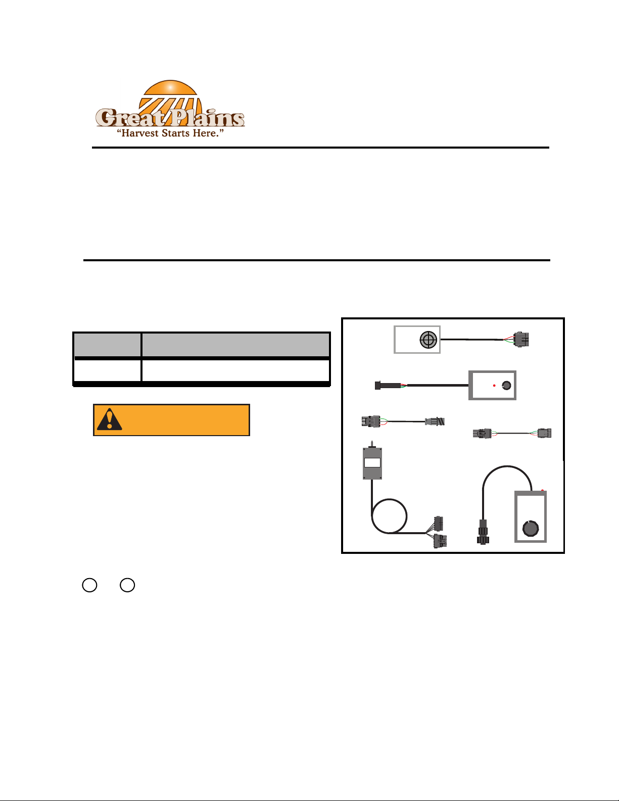
Great Plains Diagnostic Kit
All or parts of this kit can be used with:
• DICKEY-john IntelliAg
• DICKEY-john Seed Manager SE
• DICKEY-john PM300
®
®
®
General Information
These instructions explain how to use the components of the Great Plains Diagnostic Kit for
troubleshooting issues encountered with the electrical and electronic components found on
Great Plains Seeding Equipment
Kit # Description
823-401C Great Plains Diagnostic Kit
Falling Hazard:
Practice caution when working on elevated surfaces.
Make sure any ladders used have solid footing.
Notations and Conventions
“Left” and “Right” are facing in the direction of
machine travel
Call-Outs
1
to
116-008M 2/5/13
Fig. 1
9
Single-digit callouts identify components
in the currently referenced Figure. These
numbers may be reused for different items
Page 2
2 Great Plains Mfg., Inc.
2
1
AE6690
ACTUATOR
TEST BOX
SN: XXXXX
3
2
1
1
2
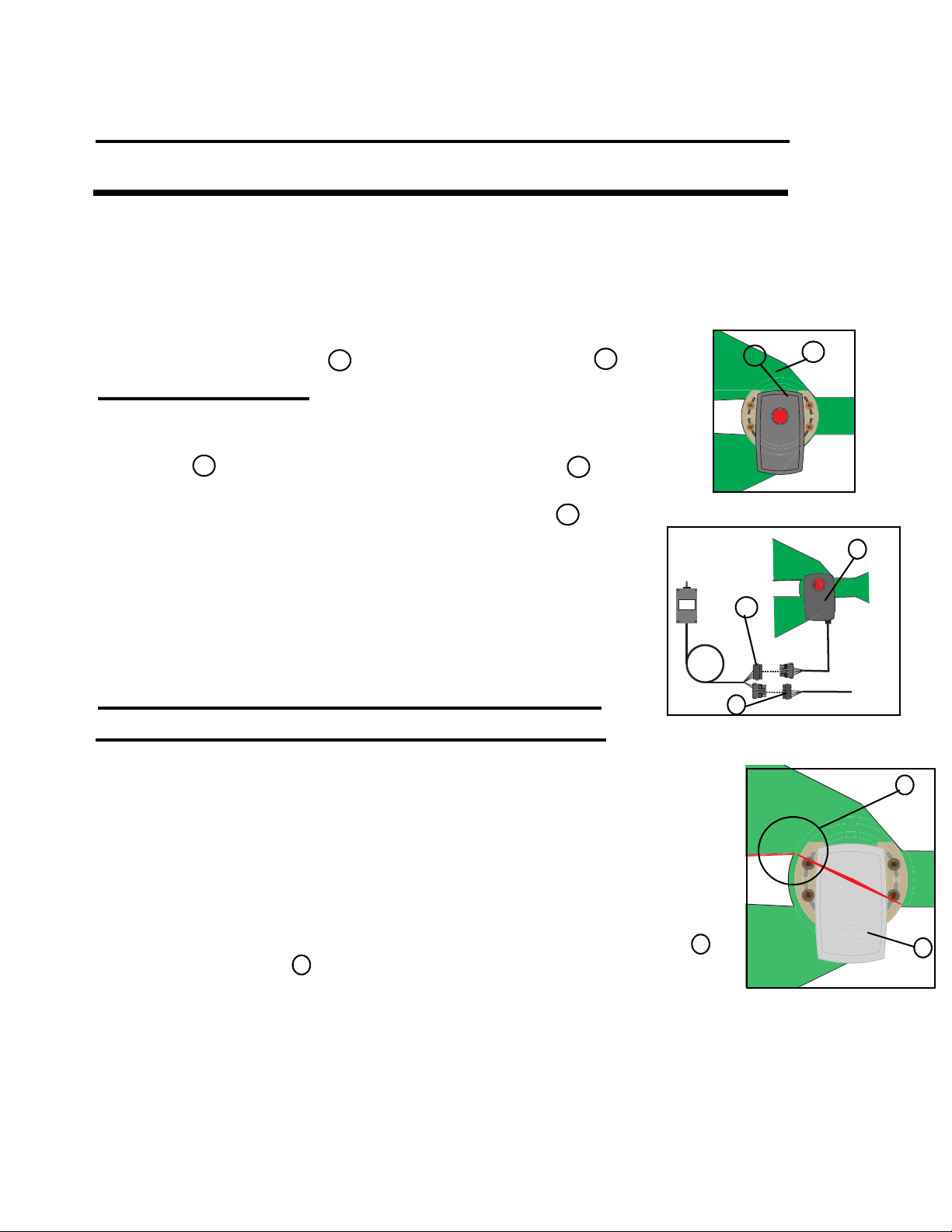
Actuator Test Box - For Air-Pro Planters.
The Actuator Test Box (part # AE6690) can be used to troubleshoot the split air actuator and as an
aid in the replacement of it if needed. The planter harness must be electrically connected to the
tractor for the switch box to function. If this is not possible, another 12VDC power supply needs
to be connected to the tower connector of the test box harness (connector with only two wires). Pin
Refer to Figure 2
1. Locate the rotary actuator on the side of the spit air valve.
1
The spit air valve is always mounted directly next to the fan.
Refer to Figure 3
2. Follow the wiring harness that comes out of the rotary
actuator until the 6 pin weatherpack connector is found.
1
Disconnect the actuator harness from the extension harness
at this location, and connect the two leads of the test box
2
2
3
Fig. 2
3. The Actuator Test Box contains a spring centered momentary
switch. Moving the switch to one side or the other will cause
the actuator to rotate either clockwise or counterclockwise.
When the switch is released, it will re-center itself and stop actuator
motion. DO NOT USE THIS TOOL AS A REPLACEMENT
FOR AIR PRESSURE CONTROL DURING PLANTING!
Using the Actuator Test Box for actuator replacement.
Fig. 3
Refer to Figure 4
1. The rotary actuator is mounted in slots to allow for adjustment to
the assembly. Leave the mounting hardware loose until final
adjustment is made.
2. Connect the test box as described above in step 2.
3. Using the test box, electrically rotate the actuator fully clockwise. (As viewed
looking at the arrow on the face of the actuator.)
4. Remove the top meter pressure delivery hose closest to the actuator and
visually inspect the location of the split air vane. Adjust the actuator until
the edge of the vane is flush with the bottom of the seed delivery outlet.
2
1
5. Tighten the mounting hardware and use the test box to operate the valve
through its entire range of travel to ensure there is no physical interference.
Notes - The rotary actuator contains internal limit switches that are set to hold its rotation within a 60 degree range.
When either switch is tripped, the actuator will stop and can only move back in the opposite direction.
- An internal circuit breaker will cut power to the actuator if it encounters a high amp load. If the actuator will
not move, check for +12VDC in pin A of the 6 pin connector using pin B for the ground. If the voltage is
present but there is no visible LED light in the window of the actuator, unplug it, wait 20 seconds and
reconnect it. This will reset the breaker.
Fig. 4
2/5/13 116-008M
Page 3
Great Plains Mfg., Inc. 3
Radar
Simulator
Power
AE6608
SN: XXXXX
MIN
MAX
Radar Simulator - for ground speed simulation on YP planters.
The Radar Simulator (part # AE6608) can be connected to the planter harness and used to
send a simulated speed pulse to the monitor system.
Refer to Figure 5
1. Locate the radar or hall effect sensor that supplies the speed signal to the monitoring
system. On YP12 and YP16 planters, the hall effect sensor is located inside the left
rear wheel. On all others, the radar sensor will be located under and in front of the
seed hopper or hoppers.
3
5
2
4
1
Fig. 5
2. Follow the wiring harness out of the sensor until the connection at the Working Set Master
harness is found.
1
3. Disconnect the sensor lead at this connection and connect the radar simulator in its place.
4. Make sure the red LED light at the top of the simulator is brightly lit. This light
4
3
2
indicates a good power supply coming from the harness. If the light is off or dimly lit,
make sure the monitor system is powered on and inspect the harness and connections.
5. Rotating the knob on the face of the simulator changes the pulse rate that it outputs.
5
A clockwise rotation will speed the pulse rate up, and a counterclockwise rotation
slows the rate down.
6. Observe the ground speed reading on the work screen or on the diagnostic screen at the
frequency digital groundspeed. If no signal is seen, check the ground speed setup in the monitor.
Also check the connection at the ground speed connection at the actuator harness.
116-008M 2/5/13
Page 4
4 Great Plains Mfg., Inc.
Radar
Simulator
Power
AE6608
SN: XXXXX
MIN
MAX
1
Radar Simulator - for fan speed simulation on YP planters
The Radar Simulator (part # AE6608) can be coupled with the Application Rate Sensor
Adapter (part # AE2607) and the Radar Sensor Adapter (part # AE2609) and connected to the
planter harness for sending a simulated fan speed pulse to the monitor system.
Refer to Figure 6
3
2
8
4
5
7
6
Fig. 6
1. Assemble the Radar Simulator together with the Radar Sensor Adapter and the
Application Rate Sensor Adapter.
1
3
2
2. Locate the wiring harness coming out of the fan speed sensor and follow it until you find
the connection at the extension harness.
4
3. Disconnect the sensor lead from the extension harness and connect the assembly made in
step one. It can also be connected to the RPM sensor lead where the extension
harness connects to the actuator harness at the working set master.
4. Make sure the red LED light at the top of the simulator is brightly lit. This light
7
5
6
indicates a good power supply coming from the harness. If the light is off or dimly lit,
make sure the monitor system is powered on and inspect the harness and connections.
5. Rotating the knob on the face of the simulator changes the pulse rate that it outputs.
8
A clockwise rotation will speed the pulse rate up, and a counterclockwise rotation
slows the rate down.
6. Observe the fan rpm reading on the work screen or on the diagnostic screen at the frequency
rpm reading. If no signal is seen, check fan rpm setup in the monitor. Also check the extension
harness and the RPM connection on the actuator harness,
2/5/13 116-008M
Page 5
Great Plains Mfg., Inc. 5
Radar
Simulator
Power
AE6608
SN: XXXXX
MIN
MAX
1
Radar Simulator - for application rate sensor simulation on YP planters
The Radar Simulator (part # AE6608) can be coupled with the Radar Sensor Adapter (part #
AE2609) and the Application Rate Sensor Adapter (part # AE2607) and connected to the
planter harness for sending a simulated application rate sensor pulse to the monitor system.
Refer to Figure 7
3
4
2
8
5
7
6
Fig. 7
1. Assemble the Radar Simulator together with the Radar Sensor Adapter and the Application
Rate Sensor Adapter.
3
1
2
2. Locate the wiring harness coming out of the application rate sensor. On YP12 and YP16
planters, this will be found at the end of the right wing drive shaft. On all others, it will be
found on the short shaft just below the seed drive motor in the center of the implement.
Follow the lead until you find the three pin connection at the extension harness.
4
3. Disconnect the sensor from the extension harness and connect the assembly made in step
one. It can also be connected to the FDBK 1 (feedback 1) lead where the extension
harness connects to the actuator harness at the working set master.
4. Make sure the red LED light at the top of the simulator is brightly lit. This light
7
5
6
indicates a good power supply coming from the harness. If the light is off or dimly lit,
make sure the monitor system is powered on and inspect the harness and connections.
5. Rotating the knob on the face of the simulator changes the pulse rate that it outputs.
8
A clockwise rotation will speed the pulse rate up, and a counterclockwise rotation
slows the rate down.
6. Observe the channel frequency pulse reading the channel 1 diagnostic screen. If no signal is
seen, check monitor setup. Also check the extension harness and the connection at FDBK 1
116-008M 2/5/13
Page 6

6 Great Plains Mfg., Inc.
AgExpress Ele ctronics
Sensor Tester
AE6602
S/N: XXXXX
MODEL 46436-117B
SERIAL
XXXXX
e24
(360 COUNT APR)
02 0019
2010 03
AgExpress Electronics
Sensor Tester
AE6602
S/N: XXXXX
Sensor Tester - for seed tube sensor testing on YP planters.
The Sensor Tester (part # AE6602) is primarily used to verify the operation of the sensor
located on the seed tube within a row unit.
Refer to Figure 8
1. Locate the row associated with the sensor
to be tested.
1
2. Locate the wiring harness coming out of the
sensor and follow it up to the top of the row
unit where it connects to the row harness lead.
3. Connect the Seed Sensor Tester to the sensor
2
lead. Any object passing through the seed
tube and past the sensor eye, will cause the
sensor to emit a pulse. With the tester connected
to the sensor, drop some seed or feed a flexible
object like a zip tie through the seed tube. If the
sensor is working correctly, the
Fig. 8
2
1
Note: The Seed Tube Sensor Tester operates on a 9 volt battery that is accessible through a door
in the back of the case. Make sure the battery is good before replacing a sensor.
Sensor Tester - for application rate sensor testing on YP planters.
The Sensor Tester (part # AE6602) can be used in conjunction with the Application Rate
Sensor Adapter (part # AE2607) to verify the operation of the application rate sensor (shaft
speed sensor).
Refer to Figure 9
1. Assemble the Seed Sensor Tester together with the
Application Rate Sensor Tester Adapter.
2. Locate the wiring harness coming out of the application
rate sensor. On YP12 and YP16 planters, this will be
3
found at the end of the right wing drive shaft. On all others,
it will be found on the short shaft just below the seed drive
motor in the center of the implement. Follow the lead until
you find the three pin connection at the extension harness.
3. Disconnect the application rate sensor lead at the extension harness and connect the assembly
made in step one to the application rate sensor.
4. The application rate sensor will create 360 pulses per revolution of its input shaft. Every
pulse created will case the sensor tester to “beep” if the sensor is functioning properly.
1
2
2
1
3
Fig. 9
Note: The Seed Tube Sensor Tester operates on a 9 volt battery that is accessible through a door
in the back of the case. Make sure the battery is good before replacing a sensor.
2/5/13 116-008M
Page 7

Great Plains Mfg., Inc. 7
AgExpress Electronics
Sensor Tester
AE6602
S/N: XXXXX
AgExpress Electronics
Sensor Tester
AE6602
S/N: XXXXX
AgExpress Electronics
Sensor Tester
AE6602
S/N: XXXXX
AgExpress Electronics
Sensor Tester
AE6602
S/N: XXXXX
AgExpress Electronics
Sensor Tester
AE6602
S/N: XXXXX
AgExpress Electronics
Sensor Tester
AE6602
S/N: XXXXX
AgExpress Electronics
Sensor Tester
AE6602
S/N: XXXXX
AgExpress Electronics
Sensor Tester
AE6602
S/N: XXXXX
Sensor Tester - for testing radar or ground speed sensors on YP planters.
The Sensor Tester (part # AE6602) can be used in conjunction with the Speed Sensor
Adapter (part # AE2609) to verify the operation of a radar or hall effect ground speed
sensor.
Refer to Figure 10
1. Assemble the Sensor Tester together with the
Speed Sensor Adapter.
2. Locate the radar or hall effect sensor that supplies
3
1
2
1
2
4
the speed signal to the monitoring system. On YP12
and YP16 planters, the hall effect sensor is located
inside the rear left wheel. On all others, the radar
sensor will be located under and in front of the seed
Fig. 10
hopper or hoppers.
3. Follow the wiring harness that comes out of the radar or hall effect sensor until you find
where it connects to the extension harness. Disconnect the sensor from the extension
harness and connect the assembly made in step one to the sensor lead.
4. If testing a hall effect sensor, wave a screwdriver or other metallic object past the end of
the sensor. Every time the object passes the end of the sensor, it should create a pulse.
This pulse will cause the sensor tester to “beep”. If testing a radar sensor, any object
waved in front of the lens should also create a pulse and cause the tester to “beep”.
Note: The Seed Tube Sensor Tester operates on a 9 volt battery that is accessible through a door
in the back of the case. Make sure the battery is good before replacing a sensor.
Sensor Tester - for testing fan speed sensors on YP planters.
3
4
The Sensor Tester (part # AE6602) can be used in conjunction with the Application Rate Sensor
Adapter (part # AE2607) to verify the operation of the hall effect fan speed sensor.
Refer to Figure 11
1. Assemble the Sensor Tester together with the
Application Rate Sensor Adapter.
2. Locate the hall effect sensor the supplies the fan speed
signal to the monitoring system. This will be the wiring
harness coming out of the screen on the fan assembly.
1
2
1
2
3
3
Fig. 11
3. Follow the harness until it connect to the extension harness. Disconnect the harness and
connect the assembly made in step one to the sensor lead.
4. If the sensor is still mounted in the fan assembly, any motion of the fan should cause the
sensor to create a pulse that will make the tester “beep”. If the sensor has been removed,
waving a metallic object like a screwdriver should produce the same result.
Note: The Seed Tube Sensor Tester operates on a 9 volt battery that is accessible through a door
in the back of the case. Make sure the battery is good before replacing a sensor.
116-008M 2/5/13
Page 8

8 Great Plains Mfg., Inc.
4
5
2
6
7
SN: XXXXX
AE6691
Pessure Sensor
Simulator
1
8
9
3
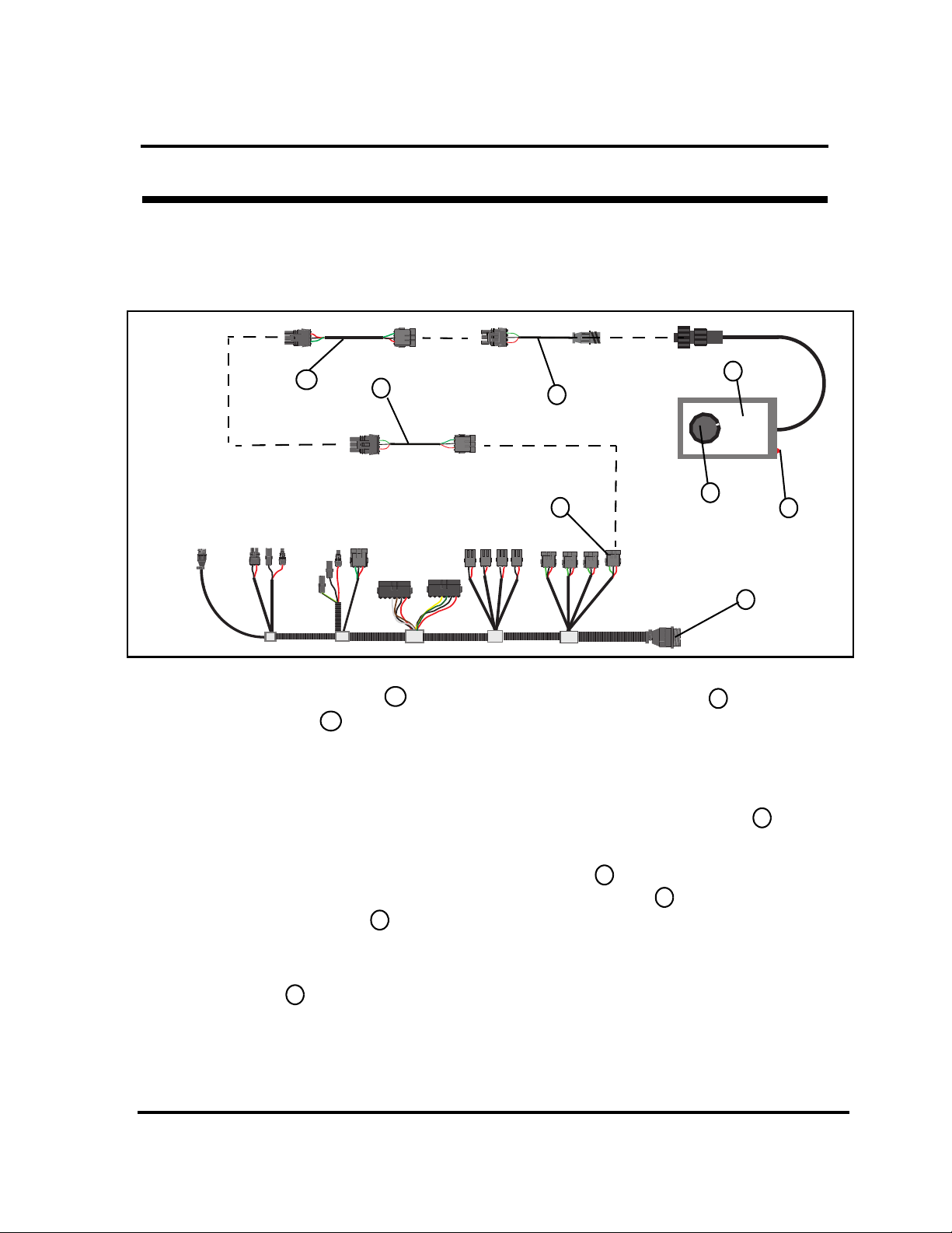
Pressure Sensor Simulator - for meter air pressure simulation on YP planters
The Pressure Sensor Simulator (part # AE6691) can be connected to the planter harness
and used to send a simulated air pressure sensor signal back to the monitor system.
Refer to Figure 12
Fig. 12
1. Locate the air pressure sensor in the air pressure assembly. On all planters, this is
6
7
mounted over the right wing.
2. Disconnect the Voltage to Frequency Converter from the sensor, and connect the Pressure
Sensor Simulator to the converter. The red LED light with indicate the presence of power
1
2
9
in the harness.
3. Rotating the knob on the face of the simulator clockwise will cause the output signal to
8
increase in voltage. Turning the knob counter-clockwise will cause the output signal to
decrease in voltage. Harness and monitor setup can be verified by observing the pressure
reading displayed on the work screen, or on the channel 2 diagnostics screen.
4. To send a simulate pressure signal from the extension harness or at the FDBK 2 lead, refer to
page 4 and assemble the components listed in step one. Connect this assembly at either
location and test as you normally would.
5. Observe the workscreen or the channel two diagnostic screen at the channel frequency filter reading.
If no signal is seen, check monitor setup. Also check connections at the extension harness, and at
the FDBK 2 connection of the actuator harness.
4
5
3
2/5/13 116-008M
Page 9

Great Plains Mfg., Inc. 9
AE6690
ACTUATOR
TEST BOX
SN: XXXXX
1
3
4
Diagnostic Kit Applications for Air Drills With IntelliAg
All functions of the Diagnostic Kit covered in the previous pages can also be performed on any
Great Plains Air Drill that has the DICKEY-john IntelliAg monitoring system.
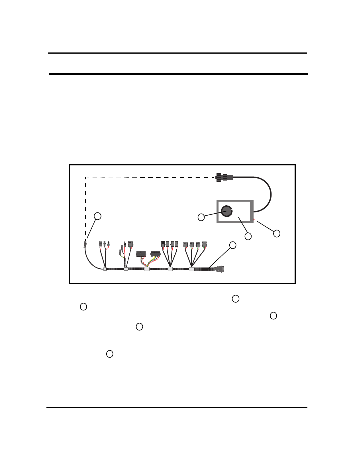
Actuator Test Box - for testing air drill linear actuators
The Actuator Test Box (part # AE6690) can be used on air drills that have the
variable rate linear actuators installed. The drill harness must be electrically connected to the tractor for the switchbox to function. If this is not possible, another
12VDC power supply needs to be connected to the tower connector of the test
box harness (connector with only two wires). Pin A of this connection is power
and pin B is ground.
Refer to Figure 12
1. Locate the harness coming out of the linear
actuator. Follow this harness until the
actuator driver is found. The actuator
2
3
driver has a second lead coming out of it that
2
5
6
leads to a six pin weather pack connector and
is connected to one of two mating connectors
on the working set master harness. If
4
working on a drill with two actuators, the
front driver should be connected to the plug
labeled “Front Zero”, and the rear driver
5
should be connected to the plug labeled
“Rear Zero”.
6
2. Disconnect the drivers’ six pin connector from
the working set master harness and install the
Actuator Test Box onto the now open plugs.
1
Fig. 12
3. The Actuator Test Box contains a spring centered momentary switch. Moving the switch to
one side or the other will cause the actuator to either extend or retract. When the switch is
released, it will re-center itself and stop actuator motion. DO NOT USE THIS TOOL AS A
REPLACEMENT FOR VARIABLE RATE CONTROL DURING SEEDING!
116-008M 2/5/13
Page 10

10 Great Plains Mfg., Inc.
Radar
Simulator
Power
AE6608
SN: XXXXX
MIN
MAX
5
3
4
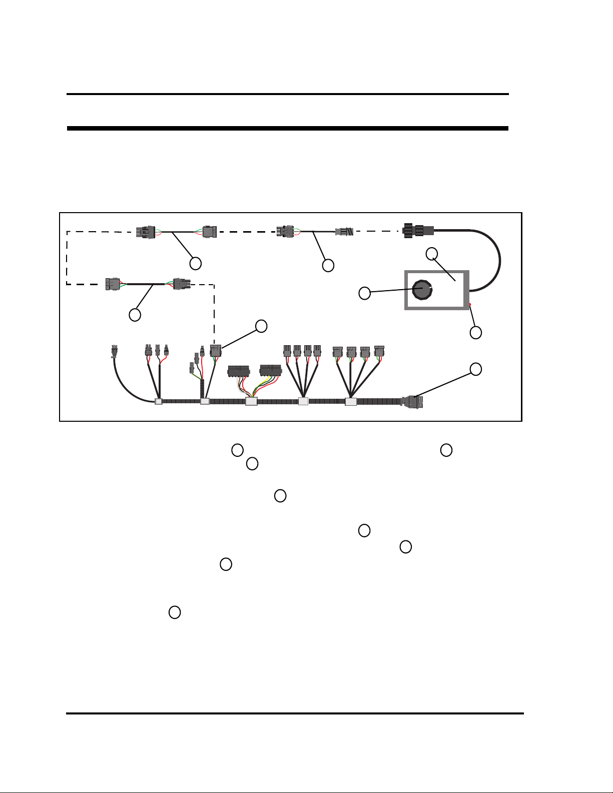
Radar Simulator - for ground speed simulation on air drills.
The Radar Simulator (part # AE6608) can be coupled with the Radar Sensor Adapter (part
# AE2609) and connected to the air cart harness to send a simulated speed pulse to the
monitor system.
Refer to Figure 13
1. Couple the Radar Simulator together with
the Radar Sensor Adapter.
2. Locate the hall effect or radar ground speed
sensor. On ADC2350/2350B carts, the sensor
is located inside the left wheel. On NTA607/
1
2
1
6
2
2007 drills the radar is located near the front of
the tongue. On NTA907/3007 drills, a rotary
application rate sensor is used for ground speed
and is located on the left hand ground drive
wheel.
Fig. 13
3. Follow the lead coming out of the ground speed sensor until you find the three pin
weatherpack connector. Disconnect the sensor lead from the monitor harness and connect
the assembly made in step one to the monitor harness. On NTA607/2007 drills there is an
extension harness between the radar and the monitor harness. This assembly can also
be connected at the working set master harness on the lead labeled “GND SPEED”.
4. Make sure the red LED light at the top of the simulator is brightly lit. This light
5
3
4
indicates a good power supply coming from the harness. If the light is off or dimly lit,
make sure the monitor system is powered on and inspect the harness and connections.
5. Rotating the knob on the face of the simulator changes the pulse rate that it outputs.
6
A clockwise rotation will speed the pulse rate up, and a counterclockwise rotation
slows the rate down.
6. Observe the ground speed reading on the work screen or on the diagnostic screen at the
frequency digital groundspeed. If no signal is seen, check the ground speed setup in the
monitor. Also check the connection at the ground speed connection at the actuator harness.
2/5/13 116-008M
Page 11

Great Plains Mfg., Inc. 11
Radar
Simulator
Power
AE6608
SN: XXXXX
MIN
MAX
7
6
Radar Simulator - for fan speed simulation on air drills
The Radar Simulator (part # AE6608) can be coupled with the Application Rate Sensor
Adapter (part # AE2607) and the Radar Sensor Adapter (part # AE2609) and connected to the
air drill harness for sending a simulated fan speed pulse to the monitor system.
Refer to Figure 14
3
4
5
2
8
Fig. 14
1
1. Assemble the Radar Simulator together with the Radar Sensor Adapter and the
Application Rate Sensor Adapter.
1
3
2
2. Locate the wiring harness coming out of the fan speed sensor and follow it until you find
the connection at the extension harness.
4
3. Disconnect the sensor lead from the extension harness and connect the assembly made in
step one. It can also be connected to the RPM sensor lead where the extension
harness connects to the working set master harness.
6
5
4. Make sure the red LED light at the top of the simulator is brightly lit. This light
7
indicates a good power supply coming from the harness. If the light is off or dimly lit,
make sure the monitor system is powered on and inspect the harness and connections.
5. Rotating the knob on the face of the simulator changes the pulse rate that in outputs.
8
A clockwise rotation will speed the pulse rate up, and a counterclockwise rotation
slows the rate down.
6. Observe the fan rpm reading on the work screen or on the diagnostic screen at the frequency
rpm reading. If no signal is seen, check fan rpm setup in the monitor. Also check the
extension harness and the RPM connection on the actuator harness.
116-008M 2/5/13
Page 12

12 Great Plains Mfg., Inc.
Radar
Simulator
Power
AE6608
SN: XXXXX
MIN
MAX
MODEL 46436-117B
SERIAL
XXXXX
e24
(360 COUNT APR)
02 0019
2010 03
5
6
7
Radar Simulator - for application rate sensor simulation on air drills.
The Radar Simulator The Radar Simulator (part # AE6608) can be coupled with the Radar
Sensor Adapter (part # AE2609) and the Application Rate Sensor Adapter (part # AE2607)and
connected to the air drill harness for sending a simulated application rate sensor pulse to the
monitor system.
Refer to Figure 15
3
2
4
9
8
1
Fig. 15
1. Assemble the Radar Simulator together with the Radar Sensor Adapter and the
Application Rate Sensor Adapter.
2. Locate the wiring harness coming out of the application rate sensor. On any air
1
2
3
4
drill, this will be found at the end of the meter shaft. Follow the lead until you find
the three pin connection at the working set master harness.
5
3. Disconnect the sensor from the working set master harness and connect the assembly
made in step one. It can be connected to the FRONT AP (Front meter shaft sensor)
or the REAR AP (Rear meter shaft sensor).
7
6
4. Make sure the red LED light at the top of the simulator is brightly lit. This light
8
indicates a good power supply coming from the harness. If the light is off or dimly lit,
make sure the monitor system is powered on and inspect the harness and connections.
5. Rotating the knob on the face of the simulator changes the pulse rate that in outputs.
9
A clockwise rotation will speed the pulse rate up, and a counterclockwise rotation
slows the rate down.
6. Observe the channel frequency pulse reading the channel 1 or 2 as it relates to the circuit
being tested on the diagnostic screen. If no signal is seen, check monitor setup. Also check
the extension harness and the connection at Front AP, or Rear AP.
2/5/13 116-008M
Page 13

Great Plains Mfg., Inc. 13
AgExpress Electronics
Sensor Tester
AE6602
S/N: XXXXX
MODEL 46436-117B
SERIAL
XXXXX
e24
(360 COUNT APR)
02 0019
2010 03
2
1
Sensor Tester - for blockage sensor testing on air drills.
The Sensor Tester (part # AE6602) is primarily used to verify the operation of the blockage sensors.
These are located in the smaller seed delivery hoses on or near the distribution towers.
Refer to Figure 16
1. Locate the row associated with the sensor
to be tested.
2. Locate the wiring harness coming out of the sensor and follow
it up to the row harness connection.
1
3. Connect the Seed Sensor Tester to the sensor lead. Any
2
object passing through the blockage sensor, will cause the
sensor to emit a pulse. With the tester connected to the sensor,
drop some seed or feed a flexible object like a zip tie through
the seed tube. If the sensor is working correctly, the pulse it
creates will cause the tester to “beep”.
Fig. 16
Note: The Seed Tube Sensor Tester operates on a 9 volt battery that is accessible through a door
in the back of the case. Make sure the battery is good before replacing a sensor.
Sensor Tester - for application rate sensor testing on air drills.
The Sensor Tester (part # AE6602) can be used in conjunction with the Application Rate
Sensor Adapter (part # AE2607) to verify the operation of the application rate sensor (shaft
speed sensor).
Refer to Figure 17
1. Assemble the Seed Sensor Tester together with the
Application Rate Sensor Tester Adapter.
2. Locate the wiring harness coming out of the application
rate sensor. On all air drills, this can be found mounted
3
on the end of the meter shaft. Follow the lead until you
find the three pin connection at the working set master
harness.
3. Disconnect the application rate sensor lead at the extension harness and connect the assembly
made in step one to the application rate sensor.
4. The application rate sensor will create 360 pulses per revolution of its input shaft. Every
pulse created will case the sensor tester to “beep” if the sensor is functioning properly.
Note: The Seed Tube Sensor Tester operates on a 9 volt battery that is accessible through a door
in the back of the case. Make sure the battery is good before replacing a sensor.
1
2
2
1
3
Fig. 17
116-008M 2/5/13
Page 14

14 Great Plains Mfg., Inc.
AgExpress Electronics
Sensor Tester
AE6602
S/N: XXXXX
AgExpress Electronics
Sensor Tester
AE6602
S/N: XXXXX
3
Sensor Tester - for testing ground speed sensors on ADC2350/2350B.
The Sensor Tester (part # AE6602) can be used in conjunction with the Application Rate
Sensor Adapter (part # AE2607) to verify the operation of the ground speed sensor.
Refer to Figure 18
1. Assemble the Sensor Tester together with the Application Rate
Sensor Adapter.
2
2. Locate the hall effect sensor that supplies the speed signal to
1
3
2
3
the monitoring system.
3. Follow the wiring harness that comes out of the
ground speed sensor until you find where it connects to the monitor harness. Disconnect the
sensor from the harness and connect the assembly made in step one to the sensor lead.
1
Fig. 18
4. When testing a hall effect sensor, wave a screwdriver or other metallic object past the end
of it. Every time the object passes the end of the sensor, it should create a pulse. This
pulse will cause the sensor tester to “beep”.
Note: The Seed Tube Sensor Tester operates on a 9 volt battery that is accessible through a door
in the back of the case. Make sure the battery is good before replacing a sensor.
Sensor Tester - for testing ground speed sensors on NTA2007/607.
The Sensor Tester (part # AE6602) can be used in conjunction with the Radar Sensor Adapter
(part # AE2609) to verify the operation of the radar.
Refer to Figure 19
1. Assemble the Sensor Tester together with the Radar Sensor
Adapter.
2
2. Locate the radar sensor that is located near the front of
the tongue.
3. Follow the wiring harness that comes out of the
ground speed sensor until you find where it connects to the monitor
harness. Disconnect the sensor from the harness and connect the assembly
1
3
2
1
Fig. 19
4. When testing a radar sensor, wave your hand or other solid object past the end of it. Every
time the sensor sees motion, it should create a pulse. This pulse will cause the sensor tester
to “beep”.
Note: The Seed Tube Sensor Tester operates on a 9 volt battery that is accessible through a door
in the back of the case. Make sure the battery is good before replacing a sensor.
2/5/13 116-008M
Page 15

Great Plains Mfg., Inc. 15
AgExpress Electronics
Sensor Tester
AE6602
S/N: XXXXX
MODEL 46436-117B
SERIAL
XXXXX
e24
(360 COUNT APR)
02 0019
2010 03
AgExpress Electronics
Sensor Tester
AE6602
S/N: XXXXX
Sensor Tester - for testing ground speed sensors on NTA3007/907.
The Sensor Tester (part # AE6602) can be used in conjunction with the Application Rate
Sensor Adapter (part # AE2607) to verify the operation of the ground speed sensor on
NTA3007/907 air drills.
Refer to Figure 20
1. Assemble the Seed Sensor Tester together with the
Application Rate Sensor Tester Adapter.
1
2
1
2
2. Locate the wiring harness coming out of the ground speed
sensor. On NTA3007/907 drills, this can be found on the
3
3
end of the small ground drive wheel on the left hand side.
Follow the lead until you find the three pin connection at
the working set master harness.
Fig. 20
3. Disconnect the sensor lead from the harness and connect the assembly
made in step one to the sensor.
4. This ground speed sensor will create 360 pulses per revolution of its input shaft. Every
pulse created will case the sensor tester to “beep” if the sensor is functioning properly.
Note: The Seed Tube Sensor Tester operates on a 9 volt battery that is accessible through a door
in the back of the case. Make sure the battery is good before replacing a sensor.
Sensor Tester - for testing fan speed sensors on air drills.
The Sensor Tester (part # AE6602) can be used in conjunction with the Application Rate Sensor
Adapter (part # AE2607) to verify the operation of the hall effect fan speed sensor.
Refer to Figure 21
1. Assemble the Sensor Tester together with the
Application Rate Sensor Adapter.
2. Locate the hall effect sensor the supplies the fan speed
1
2
2
3
1
3
signal to the monitoring system. This will be the wiring
harness coming out of the screen on the fan assembly.
Fig. 21
3. Follow the harness until it connect to the monitor harness. Disconnect the harness and
connect the assembly made in step one to the sensor lead.
4. If the sensor is still mounted in the fan assembly, any motion of the fan should cause the
sensor to create a pulse that will make the tester “beep”. If the sensor has been removed,
waving a metallic object like a screwdriver should produce the same result.
Note: The Seed Tube Sensor Tester operates on a 9 volt battery that is accessible through a door
in the back of the case. Make sure the battery is good before replacing a sensor.
116-008M 2/5/13
Page 16

16 Great Plains Mfg., Inc.
AgExpres s Electro nics
Sensor Tester
AE6602
S/N: XXXXX
SN: XXXXX
AE6691
Pessure Sensor
Simulator
6
Radar
Simulator
Power
AE6608
SN: XXXXX
MIN
MAX
AE6690
ACTUATOR
TEST BOX
SN: XXXXX
1
Appendix
Parts List
Refer to Figure 22
Diagnostic Kit Contents
823-401C Great Plains Diagnostic Kit
Callout Quantity Part Number Description
1 1 AE6690 Actuator Test Box
2 1 AE6602 Sensor Tester
3 1 AE6608 Radar Simulator
4 1 AE2609 Radar Sensor Adapter
5 1 AE2607 Application Rate Sensor Adapter
6 1 AE6691 Pressure Sensor Simulator
7 1 AE7843 Case
3
2
4
6
Fig. 22
2/5/13 116-008M
Great Plains Manufacturing, Inc.
Corporate Office P.O. Box 5060
 Loading...