

Page 1
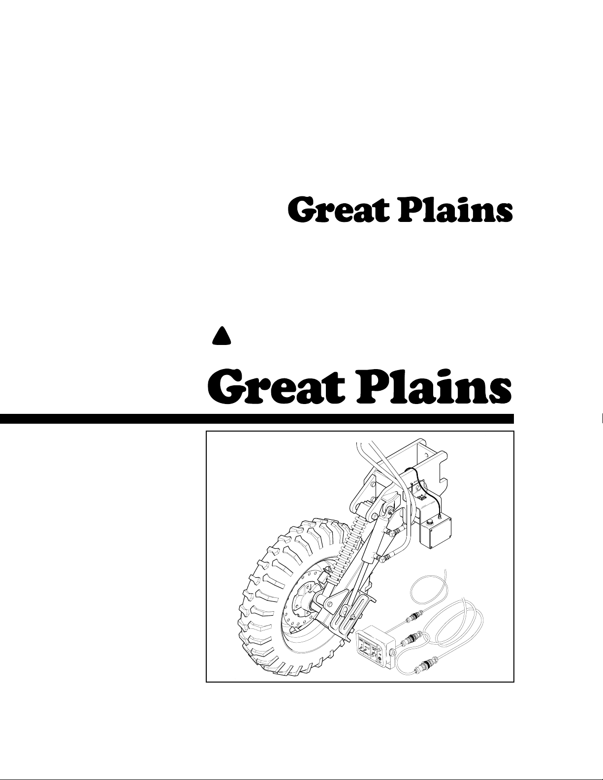
Operator’s Manual
PH-15, PH-20, PFH-15 and PFH-20
Coulter Command System
Manufacturing, Inc.
P.O. Box 5060 ● Salina, Kansas 67402-5060
Read the operator’s manual entirely. When you see this symbol, the subsequent in-
!
structions and warnings are serious- follow without exception. Your life and the lives of
others depend on it!
© Copyright 2000 Printed
5/31/2001
12611
Cover illustration may show optional equipment not supplied with standard unit.
148-384M
Page 2

Table of Contents
Table of Contents
Great Plains Mfg., Inc.
Important Safety Information . . . . . . . . . . . . .1
Introduction . . . . . . . . . . . . . . . . . . . . . . . . . . .4
Description of Unit. . . . . . . . . . . . . . . . . . . .4
Using This Manual. . . . . . . . . . . . . . . . . . . .4
Definitions . . . . . . . . . . . . . . . . . . . . . . .4
Owner Assistance . . . . . . . . . . . . . . . . . . . .4
Section 1 Assembly and Setup. . . . . . . . . . . .5
Prestart Checklist . . . . . . . . . . . . . . . . . . . .5
Depth Sensing Wheel . . . . . . . . . . . . . . . . .5
Sensor Box . . . . . . . . . . . . . . . . . . . . . .6
Gauge Wheel Lift Cylinder . . . . . . . . . .7
Speed Sensor . . . . . . . . . . . . . . . . . . . .7
Lift Switch . . . . . . . . . . . . . . . . . . . . . . .8
Wiring Harness . . . . . . . . . . . . . . . . . . .8
Tongue Cylinder . . . . . . . . . . . . . . . . . .9
Hydraulic Control Valve. . . . . . . . . . . .10
Hydraulic Connections . . . . . . . . . . . .11
Control Box . . . . . . . . . . . . . . . . . . . . .12
Sensor Box Adjustments. . . . . . . . . . . . . .13
Section 2 Operating Instructions . . . . . . . . .14
Load Sensing Hydraulics . . . . . . . . . . . . . 14
Hydraulic Hook-Up & Function. . . . . . . . . 14
Operation of Electronic Controls. . . . . . . . 15
Field Adjustments. . . . . . . . . . . . . . . . . . . 16
Lift Switch. . . . . . . . . . . . . . . . . . . . . . 16
Speed Sensor . . . . . . . . . . . . . . . . . . 17
Hydraulic Valve . . . . . . . . . . . . . . . . . 17
Section 3 Troubleshooting. . . . . . . . . . . . . . 18
System Schematics . . . . . . . . . . . . . . . . . 20
Hydraulic Schematic . . . . . . . . . . . . . 20
Electrical Schematic. . . . . . . . . . . . . . 21
Section 4 Maintenance & Lubrication. . . . . 22
Maintenance. . . . . . . . . . . . . . . . . . . . . . . 22
Lubrication . . . . . . . . . . . . . . . . . . . . . . . . 22
Depth Sensing Arm Wheel Pivot . . . . . . . 22
Axle Bearings . . . . . . . . . . . . . . . . . . . . . . 22
Appendix . . . . . . . . . . . . . . . . . . . . . . . . . . . . 23
Torque Values Chart. . . . . . . . . . . . . . . . . 23
© Copyright 2000 All rights Reserved
Great Plains Manufacturing, Inc. provides this publication “as is” without warranty of any kind, either expressed or implied. While every precaution has been taken in the preparation
of this manual, Great Plains Manufacturing, Inc. assumes no responsibility for errors or omissions. Neither is any liability assumed for damages resulting from the use of the information contained herein. Great Plains Manufacturing, Inc. reserves the right to revise and improve its products as it sees fit. This publication describes the state of this product at the
time of its publication,and may not reflect the product in the future.
The following are trademarks of Great Plains Mfg., Inc.: Application Systems, Ausherman, Land Pride, Great Plains, Seed-Lok
All other brands and product names are trademarks or registered trademarks of their respective holders.
PH-15, PH-20, PFH-15 and PFH-20 Coulter Command System 148-384M 6/21/2004
Great Plains Manufacturing, Incorporated T r ademarks
Printed in the United States of America.
Page 3
Great Plains Mfg., Inc.
Important Safety Information
Important Safety Information
Look for Safety Symbol
The SAFETY ALERT SYMBOL indicates there is a potential hazard to
personal safety involved and extra
safety precaution must be taken.
When you see this symbol, be alert
and carefully read the message that
follows it. In addition to design and
configuration of equipment, hazard
control and accident prevention are
dependent upon the awareness,concern, prudence and proper training of
personnel involved in the operation,
transport, maintenance and storage
of equipment.
!
Be Aware of Signal Words
Signal words designate a degree or
level of hazard seriousness. The signal words are:
!
DANGER
Indicates an imminently hazardous
situation which, if not avoided, will
result in death or serious injury. This
signal word is limited to the most
extreme situations, typically for
machine components that, for functional purposes, cannot be guarded.
!
WARNING
Indicates a potentially hazardous situation which, if not avoided, could
result in death or serious injury, and
includes hazards that are exposed
when guards are removed. It may
also be used to alert against unsafe
practices.
!
CAUTION
Indicates a potentially hazardous situation which, if not avoided, may
result in minor or moderate injury. It
may also be used to alert against
unsafe practices.
Keep Riders
Off Machinery
Riders obstruct the operator’s view.
Riders could be struck by foreign
objects or thrown from machine.
▲ Never allow riders on implement.
▲ Never allow children to operate
equipment.
For Your Protection
▲ Thoroughly read and understand
Safety Decals, page 4. Read all
instructions noted on decals.
OFF
Shutdown and Storage
▲ Lower machine to ground, put
tractor in park, turn off engine,
and remove key.
▲ Detach and store implement in an
area where children normally do
not play. Secure implement with
blocks and supports.
Handle
Chemicals Properly
Agricultural chemicals can be dangerous. Improper use can seriously
injure persons, animals, plants, soil
and property.
▲ Wear protective clothing.
▲ Handle all chemicals with care.
▲ Follow instructions on container
label.
▲ Avoid inhaling smoke from any
type of chemical fire.
▲ Store or dispose of unused chem-
icals as specified by chemical
manufacturer.
6/21/2004
PH-15, PH-20, PFH-15 and PFH-20 Coulter Command System 148-384M
1
Page 4
Important Safety Information
Great Plains Mfg., Inc.
Use Safety
Lights and Devices
Slow-moving tractors, self-propelled
equipment and towed implements
can create a hazard when driven on
public roads. They are difficult to see,
especially at night.
▲ Use flashing warning lights and
turn signals whenever driving on
public roads.
▲ Use lights and devices provided
with implement.
Transport
Machinery Safely
Maximum transport speed for implement is 20 mph. Some rough terrains
require a slower speed. Sudden
braking can cause a towed load to
swerve and upset.
▲ Do not exceed 20 mph. Never
travel at a speed which does not
allow adequate control of steering
and stopping. Reduce speed if
towed load is not equipped with
brakes.
▲ Comply with state and local laws.
▲ Do not tow an implement that,
when fully loaded, weighs more
than 1.5 times the weight of towing vehicle.
Use A Safety Chain
▲ Use a safety chain to help con-
trol drawn machinery should it
separate from tractor drawbar.
▲ Use a chain with a strength rat-
ing equal to or greater than the
gross weight of towed machinery.
▲ Attach chain to tractor drawbar
support or other specified
anchor location. Allow only
enough slack in chain to permit
turning.
▲ Replace chain if any links or end
fittings are broken, stretched or
damaged.
▲ Do not use safety
chain for towing.
Practice Safe Maintenance
▲ Understand procedure before
doing work. Use proper tools and
equipment. Refer to this manual
for additional information.
▲ Work in a clean, dry area.
▲ Lower implement to ground, put
tractor in park, turn off engine,
and remove key before performing
maintenance.
▲ Allow implement to cool completely.
▲ Inspect all parts. Make sure parts
are in good condition and installed
properly.
▲ Remove buildup of grease, oil or
debris.
▲ Remove all tools and unused
parts from implement before operation.
PH-15, PH-20, PFH-15 and PFH-20 Coulter Command System 148-384M 6/21/2004
2
Page 5
Great Plains Mfg., Inc.
Important Safety Information
Prepare for Emergencies
▲ Be prepared if a fire starts.
▲ Keep a first aid kit and fire extin-
guisher handy.
▲ Keep emergency numbers for
doctor, ambulance, hospital and
fire department near phone.
911
Wear
Protective Equipment
▲ Wear protective clothing and
equipment.
▲ Wear clothing and equipment
appropriate for the job. Avoid
loose-fitting clothing.
▲ Because prolonged exposure to
loud noise can cause hearing
impairment or hearing loss, wear
suitable hearing protection such
as earmuffs or earplugs.
▲ Because operating equipment
safely requires your full attention,
avoid wearing radio headphones
while operating machinery.
Avoid High
Pressure Fluids Hazard
Escaping fluid under pressure can
penetrate skin, causing serious
injury.
▲ Avoid the hazard by relieving
pressure before disconnecting
hydraulic lines.
▲ Use a piece of paper or card-
board, NOT BODY PARTS, to
check for suspected leaks.
▲ Wear protective gloves and safety
glasses or goggles when working
with hydraulic systems.
▲ If an accident occurs, see a doc-
tor immediately. Any fluid injected
into the skin must be surgically
removed within a few hours or
gangrene may result.
Safety at All Times
Thoroughly read and understand this
manual before operating implement.
Refer to Safety Decals, page 4. Read
all instructions noted on decals.
▲ Be familiar with all implement
functions.
▲ Operate implement from driver’s
seat only.
▲ Do not leave tractor or implement
unattended with engine running.
▲ Do not dismount a moving tractor.
Dismounting a moving tractor could
cause serious injury or death.
▲ Do not stand between the tractor
and implement during hitching.
▲ Keep hands, feet and clothing
away from power-driven parts.
▲ Wear snug-fitting clothing to avoid
entanglement with moving parts.
▲ Watch out for wires, trees, etc.,
when raising implement. Make
sure all persons are clear of working area.
▲ Do not turn tractor too tight, caus-
ing implement to ride up on
wheels.
Tire Safety
Tire changing can be dangerous and
should be performed by trained personnel using correct tools and equipment.
▲ When inflating tires, use a clip-on
chuck and extension hose long
enough to allow you to stand to
one side–not in front of or over tire
assembly. Use a safety cage if
available.
▲ When removing and installing
wheels, use wheel-handling
equipment adequate for weight
involved.
6/21/2004
PH-15, PH-20, PFH-15 and PFH-20 Coulter Command System 148-384M
3
Page 6

Introduction
Introduction
Great Plains Mfg., Inc.
Great Plains welcomes you to its growing family of new
product owners. This implement has been designed with
care and built by skilled workersusing quality materials.
Proper setup, maintenance and safe operating practices
will help you get years of satisfactory use from the machine.
Description of Unit
The Precision Hitch Coulter CommandSystem couplesa
microprocessor with electro-hydraulicsto provide a stateof-the-art system for maintaining coulter depthregardless
of the terrain or soil type. It also provides coulter depth adjustment from the tractor cab.
The Coulter Command System contains a depth sensing
wheel, an electronic control box, a speed sensor, a depth
sensorbox,a lift controlswitch,a wiring harness, atop link
and a hydrauliccontrol valve. It uses the tongue cylinder
from your Precision Hitch.
This manual applies to the following:
• 148-382A Precision Hitch Coulter Command,
Non Fertilizer
• 148-383A Precision Hitch Coulter Command, For
Fertilizer
Referto the Precision Hitchoperator’s manualfor detailed
informationonsafelyoperating,adjusting, troubleshooting
and maintaining the Precision Hitch. Refer to the parts
manual for Coulter Command part identification.
• 148-365M PH-15, PH-20, PFH-15 and PFH-20
Operator’s Manual
• 148-365P PH-15, PH-20, PFH-15 and PFH-20
Parts Manual
Owner Assistance
If you need customer service or repair parts, contact a
Great Plains dealer.They have trained personnel, repair
parts and equipment specially designed for Great Plains
products.
Your machine’sparts were specially designed and should
only be replaced with Great Plains parts. Always use the
serial and model number when ordering parts from your
Great Plains dealer.
Your Great Plains dealer wants youto be satisfied with
your new machine. If you do not understand any part of
this manual or are not satisfied with the service received,
please take the following actions.
1. Discuss the matter with your dealershipservice manager.Make sure they are aware of anyproblems so
they can assist you.
2. If you are still unsatisfied, seek out the owner or general manager of the dealership.
3. For further assistance write to:
Product Support
Great Plains Mfg. Inc., Service Department
PO Box 5060
Salina, KS 67402-5060
Using This Manual
This manual will familiarize you with safety, assembly, operation, adjustments, troubleshooting and maintenance.
Readthis manualand followthe recommendationsto help
ensure safe and efficient operation.
Theinformation in this manual iscurrent at printing. Some
parts maychange to assure top performance.
Definitions
The following terms are used throughout this manual.
Right-handand left-hand as used in thismanual are deter-
mined by facing the direction the machinewill travel while
in use unless otherwise stated.
IMPORTANT: A crucial point of information related to
the preceding topic. For safe and correct oper ation,
read and follow the directions provided before continuing.
NOTE: Useful information related to the preceding topic.
PH-15, PH-20, PFH-15 and PFH-20 Coulter Command System 148-384M 6/21/2004
4
Page 7
Great Plains Mfg., Inc.
Section 1 Assembly and Setup
Section 1 Assembly and Setup
Prestart Checklist
Check
All major frame components
Fasteners and pins that were shipped with the Coulter Command System.
NOTE: All hardware from the factory has been installed in the
location where it will be used. If a part or fastener is temporarily
removed for assembly reasons, remember where it goes.Keep
the parts separated.
Have a minimum of 2 people at hand while assembling the
Coulter Command System.
Have a forklift or loader along with chains and safety stands
ready for the assembly task.
If you are unsure where a fastener is used, refer to the Parts
Manual to identify it.
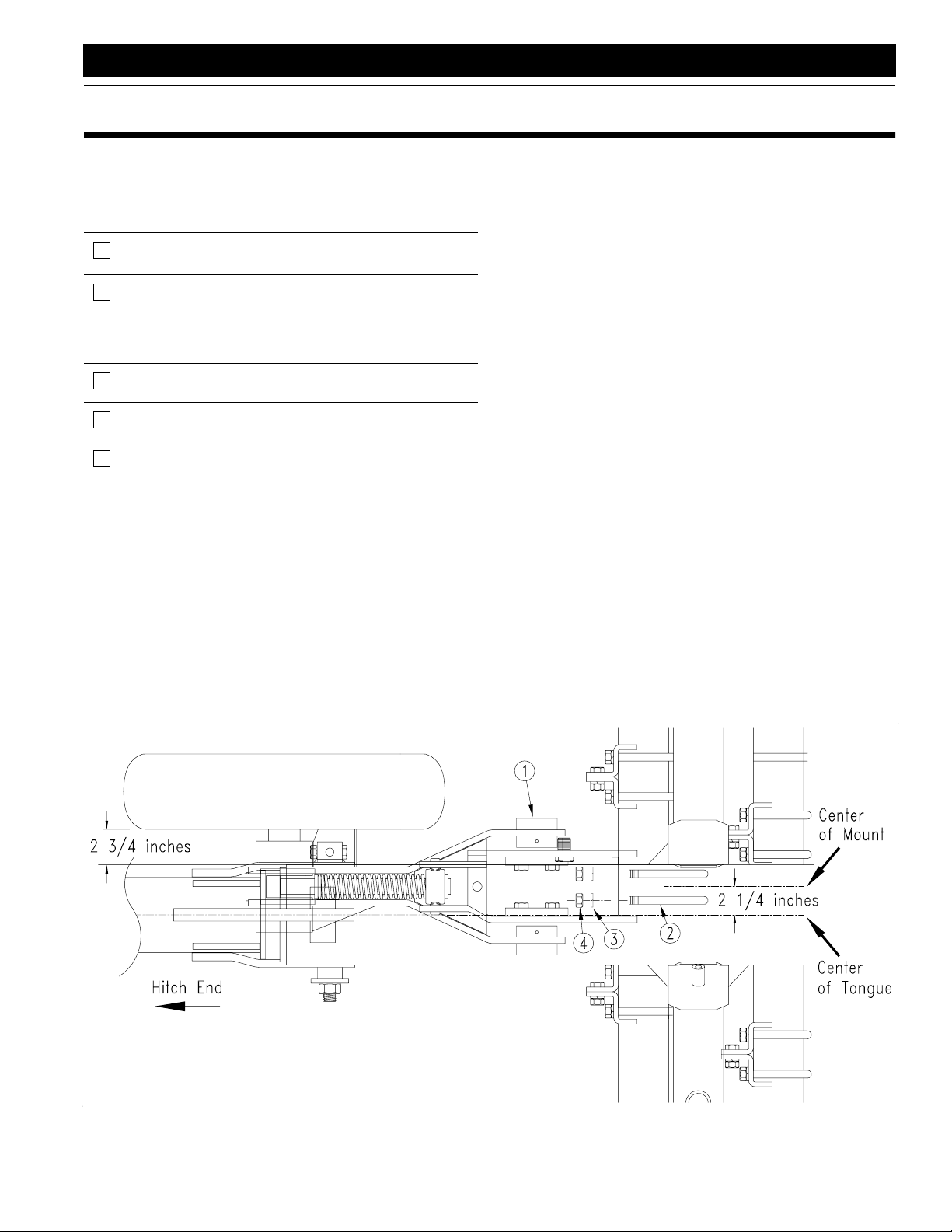
Depth Sensing Wheel
If your Precision Hitch is equipped with liquid fertilizer
(PFH), the fertilizer drive wheel doubles as the coulter
depth sensing wheel and will require additional sensor assembly and adjustment.
If you do not have the liquid fertilizer option (PFH), the
coulter command will contain a coulter depth sensing
wheel which is subassembled and preadjusted.
See Figure 1-1.
Installthe coulter depthsensing wheel assembly(1) to the
front 4” x 4” coulter tool bar tube with the two 5/8 x 6 inch
u-bolts (2), lock washers (3) and nuts (4).
Position the center of the coulter depth sensing wheel
mount bracket2 1/4 inches to the rightof the centerof the
Precision Hitch beam. This will leave about 2 3/4 inch
clearancebetweenthe inside ofthe depthsensing tireand
the edge of the hitch center beam.
6/21/2004
Figure 1-1
Depth Sensing Wheel
PH-15, PH-20, PFH-15 and PFH-20 Coulter Command System 148-384M
18439
5
Page 8
Section 1 Assembly and Setup
Great Plains Mfg., Inc.
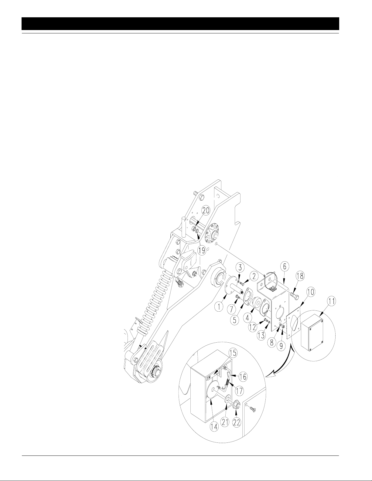
Sensor Box
Ifthe sensor boxisnot preassembledto the depthsensing
wheel, refer to Figure 1-2 and the following instructions.
1. Assemble sensor spindle (1) to left end of fertilizer
drivewheel rockshaftwith three1/4 x3/4 inch bolts(2)
and lock washers(3).
2. Bolt the bearing (4) betweentwo flangettes (5) andto
theback side of thesensor mount plate (6) with5/16 x
3/4 inch carriage bolts (7), lock washers (8) and nuts
(9). Do not tighten nuts at this time.
NOTE: Position the heads of the bolts against the
flangettes with lock washers and nuts pointing outward.
Locking collar on bearing should point away from the sensor mount plate and toward the coulter depth sensing
wheel.
3. Place rubber gasket (10) between sensor box (11)
and the sensor mount plate (6). Screw sensor box to
sensor mount plate with #10 x 7/16 inch pan head
screws (12) and star lock washers(13).
4. Remove cover from sensor box and inspect the internal linkages.The circular disk (14) should be linked to
the flat bar (15) with a formed round bar link (16).
Make sure the round bar link is in place and secured
witha spring clip extensionspring(17) that is connected between the circular disk and the flat bar through
the small holes.
5. Slide bearing and sensor mount plate subassembly
oversensorspindle(1), andbolt sensormountplate to
drive wheel mount bracket with 1/2 x 1 1/2 inch bolts
(18), lock washers(19) and nuts (20).
6. Place circular disk (13) over threaded end of sensor
spindle (1) and install a 3/8 inch washer (21) and
flange nut (22). Do not tighten flange nut at this time.
7. With the circular disk inplace, slide the sensormount
plate subassembly in or out until the vertical flat bar
link (15) and the circular disk are aligned.
8. Tighten two set screws on the bearing (4) to hold the
subassembly in place.
9. Tighten the flangette bolts (7) being careful not to
damage the internal linkages.
10. Set sensor box cover and cover screws aside and
continue with speed sensor assembly.
Figure 1-2
Sensor Box
PH-15, PH-20, PFH-15 and PFH-20 Coulter Command System 148-384M 6/21/2004
6
18427
Page 9

Great Plains Mfg., Inc.
Section 1 Assembly and Setup
Gauge Wheel Lift Cylinder
Refer to Figure 1-3.
1. Install the base end of the lift cylinder (1) to gauge
wheel mount bracket with a 1/2 x 1 3/4 inch clevis pin
(2) anda 1/8 x 3/4 inch cotter pin (3) provided with the
cylinder.
NOTE: The ports on the cylinder should point away from
the depth sensing gauge wheel.
2. Place the rod end of the lift cylinder between the slotted lugs on the gauge wheel arm. Place a flat washer
(4) on the outside of each slotted lug on the gauge
wheel arm. Pin in place with a 1 1/2 x 2 3/4 inch clevis
pin (5) and a 1/8 x 3/4 inch cotter pin (3).
Speed Sensor
Refer to Figure 1-4.
1. Removethetire and rimfrom the depthsensing wheel
andbolt thespeed sensorplate (1)between thewheel
and rim.
2. Screw the speed sensor (2) to the sensor mounting
bracket at bottom of the gauge wheel with #6 x 1/2
inch pan head screws (3), lock washers (4) and flat
washers (5).
3. Position sensor to just touch the speed sensor plate
(1) and tighten screws.
4. Route co-axial cable (6) from sensor, across gauge
wheel arms, and up the side opposite the tire.
5. Screwtheend fittinginto the co-axconnector ontop of
the sensor box(7).
6. Slide co-axial cable into notches at the bottom of
gauge wheel arms and fastento the side of gauge
wheel arm with the cabletie mounts (8) and cable ties
(9). Make sure the cable does not rub anything as
depth sensing wheel moves up and down.
Figure 1-3
Gauge Wheel Lift Cylinder
18428
6/21/2004
Figure 1-4
Gauge Wheel Lift Cylinder
PH-15, PH-20, PFH-15 and PFH-20 Coulter Command System 148-384M
18429
7
Page 10

Section 1 Assembly and Setup
Great Plains Mfg., Inc.
Lift Switch
Refer to Figure 1-5.
1. Bolt the plunger activated lift switch(1) to the switch
mount located nextto the left transport lift cylinder at
rear of the Precision Hitch transport frame with two
#10 x 3/4 inch pan head screws (2), flat washers (3),
lockwashers(4) andnuts (5).Do not tightenscrews at
this time.
2. Fastenrockshaftswitch cam (6)to transport rockshaft
just below the lift switch. Position the cam so it contacts the lift switch when hitch is raised and moves
awayfrom the lift switch when hitch is lowered. Position the worm gear screwon the cam mounting band
to the bottom of the rockshaft so it does not interfere
with the lift switch.
3. Adjust lift switch in the slotted holes so the plunger
movesin about1/8 inch when the camactivates itand
tighten the#10 screws. Do not bottom out the plunger
on the lift switch.
4. Rotate the cam assembly so it hits the plunger when
the hitch is raised just enough to begin to pick the
openers off the ground.
Wiring Harness
Refer to Figure 1-5.
1. Route the wiring harness (7) through 8 x 8 inch hitch
tube and to the lift switch at the rear of the machine.
Plug into the lift switch and support the cable with cable tie mounts (8) and cableties (9) or strapthe cable
to the hydraulichoses.
2. Plug the 4-pin connectorof the wiring harness tosensor box on the depth sensing wheel and support the
cable with cablemounts and ties.
3. Route the 9-pin connector through the spring hose
loop and to the tractor hitch. This will plug into the 9pin female connector from the control box extension
cable.
4. Plugthe otherthree short leadsinto theleads fromthe
solenoids on the hydraulic control valves (10 and 11)
after they are installed.
Figure 1-5
Lift Switch and Wiring Harness
PH-15, PH-20, PFH-15 and PFH-20 Coulter Command System 148-384M 6/21/2004
8
18430
Page 11

Great Plains Mfg., Inc.
Section 1 Assembly and Setup
Tongue Cylinder
Refer to Figure 1-6.
1. Removestroke pointer gauge (1) at the rod end of the
tongue cylinder. Retorque cylinder tie rod bolts to 95
ft-lbs.
2. Remove stroke pointer (2) at cylinder rod clevis.
3. Turn tonguecylinder withrodend pointingforwardand
down and with ports turned up. Use clevis pin (3),flat
washer (4) and cotter pin (5)to replacestroke pointer
pin at what is now the base end of the cylinder.
4. Connect rod end to tongue with clevis pin (6) and hair
pin cotter (7).
5. Remove elbow fitting (8) at base end of tongue cylinder and screw the 1/16inch orifice plate (9) into base
end port. Screw orifice plate in far enough so it does
not interfere with elbow fitting.
6. Replace fitting.
IMPORTANT: Failureto install the orifice platewill not allow Coulter Command to operate correctly.
6/21/2004
Figure 1-6
Tongue Cylinder
18432
PH-15, PH-20, PFH-15 and PFH-20 Coulter Command System 148-384M
9
Page 12

Section 1 Assembly and Setup
Hydraulic Control Valve
Refer to Figure 1-7.
1. Bolt the electronic depth control valve (1) to the top of
thevalvemount bracket(2)with 5/16x 4 inchbolts (3),
lock washers (4) and hex nuts (5). Position valve so
solenoids set abovethe middle of the top surface of
valve mount.
2. Bolt the lift circuit manifold (6) to the side of the valve
mount bracket with 5/16 x 4 inch bolts (7), lock washers (4) and hex nuts (5). Position valveso the four
ports pointawayfromvalvemountandsolenoid points
up.
3. Attach the valve mount to the Precision Hitch with 1/2
x 5 1/2 inch bolt (8), lock washer (9) and hex nut (10).
Assemble the bolt through the pivot tube (11) located
behind the tongue cylinder. Position valve mount so
dual solenoids facetoward rear of machine.
Great Plains Mfg., Inc.
Figure 1-7
Hydraulic Control Valve
PH-15, PH-20, PFH-15 and PFH-20 Coulter Command System 148-384M 6/21/2004
10
19361
Page 13

Great Plains Mfg., Inc.
Section 1 Assembly and Setup
Hydraulic Connections
Refer to Figure 1-8.
1. On the top valve assemblethe 3/4elbows (1) to valve
ports marked“P” and “T”and the3/4 straight adapters
(2) to valve ports marked “A” and “B”.
2. Onthe lower valveassemblethe 3/4 straightadapters
(2) to valveports marked “V1” and “V2” and the 3/4 elbows (1) to valve ports marked “C3” and “C4”.
3. Assemble the 9/16 elbows (3) to valve ports marked
“C1” and “C2” of the lower valve.
4. Assemble the remaining two 9/16 elbows (3) to the
ports on the side of the gauge wheel lift cylinder (4).
5. Removehoses(5)from tonguecylinder andassemble
them to the elbows at parts “P” and “T” on the top
valve.
6. Connect the 20inch long hose (6) between port “B”of
the top valve and the tongue cylinder base end fitting.
7. Connect the 30inch long hose (7) between port “A”of
the top valve and the tongue cylinder rod end fitting.
8. Remove hoses (8) from the front side of the relief
valve(9) which is mounted on the tongue tube andassemble them to the elbows at ports “C3” and “C4” on
the lower valve.
NOTE: The hose coming from the base end of the transport lift cylinders connects to port “C3”. The hose coming
from the rod end of the transport lift cylindersconnects to
port “C4”.
9. Connect a 36 inch long hose (10) to port “C1” of the
lower valve and the elbow on the base end of the
gauge wheel lift cylinder.
10. Connect a 36 inch long hose (10) to port “C2” of the
lowervalveand the elbow onthe rod end of thegauge
wheel lift cylinder.
11. Removethe plug from the top of the lowervalveat the
port labeled “M4” and replace it with the relief cartridge (11). Torque the cartridge to 30 ft-lbs.
12. Removethe reliefvalve andmount (9) which ismounted to the tongue tube by removing the 3/8 inch u-bolt.
Discard the relief valve and its mount.
13. Route the three wiring harness leads, mentioned on
page 8, step 4, under the valve mount.
14. Plug lead “A” into solenoid “A”.
15. Plug lead “B” into solenoid “B”.
16. Plug lead “S1” into solenoid “S1”.
6/21/2004
Figure 1-8
Hydraulic Connections
PH-15, PH-20, PFH-15 and PFH-20 Coulter Command System 148-384M
19360
11
Page 14

Section 1 Assembly and Setup
Control Box
1. Mount the control box, Figure 1-9, at a convenient locationin the tractorcab. Connectthe 12’ extensioncable to the 9-pin connector on the back of the control
box and route the cable back toward the tractor drawbar area making sure it willnot get kinkedor pinched.
2. Connect the power cord to a good uninterrupted 12
voltpowersourceonthe tractor.Connecting directlyto
the battery is recommended. Plug the cord into the
lead with the 2-Pin connector on the back of the control box. The polarity of the power supply is very important to prevent circuit damage. The white wire of
the power cord must be connected to the "+" positive
battery terminal andthe black wire to the "-" negative
battery terminal.
Great Plains Mfg., Inc.
Figure 1-9
Control Box
PH-15, PH-20, PFH-15 and PFH-20 Coulter Command System 148-384M 6/21/2004
12
12575
Page 15

Great Plains Mfg., Inc.
Section 1 Assembly and Setup
Sensor Box Adjustments
Refer to Figure 1-10.
Coulter commanddepth sensing wheel assemblies which
are preassembled at the factory are preadjusted and
should not require further adjustment. If the sensor box at
the depth sensing wheel has been field installed, or if its
linkage gets out of adjustment, it must be adjusted using
one of the following two procedures:
1. The best and most accuratemeans of adjusting the
linkage inside the sensor box makes use of a voltmeter which reads 0-12 voltsDC. The Control Box in the
tractormust be properly connected to a powersource
and the POWERswitch must be ON. The TONGUE
HYDRAULICS switch should be in the MANUAL
mode. The wiring harness must be connected to the
control box and the sensor box.The depth sensing
wheel should be off the ground with the arm rotated
down as far as its spring-loaded down-pressure link
will allow.Remove the cover from the sensorbox and
inspect the internal linkage for proper assembly as
shown in Figure 1-10.
With the depth sensing wheel in the max down position,the voltagepotential betweenthe lead containing
theWHITEWIRE andthe groundlead (BLACKWIRE)
in the gauge wheel sensor box(#1) should be 5 volts
DC plus or minus 1/4 volt. To adjust the gauge wheel
sensor boxlinkage, loosen the 3/8 inchhex flange nut
(#2) on the sensor spindle androtate the circulardisk
(#3) until the voltage potential between the lead containingtheWHITE WIREand theground lead(BLACK
WIRE) (#1) is 5 voltsDC plus orminus 1/4 volt.Rotating the circular disk counterclockwise increases voltage potential, androtating the circular disk clockwise
decreases the voltage potential.
2. The second means of adjusting the linkage inside the
sensor box involves measuring from the inside edge
ofthe box to theleft pivot of the formedround-bar link.
Thedepth sensingwheelshould beoff theground and
rotated down as far as its spring-loaded down-pressure link will allow. Removethe cover from the sensor
boxand inspect the internal linkage forproper assembly as shownin Figure 1-10.
With the depth sensing wheel in the max down position,the pivot betweenthe vertical flat-bar linkand the
formed round-bar link should be 15/16 inch from the
front inside edge of the sensor box.
Withthe sensor boxlinkage properly assembled,loosen the 3/8 inch hex flange nut on the sensor spindle
and rotate the circular disk until thepivot between the
vertical flat-bar link and the formed round-bar link is
15/16inch +or -1/16 inchfrom the frontinside edgeof
the box. Be careful not to rotate the circular disk as
you retighten the nut. Replace the sensor box cover.
Once the voltagepotential reads 5 volts DC, + or - 1/4
volt,tighten the 3/8 inch flange nut. Be careful not to rotatethe circulardisk asyou tightenthe nut.Replace the
sensor box cover.
Some models of the sensor box have a mark on the
vertical flat-bar link which should line up with a mark
on the link’s slotted mount plate at the correct preset
voltage. With the depth sensing wheel in the max
downposition, themarksshould line upat a voltageof
5 volts DC + or - 1/4 volt. Aligning the marks is more
accuratethan relying on the 15/16 inchmeasurement.
6/21/2004
Figure 1-10
Sensor Box Adjustments
PH-15, PH-20, PFH-15 and PFH-20 Coulter Command System 148-384M
12619
13
Page 16

Section 2 Operating Instructions
Section 2 Operating Instructions
Great Plains Mfg., Inc.
The Coulter Command couples a microprocessor with
electro-hydraulics to provide a state-of-the-art system for
maintaining coulter depth regardless of the terrain or soil
type. It also provides coulter depth adjustment from the
tractor cab.A manual feature allows manual control of the
front hydraulic tongue cylinder for hitching, unhitching, or
making adjustments. To understand the Coulter Command system, one must be familiar with the functions of
the Hydraulics and the Electronic controls.
Load Sensing Hydraulics
To operateCoulter Command, some tractors with loadsensing or constant-flow hydraulics require a bypass
valve,Great Plains part number 810-400C.Contact your
Great Plains dealer to order the bypass valve.
NOTE: Failure to install a bypass valve on load-sensingtractors maycause major tractordamage. Consult
yourtractor dealer to verifyif the bypassvalve isneeded.
After installing the bypass valve, set valve as follows:
1. Close bypass valve for no oil flow by turning knob (1)
on valve clockwise. See Figure 2-1.
17987
Figure 2-1
Bypass Valve
2. Adjust flow-control valve for tractor to a maximum of
10 gpm. If you do not have a flowmeter, hook a standard 8-inch stroke,4-inch bore cylinder to the circuit.
At 10 gpm, the cylinder willtake about 2.6 secondsto
extend.
3. Engage tractor hydraulics for Coulter Command.
4. Using a pressure gauge, turn knob on bypass valve
counterclockwise until pressure gauges reads 1800
psi. Lock bypassvalve at this setting.
Hydraulic Hook-Up & Function
Tractors with closed-center hydraulic systems and
variable displacement hydraulic pumps.
(If you are not familiar with your tractor's hydraulics, consult your tractordealer.)
Fortractorswith closed-center hydraulicsorpressure/flow
compensated hydraulicswhich arepowered by a variable
displacement hydraulic pump, turn the knurled control
knob on the left side of the hydraulicvalve completely
clockwiseand lockit in placewith the circularlock disk.Do
notapply anytorqueto thecontrol knobafterit bottomsout
or valve damage mayoccur. Be sure the lockdisk is
snuggedtopreventthecontrol knobfrom vibratingloosein
field operation.
Thetongue cylinder hydraulic circuitconsists of the hoses
from ports "P" and "T". Once the hydraulic valveis set for
CLOSED CENTER operation, the Coulter Command
tongue cylinder circuit requires live hydraulic power supplied to the port labeled "P". This is accomplished by
pushing FORWARD on the tractor remote hydraulic lever
and LOCKING IT OPEN in this position.
• OnJohn Deeretractors equippedwith SOUND-GUARD
R Body you must use the LEVER LOCK CLIP John
Deere Part No. R52667 to lock the lever in the forward
position.See your tractor dealerfor purchase and installation of this clip.
• OnJohn Deere 7000Series tractors, rotatevalve detent
selector to MOTOR POSITION to lock the lever in the
forward position.
• On Case-IH Magnum tractors use the circuit designed
for HYDRAULIC MOTOR CONTROL andlock the lever
forward in the detent position. The detent pressure will
probably have to be turned up to its maximum setting.
DO NOT tie the hydraulic lever on past the detent positionwith a strap. This couldshift the spool beyondits designed operating position and cause system damage.
See your tractor dealer for hydraulic system details.
• On other model tractors use the circuitdesigned for HY-
DRAULIC MOTOR CONTROL and lock the lever forward in the detent position. The detent pressure will
probably have to be turned upto its maximum setting or
some other mechanical detent holder will have to be
used to hold the lever forward. See your tractor dealer
for the proper means of providing constant pressure/
flow to the tongue cylinder circuit.
The Coulter Command hydraulic circuit requires a flow
rateof8 to12 gallons perminuteforefficient operation.On
high flow rate tractors, the flow control on the tractor remote may have to be turned down so as not to exceed 12
gallons per minute.Flow rateshigher than 12 gallons per
minute will not damage the valve, but may cause poor
Coulter Command performance.
The remote tractorhydraulic leverwill haveto be locked in
PH-15, PH-20, PFH-15 and PFH-20 Coulter Command System 148-384M 6/21/2004
14
Page 17

Great Plains Mfg., Inc.
Section 2 Operating Instructions
positionto supply oil to the "P"port of thehydraulic control
valve,regardless of whether youwant to control the
tongue hydraulic cylinder manually or automatically.
ThePrecisionHitch transport hydrauliccircuitcontains the
hoses from the ports marked "V1" and "V2". This circuit
mustbe connected to oneof the remaining circuitsfor raisingand lowering thetransport system.This circuit mustreceive hydraulic pressure for raising the machine even
while the hydraulic tongue circuit is "locked in" for continuous use. If the machine will not raise when the hydraulic
tongue circuit is "locked in," consult your tractor dealer.
You may need to run the transport hydraulic circuit on a
"priority circuit" and the hydraulictongue circuit on an alternateremote ifthe tractorhydraulicsallowslivehydraulic
power to other remotes. If the "priority circuit" is the only
circuit suitablefor HYDRAULICMOTORCONTROL, then
run the transport hydraulic circuit on the "priority circuit"
andrun thehydraulictongue circuiton analternate remote
with the Coulter Command valve in the OPEN CENTER
MODE.
Tractors with open center hydraulic systems or fixed
displacement hydraulic pumps.
(If you are not familiar with your tractor's hydraulics, consult your tractordealer.)
Fortractorswith open-center hydraulicsoron tractorswith
fixed displacement hydraulic pumps turn the knurled control knob on the left side of the hydraulicvalve completely
counterclockwise and lock it in place with thecircular lock
disk. Be sure the lock disk is snugged to prevent the control knob from vibrating loose in field operation.
ThePrecisionHitch transport hydrauliccircuitcontains the
hoses from the ports marked "V1" and "V2". This circuit
must be connected to tractor's "priority circuit" to supply
hydraulic pressure for raising the machine even while the
hydraulic tongue circuit is "locked in" for continuous use.
The "No.1" hydraulic circuit on most open-center tractors
is the priority circuit.
Thetongue cylinder hydraulic circuitconsists of the hoses
fromports "P" and "T".Connect "P" and "T" toa circuit otherthan the "priority circuit". Once the hydraulicvalveis set
for OPEN CENTER operation, the Coulter Command
tongue cylinder circuit requires live hydraulic power suppliedto the port labeled "P".This is accomplishedby pushing FORWARD on the tractor remote hydraulic lever and
LOCKINGIT OPEN in this position. The remote tractorhydraulic leverwill have tobe lockedin position tosupply oil
to the "P" port of the hydraulic control valve,regardless of
whether you want to control the tongue hydraulic cylinder
manually or automatically.
The Coulter Command tongue hydraulic circuit requires a
flow rate of 8 to 12 gallons per minute for efficient operation. On high flowrate tractors, turn down the flowrate on
the tractor remote,if possible, so as not to exceed 12 gallons per minute. Flow rates higher than 12 gallons per
minute will increase the heat generated by the Coulter
Command circuit when it circulates this high flow of oil.
When operating the Coulter Command tongue hydraulic
circuit in the OPEN CENTER mode, use poppet style
quick couplers on the hoses connecting to the tractor.
These quick couplers allow better flow throughsome tractor remotes and may produce less heat when circulating
continuous hydraulic flow through them. Parker Hannifin
offersthe poppet style Pioneer quick coupler in their 8010
Series couplers. Fortractors with Pioneer quickcouplers
use Pioneer 8010-4P poppet style male couplers when
operating in the OPEN CENTER mode. See Figure 2-2.
Poppet Style Ball Style
Figure 2-2
Quick Couplers
16316
Operation of Electronic Controls
1. Connect power cord to an uninterrupted, 12-voltpower source on tractor. Connecting directly to battery is
recommended. Plug cord into lead with two-pin connector on back of control box. The polarity ofthe power supply is veryimportant to prevent circuit damage.
The white wireof the power cord must be connected
to the "+" positive battery terminal and the black wire
to the "-" negative battery terminal.
2. Connect the control box cable to the back of the control boxand route it out of the tractor. Connect it to the
hitch wiring harness.
3. With the remote tractor hydraulic lever locked in positionto supply oil to the "P" port of the hydrauliccontrol
valve,turn the power switch on.
a. For manual tongue hydrauliccylinder operation,
simply movethe UP-DOWN switch the desired direction. Moving the switch to the UP position extends the tongue cylinder,and movingthe switch
to the DOWNposition retracts the tongue cylinder. If UP retracts the cylinder, then your remote
hydraulicleveris notsupplying oilto the"P" port of
the hydraulic control valve, or the wires going to
the solenoids are reversed. By moving the UPDOWN switch, the AUTO-MANUAL switch automatically switches to the MANUAL mode. If you
want to manually hold the tongue hydraulic cylinder in the position set by the automatic controls
without moving it, just switch the AUTO-MANUAL
switch to MANUAL.
b. Forautomatic coulter depthcontrol, simply switch
the AUTO-MANUAL switch to AUTO and dial in
the desired coulter depth you wish to maintain
withthecoulter depthcontrol knob.(The markings
onthe knob settings are forreference only and do
not represent a depth measurement.)
6/21/2004
PH-15, PH-20, PFH-15 and PFH-20 Coulter Command System 148-384M
15
Page 18

Section 2 Operating Instructions
!
WARNING
Make sure all people, animals, and objects are clear of the
coulter tool bar before switching the tongue hydraulics to the
AUTO mode.
Turning the coulter depth switch clockwise makes the
coulters run shallower, and turning the coulter depth
switchcounterclockwise makesthe coulters run deeper.If
the Precision Hitch is not moving or is on a hard surface,
turning the coulter depthswitch maynot cause the tongue
cylinderto retracttothe desiredposition. Thecoulters may
notpenetrate to thedesired depth untilthe Precision Hitch
is moving. A pulsing ofthe valve maybe the onlyreaction
when adjusting the COULTER DEPTH knob on a stationary machine.The coulter depth setting can always be
changed "on-the-go" if you desire.
With the AUTO-MANUAL switch in the AUTO mode, the
coulters will always maintain a consistent depth regardless of terrain, soil type or speed. When lifting and turning
in the field, the tongue cylinder will remain in its last automatically set mid stroke position. When the machine is
lowered, the coulters will automatically return to their preset depth.
Great Plains Mfg., Inc.
Lift Switch Field Adjustments
Figure 2-3
12681
Field Adjustments
Lift Switch
Referto Figure 2-3.The switchat the rear of the Precision
Hitch determines the point in the lift cycle at which the automatic feature of the Coulter Command will be interrupted andthe depth sensing gauge wheel will be lifted off the
groundfor turning around. Since thePrecision Hitch transport tires can belowered during operation to provideflotation for the drill or planter in soft soil conditions, coulter
command should not be interrupted, and the depth sensing gauge wheel should not be lifted until after the transport tiresare loweredto the pointwhere theyare nolonger
usedfor system flotation. Thisis usually the point in the lift
cycle when the drill or planter openers are just being lifted
out of the ground.
Acam fastenedto the rockshaftactivates a plungerswitch
which causes the automatic feature of the Coulter Command to be interrupted and the depth sensing gauge
wheel to be lifted off the ground forturning the Precision
Hitch around in the field.
1. To properly adjustthe liftswitch timing, loosen andro-
tate the cam assembly so it hits the plunger roller of
the lift switchwhen the Precision Hitch is raised just
enoughto begin to pickthe openersout of the ground.
BE CAREFUL NOTTO "BOTTOM OUT" THE LIFT
SWITCH PLUNGER when the plunger roller climbs
the surfaceof the cam. Tighten the cam onto the rockshaft.
2. To adjust the lift switch position loosen the two #10
screws and slide it up or down in the slotted switch
mount holes so the plunger moves in only about
1/8 inch when the cam activates it. DO NOT "BOTTOM OUT" THE LIFT SWITCH PLUNGER.
PH-15, PH-20, PFH-15 and PFH-20 Coulter Command System 148-384M 6/21/2004
16
Page 19

Great Plains Mfg., Inc.
Section 2 Operating Instructions
!
WARNING
Shut the tractor off and put all hydraulic valve levers in neutral
position before attempting to work on or crawl under the machine. Do not crawl under a raised machine without the transport locks securely in place. Sudden hydraulic activation or
failure could cause serious injury or death.
Aproperly adjusted liftswitch allows theautomatic coulter
depth feature to be interrupted early in the lift cycle. This
providesthe fastest liftcycle times when turning around in
thefield. Operating the liftswitch early in thelift cycle, also
provides the maximum amount oftime forthe depth sensing gauge wheel cylinder to completely extendas the machine is lowered back to field position. It is important that
thedepth sensing gaugewheel cylinder alwaysbefully extendedwhen thePrecision Hitch isin fieldposition to allow
the depth sensing gauge wheel to float through its full
range of motion.
Speed Sensor
The Coulter Command depth control system automatically
compensates for changes in ground speed. A speed sensor and speed sensor plate mounted behind the coulter
depth sensing wheel monitors the ground speed so the
Coulter Command can adjust forit. This sensor should be
in close proximity to the speed sensor plate. In general, it
should never need adjustment. If the sensor does get
moved, it should be adjusted against the speed sensor
plate until itjust touches the plate in the closest part of the
rotation. A bent speed sensor plate should be straightenedor replacedimmediately.Toadjust the speedsensor,
loosenthe two #6screws on thesensor and slide it toward
thespeed sensor plate.Rotate thedepth sensingwheel to
theposition where the speed sensor plate isclosest to the
sensor mount, and retighten the sensor mount screws
where the sensor just touches the speed sensor plate.
Hydraulic Valve
All adjustable valve cartridges on the hydraulic valve
blocks are preset at the manufacturer and should not be
tampered with. Tampering with a cartridge valvecould result severe frame damage to the Precision Hitch.
The only required adjustment is on the upper hydraulic
control valve.This valve contains a rotary knob for setting
the Coulter Command to be used with either OPEN CENTERED or CLOSED CENTERED tractor hydraulics.
Check the ownersmanual of your tractor to determine
what type of hydraulic system youhave.
Referto “HydraulicHook-Up & Function”on page 14of
this manual for setting the hydraulic control valve for your
style of tractor.
6/21/2004
PH-15, PH-20, PFH-15 and PFH-20 Coulter Command System 148-384M
17
Page 20

Section 3 Troubleshooting
Section 3 Troubleshooting
Problem Possible Cause Solution
Great Plains Mfg., Inc.
Coulters move up when the
down switch is operated and
down when the up switch is
operated.
Automatic Coulter depth control stops adjusting coulter
depth
T urningthe COUL TERDEPTH
knob does not set coulters
deep enough.
Not supplying oil to the "P" port of the
hydraulic valve.
Solenoids wired backward or hoses from
port "A" and port "B" reversed at the
hydraulic valve.
TONGUE HYDRAULICS switch bumped to
MANUAL mode.
Tractor remote hydrauliclever not locked for
constant oil supply to valve.
System variables out of adjustment Turn power switch OFF and back on again
If the tongue cylinder runs completely
retracted, the tractor drawbar is to high.
If in extremely hard conditions with the
machine standing the tongue cylinder
pulses but does not retract.
If the COULTER DEPTH knob is turned to
"A" and the tongue cylinder will not completely retract when moving through the
field then the internal sensor box linkage is
not set correctly.
Reverse the remote hydraulic lever in the
tractor.
Unplug solenoids and swap wire leads to
them.
Flip TONGUE HYDRAULICSswitchback to
AUTO mode
Lock Tractor remote hydraulic lever with
rubber tarp strap or other means.
so system variables can reset. Then flipthe
AUTO-MANUAL switch to AUTO and
resume operation.
Use a straight drawbar or one which
sweeps down.
This is perfectly normal. The cylinder will
not penetrate the coulters on a stationary
machine in hard conditions. Pull forward
and check coulter depth on a moving
machine.
Adjust the sensor box internal linkage. See
"Sensor Box Adjustments" on page 13.
The hydraulic valve constantly pulses when you are
stopped to refill or adjust
something.
T urningthe COUL TERDEPTH
switch to "E" does not allow
the coulters to run shallow
enough.
Depth sensing gauge wheel
notlifting offthe ground when
Precision Hitch is raised.
If the sensor box linkage is properly
adjusted and tongue cylinder constantly
pulses while moving through the field but
the front tongue cylinder will not retract, you
do not have enough system weight.
Hard soil conditions are hindering coulter
penetration while stopped.
The internal sensor box linkage is not set
correctly.
Coulter Command power is OFF or 12 volt
power has been interrupted.
The lift switch has become disconnected or
the lift switch cam on the rockshaft is not
properly adjusted.
Add fertilizer or water to liquid tanks. Add
tool bar weight brackets to coulter tool bars.
Flip TONGUE HYDRAULICS switch to
MANUAL mode while you are stopped or
turn coulter command power OFF. Pulsing
does not hurt the valve, but can be annoying.
Adjust the sensor box internal linkage. See
"Sensor Box Adjustments" on page 13.
Coulter Command must be connected and
the power must be ON for the depth sensing gauge wheel to raise when the Precision Hitch is raised. The depth sensing
gauge wheel should raise with the transport
lift circuit with Coulter Command in either
the AUTO or MANUAL mode is long as the
power is ON.
Adjust the lift switch cam. See "Lift Switch"
under Section 2 "Operating Instructions"
on Page 16.Check cable connections on lift
switch leads.
PH-15, PH-20, PFH-15 and PFH-20 Coulter Command System 148-384M 6/21/2004
18
Page 21

Great Plains Mfg., Inc.
Section 3 Troubleshooting
Problem Possible Cause Solution
Coulter depth erratic or will
not adjust when you turn the
"DEPTH CONTROL" dial.
T ransportliftcylinderswill not
lift the Precision Hitch for
transport.
Moisture present in the master control
box.
Hydraulic flow rates of more than 12
gallons per minute to the hydrauliccontrol valve when operating in the
CLOSED-CENTER mode.
Inconsistent 12-volt power supply.
OPEN-CENTER tractors with multiple
sets of hydraulicoutlets use the #1 circuitforpriority flowwhich slowsdownor
cuts off flow to the other circuits. This
problem will occur if Coulter Command
ports "P"and"T" arepluggedinto the#1
circuit.
The master control box in the tractor
mustbe kept dry.Moisture on the circuit
board or in the control terminals will
cause false readings.
Turn downthe flow rateon thetractor remotewhich isproviding oilto thetongue
hydraulic circuit.
Connect the power cord directly to the
battery. The Coulter Command electrical circuit must have a good uninterrupted power supply. Fluctuations in
the power supply will cause inconsistent electrical readings.
Connect transport lift circuit ports "V1" and
"V2" to the #1 hydraulic circuit on OPENCENTER tractors. Ports "P" and "T" of the
Coulter Command hydraulics should connect to another circuit other than the #1 circuit on OPEN-CENTER tractors.
System generating excess
heat when operating in the
OPEN CENTER MODE.
On CLOSED-CENTER tractors the
CoulterCommandshouldbeconnected
to a circuit capableof HYDRAULIC MOTORCONTROL for supplying constant
pressure/flowto remote locations. If the
machine will not raisewhen thehydraulic tongue circuit is "locked in," consult
yourtractordealer.You mayneed to run
the transport hydraulic circuit on a "priority circuit" and the hydraulic tongue
circuit on an alternate remote if the tractor hydraulics allows livehydraulic
power to other remotes.
The OPEN CENTER - CLOSED CENTER control knob is not turned
completely counterclockwise.
Ball style quick couplers may produce
more heat when circulating continuous
hydraulic flow through them.
On CLOSED-CENTER tractors, if the
"priority circuit" is the only circuit suitable for HYDRAULIC MOTOR
CONTROL or supplying constant pressure/flow to remote locations, then run
the transport hydraulic circuit on the
"priority circuit" and run the hydraulic
tongue circuit on an alternate remote
with the Coulter Command valve in the
OPENCENTER MODE. See "Tractors
with open center hydraulic systems
or fixed displacement hydraulic
pumps," page 15.
Turn the knurled control knob onthe left
side of the hydraulic valve completely
counterclockwise and lockit in place
with the circular lock disk.
Use poppet style male quick couplers.
Fortractors withPioneer quickcouplers
usePioneer 8010-4P poppetstyle male
couplers when operating in the OPEN
CENTER mode. See Figure 2-2, page
15.
6/21/2004
PH-15, PH-20, PFH-15 and PFH-20 Coulter Command System 148-384M
19
Page 22

Section 3 Troubleshooting
Problem Possible Cause Solution
Great Plains Mfg., Inc.
Depth sensing gauge wheel
not lowering to the ground
when Precision Hitch is lowered, or depth sensing gauge
wheel cylinder not fully
extending when the machine
is lowered.
T ransportliftcylinderswill not
retract completely . (Transport
tires will not lift off the
ground.)
The lift switch cam on the rockshaft is not
properly adjusted.
Relief valve "M3" is set too low. Turn valve adjustment screw on top of valve
Relief valve "M4" is set too low. Turn valve adjustment screw on top of valve
Adjust the lift switch cam. See "Lift Switch"
under Section 2 "Operating Instructions"
on Page 16.
"M3" one eighth turn clockwise. Valve "M3"
is preset to relieve at 600 psi. Turning the
adjustment screw one eighth turn clockwise
increases the relief setting by approximately 75 psi.
!
CAUTION
Any attempt to set valve "M3" above 1200
psi could result in system malfunction. Setting the valve "M3" above 750 psi will slow
down the lift cycle time.
"M4" one eighth turn clockwise. Valve "M4"
is preset to relieve at 900 psi. Turning the
adjustment screw one eighth turn clockwise
increases the relief setting by approximately 75 psi.
!
CAUTION
Any attempt to set valve "M4" above 1200
psi could result in transport frame or transport rockshaft damage.
System Schematics
If problems occur in the hydraulicor electric systems,
refer to the schematics belowand on page 21 tohelp
locate the problem.
Hydraulic Schematic
PH-15, PH-20, PFH-15 and PFH-20 Coulter Command System 148-384M 6/21/2004
20
16313
Page 23

Great Plains Mfg., Inc.
Section 3 Troubleshooting
Electrical Schematic
6/21/2004
16314
PH-15, PH-20, PFH-15 and PFH-20 Coulter Command System 148-384M
21
Page 24

Section 4 Maintenance & Lubrication
Section 4 Maintenance & Lubrication
Maintenance
The Coulter Command is relatively maintenance free.
The switches, sensors, and linkages should not need
any routine adjustment unless they are moved or
damaged.
Lubrication
Lubrication Symbols
50
Great Plains Mfg., Inc.
As
Required
Lubrication is required every 50 hours of operation.
10
12405
Use a multipurpose spray club. Use as required.
Do not over lubricate.
Seasonally
Lubrication is requiredLubrication is required every 10 hours of operation.
12
Depth Sensing Arm Wheel Pivot
Located on the depth sensing wheel Pivot Arm (2 Total)
Type of Lubrication: Multi-Purpose Lithium Base Grease
Quantity: Until grease begins to emerge
2-3Years
Axle Bearings
Repack
Type of Lubrication: Wheel Bearing Grease
12408
PH-15, PH-20, PFH-15 and PFH-20 Coulter Command System 148-384M 6/21/2004
22
Quantity: Full Pack
Page 25

Great Plains Mfg., Inc.
Appendix
Appendix
Torque V alues Chart for Common Bolt Sizes
Bolt Head Identification
Bolt Size
(Inches)
1
in-tpi
1/4" - 20 7.4 5.6 11 8 16 12 M 5 X 0.8436597
1/4" - 28 8.5 6 13 10 18 14 M 6 X 1 7 5 11 8 15 11
5/16 - 18 15 11 24 17 33 25 M 8 X 1.25 17 12 26 19 36 27
5/16" - 24 17 13 26 19 37 27 M 8 X 1 18 13 28 21 39 29
3/8" - 16 27 20 42 31 59 44 M10 X 1.5 33 24 52 39 72 53
3/8" - 24 31 22 47 35 67 49 M10 X 0.75 39 29 61 45 85 62
7/16" - 14 43 32 67 49 95 70 M12 X 1.75 58 42 91 67 125 93
7/16" - 20 49 36 75 55 105 78 M12 X 1.5 60 44 95 70 130 97
1/2" - 13 66 49 105 76 145 105 M12 X 1 90 66 105 77 145 105
1/2" - 20 75 55 115 85 165 120 M14 X 2 92 68 145 105 200 150
9/16" - 12 95 70 150 110 210 155 M14 X 1.5 99 73 155 115 215 160
9/16" - 18 105 79 165 120 235 170 M16 X 2 145 105 225 165 315 230
5/8" - 11 130 97 205 150 285 210 M16 X 1.5 155 115 240 180 335 245
5/8" - 18 150 110 230 170 325 240 M18 X 2.5 195 145 310 230 405 300
3/4" - 10 235 170 360 265 510 375 M18 X 1.5 220 165 350 260 485 355
3/4" - 16 260 190 405 295 570 420 M20 X 2.5 280 205 440 325 610 450
7/8" - 9 225 165 585 430 820 605 M20 X 1.5 310 230 650 480 900 665
7/8" - 14 250 185 640 475 905 670 M24 X 3 480 355 760 560 1050 780
1" - 8 340 250 875 645 1230 910 M24 X 2 525 390 830 610 1150 845
1" - 12 370 275 955 705 1350 995 M30 X 3.5 960 705 1510 1120 2100 1550
1-1/8" - 7 480 355 1080 795 1750 1290 M30 X 2 1060 785 1680 1240 2320 1710
1 1/8" - 12 540 395 1210 890 1960 1440 M36 X 3.5 1730 1270 2650 1950 3660 2700
1 1/4" - 7 680 500 1520 1120 2460 1820 M36 X 2 1880 1380 2960 2190 4100 3220
1 1/4" - 12 750 555 1680 1240 2730 2010
1 3/8" - 6 890 655 1990 1470 3230 2380
1 3/8" - 12 1010 745 2270 1670 3680 2710
1 1/2" - 6 1180 870 2640 1950 4290 3160
1 1/2" - 12 1330 980 2970 2190 4820 3560
Grade 2 Grade 5
N · m2ft-lb3N · m ft-lb N · m ft-lb mm x pitch
Torque tolerance + 0%, -15% of torquing values. Unless otherwise specified use torque values listed above.
Grade 8
Bolt Size
(Metric)
4
N · m ft-lb N · m ft-lb N · m ft-lb
1
in-tpi = nominal thread diameter in inches-threads per inch
4
mm x pitch = nominal thread diameter in millimeters x thread pitch
Bolt Head Identification
5.8 8.8 10.9
Class 5.8 Class 8.8 Class 10.9
2
N· m = newton-meters
3
ft-lb= foot pounds
6/21/2004
PH-15, PH-20, PFH-15 and PFH-20 Coulter Command System 148-384M
23
Page 26

Great Plains Manufacturing, Inc.
Corporate Office: PO. Box 5060
Salina, Kansas 67402-5060 USA
 Loading...