

Page 1

Operator’ s/P arts Manual
Precision Fertilizer Hitch
Flat Fold Marker
Manufacturing, Inc.
Read the operator’s manual entirely.Whenyouseethissymbol, the subsequent
instructions and warnings are serious - follow without exception. Your life and
!
the lives of others depend on it!
20193
Cover illustration may show optional equipment not supplied with standard unit.
© Copyright 2002 Printed 3/19/2003
113-768M
Page 2

Table of Contents
General Information . . . . . . . . . . . . . . . . . . . . . . . . .1
Introduction . . . . . . . . . . . . . . . . . . . . . . . . . . . . . . . .2
Using this Manual . . . . . . . . . . . . . . . . . . . . . . . . .2
Definitions . . . . . . . . . . . . . . . . . . . . . . . . . . .2
Important Safety Information . . . . . . . . . . . . . . . . . .3
Owner’s Assistance . . . . . . . . . . . . . . . . . . . . . . . . .4
Operating and Repair . . . . . . . . . . . . . . . . . . . . . . . .5
General Operation & Repair . . . . . . . . . . . . . . . . .5
Transporting . . . . . . . . . . . . . . . . . . . . . . . . . . . . .5
Assembly . . . . . . . . . . . . . . . . . . . . . . . . . . . . . . . . . .6
Reference Charts . . . . . . . . . . . . . . . . . . . . . . . . .7
Disk Adjustments . . . . . . . . . . . . . . . . . . . . . . . .12
Hydraulic System. . . . . . . . . . . . . . . . . . . . . . . . . . .13
Adjusting the Hydraulics . . . . . . . . . . . . . . . . . . .13
Maintenance & Lubrication . . . . . . . . . . . . . . . . . .14
Maintenance . . . . . . . . . . . . . . . . . . . . . . . . . . . .14
Breakaway Protection . . . . . . . . . . . . . . . . .14
Marker Transporting . . . . . . . . . . . . . . . . . . . . . .14
Storage . . . . . . . . . . . . . . . . . . . . . . . . . . . . . . . .14
Lubrication . . . . . . . . . . . . . . . . . . . . . . . . . . . . .14
Troubleshooting. . . . . . . . . . . . . . . . . . . . . . . . . . . .15
Parts . . . . . . . . . . . . . . . . . . . . . . . . . . . . . . . . . . . . .16
Flat Fold Marker Assembly . . . . . . . . . . . . . . . . .16
Disk Assembly. . . . . . . . . . . . . . . . . . . . . . . . . . .18
Hydraulic Assembly. . . . . . . . . . . . . . . . . . . . . . .20
Hydraulic Cylinder (810-196C) . . . . . . . . . . . . . .22
Sequence Valve (810-197C). . . . . . . . . . . . . . . .24
Appendix . . . . . . . . . . . . . . . . . . . . . . . . . . . . . . . . .26
Torque Values Chart . . . . . . . . . . . . . . . . . . . . . .26
Warranty . . . . . . . . . . . . . . . . . . . . . . . . . . . . . . . . . .27
© Copyright 2002Allrights Reserved
Great Plains Manufacturing, Inc. provides this publication“as is” without warranty of any kind, either expressed or implied. While every precaution has been takenin the
preparationofthismanual,GreatPlainsMan uf acturing,Inc.assumesno responsibility for errorsoromissions.Neither is any liabilityassumedfordamages resulting from
theuseof the information contained herein. Great Plains Manufacturing,Inc. reservestheright to reviseandimproveits products as it sees fit. This publication describes
the state of this product at the time of its publication, and may not reflect the product in the future.
The following are trademarks of Great Plains Mfg., Inc.: Application Systems, Ausherman, Land Pride, Great Plains
All other brands and product names are trademarks or registered trademarks of their respective holders.
4/9/2004
Great Plains Manufacturing, Incorporated Trademarks
Printed in the United States of America.
Page 3

General Inf ormation
Important Notice
Great Plains Manufacturing, Inc. provides this
publication “as is” without warranty of any kind, either expressed or implied, while every precaution
has been taken in the preparation of this manual,
Great Plains Manufacturing, Inc. assumes no responsibility for errors or omissions. Neither is any
liability assumed for damages resulting from the
use of the information contained herein. Great
PlainsManufacturing, Inc. reserves the right to revise and improve its products as it sees fit. This
publication describes the state of this product at
the time of its publication, and may not reflect the
product at all times in the future.
Printed in the United States of America.
For your convenience, record your Model and the
Date Purchased on page 4. Have this information
beforeyouwhen callinga GreatPlains Authorized
Dealer.
General Information
1
This Operator’s Manual applies to the
Product Name listed below:
113-469A PFH Dual Marker 15 ft.
113-470A PFH Dual Marker 20 ft.
4/9/2004
Page 4

Precision Fertilizer Hitch
2
Introduction
GreatPlains welcomesyouto itsgrowingfamilyof
new product owners. This PFH Flat Fold Marker
has been designed with care and built by skilled
workers using quality materials. Proper setup,
maintenance and safe operating practices will
help you get years of satisfactory use from the
marker.
Description of Unit
The parts on your PFH Flat Fold Marker have
been specially designed and should only be replaced with genuine Great Plains parts.
Therefore, should your PFH Flat Fold Marker require replacement parts go to your Great Plains
Dealer.
Using This Manual
This manual will familiarize you with safety, assembly,operation,adjustments andmaintenance.
Read this manual and follow the recommendations to help ensure safe and efficient operation.
The information in this manual is current at printing. Some parts may change to assure top
performance.
Definitions
The following terms are used throughout this
manual.
Right-hand and left-hand as used in this manual
are determined by facing the direction the machine will travel while in use unless otherwise
stated.
IMPORTANT: A crucial point of information related to the preceding topic. For safe and correct operation, read and follow the directions
provided before continuing.
NOTE: Useful information related to the preceding topic.
4/9/2004
Page 5

Important Safety Information
Look for Safety Symbol
The SAFETY ALERT SYMBOL indicates there is
apotential hazard to personal safetyinvolvedand
extrasafety precaution must be taken. When you
see this symbol, be alert and carefully read the
message that follows it. In addition to design and
configuration of equipment, hazard control and
accident prevention are dependent upon the
awareness, concern, prudence and proper training of personnel involved in the operation,
transport, maintenance and storage of
equipment.
Be Aware of Signal Words
Signal words designate a degree or level of hazard seriousness.
Important Safety Information
!
3
DANGER indicates an imminently hazardous situation which, if not avoided, will result in death or
serious injury. This signal word is limited to the
most extreme situations, typically for machine
components that, for functional purposes, cannot
be guarded.
WARNINGindicates a potentially hazardous situationwhich, if not avoided,could resultin death or
serious injury, and includes hazards that are exposed when guards are removed. It may also be
used to alert against unsafe practices.
CAUTION indicates a potentially hazardous situation which, if not avoided,may result in minor or
moderate injury. It may also be used to alert
against unsafe practices.
DANGER
!
WARNING
!
CAUTION
!
4/9/2004
Page 6

Precision Fertilizer Hitch
4
Owner Assistance
If you need customer service or repair parts, contact a Great Plains dealer. They have trained
personnel, repair parts and equipment specially
designed for Great Plains products.
Yourmachine’sparts werespecially designedand
should only be replaced with Great Plains parts.
Always use the model number when ordering
parts from your Great Plains dealer.
Record your Model and Date Purchased here for
quick reference:
Model:________________________________
Date Purchased:_________________________
Your Great Plains dealer wants you to be satisfied
with your new machine. If you do not understand
anypartof thismanual orare not satisfiedwith the
service received, please take the following
actions.
1. Discuss the matter with your dealership service manager. Make sure they are aware of
any problems so they can assist you.
2. If you are still unsatisfied, seek out the owner
or general manager of the dealership.
3. For further assistance write to:
Product Support
Great Plains Mfg. Inc., Service Department
PO Box 5060
Salina, KS 67402-5060
4/9/2004
Page 7

Operating and Repair
Operating and Repair
5
Most accidents are the result of negligence and
carelessness, usually caused by failure of the operator to follow simple but necessary safety
precautions.Thefollowingsafety precautions are
suggested to help prevent such accidents. The
safe operation of any machinery is a big concern
to consumers and manufactures.Your PFH Flat
Fold Maker has been designed with many built-in
safety features. However, no one should operate
this product before carefully reading this Operators Manual.
General Operation & Repair
Neverallow the PFH Flat Fold Marker to be operated by anyone who is unfamiliar with the
operation of all functions of the unit. All operators
should read and thoroughly understand the instructions givenin this manual prior to moving the
unit.
1. Makesuresafetyrules areunderstoodbefore
operating machinery or tractor.
2. Never permit any persons other than the op-
erator to ride on the tractor.
3. Never permit any persons to ride on or stand
near the drill while it is in operation.
4. Regulate your speed to the field conditions,
maintaining complete control at all times.
5. After repairing or adjusting, make sure all
tools and parts are removed from the implement before attempting to operate it.
6. Do not grease or oil machine while it is in op-
eration.
7. Loosefitting clothing should not be worn as it
may catch in moving parts.
8. Never dismount from a moving tractor.
9. Do not leave the tractor or the implement un-
attended with the engine running.
12. If a hydraulic leak develops,correct it immediately. Escaping hydraulic oil can have extremely high pressure. A stream of high
pressure oil may easily penetrate the skin as
with modern needle-less vaccination equipment - but with the exception that hydraulic
fluid may cause blood poisoning. It is imperative that the connections are tight and that all
lines and pipes are in good condition. If an injury is caused by the escaping hydraulicfluid,
see a doctor at once!
13. Use a piece of cardboard or wood to detect
leaks of hydraulic oil under pressure.
14. Besureto relieveallhydraulic pressure before
disconnecting any lines or pipes between the
implement and the tractor hydraulic system.
Keep all guards and shields in place.
Transporting
1. Use good judgement when transporting tractor and implements on the highway. Always
maintain complete control of the machine.
2. Limit transport speed to 20 mph. Transport
only with a farm tractor of sufficient size and
horse power.
3. Alwaysmake sure flashing safety lights,
“SlowMoving Vehicle”emblem and reflectors
are in place and visible prior to transporting
the machine on public roads.
4. Know your state and local laws concerning
highway safety and regulations. Comply with
these laws when transporting machinery.
5. Usewarning flags or approvedwarning lights
at night and during other periods of poor visibility. Do your best to prevent highway accidents.
4/9/2004
10. Do not stand between the tractor and the implement during hitching.
11. Detach and store implements in an area
where children normally do not play. Stabilize
implements by using suitable supports and
block wheels.
Page 8
Precision Fertilizer Hitch
6
Assembly
NOTE:While using the followingtext to install your
flat fold marker,you may need to refer to the parts
section of this manual for more details and for positiveidentification of related items not mentioned in
these instructions.
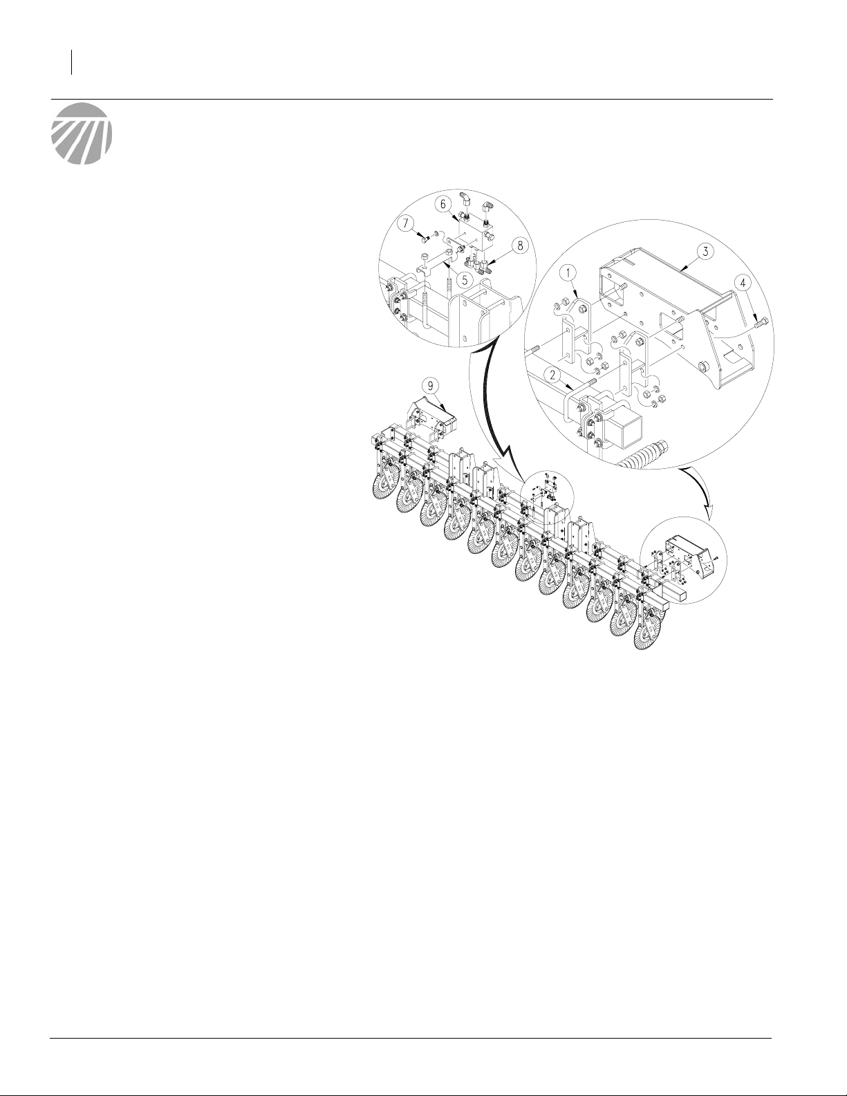
Refer to Figure 1
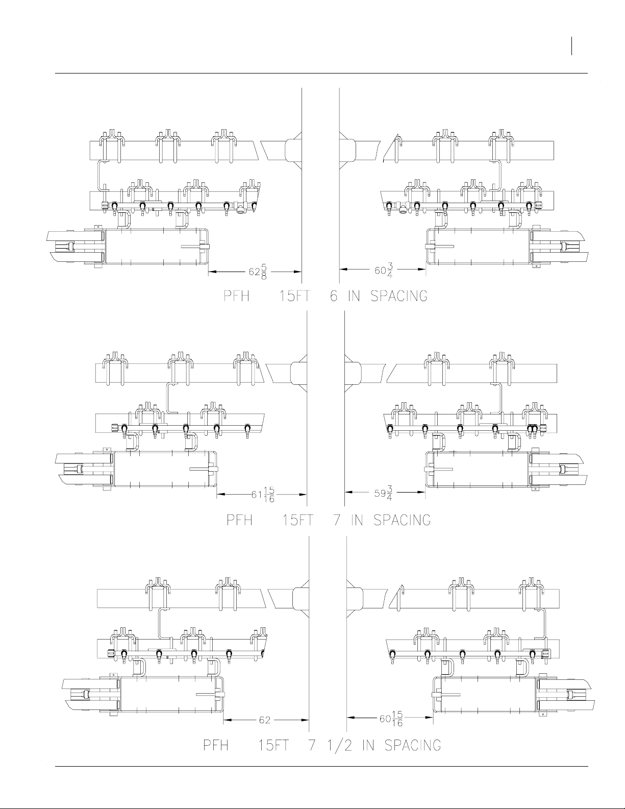
Note: Refer to charts on pages 7, 8, 9 or 10 for
measurements appropriate to your drill width and
row spacing.
1. Lower the hitch to field position. Allow clearance of 9’ on a 15’ drill and 11’ on a 20’ drill
fromeach end ofthecoulter tool barformarker
assembly.
2. On the left-hand side of the drill position the
two marker mount adapters (1) on the 4”
squaretube and holdin place with5/8”x 4” x6”
U-bolts (2), 5/8” lock washers and 5/8” nuts,
leaving nuts loose.
Note:On the20’ markerwith 6”and 71/2”spacings
(left side only) two 5/8” x 6 1/2” hex bolts are used
in place of the U-bolt. Remove the bolts used to
mount the tool bar and insert the 6 1/2” bolts.
3. Usingthe appropriate chart for holelocation attachthe marker mount (3) tothemarkermount
adapters (1) using 5/8” x 1 3/4” bolts 5/8” lock
washers and 5/8” nuts. Tighten bolts.
4. Measure from the inside end of the marker
mount(3)to the outside surface of thedrill center frame as shown in the charts.Set the markermount (3) tothecorrect distance andtighten
U-bolts (2).
5. Install the right-hand marker mount (9) to the
right-hand side using steps 2 through 4.
6. Install the marker valve mount (5) just to the
rightof centeron thecoulter frametube.Clamp
the marker valvemount (5) in place with a 1/2”
x 4” x 5 1/4” U-bolt. Assemble the valve (6) to
themount with the 4-port side downwardusing
two 3/8" x 3/4" long bolts (7) and 3/8” lock
washers.
7. Installthe six JCIfittings in the ports with the elbows facing out.
20186
Figure 1
Assembly
NOTE: JIC fittings do not require high torque. JIC
and O-Ring fittings do not require sealant. Always
use liquid pipe sealant when adding or replacing
pipe thread fittings. Toavoid possible danger of
crackinghydraulic fittings from overtightening, DO
NOT use plastic sealant tape.
4/9/2004
Page 9
Assembly
7
4/9/2004
20254
Page 10

Precision Fertilizer Hitch
8
20255
4/9/2004
Page 11

Assembly
9
20256
4/9/2004
Page 12

Precision Fertilizer Hitch
10
20253
4/9/2004
Page 13

Refer to Figure 2
8. Route the hoses from each marker through
the mount and out the opening in the inside
end of the mount.
9. Routethe hoses alongthe coulter frame tube
and tie them to the tube with the releasable
cable ties (6).
10. Connect the hoses to the sequence valve(7)
with four JIC elbows (5). Note the port markings and refer to the drawing for proper connections.
11. Connect the two 156" long hoses (8) to the
two top ports of the sequence valve with two
elbows (5) and route them to the tongue and
through the hose loop. Use releasable cable
ties to secure hose to frame.
Assembly
11
NOTE:Check the hydraulicfluid in the tractor reservoir and fill it to the proper level. Add fluid to the
system as needed. A low reservoir may draw air
back into the system causing jerky or uneven
movement. The fluid capacity of the markers is
.75 gallons.
12. With the first section in the lowered position,
connect the hoses to the tractor and cycle
each cylinder 3 or 4 times. Both arms should
moveto the vertical position on the first move
and then they should lower and raise alternately as the hydraulic lever is operated.
!
DANGER
Keep all persons clear of the marker when operating.
Air in the hydraulic system can cause the marker arm
to drop quickly. Make sure the system is properly
charged.
20187
Figure 2
Hydraulic Assembly
4/9/2004
Page 14

Precision Fertilizer Hitch
12
Refer to Figure 3
13. Check the orientation of the second section
mountingpin (1). Thesecond stage mounting
pin (1) mustbe assembledinto the hinge with
theflanged headtowardthe tongueend ofthe
hitch for the breakaway to work properly, If
not, pull it out and insert it from the other direction.
14. Remove the rear 1/2 x 3 1/2 long bolt (2) from
the second section mount and install the second marker section (3) between the plates.
Align the holes and replace the bolt and lock
nut. Bolt the front flange on the second section to the flange on the second section
mounting pin with a 5/16 x 1 1/2 long grade 5
bolt (4) and locknut (5).
Disk Adjustments
Refer to Figure 4
Disk Angle
1. To change the angle of cut, loosen the two
bolts (1),rotatethediskassemblyand retighten.
Marker Width
2. Marker width adjustments are made by loosening the marker tube U-bolt (2) and sliding it
in or out to the desired width and retightening
the U-bolt.
20188
12433
Figure 3
Second Section
Figure 4
Disk Adjustments
4/9/2004
Page 15

Hydraulic System
Adjusting The Hydraulics
1. Be sure tractor hydraulic reservoir is full.
2. Foldand unfold the marker(s) slowly in order
to work all the air out of your marker hydraulics. Use caution when folding and unfolding
the marker for the first time, and check for
pinching and kinking of hoses.
!
CAUTION
Never allow anyone near the drill when cycling the
markers.
3. Themarkerhydraulicsystem isequipped with
needlevalvesto controlhowfasteach marker
operates.The needle valves are built into the
sequence valve body. There are two hex adjustment heads, one for raising the markers,
and one for lowering the markers. These are
stamped in the valve body. To adjust the
speedof eachmarker,screw theneedle valve
clockwise to adjust the raise or lower marker
speedto alowsetting.Foldthe markerup and
down a few times and recheck for pinching
and kinking of hoses. With the tractor engine
at an operating rpm, adjust the needle valve
to limit the marker to a safe operating speed.
Excessive folding speeds can cause marker
damage.
Hydraulic System
13
!
CAUTION
Escaping Fluid under pressure can have sufficient
force to penetrate the skin. Check all hydraulic lines
and hoses before applying pressure. Fluid escaping
froma very small hole can be almost invisible.Use paper or cardboard,not body parts, to check for suspected leaks. If injured, seek medical assistance form a
doctor who is familiar with this type of injury. Foreign
fluids in the tissue must be surgically removedwithin a
few hours or gangrene will result.
General Notes
The markers cycle in the following sequence:
(1) Right Up, Left Up
(2) Right Down, Left Up
(3) Right Up, Left Up
(4) Right Up, Left Down
(5) Sequence Repeats
4/9/2004
NOTE:JIC fittings do not require high torque.JIC and O-Ring
fittings do not require sealant. Always use liquid pipe sealant
when adding or replacing pipe thread fittings. To avoid possible danger of cracking hydraulic fittings from over tightening,
DO NOT use plastic sealant tape.
Page 16

Precision Fertilizer Hitch
14
Maintenance and Lubrication
Maintenance
Proper servicing and adjustment is the key to the long
life of any farm implement. With careful and systematic
inspection, you can avoid costly maintenance, downtime and repair.
Breakaway Protection
The marker arm is attached to the marker body with a
5/16" breakaway bolt. If excessive force is put on the
markerduringoperation,the bolt will break, allowing the
marker arm to swing away rather than cause damage to
the marker.
NOTE: The breakaway bolt is a 5/16"-18 x 1 1/2" long
grade5 (G.P.# 802-012C). It isidentified as a grade5 by
having three marks on the head. If it breaks, it must be
replacedby an equivalentgrade5bolt to preventmarker
damage.
Lubrication
Marker Transporting
Always transport the marker with it folded in the flat fold
position.
Storage
Clean the PFH Flat Fold Marker as necessary.
1. Lubricate zerks as indicated in the lubrication section.
2. Storethe PFH Flat FoldMarker inside,if possible, for
longer PFH Flat Fold Marker life.
10
20189
20190
12436
Zerks
Type of Lubrication: Grease after 10 hours of use.
10
Zerks
Type of Lubrication: Grease after 10 hours of use.
Seasonally
Disk Bearings
Type of Lubrication: Grease at the beginning of each
season.
4/9/2004
Page 17

Troubleshooting
Problem Solution
Troubleshooting
15
Hydraulic marker functioning
improperly
Blade does not mark
Check all hose fittings and connections for air and oil leaks.
Check tractor hydraulic oil level.
Check all bolts and fasteners.
If needle valve is plugged; open valve, cycle markers and reset the needle valve.
The maximum marker down float is limited by the slot in the pivot link. If the blade does
not drop down to follow depressions in the field, make sure the marker cylinder is fully
extended.
4/9/2004
Page 18

Precision Fertilizer Hitch
16
Parts
Flat Fold Marker Assembly
20191
4/9/2004
Page 19

Ref. Part No. Description
1. 804-017C WASHER FLAT 1/2 USS PLT
2. 802-041C HHCS 1/2-13X3 1/2 GR5
3. 113-563S MARKER DISC & HUB ASSEMBLY
4. 803-019C NUT LOCK 1/2-13 PLT
5. 113-353D MARKER TUBE 51 LG
6. 113-449H 6 ROW 2ND STAGE ARM WMNT
113-450H 8 ROW 2ND STAGE ARM WMNT
7. 113-440H 2ND STAGE MOUNT WMNT
8. 803-011C NUT LOCK 5/16-18 PLT
9. 113-442H 2ND STAGE MOUNT PIN
10. 802-012C HHCS 5/16-18X1 1/2 GR5
11. 113-439D 1ST STAGE MOUNTING PIN
12. 810-196C CYL 2.5X10X1.12 ROD (TIE)
13. 113-766H MARKER MOUNT ADAPTOR
14. 805-180C PIN ROLL 1/4 X 1 1/2 LG PLT
15. 802-053C HHCS 5/8-11X1 3/4 GR5
16. 802-335C HHCS 5/8-11X6 1/2 GR5
17. 113-765H MARKER MOUNT PFH
18. 801-045C SCREW SET 1/4-28X1/4 KNL CUP
19. 817-145C THREAD PROTECTOR-DELRIN
20. 113-444H CYLINDER TANG WMNT
21. 890-143C BUSHING HARDENED 1 1/4-1-3/4 L
22. 113-438D CYLINDER LINK PIN
23. 113-437H 1ST STAGE ARM WELDMENT
24. 113-448H CYL. PIVOT PIN WMNT
25. 800-001C GREASE ZERK STRAIGHT 1/4-28
26. 805-060C PIN COTTER 7/32 X 2
27. 113-447E PIVOT LINK WELDMENT
28. 113-453S PIVOT LINK BUSHING ASSY
29. 113-446H TRANSFER LINK WMNT
30. 816-166C O-RING 1 ID X 1 1/4 OD X 1/8
31. 806-103C U-BOLT 1/2-13 1 17/32 X 2 3/4
32. 818-349C DECAL GREASE 10 HRS LH
33. 804-022C WASHER LOCK SPRING 5/8 PLT
34. 803-021C NUT HEX 5/8-11 PLT
35. 818-402C DECAL GREASE 10 HRS RH
36. 806-105C U-BOLT 5/8-11 X 4 1/32 X 6
37. 802-262C HHCS 5/8-11X7 GR5
38. 838-265C DECAL REFLECTOR AMBER 1 1/2X9
39. 818-682C DECAL WARNING PINCH/CRUSH MRKR
Parts
17
4/9/2004
Page 20

Precision Fertilizer Hitch
18
Disk Assembly
12426
4/9/2004
Page 21

Ref. Part No. Description
1. 113-563S MARKER DISC & HUB ASSEMBLY
113-564S REP BY 113-563S
113-372S REP BY 113-564S
2. 113-562H 1 SPINDLE MARKER WELDMENT
3. 816-014C TINE GAUGE MARKER HUB SEAL
4. 822-030C BEARING CONE L44643
5. 822-080C BEARING CUP L44610
6. 890-614C GREASE CAP #1505
7. 815-001C TINE GW HUB
8. 804-025C WASHER FLAT 3/4 SAE PLT
9. 803-053C NUT HEX SLOTTED 3/4-16
10. 805-019C PIN COTTER 5/32 X 1 PLT
11. 820-094C 16 4-BOLT NOTCHED MARKER DISK
12. 133-369H DEPTH BAND 10 4-BOLT 4B.C.
13. BO-47 NEILSON STUD 1/2-20UNF X 1 13/16
14. 803-159C NUT LUG 1/2-20 X 60 DEG PLT
Parts
19
4/9/2004
Page 22

Precision Fertilizer Hitch
20
Hydraulic Assembly
20192
4/9/2004
Page 23

Ref. Part No. Description
1. 810-196C CYL 2.5X10X1.12 ROD (TIE)
2. 811-065C EL 9/16MJIC 9/16MORB
3. 811-226C HH1/4R1 127 9/16FJIC Used on 20’
811-230C HH1/4R1 095 9/16FJIC Used on 15’
4. 811-436C HH1/4R1 156 9/16FJIC 1/2MNPT
5. 806-056C U-BOLT 1/2-13 X 4 1/32 X 5 1/4
6. 803-019C NUT LOCK 1/2-13 PLT
7. 149-562D SEQ VALVE MOUNT 4IN TUBE
8. 811-169C EL 9/16MJIC 9/16FJIC
9. 800-035C CABLE TIE .31X28 8DIA 120LB
10. 811-178C HH1/4R1 114 9/16FJIC Used on 20’
811-211C HH1/4R1 084 9/16FJIC Used on 15’
11. 810-197C VALVE,SEQUENCE SHOEMAKER
12. 802-014C HHCS 3/8-16X3/4 GR5
13. 804-013C WASHER LOCK SPRING 3/8 PLT
Parts
21
4/9/2004
Page 24

Precision Fertilizer Hitch
22
Hydraulic Cylinder (810-196C)
12027
4/9/2004
Page 25

Ref. Part No. Description
1. 2A0022 PISTON NUT
2. 4M3102 PISTON
3. * BACK-UP
4. * O-RING
5. 3R0310 MW HEAD
6. 2A0012 TIE ROD NUT
7. * O-RING
8. * BACK-UP
9. * WIPER SEAL
10. 2M3393 MW ROD
11. 5M3118 TUBE
12. 7M3318 TIE ROD
13. 6R0154 BASE MIDWAY
14. 2A0126 HEX PORT PLUG
15. 810-210C SEAL KIT
*CAN ONLY BE ORDERED IN SEAL KIT (15)
Parts
23
4/9/2004
Page 26

Precision Fertilizer Hitch
24
Sequence Valve (810-197C)
12024
4/9/2004
Page 27

Ref. Part No. Description
1. 3089 BODY, SEQUENCE VALVE
2. 1088-908 O-RING
3. 1132-08 PLUG, HEX SOCKET
4. 1179 NEEDLE, FLOW CONTROL
5. 1217 PIN .125" SPRING PIN
6. 1211 SPRING, COMPRESSION
7. 1088-011 O-RING
8. 1089-011 RING, TEFLON BACK-UP
9. 1180 SCREW, FLOW CONTROL ADJUSTMENT
10. 1218 HEX, JAM NUT ZINC PLATED
11. 1099 SPRING, DETENT
12. 1087-250 CHROMIUM STEEL BALLS
13. 1087-437 CHROMIUM STEEL BALL
14. 1042 SPRING
15. 1088-906 O-RING
16. 1182 FITTING, PORT ADAPTOR
17. 1132-05 HEX, SOCKET O-RING PLUG
18. 1088-905 O-RING
19. 1092-6 CONNECTOR, STRAIGHT
20. 2153 SPOOL, MARKER SEQUENCE .055" ORIFICES
Parts
25
4/9/2004
Page 28

Precision Fertilizer Hitch
26
Appendix
Torque V alues Chart
Bolt Head Identification
Bolt Head Identification
Bolt Size
(Inches)
1
in-tpi
1/4" - 20 7.4 5.6 11 8 16 12 M 5 X 0.8 4 3 6 5 9 7
1/4" - 28 8.5 6 13 10 18 14 M 6 X 1 7 5 11 8 15 11
5/16 - 18 15 11 24 17 33 25 M 8 X 1.25 17 12 26 19 36 27
5/16" - 24 17 13 26 19 37 27 M 8 X 1 18 13 28 21 39 29
3/8" - 16 27 20 42 31 59 44 M10 X 1.5 33 24 52 39 72 53
3/8" - 24 31 22 47 35 67 49 M10 X 0.75 39 29 61 45 85 62
7/16" - 14 43 32 67 49 95 70 M12 X 1.75 58 42 91 67 125 93
7/16" - 20 49 36 75 55 105 78 M12 X 1.5 60 44 95 70 130 97
1/2" - 13 66 49 105 76 145 105 M12 X 1 90 66 105 77 145 105
1/2" - 20 75 55 115 85 165 120 M14 X 2 92 68 145 105 200 150
9/16" - 12 95 70 150 110 210 155 M14 X 1.5 99 73 155 115 215 160
9/16" - 18 105 79 165 120 235 170 M16 X 2 145 105 225 165 315 230
5/8" - 11 130 97 205 150 285 210 M16 X 1.5 155 115 240 180 335 245
5/8" - 18 150 110 230 170 325 240 M18 X 2.5 195 145 310 230 405 300
3/4" - 10 235 170 360 265 510 375 M18 X 1.5 220 165 350 260 485 355
3/4" - 16 260 190 405 295 570 420 M20 X 2.5 280 205 440 325 610 450
7/8" - 9 225 165 585 430 820 605 M20 X 1.5 310 230 650 480 900 665
7/8" - 14 250 185 640 475 905 670 M24 X 3 480 355 760 560 1050 780
1" - 8 340 250 875 645 1230 910 M24 X 2 525 390 830 610 1150 845
1" - 12 370 275 955 705 1350 995 M30 X 3.5 960 705 1510 1120 2100 1550
1-1/8" - 7 480 355 1080 795 1750 1290 M30 X 2 1060 785 1680 1240 2320 1710
1 1/8" - 12 540 395 1210 890 1960 1440 M36 X 3.5 1730 1270 2650 1950 3660 2700
1 1/4" - 7 680 500 1520 1120 2460 1820 M36 X 2 1880 1380 2960 2190 4100 3220
1 1/4" - 12 750 555 1680 1240 2730 2010
1 3/8" - 6 890 655 1990 1470 3230 2380
1 3/8" - 12 1010 745 2270 1670 3680 2710
1 1/2" - 6 1180 870 2640 1950 4290 3160
1 1/2" - 12 1330 980 2970 2190 4820 35604mm x pitch = nominal thread diameter in millimeters x thread pitch
Grade 2 Grade 5
N · m2ft-lb3N · m ft-lb N · m ft-lb mm x pitch4N · m ft-lb N · m ft-lb N · m ft-lb
Torque tolerance + 0%, -15% of torquing values. Unless otherwise specified use torque values listed above.
Grade 8
Bolt Size
(Metric)
1
in-tpi = nominal thread diameter in inches-threads per inch
5.8 8.8 10.9
Class 5.8 Class 8.8 Class 10.9
2
N· m = newton-meters
3
ft-lb= foot pounds
4/9/2004
Page 29

Warranty
Great Plains Manufacturing, Incorporated warrants to the original purchaser that this seeding equipment will be free from defects in material
and workmanship for a period of one year from the date of original purchasewhenusedas intended and under normal service and conditions
for personal use; 90 days for commercial or rental purposes. This Warranty is limited to the replacement of any defective part by Great Plains
Manufacturing, Incorporated and the installation by the dealer of any
such replacement part. Great Plains reserves the right to inspect any
equipment or part which are claimed to have been defective in material
or workmanship.
This Warranty does not apply to any part or product which in Great
Plains’ judgement shall have been misused or damaged by accident or
lack of normal maintenance or care, or which has been repaired or altered in a way which adversely affects its performance or reliability, or
which has been used for a purpose for which the product is not designed. This Warranty shall not apply if the product is towed at a speed
in excess of 20 miles per hour.
Claims under this Warranty must be made tothe dealerwhichoriginally
sold the product and all warranty adjustments must by made through
such dealer. Great Plains reserves the right to make changes in materials or design of the product at any time without notice.
This Warranty shall not be interpreted to render Great Plains liable for
damages of any kind, direct, consequential, or contingent, to property.
Furthermore,Great Plains shallnotbe liable fordamagesresulting from
any cause beyond its reasonable control. This Warranty does not extend to loss of crops, losses caused by harvest delays or any expense
or loss for labor, supplies, rental machinery or for any other reason.
No other warranty of any kind whatsoever, express or implied, is
made with respect to this sale; and all implied warranties of merchantability and fitness for a particular purpose which exceed
the obligations set forth in this written warranty are hereby disclaimed and excluded from this sale.
This Warranty is not valid unless registered with Great Plains Manufacturing, Incorporated within 10 days from the date of original purchase.
Appendix
27
4/9/2004
Page 30

Great Plains Manufacturing, Inc.
Corporate Office: P.O.Box 5060
Salina, Kansas 67402-5060 USA
 Loading...