

Page 1
Operator’s Manual
PFC1600 and PFC2000
Planter Fertilizer Carts
Manufacturing, Inc.
www.greatplainsmfg.com
Read the operator’s manual entirely. When you see this symbol, the subsequent
instructions and warnings are serious - follow without exception. Your life and
!
the lives of others depend on it!
26015
Cover illustration may show optional equipment not supplied with standard unit.
© Copyright 2007 Printed 03/28/2007 407-158M
Page 2

Table of Contents
Important Safety Information.................................... 1
Safety Decals........................................................... 6
Introduction................................................................9
Document Family................................................. 9
Description of Unit.................................................... 9
Intended Usage.................................................... 9
Using This Manual................................................... 9
Definitions............................................................ 9
Owner Assistance.................................................. 10
Preparation and Setup ............................................ 11
Pre-Setup Checklist............................................... 11
Planter Preparation................................................ 11
Hitching Cart to Planter.......................................... 12
Plan The Hitch ................................................... 12
If using Bulk Boxes......................................... 12
If Using Bulk Hoppers .................................... 12
Hitching With Empty Tank.................................. 13
Hitching With Loaded Tank................................13
Electrical and Monitor Connections ................... 14
Monitor Setup................................................. 14
Making Electrical Connections....................... 14
Make Fertilizer Connections .................................. 15
Cart Connection Overview................................. 15
Planter Connection Overview ............................ 15
Making Fertilizer Connections............................ 16
Bleeding Gauge Line ............................................. 17
Operating Instructions............................................ 18
Pre-Start Checklist................................................. 18
Tank Inspection...................................................... 18
Transporting the Cart............................................. 19
Loading Fertilizer ................................................... 20
Loading 1600 Gallon Tank.................................21
Loading 400 Gallon Tank...................................22
Field Pumping........................................................ 23
PFC2000 Pumping From 1600 Only..................24
PFC2000 Point Row Pumping from 1600...... 24
PFC1600 Pumping............................................. 25
PFC1600 Point Row Pumping from 1600...... 25
Pumping From 400 only.....................................26
Pumping 400 (Only) With Planter Pumps ...... 26
Point Row Pumping with Planter Pumps........ 27
Pumping 400 With Cart Pump ....................... 27
Point Row Pumping from 400 via Cart........... 28
Pumping From Both Tanks................................ 29
Point Row Pumping From 1600
in Both Mode.................................................. 29
Point Row Pumping From 400
in Both Mode.................................................. 29
Field Set-Up Checklist........................................... 30
Field Operation...................................................... 30
Planting.............................................................. 31
Electric Clutch Operation................................... 31
Electric Clutch Lock-Up.................................. 32
Parking and Storage.............................................. 33
Stopping/Standing ............................................. 33
Short-Term Parking ........................................... 33
Extended Parking .............................................. 34
Drain Bulk Material......................................... 34
Drain Lines..................................................... 34
Seasonal Storage.................................................. 36
Adjustments............................................................. 37
Pump Setting Determination.................................. 37
Liquid Fertilizer Strainers....................................... 38
Pump Strainer.................................................... 38
Quick-Fill Strainer.............................................. 38
Troubleshooting ...................................................... 39
General Troubleshooting....................................... 39
Maintenance and Lubrication................................. 41
Maintenance.......................................................... 41
Fertilizer Plumbing Maintenance ........................... 42
Tank Cleaning.................................................... 42
Strainer Maintenance......................................... 42
Lubrication............................................................. 43
Appendix.................................................................. 46
Specifications and Capacities................................ 46
Tire Inflation Chart................................................. 46
Torque Values Chart.............................................. 47
PFC2000 Plumbing................................................ 48
PFC1600 Plumbing................................................ 49
Planter Assembly Installation................................. 50
Warranty................................................................ 54
© Copyright 2007 All rights Reserved
Great PlainsManufacturing, Inc.pro videsthis publication “as is” without warranty of any kind, either expressed or implied. While every precaution has been taken in the preparation of this manual, Great Plains Manufacturing, Inc. assumes no responsibility for errors or omissions. Neither is any liability assumed for damages resulting from the use of
the information contained herein. Great Plains Manufacturing, Inc. reserves the right to revise and improve its products as it sees fit. This publication describes the state of this
product at the time of its publication, and may not reflect the product in the future.
The following are trademarks of Great Plains Mfg., Inc.: Application Systems, Ausherman, Land Pride, Great Plains
All other brands and product names are trademarks or registered trademarks of their respective holders.
03/28/2007 401-406M
Great Plains Manufacturing, Incorporated Tr ademarks
Printed in the United States of America.
Page 3
Important Safety Information
Look for Safety Symbol
The SAFETY ALERT SYMBOL indicates there is a
potential hazard to personal safety involved and extra
safety precaution must be taken. When you see this
symbol, be alert and carefully read the message that
follows it. In addition to design and configuration of
equipment, hazard control and accident preventionare
dependent upon the awareness, concern, prudence
and proper training of personnel involved in the operation, transport, maintenance and storage of equipment.
Be Aware of Signal Words
Signal words designate a degree or level of hazard
seriousness.
DANGER indicates an imminently hazardous situation
which, if not avoided, will result in death or serious
injury. This signal word is limited to the most extreme
situations, typically for machine components that, for
functional purposes, cannot be guarded.
WARNING indicates a potentially hazardous situation
which, if not avoided, could result in death or serious
injury, and includes hazards that are exposed when
guards are removed. It may also be used to alert
against unsafe practices.
CAUTION indicates a potentially hazardous situation
which, if not avoided, may result in minor or moderate
injury. It may also be used to alert against unsafe practices.
!
DANGER
!
WARNING
!
CAUTION
!
1
Be Familiar with Safety Decals
▲ Read and understand “Safety Decals” on page 6, thor-
oughly.
▲ Read all instructions noted on the decals.
▲ Keep decals clean. Replace damaged, faded and illegible
decals.
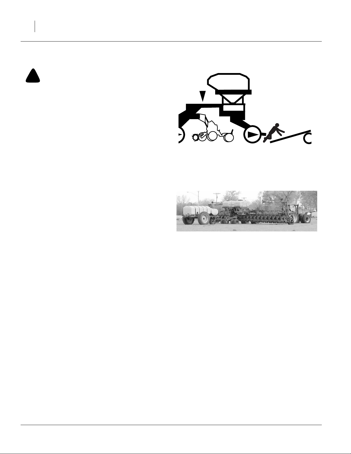
Keep Riders Off Machinery
Riders obstruct the operator’s view. Riders could be
struck by foreign objects or thrown from the machine.
▲ Never allow children to operate equipment.
▲ Keep all bystanders away from machine during opera-
tion.
03/28/2007 407-158M
Page 4

2
Handle Chemicals Properly
Agricultural chemicals can be dangerous. Improper
use can seriously injure persons, animals, plants, soil
and property.
▲ Read and follow chemical manufacturer’s instructions.
▲ Wear protective clothing.
▲ Handle all chemicals with care.
▲ Avoid inhaling smoke from any type of chemical fire.
▲ Never add chemical concentrates to an empty tank.
Start with tank half full of water.
▲ Rinse out tank tanks and discard rinse water on last field
treated.
▲ Never drain, rinse or wash tank or its plumbing within
100 feet of a freshwater source, nor at a car wash.
▲ Store or dispose of unused chemicals as specified by
chemical manufacturer.
▲ Dispose of empty chemical containers properly. Laws
generally require power rinsing or rinsing three times,
followed by perforation of the container to prevent reuse.
Wear Protective Equipment
▲ Wear protective clothing and equipment specified by
chemical manufacturer.
▲ Wear clothing and equipment appropriate for the job.
Avoid loose-fitting clothing.
▲ Routine tank valve operation requires operator presence
under the cart. Wear a chemical-resistant hard hat.
▲ Because prolonged exposure to loud noise can cause
hearing impairment or hearing loss, wear suitable hearing protection such as earmuffs or earplugs.
▲ Because operating equipment safely requires your full
attention, avoid wearing entertainment headphones while
operating machinery.
▲ Make sure your respiration cartridges are suitable for the
chemicals, and not expired or clogged.
▲ Waterproof unlined gloves are essential for any workers
handling tank cart controls or hoses. Neoprene is recommended.
▲ Chemical jackets, gowns or aprons are essential for
workers loading chemicals or working beneath the cart.
▲ All workers need waterproof boots or foot coverings, to
avoid contact with both spilled and applied chemicals.
407-158M 03/28/2007
Page 5
3
Shutdown and Storage
▲ Drain and safely store or dispose of residual liquids.
▲ Flush tank(s) and lines with water. Winterize if freezing
weather is possible before next use.
▲ Secure cart using blocks at wheels.
▲ Detach and store cart in an area where children normally
do not play.
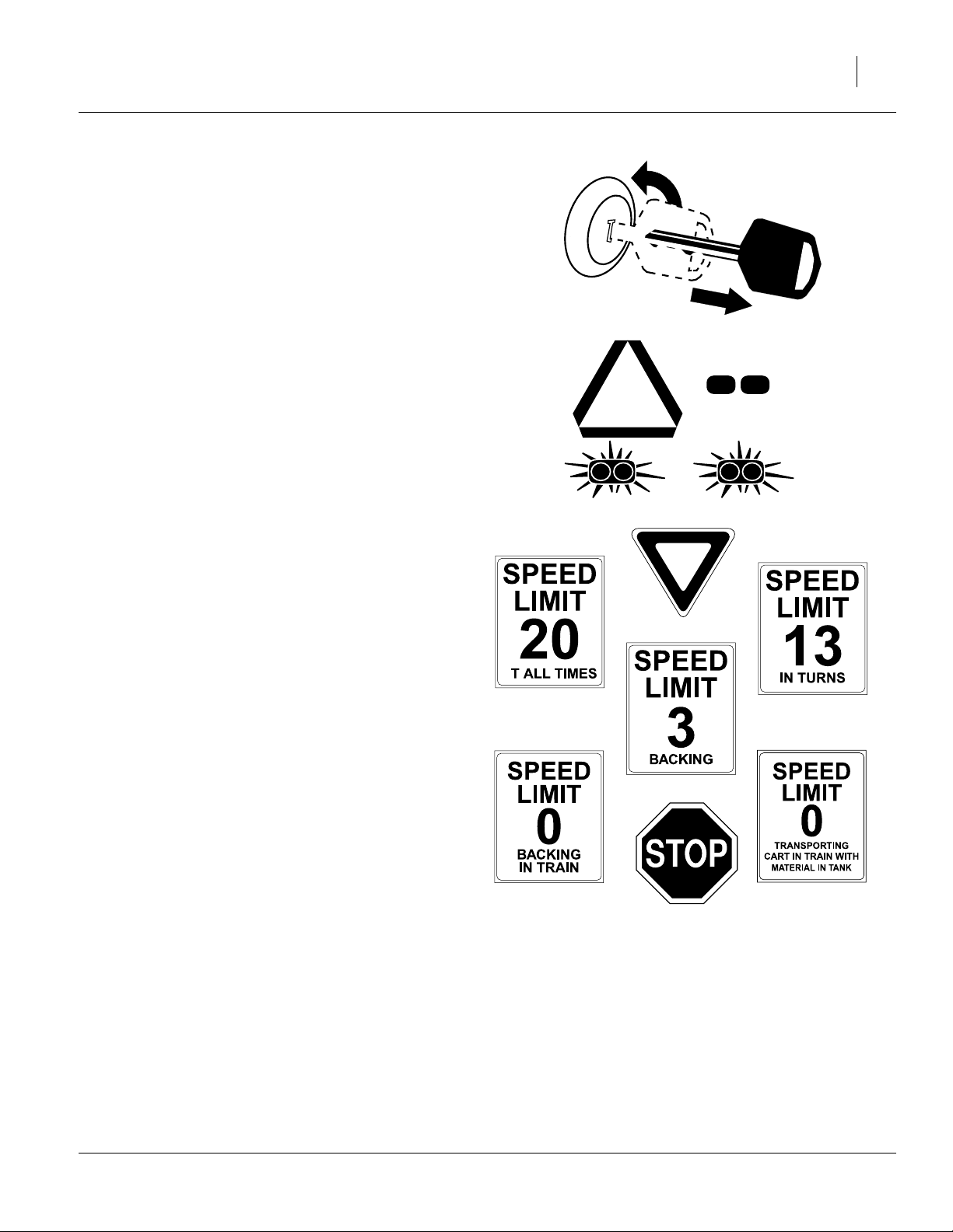
Use Safety Lights and Devices
Slow-moving tractors and towed implements can create a hazard when driven on public roads. They are
difficult to see, especially at night.
▲ Use flashing warning lights and turn signals whenever
driving on public roads.
Use lights and devices provided with implement
Transport Machinery Safely
Maximum transport speed for implement is 20 mph, 13
mph in turns. Some rough terrains require a slower
speed. Sudden braking can cause a towed load to
swerve and upset.
▲ Use the safety chain provided with the cart.
OFF
▲ Never transport the cart in train with the planter unless
the tanks are completely empty.
▲ Do not exceed 20 mph. Never travel at a speed which
does not allow adequate control of steering and stopping.
Reduce speed if towed load is not equipped with brakes.
▲ Do not attempt to back up with cart attached to planter.
Castering of the planter’s rear wheels, and the cart’s lead
wheel, make precise directional control difficult.
▲ Comply with state and local laws.
▲ Do not tow an implement train that, when fully loaded,
weighs more than 1.5 times the weight of towing vehicle.
▲ Carry reflectors or flags to mark cart in case of break-
down on the road.
▲ Keep clear of overhead power lines and other obstruc-
tions when transporting. Refer to transport dimensions
under “Specifications and Capacities” on page 46.
A
03/28/2007 407-158M
Page 6
4
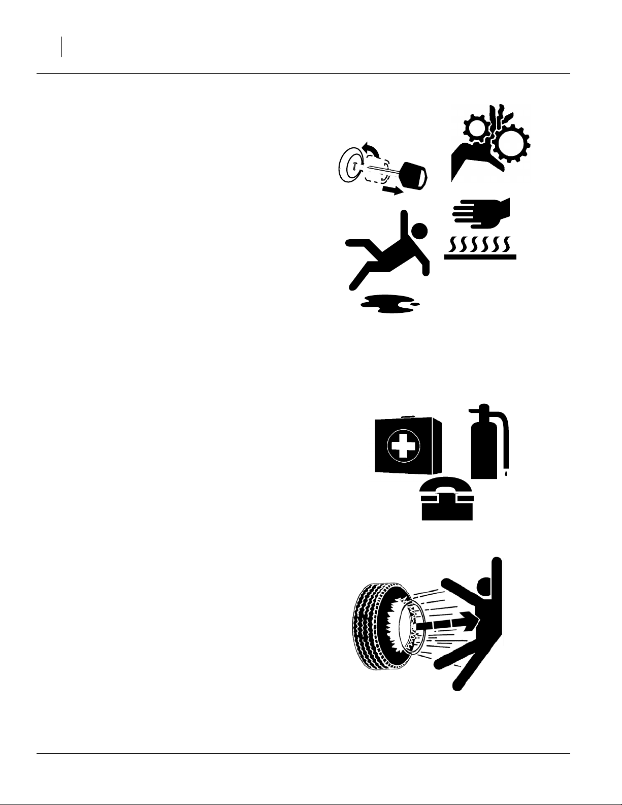
Practice Safe Maintenance
▲ Understand procedure before doing work. Use proper
tools and equipment. Refer to this manual for additional
information.
▲ Work in a clean, dry area.
▲ Put tractor in park, turn off engine, and remove key
before performing maintenance.
▲ Make sure all moving parts have stopped and all system
pressure is relieved.
▲ Allow cart pump to cool completely.
▲ Disconnect battery ground cable (-) before servicing or
adjusting electrical systems or before welding on cart.
▲ Inspect all parts. Make sure parts are in good condition
and installed properly.
▲ Remove buildup of grease, oil or debris.
OFF
▲ Remove all tools and unused parts from cart before oper-
ation.
Prepare for Emergencies
▲ Be prepared if a fire starts
▲ Keep a first aid kit and fire extinguisher handy.
▲ Keep emergency numbers for doctor,ambulance, hospital
and fire department near phone.
Tire Safety
Tire changing can be dangerous and should be performed by trained personnel using correct tools and
equipment.
▲ When inflating tires, use a clip-on chuck and extension
hose long enough for you to stand to one side–not in front
of or over tire assembly. Use a safety cage if available.
911
▲ When removing and installing wheels, use wheel-han-
dling equipment adequate for weight involved.
407-158M 03/28/2007
Page 7

Safety At All Times
Thoroughly read and understand the instructions in
this manual before operation. Read all instructions
noted on the safety decals.
▲ Be familiar with all cart functions.
▲ Operate machinery from the driver’s seat only.
▲ Do not leave cart unattended with tractor engine run-
ning.
▲ Do not dismount a moving tractor. Dismounting a mov-
ing tractor could cause serious injury or death.
▲ Do not stand between the tractor and cart or planter and
cart during hitching.
▲ Keep hands, feet and clothing away from power-driven
parts.
▲ Wear snug-fitting clothing to avoid entanglement with
moving parts.
5
▲ Watch out for wires, trees, etc., when folding and raising
cart. Make sure all persons are clear of working area.
03/28/2007 407-158M
Page 8
6
Safety Decals
Safety Reflectors and Decals
Your implement comes equipped with all lights, safety
reflectors and decals in place. They were designed to
help you safely operate your implement.
▲ Read and follow decal directions.
▲ Keep lights in operating condition.
▲ Keep all safety decals clean and legible.
▲ Replace all damaged or missing decals. Order new
decals from your Great Plains dealer. Refer to this section for proper decal placement.
▲ When ordering new parts or components, also request
corresponding safety decals.
To install new decals:
1. Clean the area on which the decal is to be placed.
2. Peel backing from decal. Press firmly on surface,
being careful not to cause air bubbles under decal.
818-055C
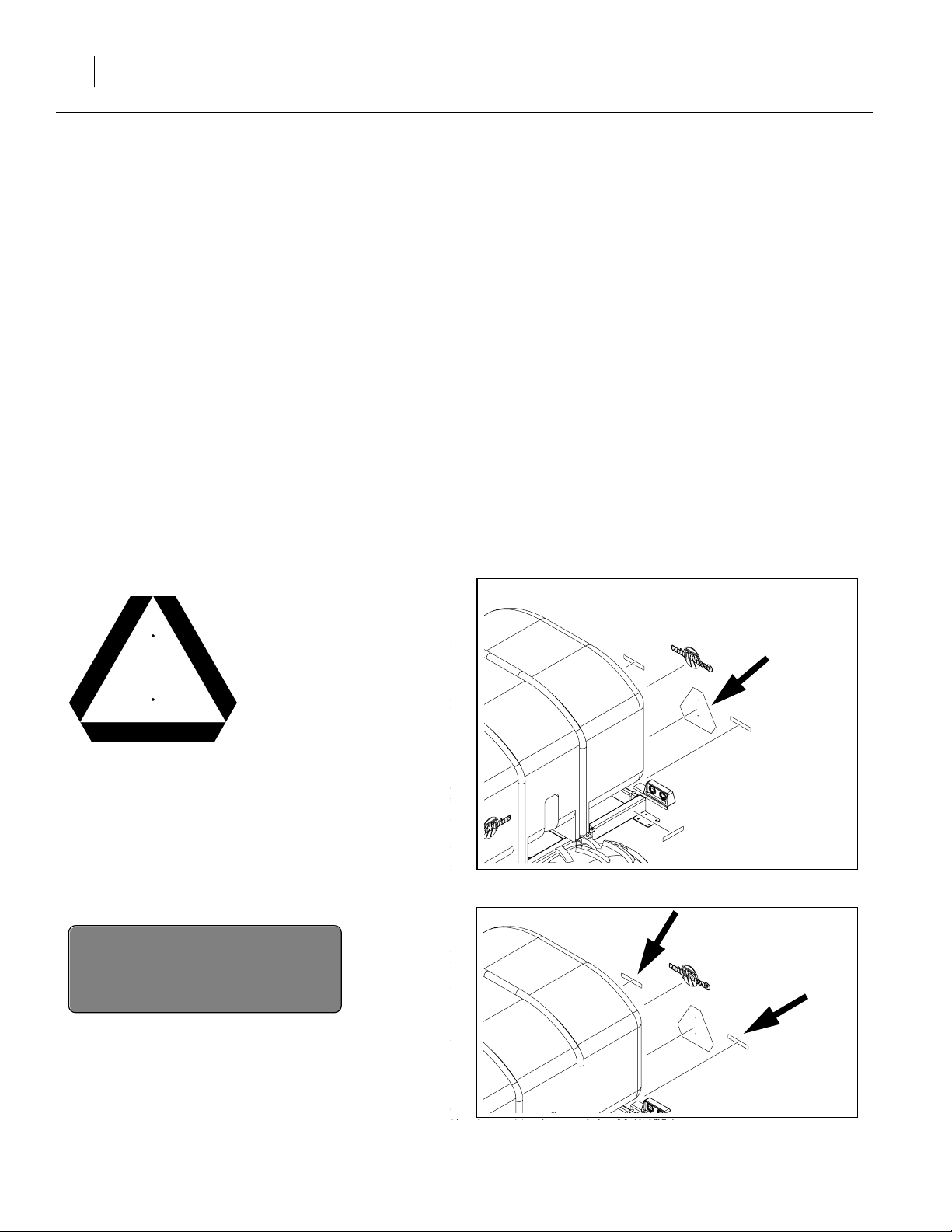
Slow Moving Vehicle Reflector
On the back of the cart, frame center;
1 total
838-266C
26016
Red Reflectors
On the main frame back, each side;
two total
26016
407-158M 03/28/2007
Page 9
838-255C
Amber Reflectors
On the main frame sides, front and back,
on the main frame front, each side;
six total.
7
26016
26016
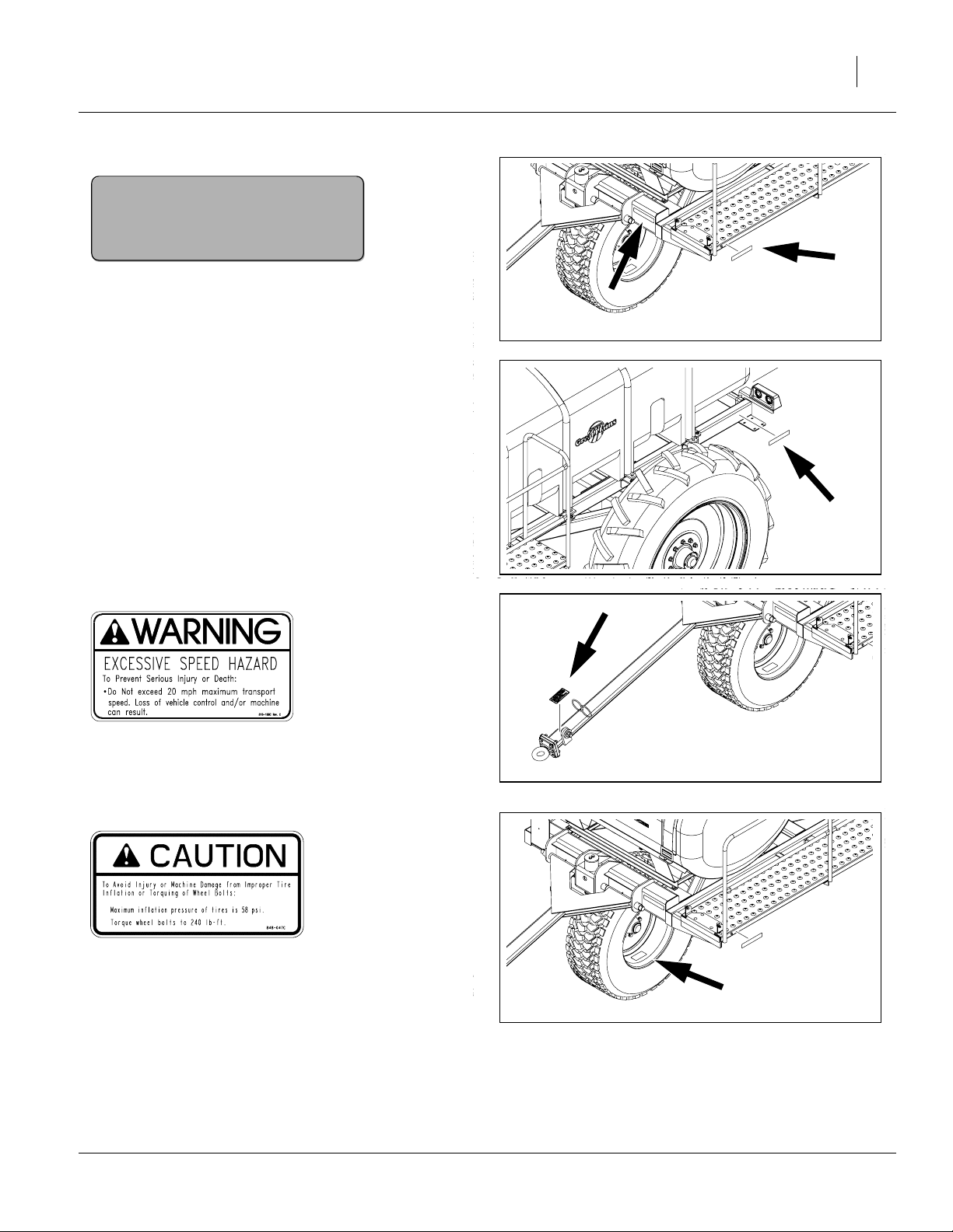
818-188C
Warning: Transport Speed
On tongue, one total
848-047C
Caution: Tire Pressure & Torque
Inside rim of front caster wheel;
one total
26016
26016
03/28/2007 407-158M
Page 10
8
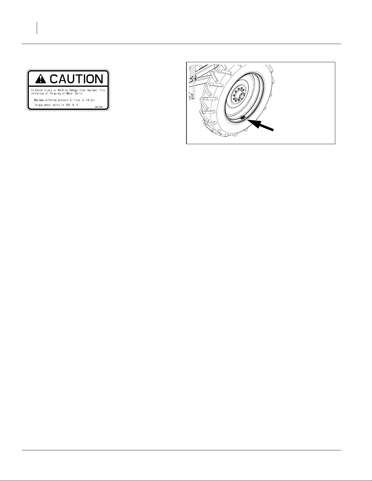
848-048C
Caution: Tire Pressure & Torque
Inside rim of main wheels;
two total
26016
407-158M 03/28/2007
Page 11

Introduction
Introduction 9
Great Plains welcomes you to its growing family of new
product owners. Your PFC1600 or PFC2000 Planter
Fertilizer Cart has been designed with care and built by
skilled workers using quality materials. Proper setup,
maintenance, and safe operating practices will help you
get years of satisfactory use from the machine.
Document Family
407-158M Owner’s Manual (this document)
407-158P Parts
(Note1) Pump Instruction/Parts Manual
(Note2) Planter Operator’s Manual
(Note1) DICKEY-john Seed Monitor Manual
1 Pump and seed monitor manuals supplied by their
respective manufacturers, and not separately orderable
from Great Plains.
2. There may be more than one Great Plains Planter that
supports these tank carts. The planter manual may
include important tank setup and operating information.
Description of Unit
The PFC1600/2000 Cart is a pull-type implement for
supplying liquid fertilizer to specific supporting models
of Great Plains planters. At time of publication, the following planter models accepted PFC1600/2000 Carts:
YP2425 60ft Yield-Pro Planter
Use with any planter requires:
• Trailing pintle hook hitch
• 3-inlet “Hi-Rate” fertilizer manifold
• On-planter fertilizerpump if single-inlet “Starter” manifold is also installed
If your planter does not havethese prerequisite systems
and features, it may be possible to add them. Consult
your Great Plains dealer.
Intended Usage
Use the PFC1600/2000 Cart to apply liquid fertilizer to
production-agriculture crops only.
Do not use the cart to store, transport or apply herbicides or insecticides, nor to store or transport water for
potable uses.
Do not modify the cart for use with planters or attachments other than Great Plains products specified for
use with the PFC1600/2000 Cart.
Using This Manual
This manual will familiarize you with safety, assembly,
operation, adjustments, troubleshooting, and maintenance. Read this manual and follow the recommendations to help ensure safe and efficient operation.
The information in this manual is current at printing.
Some parts may change to assure top performance.
Definitions
The following terms are used throughout this manual.
Right-hand and left-hand as used in this manual are
determined by facing the direction the machine will
travel while in use unless otherwise stated.
IMPORTANT !
A crucial point of information related to the preceding
topic. Read and follow the directions to remain saf e,
avoid serious damage to equipment and ensure
desired field results.
Note: Useful information related to the preceding topic.
03/28/2007 407-158M
Page 12
10
Owner Assistance
If you need customer service or repair parts,contact a
Great Plains dealer. They have trained personnel,
repair parts and equipment specially designed for
Great Plains products.
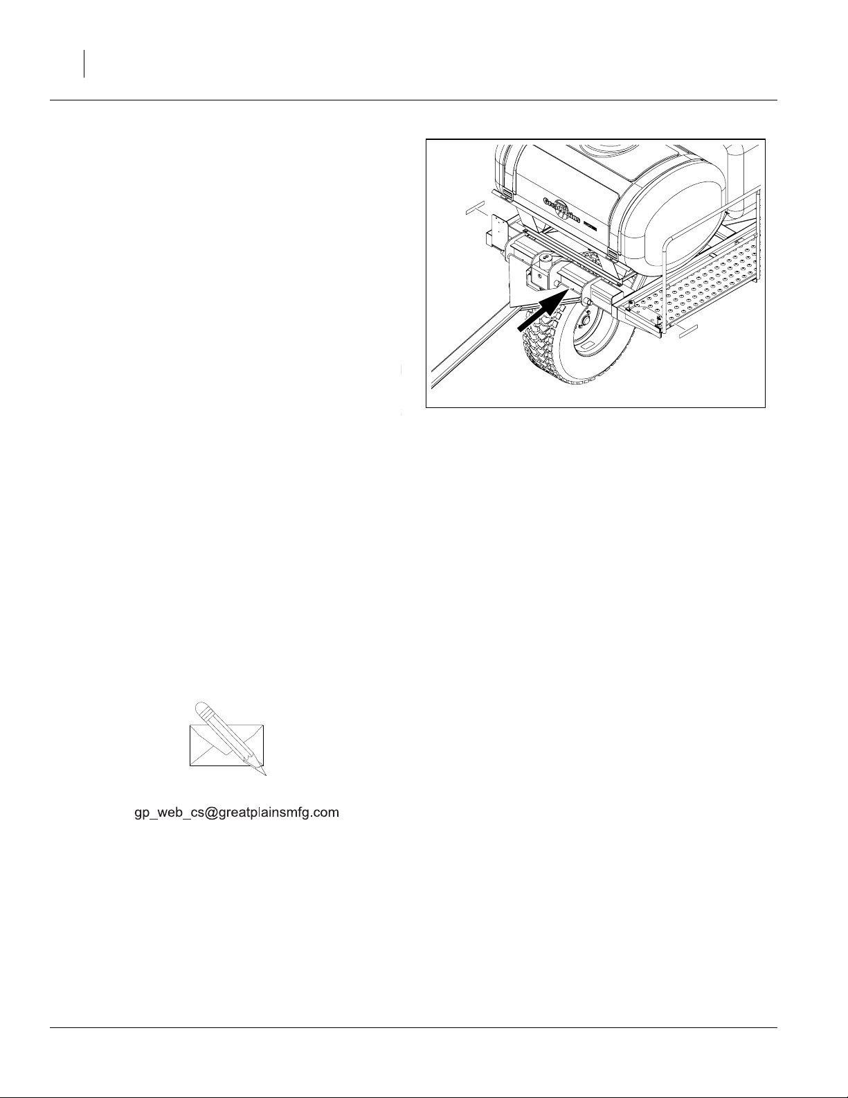
Refer to Figure 1
Your machine’s parts were specially designed and
should only be replaced with Great Plains parts.
Always use the serial and model number when ordering parts from your Great Plains dealer. The serialnumber plate is located on the left end of the seed cart
tool bar, as shown.
Record your PFC1600/2000 Cart model and serial
number here for quick reference:
Model Number:__________________________
Serial Number: __________________________
Your Great Plains dealer wants you to be satisfied with
your new machine. If you do not understand any part
of this manual or are not satisfied with the service
received, please take the following actions.
1. Discuss the matter with your dealership service
manager. Make sure they are aware of any problems so they can assist you.
Figure 1
Serial Number Plate
26016
2. If you are still unsatisfied, seek out the owner or
general manager of the dealership.
For further assistance write to:
Product Support
Great Plains Mfg. Inc., Service Department
PO Box 5060
Salina, KS 67402-5060
785-823-3276
407-158M 03/28/2007
Page 13

Preparation and Setup
This section helps you prepare your tractor and
PFC1600/2000 Cart for use, and covers tasks that
need to be done only once per hitch, seasonally, or
when the tractor/cart configuration changes.
Before using the PFC1600/2000 Cart in the field, you
must hitch the cartto a compatible planter.Periodically
thereafter, maintenance is required.
Pre-Setup Checklist
1. Read and understand “Important Safety Information” on page 1.
2. Check that all working parts are moving freely,
bolts are tight, and cotter pins are spread.
3. Check that all grease fittings are in place and lubricated. See “Lubrication” on page 43.
4. Check that all safety decals and reflectors are correctly located and legible. Replace if damaged.
See “Safety Decals” on page 6.
5. Inflate tires to pressure recommended and tighten
wheel bolts as specified. See “Tire Inflation
Chart” on page 46.
Preparation and Setup 11
Planter Preparation
The PFC1600/2000 Cartsare designed to be towed, in
train, behind the Great Plains YP2425 planter. The
planter must be ordered with, or upgraded to include:
• rear pintle hitch ( in Figure 2), and
• the “Hi-Rate” fertilizer manifold, which includes 3
inlet ports at the back of the planter ( in Figure 2)
and if the PFC2000 tank, intended for dual materials:
• “Starter” manifold system (single inlet), and
• ground drive fertilizer pumps
If the PFC1600/2000 Cart was purchased on the same
order with the YP2425, two cart-supporting cable
assemblies ( in Figure 2) and one pressure gauge
3
line ( in Figure 2) will have been installed on the
planter at the factory. These assemblies extend the
lighting and CANbus circuits to the rear pintle hitch on
the planter, and extend pressure status to the planter.
If the PFC1600/2000 Cart was ordered separately,
these assemblies are supplied in a carton with the
cart, and must be installed on the planter prior to first
cart use. See “Planter Assembly Installation” on
page 50.
1
2
4
2
4
1
Figure 2
YP2425 Cart Hitch & Inlets
2
3
26035
03/28/2007 407-158M
Page 14
12
Hitching Cart to Planter
!
DANGER
Exercise extreme care in hitching.
▲ The rear wheels and rear hitch of the YP2425 planter
move during planter raise/lower operations.
▲ If planter movements are required, it will be difficult for
the tractor operator to see the tank cart hitch and anyone
near it.
▲ If the planter is moved, both tractor operator and hitch
observer must be within sight of each other for prearranged hand signals, or must be in continuous electronic communication.
▲ Hitch only on level ground. The tank cart has no brakes.
Plan The Hitch
There are some situations to avoid in preparing the
planter/tank for the field:
• Spot the planter so that only forward moves are
required after hitching the cart.Itis difficult to control
reverse steering of the train.
• When the cart is loaded with fertilizer, it generally
cannot be moved by hand safely. If extra power
equipment is not available, plan to hitch the tank
cart by hand-moving the cart when empty.
• When the cart is hitched to the planter, it prevents
fork-lift access to the back of the planter for loading
seed in bulk boxes. The planter can be side-loaded
(when folded), but only if the fork lift is rated for the
long reach required.
• If seed is pre-loaded before planter highway movement, steering and braking hazards increase (as
well as wear on wheel bearings). If fertilizer is also
loaded before highway movement, you will exceed
the control ability of any tractor.
Load fertilizer in the field. If this is not possible, tow the
pre-loaded cart to the field by itself, and not in train
with the planter.
Figure 3
Tank Cart in Train
26049
If using Bulk Boxes
1. Move empty planter and tank cart to field.
2. Load boxed seed on planter.
3. Hitch empty tank cart to planter.
4. Load fertilizer.
407-158M 03/28/2007
If Using Bulk Hoppers
1. Move empty planter and tank cart to field.
2. Install seed hoppers.
3. Load seed with auger.
4. Hitch empty tank cart to planter.
5. Load fertilizer.
Page 15

Hitching With Empty Tank
1. Position planter for forward-only movement after
hitching. Set parking brake on tractor and shut off
tractor. Planter may be raised or lowered.
2. Have two people move the cart to engage the
tongue loop with the pintle hitch.
3. Secure the safety chain around the rear hitch
weldment frame.
4. Remove wheel chocks.
Hitching With Loaded Tank
!
DANGER
Only do this for immediate field operations, and not transport. The planter plus a loaded tank cart is not safe to move
any distance on public roads, even if the tractor is rated for
80,000 pounds.
1. Raise and fold the planter, so that the hitch
observer does not need to stand beyond the
unfolded wing ends. Position planter for forwardonly movement after hitching.
Preparation and Setup 13
2. Picka spot for the hitch point, about six feet behind
the planter’s rear hitch. Place a small object at the
spot.
3. Using another towing implement pull the cart
toward the hitching point at an angle, from the
rear, and to the side of the planter. Stop when the
tongue loop is over the hitching point.
4. Disconnect the cart, lower the tongue loop to the
ground, and swing it back away from the planter.
5. Have the hitch observer stand clear of the planter
and signal to the tractor operator to back the
planter up slowly.
6. Signal stop when the pintle hitch is over the hitching spot.
7. Set the parking brake on the tractor and shut it off.
8. Engage the tongue loop with the pintle hitch.
9. Secure the safety chain around the hitch weldment
frame.
10. Remove wheel chocks.
03/28/2007 407-158M
Page 16

14
Electrical and Monitor Connections
Monitor Setup
Before using the cart for the first time, it is necessary
to configure the planter seed monitor to correctly process cart signals and correctly control the clutch and
manifold valves.
For the 3-inlet Hi-Rate” manifold, this configuration
includes telling the monitor which row number range is
served by each inlet. If your manifold system has one
drop line per row unit, Clutch Switch Coverage table in
the planter Operator’s Manual shows the row unit numbers for Left/Center/Right.
Making Electrical Connections
Refer to Figure 4
Make sure tractor is shut down with accessory power
off before making connections.
11. Mate the lighting plug to the outlet connector on
the planter.
1
25421
1
12. Mate the pump control cable to the DICKEY-
2
john outlet on the planter.
13. Secure cables so they do not get caught in pintle
hitch. Failure to do so could cause cables to be
crushed, requiring cable replacement, and possible electrical damage to systems.
Figure 4
Connector Identification
2
26144
25237
407-158M 03/28/2007
Page 17
Make Fertilizer Connections
!
CAUTION
Always wear chemical gloves and other protective apparel
and equipment specified for the materials to be applied.
Material hose connections depend on your planter
configuration, cart model, and intended application.
Refer to Figure 5 and to Figure 23 and Figure24 on pages
48 and 49.
Cart Connection Overview
1. Manifold port 1, 2in CAM
This hose supplies the “Hi-Rate” manifold section
on the left side of the planter.
2. Manifold port 2, 2in CAM
This hose supplies the “Hi-Rate” manifold section
in the center section of the planter.
3. Manifold port 3, 2in CAM
This hose supplies the “Hi-Rate” manifold section
on the right side of the planter.
4. Manifold port 4, no hose
By-pass to 1600 gallon tank. Opened by seed
monitor whenever any of ports 1, 2 or 3 are closed.
5. Gauge line,
Supplies pressure gauge on planter
6. 400 Gallon Tank line, 2in CAM
Present only on model PFC2000, supplies single
line to ground drive pumps of “Starter” system on
planter.
3
⁄
in CAM
4
Preparation and Setup 15
4
5
1
2
3
Figure 5
PFC2000 Hose Connections
6
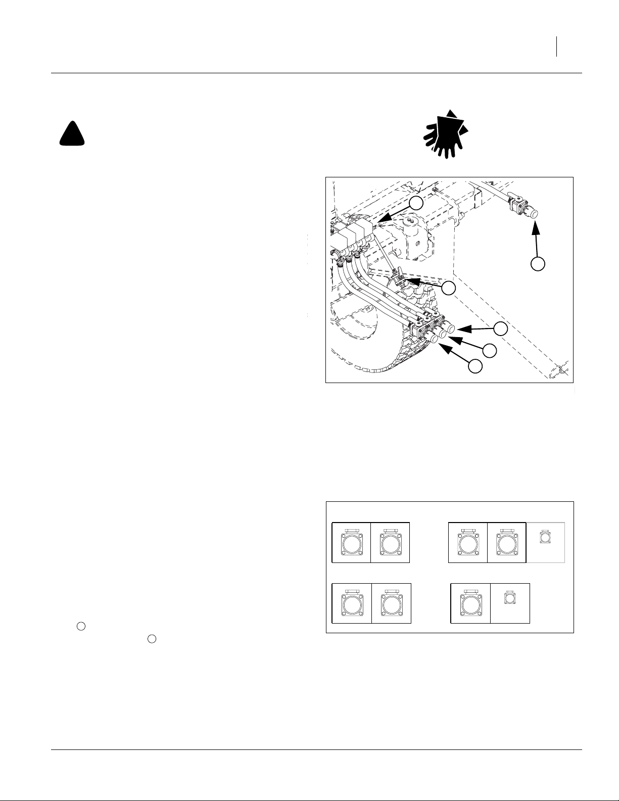
26145
Planter Connection Overview
L. Left Side, 2in CAM receptacle
Hi-rate inlet for planter left wing.
C. Center, 2in CAM receptacle
Hi-rate inlet for planter center section.
R. Right Side, 2in CAM receptacle
Hi-rate inlet for planter right wing.
S. Starter, 2in CAM receptacle
Inlet for entire starterfertilizer manifold. Present as
S
only if starter manifold installed; otherwise
gauge line inlet is mounted at this position.
G. Gauge Line,
Gauge (only) line for tank cartpump.Supplied with
tank cart. May be factory-installed. Tied to other
hoses if no bracket position available.
03/28/2007 407-158M
G
3
⁄
in CAM receptacle
4
Planter has both Starter & Hi-rate Systems
L
Planter has only Hi-rate System
L
C
C
YP2425 Fertilizer Inlets
R
R
Figure 6
S
G
G
26146
Page 18

16
Making Fertilizer Connections
PFC2000 Cart, YP2425 Planter with Starter and Hi-rate Manifolds, & Ground Drive Pumps
Cart Hose
Planter Inlet
1
L
2
C
3
R
5
G
PFC1600 Cart, YP2425 Planter with Hi-rate Manifold only
Cart Hose N/A
Planter Inlet
1
L
2
C
3
R
5
G
26147
26146
1. Wear chemical gloves and protective apparel.
2. Close all shut-off valves on hoses and inlets.
3. Clean any debris from outlets and inlets.
4. Make hose connections as shown in the table
above.
5. Secure any unused hoses as shown in Figure 7.
Fold them back and secure them to the cart
tongue so that the outlet valves point slightly
downward(topreventcollecting the dust thrown up
during normal planter operation).
6. Do not re-open connection valves until ready to
plant, and cart’s pump selector valve has been set
to desired tank.
6
S
Figure 7
26148
Secure Extra Hoses
407-158M 03/28/2007
Page 19

Bleeding Gauge Line
Refer to Figure 8
When operating the tank for the first time air must be
bled from the hose of “Hi-Rate” fertilizer gauge line .
Releasing air from this line makes the gauge reading
more reliable.
1. Open the bleed valve at the magnetic gauge on
the planter wing.
2. Plant and fertilizeuntil fluid is observed exiting the
dump line .
3. Stop planting, close the bleed valve, and resume
planting.
3
2
1
Preparation and Setup 17
2
1
3
Figure 8
Gauge Bleed Valve
26149
03/28/2007 407-158M
Page 20

18
Operating Instructions
This section covers general operating procedures.
Experience, machine familiarity, and the following
information will lead to efficient operation and good
working habits. Always operate farm machinery with
safety in mind.
Pre-Start Checklist
Perform the following steps before transporting the
PFC1600/2000 Cart to the field.
❑ Carefully read “Important Safety Information”on
page 1.
❑ Review the application instructions and Material
Safety Data Sheet (MSDS) for the fertilizer(s).
❑ Review the plumbing location/control diagram for
your tank cart.
❑ Lubricate cartas indicated under “Lubrication”on
page 43.
❑ Check all tires for proper inflation. See “Tire Infla-
tion Chart” on page 46.
❑ Check all bolts, pins, and fasteners. Torque as
shown in “Torque Values Chart” on page 47.
❑ Check cart for worn or damaged parts. Repair or
replace parts before going to the field.
❑ Check tank hoops and straps to be sure they are
tight and tanks are secure.
❑ Check fertilizer hoses, fittings, and valves for
leaks. Repair or replace before going to the field.
❑ Always inspect the tanks before use.
MSDS
Tank Inspection
1. Wear a respirator suitable for the material presently in or previously dispensed from the tank(s).
2. Swing the ladder down from its storage position on
the walkboard.
3. Remove the lid on each tank and inspect for:
- residual fertilizer incompatible with next use
- contaminants
- debris that might clog filters
- trapped animals lost tools, etc.
If it is necessary to flush a tank, or remove debris
too large to flush, see “Tank Cleaning” on
page 42.
4. Re-secure each lid and stow the ladder.
407-158M 03/28/2007
Inspection Access Ladder
Figure 9
26150
Page 21

Transporting the Cart
If heading to the field, before departing, ensure that
fertilizer rate has been determined, or that the necessary data is with you.
Empty, the cart adds 5,900 pounds. If towing in train
with the YP2425 planter, make sure that this does not
exceed the braking capability of the tractor.
If towing in train, plan the move so that no reverse
moves will be required. Direction in reverse cannot be
reliably controlled for distances more than a few feet.
!
DANGER
Never transport the cart, in train, if there is any liquid in the
tanks. Full, the cart weighs nearly 30,000 pounds and
makes the train uncontrollable on roads regardless of tractor capability.
1. Hitch.
Make both electrical and hose connections. See
“Hitching Cart to Planter” on page 12.
Operating Instructions 19
A
2. Set CFM “Fert.Pump” switch off.
3. Always have lights on for highway operation.
4. Comply with all federal, state and local safety laws
when traveling on public roads.
5. Travel with caution.
6. Keep train length in mind when clearing intersections. The YP2425 plus PFC1600/2000 Cart add
nearly 75 feet to the length of your tractor.
!
CAUTION
Do not exceed 20 mph when driving straight.
!
CAUTION
Do not exceed 13 mph in turns.
!
CAUTION
Do not exceed 3 mph in reverse when towing separately.
!
CAUTION
Avoid all reverse moves when towing in train.
03/28/2007 407-158M
Page 22

20
Loading Fertilizer
!
CAUTION
Always wear recommended protective apparel and equipment specified for the materials to be applied.
IMPORTANT !
Use only liquid fertilizer.
This cart is not designed for dry fertilizer mixes.
The PFC1600/2000 Carts are designed to be loaded
using the 2in CAM quick-fill inlet at the left rear of the
cart. If for any reason you cannot use that inlet, you
can also load material via the ladder, walkboard and
top hatches Hatches are threaded and unscrew.
Note: The fitting at ofFigure 10 and Figure 12 is a fil-
ter,and not analternate threaded inlet. Donotremove it during filling.
Have seed loaded in planter, and cart hitched and connected to planter before loading fertilizer.
Determine how to monitor tank fill level. If the day is
bright, or loading at night with a bright light available, it
is possible to see the fluid levelthrough the semi-translucent tank walls. Otherwise, it is necessaryto have an
observer monitor through the tank hatch.
Note: Is it not possible to use the cart pump to load ma-
terial,asitonly pumps when thecart is inmotion.
If the fertilizer source has no pump, the YP2425
planter has auxiliary hydraulic power at the rear
hitch, which may be used to operate a hydraulic
pump.
Be familiar with the location of plumbing valves on the
tank cart. Common task require setting as many as
three valves. See pages 48 and 49.
7
407-158M 03/28/2007
Page 23

Loading 1600 Gallon Tank
Refer to Figure 10
Operating Instructions 21
1. Close quick-fill shutoff valve :
Handle pointing back: no flow at inlet
Handle pointing left: inlet open
2. If cart is model PFC2000, set selector valve to
1600 gallon tank:
Handle forward: quick-fill to 400 gallon tank
Handle down: no flow from quick-fill inlet
Handle back: quick-fill to 1600 gallon tank
Note: This valve is not present (or needed) on tank
model PFC 1600.
Refer to Figure 10 and Figure 11
1. Set the inlet valve of the 1600 gallon tank to the
fill position:
Handle left: tank inlet open to quick-fill
Handle back: no flow to or from tank
Handle right: tank inlet open to cart pump
2. Remove cap at inlet .
3. Connect supply hose to 2in CAM inlet .
4. If monitoring fill level at hatch, swing down walkboard ladder and position observer (in suitable
protective apparel).
8
5 6
3
4
6
6
7
4
3
5
Figure 10
Quick Fill for 1600
26151
8
5. Open quick-fill shutoff valve . Also open any
valve(s) on the supply hose(s).
6. Using an external pump (usually on the fertilizer
supply tank), pump fertilizer to desired level in
tank.
7. Shut off pump when tank is at desired level.
8. Close shut-off valve .
9. Close valve(s) on supply hose(s) and disconnect
fertilizer source.
10. If cart is model PFC2000, set selector valve off.
11. Set the discharge valve of the 1600 gallon tank
to closed (back) or to pump (right), depending on
the next planned task.
3
3
4
8
Figure 11
1600 Gallon Tank Inlet
26165
03/28/2007 407-158M
Page 24

22
Loading 400 Gallon Tank
(Model PFC2000 only)
Refer to Figure 12
1. Close quick-fill shutoff valve :
3
Handle pointing back: no flow at inlet
Handle pointing left: inlet open
2. Set selector valve to 400 gallon tank:
4
Handle forward: quick-fill to 400 gallon tank
Handle down: no flow from quick-fill inlet
Handle back: quick-fill to 1600 gallon tank
Refer to Figure 12 and Figure 13
1. Close the outlet valve of the 400 gallon tank:
2
Handle forward: outlet supplies planter
Handle down: outlet closed / no flow from tank
Handle back: outlet supplies cart pump
2. Set the inlet valve of the 400 gallon tank to the
1
fill position:
Handle down: no flow at tank inlet
Handle forward: tank inlet open to quick-fill
3. Remove cap at inlet .
4. Connect supply hose to 2in CAM quick-fill inlet .
5 6
6
5. If monitoring fill level at hatch, swing down walkboard ladder and position observer (in suitable
protective apparel).
6
7
4
3
5
Figure 12
Quick Fill for 400
26151
6. Open quick-fill shutoff valve . Also open any
3
valve(s) on the supply hose(s).
7. Using an external pump (usually on the fertilizer
supply tank), pump fertilizer to desired level in
tank.
8. Shut off pump when tank is at desired level.
9. Close shut-off valve .
3
10. Close valve(s) on supply hose(s) and disconnect
fertilizer source.
11. Set selector valve off.
12. Set the 400 gallon tank inlet valve to closed
4
1
(handle down).
13. Set the 400 gallon tank outlet valve to planter
2
(forward) or pump (back) depending on next
planned task.
2
Figure 13
400 Gallon Tank Inlet
1
26153
407-158M 03/28/2007
Page 25

Field Pumping
Regardless of the tank(s) and manifolds to be used,
perform the following:
1. Make all pre-use maintenance and safety checks.
2. Determine and make the cart pump dial setting (if
cart pump to be used). See “Pump Setting Deter-
mination” on page 37.
3. Hitch the cart to the planter; make and check all
electrical and plumbing connections.
Refer to Figure 23 on page 48 or Figure 24 on page 49.
4. Load fertilizer in the tank(s) to be used; shut off
and cap the quick-fill inlet . PFC2000 only: Set
quick-fill selector valve to OFF.
5. Configure the seed monitor to apply fertilizer, but
have the “Fert.Pump” switch OFF for the moment.
6. Open the (four or five) hose valves on both sides
(planter/cart) of the connections at the planter rear
hitch.
10
11
Operating Instructions 23
25421
26033
03/28/2007 407-158M
Page 26

24
PFC2000 Pumping From 1600 Only
Configuration:
PFC2000 Tank Cart
YP2425 with 3-inlet “Hi-Rate” Manifold
all 3 inlets and section booms in use on planter
Refer to Figure 23 on page 48
1. Set 400 gallon inlet and outlet valves to
13 14
OFF.
2. Set valve at 1600 gallon tank discharge to feed
12
pump.
3. Set pump inlet selector valve to 1600 tank.
15
4. Set CFM “Fert.Pump” switch to ON and begin
planting.
The ground drive pump on the cart will pump fertilizer
to all three planter manifold sections when planter is
lowered and cart is in motion, unless commanded off
by the seed monitor or CFM “Fert.Pump” switch.
PFC2000 Point Row Pumping from 1600
If it is necessary to disable fertilizerapplication for one
or two planter sections, such as for point rows, use the
Clutch Folding Module switches.When you disable the
clutches for any seed meters, the monitor also closes
the manifold valve for that planter section. This provides automatic fertilizer control for point rows.
Whenever one or two of the cart manifold valves (#1,
2, 3) are closed, the bypass valve (#4) is open. This
prevents over-pressure in the planter manifolds. The
bypass line is connected to the cart pump inlet
16
when pumping from the 1600 gallon tank.The bypass
is also connected to the tank discharge line.
407-158M 03/28/2007
Page 27

PFC1600 Pumping
Configuration:
YP2425 with 3-inlet “Hi-Rate” Manifold
PFC1600 Tank Cart
Refer to Figure 24 on page 49
Operating Instructions 25
1. Set valve at 1600 gallon tank discharge to feed
12
pump.
2. Set CFM “Fert.Pump” switch to ON and begin
planting.
The ground drive pump on the cart will pump fertilizer
to all three planter manifold sections when planter is
lowered and cart is in motion, unless commanded off
by the seed monitor or CFM “Fert.Pump” switch.
PFC1600 Point Row Pumping from 1600
If it is necessary to disable fertilizerapplication for one
or two planter sections, such as for point rows, use the
Clutch Folding Module switches.When you disable the
clutches for any seed meters, the monitor also closes
the manifold valve for that planter section. This provides automatic fertilizer control for point rows.
Whenever one or two of the cart manifold valves (#1,
2, 3) are closed, the bypass valve (#4) is open. This
prevents over-pressure in the planter manifolds. The
bypass line is connected to the cart pump inlet at
16
all times when pumping from the 1600 gallon tank
12
(valve set to pump). The bypass is also connected
to the tank discharge line.
03/28/2007 407-158M
Page 28

26
Pumping From 400 only
In the normal mode, the 400 gallon tank is pumped by
the ground-drive pumps on the planter, and is pumped
to the single-inlet “Starter” manifold system.
In a reserve-tank or small-application scenario, the
400 gallon tank may be pumped by the cart. It will
pump to the “Hi-rate” 3-inlet manifold system.
Is it not possible to pump to the same planter manifold
from both tanks simultaneously. The pump inlet selector valve is open to only one tank at a time, and there
is no tank cross-feed line.
Pumping 400 (Only) With Planter Pumps
Configuration:
PFC2000 Tank Cart
YP2425 with single-inlet “Starter” Manifold
Tank hose line #6 is connected to planter “Starter”
inlet.
Refer to Figure 23 on page 48
1. Set 1600 gallon discharge valve to OFF
12
(unless applying two materials, in which case see
page 29).
2. Set 400 gallon inlet valve OFF
3. Set pump inlet selector valve OFF
4. Set 400 gallon outlet valve at to feed hose line
13
15
14
#6
5. Set CFM “Fert.Pump” switch OFF and begin planting.
IMPORTANT !
Steps must be taken to prevent the cart’s ground
drive clutch from engaging. If you fail to at least set
the CFM switch OFF, the cart pump may run against
closed valves, collapse or burst hoses/lines, run dry
and itself be damaged.
Alternatives to the “Fert.Pump” switch include setting
seed monitor “Hi-Rate” material liquid channels OFF.
(leave the Starter channel ON), setting 1600 gallon
tank quantity to zero, or disconnecting monitor cable
to cart.
The ground drive pumps on the planter will pump fertilizer to the entire planter “Starter” manifold when
planter is lowered and cart is in motion.
407-158M 03/28/2007
Page 29

Point Row Pumping with Planter Pumps
The planter ground drive pumps operate whenever the
planter is lowered and moving. The CFM “Fert.Pump”
switch has no effect on these pumps. There are also
no shutoff valves in the lines.
You can disable either half of the “Starter” system by
removing a chain or sprocket. This may not be practical on frequent point row turns.
Pumping 400 With Cart Pump
Although optimized for two-material application
through the single-inlet “Starter” manifold on the
planter, the 400 gallon tank can also be used to feed
the 3-inlet “Hi-Rate” manifold.
This might be done using the 400 gallon tank as a
reserve, or because the task requires less than 400
gallons.
Configuration:
PFC2000 Tank Cart
YP2425 with 3-inlet “Hi-Rate” Manifold
Note: Do not use cart pump to supply the single-inlet
“Starter” manifold.
This is the “reserve” or small job situation, using the
small tank to supply the “Hi-Rate” boom. If you are
relying on quantity-remaining/low-alerts on the seed
monitor, be sure to enter the correct initial tank quantity.
Refer to Figure 23 on page 48
Operating Instructions 27
1. If the planter has a “Starter” manifold, with wingmounted ground-drive pumps, disable those
pumps. Tie up the wheel arms or remove chains.
2. Set 1600 gallon discharge valve to OFF.
3. Set 400 gallon inlet valve OFF.
13
4. Set 400 gallon outlet valve at to feed pump.
5. Set pump inlet selector valve to 400 tank.
12
14
15
6. Set CFM “Fert.Pump” switch to ON and begin
planting.
The ground drive pump on the cart will pump fertilizer
to all three planter manifold sections when planter is
lowered and cart is in motion, unless commanded off
by the seed monitor or CFM “Fert.Pump” switch.
03/28/2007 407-158M
Page 30

28
Point Row Pumping from 400 via Cart
!
CAUTION
It must be acceptable for modest quantities of the material
in the 400 gallon tank to be bypassed into the 1600 gallon
tank. If this is not the case, do not disable, or let the seed
monitor disable, any of feed lines 1, 2 or 3.
If it is necessary to disable fertilizerapplication for one
or two planter sections, such as for point rows, use the
Clutch Folding Module switches.When you disable the
clutches for any seed meters, the monitor also closes
the manifold valve for that planter section. This provides automatic fertilizer control for point rows.
Note: Also use the following valve settings to ensure
bypass protection for the cart pump.
1. Set 1600 gallon discharge valve to pump.
2. Set 400 gallon inlet valve OFF.
3. Set 400 gallon outlet valve at to feed pump.
4. Set pump inlet selector valve to 400 tank.
5. Set CFM “Fert.Pump” switch to ON and begin
planting.
Whenever one or two of the cart manifold valves (#1,
2, 3) are closed, the bypass valve (#4) is open. This
prevents over-pressure in the planter manifolds.
Excess material is pumped into the 1600 gallon tank.
If the 400 gallon tank is emptied before the task is
complete, switch back to 1600 gallon mode and use
the bypassed material.
13
12
14
15
407-158M 03/28/2007
Page 31

Pumping From Both Tanks
Configuration:
PFC2000 Tank Cart
YP2425 with 3-inlet “Hi-Rate” Manifold and
single-inlet “Starter” manifold.
This situation presumes that twodifferentmaterials are
being applied at the same time. The 3-inlet “Hi-rate”
boom is pumped by the cart pump. The single-inlet
“Starter” boom is pumped by the planter’sground drive
pumps.
Refer to Figure 23 on page 48
Operating Instructions 29
1. Set 400 gallon tank inlet valve to OFF.
2. Set 400 gallon tank outlet valve to hose line #6
13
14
(forward hose).
3. Set1600 gallon tank discharge valve to feed
12
pump.
4. Set pump inlet selector valve to 1600 tank.
15
5. Set CFM “Fert.Pump” switch to ON and begin
planting.
The ground drive pump on the cart pumps fertilizer to
all three “Hi-Rate” planter manifold sections when
planter is lowered and cart is in motion, unless commanded off by the seed monitor, CFM point row clutch
switches or CFM “Fert.Pump” switch.
Point Row Pumping From 1600
in Both Mode
If it is necessary to disable fertilizerapplication for one
or two planter sections, such as for point rows, use the
Clutch Folding Module switches.When you disable the
clutches for any seed meters, the monitor also closes
the manifold valve for that planter section. This provides automatic fertilizer control for point rows.
Whenever one or two of the cart manifold valves (#1,
2, 3) are closed, the bypass valve (#4) is open. This
prevents over-pressure in the pump line. The bypass
line (16) is connected to the cart pump inlet when
pumping from the 1600 gallon tank.The bypass is also
connected to the tank discharge line.
Point Row Pumping From 400
in Both Mode
The planter ground drive pumps operate whenever the
planter is lowered and moving. The CFM “Fert.Pump”
switch has no effect on these pumps. There are also
no shutoff valves in the lines.
You can disable either half of the “Starter” system by
removing a chain or sprocket.
03/28/2007 407-158M
Page 32

30
Field Set-Up Checklist
Use the following tables to develop a final checklist for
your tractor/cart configuration. Additional or fewer steps
may be necessary depending on tractor features, cart
options and planting accessories.
Table 1: Mechanical
Pintle hitch closed on tongue loop 13
Chain secured to planter hitch 13
Tank hoops and straps tight. Tanks
secure.
Parking chocks removed from wheels Walkboard ladder stowed 18
Table 2: Electrical
Verify electrical hookups solid 14
Power up seed monitor and observe
any diagnostic messages
Running/braking/turning lamps all work-
ing
*. Refer to monitor manual.
Table 3: Plumbing
Hose circuits to be used, secured to
correct planter inlets
Unused hoses secured on tongue and
protected from dust/debris
Closed: Quick-fill shut-off valve 21, 22
Open: Outlet/discharge valve on tank to
be used
PFC2000: pump selector valve set to
tank to be used
Open: valve(s) on hose lines to planter 23
Open: valve(s) on planter inlet(s) 23
Fertilizer rate setting computed and set
on pump
Check for leaks at all fittings and con-
nections, and under tanks generally
Page
Page
Page
16
16
23
23
Table 4: Fertilizer
Check for correct orifice plates
Check unused rows correctly closed off -
-
*
-
Check all row unit lines are connected,
free of kinks, and discharge tube/nozzles are clear
*. Check Seed Rate manual.
Gauge Wheel Cart Drive
Check gauge wheel inflation and tread
condition
Check all chains for lubrication and
proper slack
Check clutch operation 31
Page
*
-
Page
46
43
Field Operation
Because tank cart operation is largely automatic, few
steps need to added to planter operations. Tank operations during planter motion are covered in the YP2425
Operator’s Manual.
-
-
407-158M 03/28/2007
Page 33

Planting
When all checklist items are complete, tank operation
during a planting pass normally is automatic and
requires no operator intervention to control pumps.
Lowering and raising the planter automatically
engages and disengages the ground drive pumps on
the planter.
Lowering and raising the planter operates a height
switch on the planter that signals the seed monitor to
engage and disengage the pump clutch on the cart.
All pumps stop when planter motion stops.
The cart pump (only) may be disengaged under the
control of the seed monitor, either by CFM switches,or
commanding channels off.
See “Field Pumping” on page 23 for details on using
various tank configurations.
Planting at speeds recommended for the seed also
results in reliable pumping rates.
When reloading seed, check fertilizer consumption
against anticipated use to that point.
Operating Instructions 31
Figure 14
Planting
26154
Electric Clutch Operation
The PFC1600/2000 Cart has a clutch in the pump
drive system. In normal operation, the planter’s seed
monitor system controls the clutch. When the planter is
lowered for planting, the clutch is engaged.
Refer to Figure 15
The “Fert.Pump” switch on the cab Clutch Folding
Module (CFM) can independently disable the cart
clutch.
Note: This does not shut off any wing-mounted ground
drivepumps (whichhavenoclutches).Todisable
one or both ground drive pumps, remove a
sprocket or tie-up the drive wheel arm. Do not
merely close valves.
In the normal (up) position, the clutch is controlled by
the seed monitor. The LED above the switch is on only
when the switch is up AND the seed monitor has
engaged the pump clutch.
In the off (down) position, the clutch is off at all times.
There is no standard provision to force the clutch on
when the seed monitor would have it off. There is a
mechanical lock-up capability at the clutch housing,
described in the following section.
1
1
Figure 15
CFM: Clutch Switch
26119
03/28/2007 407-158M
Page 34

32
Electric Clutch Lock-Up
Refer to Figure 16 and Figure 17
During system flushing/winterizing, or in case of electric clutch failure, the electric clutch can be mechanically engaged. If metric bolts required cannot be
located, borrow three from storage locations near the
clutches on the YP2425 planter.
2
3
1. Align the cutouts with the holes .
2. Insert M8-1.25×14mm long metric bolts .
If you observehalf the hole obstructed by a metal disc
4
, you are not at a cutout.
If the entire hole is obstructed by a metal disc , you
are not at a cutout.
When at a cutout, the bolt will screw in with minimal
resistance until the bolt head reaches the clutch face.
Note: Use only 14mm length bolts. Longer bolts will
damagethe clutch. Shorter bolts maynot effecta
lock-up.
Clutch lock-up for field operations introduces risks of
spill and/or equipment damage. With the clutch
locked-up, perform:
no highway movements,
no reverse movements,
no movements with planter hitched but seed
monitor off (valves will close),
no movements unhitched from the planter
unless gauge line is open, and
no empty-tank (dry pump) movements.
In lock-up, the pump will be operating whenever the
main cart wheels are turning.
1 2
3
4
IMPORTANT !
2
Figure 16
Electric Clutch Lockup
4
1
Figure 17
Clutch Plate Nearly at Cutout
22906
2
26168
407-158M 03/28/2007
Page 35

Parking and Storage
Residual fertilizer in the cart represents a corrosion
and freezing risk to planter components. The pump is
further at riskfrom exposure to air if run dry,or drained
and not properly prepared for storage (even for just a
few days).
This section repeats some cautions and steps from the
pump manual supplied with the cart. This is not a substitute for that material. Read and follow the instructions in the pump manual.
IMPORTANT !
Failure to properly care for your pump and other cart
components can lead to serious equipment damage
in a relatively short span of time.
Stopping/Standing
If suspending operation, but leaving the cart hitched to
the planter, no specific items require attention.
Operating Instructions 33
Short-Term Parking
If parking the cart, for less than 24 hours, unhitched
from the planter:
1. Choose a location with level firm ground. Do not
unhitch on a slope.
2. Close valves on both sides of the hose connections. There may be fertilizerunder pressure in the
lines, particularly the gauge line.
3. Wear chemical gloves and face protection. Disconnect the hoses, and tie them off the ground at the
cart.
4. Disconnect the electrical connections.
5. Tighten tanks lids.
6. Remove the cart’s safety chain from the planter
and open the pintle hitch.
7. Pull the tongue to the side and lower it to the
ground.
03/28/2007 407-158M
Page 36

34
Extended Parking
When parking for more than 24 hours, residual fertilizer must be flushed from the pump, otherwise salts in
the fertilizer will corrode the pump. In general, this
means that residual fertilizer in the tank(s) first needs
to be recovered or drained.
Operating the pump without the planter requires clutch
lockup. See “Electric Clutch Lock-Up” on page 32.
The cart may be towed for this pumping, or the right
wheel may be raised on a stable jack-stand, and the
right wheel turned by hand.
8. First perform step 1 through step 7 of “Short-Term
Parking” on page 33, but position the cart at a
location where residual fertilizer may be safely
recovered or drained from the tanks and lines.
Drain Bulk Material
If a modest or substantial quantity of fertilizer remains
in either tank, drain it via quick-fill inlet.
9. Connect a hose to the inlet, or place a large container there. Make sure the inlet shut-off valve is
closed.
10. Open the shut-off valve at the inlet to the tank to
be drained.
11. On the PFC2000, set the fill selector valve to the
tank to be drained.
12. Slowly open the quick-fill inlet shut-off valve, and
drain until flow ceases.
13. On the PFC2000, repeat for the other tank.
Drain Lines
Evenafter tank drain-back, severalgallons of materials
are likely to be present in the hoses, and trapped
between valves in the various circuits. A low bucket is
needed for thorough gravity draining of hose lines.
14. Loosen the flange clamp at the outlet of each manifold valve (#1, 2 & 3), to admit air.
15. Place the bucket or collection pan under each forward hose. Slowly open the connector valve to
fully open and drain the line. If any part of the hose
line is lower than the connector, lift the hose moving from back to front, to drain the line. Close the
valve. Repeat for each 2in hose.
16. Repeat step 15 for the 3/4in gauge line. This will
not fully drain this line, as it is open through the
manifold and back to the pump. It will be further
flushed with the pump.
407-158M 03/28/2007
Page 37

17. Set the collection pan or bucket on a raised platform/stool just below the drain line at each tank
inlet. Loosen the flange clamp on the drain cap,
and drain the lines at that area. Operate adjacent
valves to drain any fluid in nearby lines.
18. Set the collection pan or bucket on a raised platform/stool just below manifold valve #4 (the recirculation line). Remove the flange clamp
connecting the recirculation line to the manifold,
and drain the line. Operate valves at the 1600 gallon tank discharge line to introduce air and further
drain that line.
19. Close all valves and re-tighten the flange clamps
at the drains. Fill the tanks with several gallons of
clean water. Using waste water containers, repeat
step 9 through step 18.
20. Hitch the cart to a tractor, and lock-up the cart’s
electric clutch. See “Electric Clutch Lock-Up” on
page 32. Adjust the cart pump to setting 10.
21. Close all valves. Refill the tanks with about twice
as much water as for the previous flushing.
22. Fully open the hose valve on the gauge line. This
line is open through the manifold back to the
pump.
Operating Instructions 35
23. On the PFC2000, set the pump selector valve for
the 1600 gallon tank.
24. At the 1600 gallon tank, set the discharge selector
valve to the pump line.
25. Pull the cart with the tug until most (but not all) of
the water has been pumped from the tank.
26. On PFC2000, set the pump selector valve for the
400 gallon tank. At the 400 gallon tank, set the
outlet selector valve to the pump line.
27. Pull the cart with the tug until most (but not all) of
the water has been pumped from the tank.
28. Remove the bolts from the clutch.
03/28/2007 407-158M
Page 38

36
Seasonal Storage
Do not leave water, even clean water, in the pump for
extended periods. Do not leave water in the lines if
freezing is possible prior to next tank use. Replace the
water with RV antifreeze.
29. Perform step 8 through step 20.
30. Perform step 21 through step 28, substituting RV
antifreeze for water in this second flushing.
Note: If freezing is imminent, and performing an anti-
freeze flush is not possible in time, remove the
pump from the cart and store it in a warm location. Use two people. The pump is heavy.
31. Consider loosening the flange clamps at the tank
drains and leaving them that way in storage. be
sure to tag them for tightening at next use. By leaving the clamps loose, any fluid collecting in the
tank will drain off rather than become a freezing,
contamination or safety hazard.
Fluid build-up can occur from condensation, or
from rain if a tank lid is left askew.
32. Clean cart of mud, dirt, excess oil and grease.
33. Park cart in an area where children do not play.
Chock wheels. Tighten tank lids.
407-158M 03/28/2007
Page 39

Adjustments
The PFC1600/2000 Cart itself has two adjustments:
1. The setting on the pump ( in Figure 18). This
setting controls the stroke length of the piston, and
the flow rate through the valve.
2. Strainer mesh screen sizes.
There are several adjustments on the planter that
affect fertilizer application:
• orifice selection
• ground drive pump sprockets
• relief valve setting
The planter adjustments are described in the planter’s
Seed Rate charts and Operator’s Manual.
1
Adjustments 37
1
Figure 18
Cart Ground Drive Pump
26155
Pump Setting Determination
1. Using the application recommendations for the fertilizer, and knowledge of local conditions, choose
the desired material application rate in gallons per
acre.
Refer to Figure 19
2. On the pump slide chart , set the top sliding
scale to the Loaded Radius and Sprocket Ratio
values shown in the table at right.
3. Note the Maximum Ground Speed.
4. On the bottom scale, set the Swath Width at the
line through diamond indicator below Ground
Speed.
5. On the lower NGP-7055 scale, find the desired
gallons per acre.
6. Above the gallons per acre rate, read the Pump
Setting.
The pump setting dial scale is in arbitrary units. The
setting controls volume per pump revolution. The slide
chart is required because the relationship is not linear.
The slide chart is not specific to the PFC1600/2000
Cart. The information at right is needed to use the
chart.
Note: The pump slide chart does not anticipate the ac-
tual 172/18 ratio and 33.6in loaded radius of the
PFC1600/2000 Cart. The sprocket pairing and
loaded radius values shown at right have been
mutually adjusted to within scale range so that
the chart calculates correct results.
1
1
4
3
6
5
Figure 19
Cart Pump Slide Chart
For Slide Chart Scale Use Value
SPROCKET RATIO 5/1
LOADED RADIUS 14
SWATH WIDTH
YP2425-2430 (24 row 30in) 720in
YP2425-3620 (36 row 20in) 720in
YP2425-4715 (47 row 15in) 705in
YP2425-48TR (48 row 30in) 720in
26156
2
03/28/2007 407-158M
Page 40

38
Liquid Fertilizer Strainers
The PFC1600/2000 Cart system includes two strainers; one at the quick-fill inlet, and one at the pump outlet.
You need to check that the pump screen is an appropriate size for the orifice plates you plan to use.
Pump Strainer
Refer to Figure 20
The pump strainer was delivered with an 80 mesh
screen . Other screen sizes are availablefrom Banjo
Corporation.
1
!
DANGER
Wear protective gloves when changing screens.
If changing screen sizes, keep in mind the following:
• Generally, select a mesh screen the same or slightly
smaller than the orifice size.
• A substantially smaller mesh (e.g. 100) will reduce
manifold orifice plates plugging so often, but the
strainer screen will have to be cleaned more often.
• A much larger mesh (e.g. 50 or 30) will pass more
material but should only be considered when using
large manifold orifice plates.
• A plugged or partially plugged screen will result in a
reduced application rate. It may also result in backpressure at the pump, and possible seal damage.
• Mesh sizes: (Smallest) 100, 80, 50, 30 (Largest)
Quick-Fill Strainer
Refer to Figure 21
The inlet strainer was delivered with a 12 mesh screen
2
. In general, it is not necessary to replace the screen
with a different size. If the screen becomes clogged
and cannot be cleaned, replace it with another 12
mesh.
Figure 20
Pump Strainer
1
18418
2
!
DANGER
Wear protective gloves when changing screens.
If changing screen sizes, keep in mind the following:
• Using a substantially smaller mesh may slow tank
filling.
• Using a larger mesh increases the risk of clogging
the pump strainer.
407-158M 03/28/2007
Figure 21
Quick-Fill Strainer
21808
Page 41

Troubleshooting
General Troubleshooting
Problem Cause Solution
No Flow
(Pump Lines 1, 2 or 3)
and Gauge Reads zero
Closed Valve(s)
Disconnected control cable or seed
monitor not configured
“Fert.Pump” switch off Turn switch on (up).
Seed monitor not configured to deliver
fertilizer.
Tank empty Refill tank
Failed electric clutch
Tank contents have gelled, coagulated
or frozen
Failed/stuck manifold valve Repair or replace valve.
Broken drive chain Repair or replace chain
Failed pump See pump manual
Troubleshooting 39
Check planter inlet, cart hose outlet,
tank discharge/outlet, pump inlet selector (PFC2000 only)
Check control cable. Use seed monitor
menus to confirm that cart clutch and
manifold valves are detected and configured.
Review menus.
If planting cannot wait for repairs, lockup clutch until it can be repaired or
replaced.
If warming does not improve flow, drain
tank(s) and refill.
No Flow
(400 Gallon line 6)
No Pressure Reading
or Erratic Reading
(Pump Line)
Closed valve(s)
Tank empty Refill tank
Tank contents have gelled, coagulated
or frozen
Closed valve(s)
Gauge is correct Review “No Flow” troubleshooting items
Air in line can cause erratic reading.
Failed gauge Replace gauge
Tank contents have gelled, coagulated
or frozen
Check planter gauge line inlet, cart hose
outlet, and tank outlet selector
If warming does not improve flow, drain
tank(s) and refill.
Check planter gauge line inlet, cart hose
outlet
Loosen fitting at gauge and plant until
fertilizer emerges there.
If warming does not improve flow, drain
tank(s) and refill.
03/28/2007 407-158M
Page 42

40
Problem Cause Solution
Flow Too Low
(Pump Lines 1, 2 or 3)
Incorrect pump setting
Tire under-inflated Check tire pressure.
Clogged strainer Close valves. Inspect and flush strainer.
Orifice size too small
Valve not fully open
Ground drive wheel slipping
Bypass line #4 open when it should not
be (if hoses 1, 2 & 3 are in active use,
bypass #4 should be closed).
Tank contents have gelled, coagulated
or frozen
Pump wearing See pump manual.
System leaks result in insufficient flow to
row units
Review desired application rate, and rerun calculation with slide chart.
Reviewrecommended size in Seed Rate
manual.
Check same valves as for “No Flow”.
Open valve.
If tires are correctly inflated, wait for
improved field conditions. If that is not
an option, and slippage is constant,
adjust pump setting to compensate.
Repair or replace valve.
If warming does not improve flow, drain
tank(s) and refill.
Inspect tank and hose paths to row
units. Tighten or repair any leaks.
Flow Too High
(Pump Lines 1, 2 or 3)
Flow Too Low
(400 gal Line 6)
Flow Too High
(400 gal Line 6)
Incorrect pump setting
Orifice size too large
Incorrect ground drive setting on planter
Orifice size too small
Relief valve set too low. Material is flow-
ing, but out dump line.
Valve not fully open
Tank contents have gelled, coagulated
or frozen
Incorrect ground drive setting on planter
Orifice size too large
Review desired application rate, and rerun calculation with slide chart.
Reviewrecommended size in Seed Rate
manual.
Review recommended sprockets in
Seed Rate manual.
Reviewrecommended size in Seed Rate
manual.
Re-adjust relief valve. See planter seed
rate manual.
Check same valves as for “No Flow”.
Open valve.
If warming does not improve flow, drain
tank(s) and refill.
Review recommended sprockets in
Seed Rate manual.
Reviewrecommended size in Seed Rate
manual.
407-158M 03/28/2007
Page 43

Maintenance and Lubrication
Maintenance
Proper servicing and maintenance is the key to long
implement life. With careful and systematic inspection,
you can avoid costly maintenance, downtime, and
repair.
!
CAUTION
The line from the pump outlet, through the pump strainer,
manifold through gauge line #5 to gauge on the planter may
be pressurized even when not pumping. Open any connections on this line slowly to avoid spraying.
Always turn off and remove the tractor key before making any adjustments or performing any maintenance
when hitched.
1. After using your cart for several hours, check all
bolts to be sure they are tight.
Maintenance and Lubrication 41
OFF
2. Remove excess slack from chain. Clean and use
chain lube on all roller chains as needed.
3. Maintain proper air pressure in cart tires.
4. Clean cart on a regular basis. Regular and thorough cleaning will lengthen equipment life and
reduce maintenance and repair.
5. Lubricate areas listed under “Lubrication” on
page 93.
6. Replace any worn, damaged, or illegible safety
labels by obtaining new labels from your Great
Plains dealer.
03/28/2007 407-158M
Page 44

42
Fertilizer Plumbing Maintenance
Depending on the time before next use, and the
weather possible during that period, follow the steps
beginning at “Parking and Storage” on page 33.
Tank Cleaning
1. Wearprotectiveapparel, including footwear,as the
ground under the cart will get damp.
2. Perform the steps at “Parking and Storage” on
page 33.
3. Remove the drain caps from all tanks.
4. On the 1600 gallon tank, set the tank discharge
valve to select the pump side.
5. Open the tank lids and rinse the inside of each
tank with a strong stream of water from a hose.
6. Re-attach the drain caps, but leave them loose to
permit drainage of residual moisture, and any that
may collect. Tag the caps for tightening at next
tank use.
7. Add a fewcups of anti-freeze to each tank. Most of
it will drain out, but what remains will protect any
hoses or fittings that did not otherwise drain.
8. Secure the tank lids.
Strainer Maintenance
!
WARNING
Some chemicals will cause serious burns, lung damage, and
death. Avoid contact with skin or eyes. Wear proper protective equipment as requiredby chemical manufacturer. Avoid
prolonged breathing of chemical fumes. Wear respirator as
required by chemical manufacturer. Seek medical assistance
immediately if accident occurs. Know what to do in case of
an accident.
Refer to Figure 22
There are two strainers, of different types, on the cart.
Once is at the quick-fill inlet, and the other at the pump
outlet.
1. Shut off valves on both sides of strainer.
2. Unscrew filter canister. Flush filter cartridge with
water or replace with new cartridge if necessary.
3. Reinstall canister. Turn on valves as needed.
Figure 22
Inlet and Pump Strainers
21808
18418
407-158M 03/28/2007
Page 45

Lubrication
Maintenance and Lubrication 43
Multipurpose
spray lube
Ground Drive Fertilizer Pump
Multipurpose
grease lube
50
See pump manual.
Note: Pump requires gearbox oil and grease. Pump
manual contains seasonal recommendations
and servicing details.
Hitch Tongue: Pivot
Seasonally
Multipurpose
oil lube
Intervals (service hours) at
which lubrication is required
50
26155
2 zerks
Type of Lubrication: Grease
Quantity: Until grease emerges
Front Caster: Wheel Hub
Seasonally
2 bearings
Type of Lubrication: Grease
Quantity: Re-pack
26017
26018
03/28/2007 407-158M
Page 46

44
Front Caster: Wheel Pivot
Seasonally
1 zerk
Type of Lubrication: Grease
Quantity: Until grease emerges
Wheels: Hubs
26018
Seasonally
4 bearings; 2 each side
Type of Lubrication: Grease
Quantity: Re-pack
Ground Drive Wheel: Main Sprocket
As
Required
1 sprocket with double chain ring
Type of Lubrication: Chain Lube
Quantity = Coat thoroughly
26019
26019
407-158M 03/28/2007
Page 47

Main Shaft to Pump Chain
As
Required
1 chain, 2 sprockets
Type of Lubrication: Chain Lube
Quantity = Coat thoroughly
Note: Lubricate chains any time there is a chance of
moisture, and when being stored at the end of
the planting season.
Use of either tank with the PFC1600/2000 Cart
requires the Trailer Hitch Weldment and at least one
Fertilizer Manifold system. The 400 gal tank does not
include a pump, and relies on the Ground Drive Fertilizer pump.
Maintenance and Lubrication 45
25487
03/28/2007 407-158M
Page 48

46
Appendix
Specifications and Capacities
PFC2000 PFC1600
HP Requirements
Hydraulic Circuits
Hitch
Width
Length
Transport Clearance
Height
Weight (Approx.)
Tank Capacities
5000 lbs empty
29,500 lbs fully loaded
1600 gallons
400 gallons
Pump Capacity
Tire Sizes
*. This is for tractor pulling YP2425 planter plus loaded PFC1600/PFC2000 during planting.
300 hp, estimated minimum
none
Pull-Type, Pintle
11ft 8in
24ft 4in
1
37
⁄
in
2
8ft 6in
34.2 gallons/min. maximum
0.076 gallons/revolution
Transport: 480/80R42
Front Caster: 425/65R22.5
*
4650 lbs empty
24,350 lbs fully loaded
1600 gallons
Tire Inflation Chart
Wheel Tire Size Inflation Tire Warranty Information
Transport 480/80R42 110 psi All tires are warranted by the original manufacturer
Caster 425/65R22.5 58 psi
of the tire. Tire warranty information is found in the
brochures included with your Operator’s and Parts
Manuals or online at the manufacturer’s websites
listed below. For assistance or information, contact
your nearest Authorized Farm Tire Retailer.
Manufacturer Website
Firestone www.firestoneag.com
Goodyear Now: www.titan-intl.com
Kumho www.kumhotire.com
Titan www.titan-intl.com
407-158M 03/28/2007
Page 49

Torque Values Chart
Appendix 47
Bolt
Size
in-tpi
1
⁄
-20
4
1
⁄
-28
4
5
⁄
-18
16
5
⁄
-24
16
3
⁄
-16
8
3
⁄
-24
8
7
⁄
-14
16
7
⁄
-20
16
1
⁄
-13
2
1
⁄
-20
2
9
⁄
-12
16
9
⁄
-18
16
5
⁄
-11
8
5
⁄
-18
8
3
⁄
-10
4
3
⁄
-16
4
7
⁄
-9
8
7
⁄
-14
8
1-8
1-12
1
1
⁄
8
1
1
⁄
-12
8
1
1
⁄
4
1
1
⁄
-12
4
3
1
⁄
8
3
1
⁄
-12
8
1
1
⁄
2
1
1
⁄
-12
2
Bolt Head Identification
Bolt Head Identification
Bolt
Size
Grade 2 Grade 5 Grade 8 Class 5.8 Class 8.8 Class 10.9
1
N-m2ft-lb
7.4 5.6 11 8 16 12
8.5 6 13 10 18 14
15 11 24 17 33 25
17 13 26 19 37 27
27 20 42 31 59 44
31 22 47 35 67 49
43 32 67 49 95 70
49 36 75 55 105 78
66 49 105 76 145 105
75 55 115 85 165 120
95 70 150 110 210 155
105 79 165 120 235 170
130 97 205 150 285 210
150 110 230 170 325 240
235 170 360 265 510 375
260 190 405 295 570 420
225 165 585 430 820 605
250 185 640 475 905 670
340 250 875 645 1230 910
370 275 955 705 1350 995
-7
480 355 1080 795 1750 1290
540 395 1210 890 1960 1440
-7
680 500 1520 1120 2460 1820
750 555 1680 1240 2730 2010
-6
890 655 1990 1470 3230 2380
1010 745 2270 1670 3680 2710
-6
1180 870 2640 1950 4290 3160
1330 980 2970 2190 4820 3560
Torque tolerance + 0%, -15% of torquing values. Unless otherwise specified use torque values listed above.
3
N-m ft-lb N-m ft-lb
mm x pitch
M 5 X 0.8
M 6 X 1
M 8 X 1.25
M 8 X 1
M10 X 1.5
M10 X 0.75
M12 X 1.75
M12 X 1.5
M12 X 1
M14 X 2
M14 X 1.5
M16 X 2
M16 X 1.5
M18 X 2.5
M18 X 1.5
M20 X 2.5
M20 X 1.5
M24 X 3
M24 X 2
M30 X 3.5
M30 X 2
M36 X 3.5
M36 X 2
1. in-tpi = nominal thread diameter in inches-threads per inch
2. N· m = newton-meters
3. ft-lb = foot pounds
4. mm x pitch = nominal thread diameter in millimeters x thread
pitch
5.8 8.8 10.9
4
N-m ft-lb N-m ft-lb N-m ft-lb
4 3 659 7
7 5 11 8 15 11
17 12 26 19 36 27
18 13 28 21 39 29
33 24 52 39 72 53
39 29 61 45 85 62
58 42 91 67 125 93
60 44 95 70 130 97
90 66 105 77 145 105
92 68 145 105 200 150
99 73 155 115 215 160
145 105 225 165 315 230
155 115 240 180 335 245
195 145 310 230 405 300
220 165 350 260 485 355
280 205 440 325 610 450
310 230 650 480 900 665
480 355 760 560 1050 780
525 390 830 610 1150 845
960 705 1510 1120 2100 1550
1060 785 1680 1240 2320 1710
1730 1270 2650 1950 3660 2700
188013802960 2190 4100 3220
25199
03/28/2007 407-158M
Page 50

48
PFC2000 Plumbing
This figure shows the general location and a flow/control diagram of the plumbing system.
2in
26071
3
7
4
17
9
14
13
15
18
12
11
3
2
1
5
6
10
7
9
3
1 Manifold valve #1 (planter L.)
2 Manifold valve #2 (planter C.)
3 Manifold valve #3 (planter R.)
4 Recirculation valve
5 Gauge line
6 400 gallon line to planter
7 Ground drive pump
8 Quick-fill strainer
9 Pump strainer
8
10 Quick-fill shut-off valve
11 Inlet selector valve
12 1600 gal discharge line valve
13 400 gal inlet shut-off valve
14 400 outlet selector valve
15 Pump selector valve
16 Recirculation line
17 400 gal drain cap
18 1600 gal drain cap
2in
2in
3
4
2in
15
2
2
400
1
1
17
13
18
4
4
5
in
14
16
1600
12
11
10
8
6
Figure 23
PFC2000 Plumbing
26071
407-158M 03/28/2007
Page 51

PFC1600 Plumbing
This figure shows the general location and a flow/control diagram of the plumbing system.
2in
26082
3
7
3
9
2
1
5
4
18
12
8
10
7
9
3
1 Manifold valve #1 (planter L.)
2 Manifold valve #2 (planter C.)
3 Manifold valve #3 (planter R.)
4 Recirculation valve
5 Gauge line
<not present on PFC1600>
7 Ground drive pump
8 Quick-fill strainer
9 Pump strainer
10 Quick-fill shut-off valve
<not present on PFC1600>
12 1600 gal discharge line valve
<not present on PFC1600>
<not present on PFC1600>
<not present on PFC1600>
16 recirculation to 1600 gal tank
<not present on PFC1600>
18 1600 gal drain cap
Appendix 49
2in
2in
3
4
2
2
1600
1
1
4
4
18
5
in
16
Figure 24
PFC1600 Plumbing
12
10
8
26082
03/28/2007 407-158M
Page 52

50
Planter Assembly Installation
These instructions are only needed if the lighting extension cables, CANbus extension cables and gauge line
were not factory-installed on the planter.
Planter Control Cable Extension
Callout Quantity Part No. Part Description Comment
11
12
13
14
Refer to Figure 25 and Figure 26
1. On the right wing of the planter, locate the last
WSMB (Working Set MemBer module). One
side of the harness at this module has a CAN
terminator plugged into the cable.
20 800-082C CABLE TIE .31X21.5 6DIA 120LB New parts
1 823-270C PFC INTELLIAG BOOM/PUMP CONTRL
1 467980126 CAN TERMINATOR Moved from WSMB on planter
1 467980144 40’ EXTENSION HARNESS New part (DICKEY-john p/n)
1 467980361 6’ REAR HITCH HARNESS New part (DICKEY-john p/n)
1
1
12
This can be the case if the tank cart was ordered separately from or later than the planter. If so, these assemblies are provided in a carton with the tank cart.
Parent Kit (only planter-mounted
components listed)
1
2. Lift the latch . Unplug/save the terminator .
312
3. Select the:
13
467980144 40’ EXTENSION HARNESS
14
467980361 6’ REAR HITCH HARNESS
11
800-082C CABLE TIE .31X21.5 6DIA 120LB
4. Connect the plug end of the hitch harness into
the receptacle end of the extension harness .
5. Connect the plug end of the extension harness
to the harness receptacle where the CAN termi-
3
14
13
13
nator was just removed.
6. Route the extension/hitch harness toward the center of the planter. Near the center follow right fertilizer manifold feed line down to the hitch, to ensure
safe placement and correct slack at the wing pivot.
Loosely secure with cable ties .
11
Note: Do not consume all the ties at this step.Theyare
also needed for the lighting and gauge lines.
7. If the hitch connector can touch the ground, coil
the excess under a tie near the hitch. Verify that
the cart’s control cable has enough reach to make
the connection and maintain it during tight turns.
8. Secure cable ties.
9. Locate the control cable harness at the Frame
Control Module of the tank cart. This harness has
a CAN receptacle identical to that on the planter.
10. Plug the saved CAN terminator into that cable
12
receptacle.
2
12
Figure 25
Right Wing, Final WSMB
26157
2
3
1
12
Figure 26
Termination, Final WSMB
26158
26159
407-158M 03/28/2007
Page 53

Planter Lighting Cable Extension
Callout Quantity Part No. Part Description Comment
15
16
17
Refer to Figure 27 and Figure 27
1 890-390C LIGHT HARNESS, 10’ WISHBONE Existing part on planter
2 890-600C AG LIGHT HARNESS, EXT-15’ New parts
1 890-601C AG LIGHT HARNESS, Y-CONN New part
Appendix 51
11. Select the:
17
890-601C AG LIGHT HARNESS, Y-CONN
and a few:
11
800-082C CABLE TIE .31X21.5 6DIA 120LB
12. From one of the planter tail lights, follow a lead of
existing Y-cable back to its 4-pin Wesbar plug.
15
13. Disconnect the existing Y-cable and connect the
new Y-harness between the existing plug and
17
receptacle.
14. Have ready:
16
890-600C AG LIGHT HARNESS, EXT-15’
15. Route the Y harness toward the planter’s rear
hitch, securing with cable ties every 18in or so.
16. Connect/secure extension harness cables as
17
11
16
needed until a receptacle end is at the hitch.
17. If the hitch connector can touch the ground, coil
the excess under a tie near the hitch. Verify that
the cart’s lighting cable has enough reach to make
the connection and maintain it during tight turns.
Figure 27
Planter Lighting Y-Cable
1
15
26160
16
Figure 28
Existing Lighting Y-Cable
03/28/2007 407-158M
26161
Page 54

52
Planter Pressure Gauge Installation
Callout Quantity Part No. Part Description Comment
18
19
20
21
22
23
24
25
1 407-279D FERT VALVE HOOKUP MOUNT Existing part at planter rear hitch
1 or 2 829-048C VALVE - 1 1/2FNPT X 2FCL POLYP Existing part at planter rear hitch
1 507-030K MAGNET MOUNT 3 1/2 GAUGE ASSY New part
2 800-126C CLAMP WRM DRV #5 SS (.44-.70) New part
1 829-010C VALVE - 3/4FNPT BALL POLYPROP New part
1 830-082C AD 3/4MNPT X 3/8HB POLYPROP New part
1 830-166C AD 3/4MNPT X 3/4FCL POLYPROP New part
30ft 990-080R HOSE 3/8 ID 150PSI EPDM New part
Refer to Figure 29
18. Find the right fertilizer valve mount at the
18
planter rear hitch. Note whether it has one or two
2in inlet valves mounted on it, at positions
2
and .
19 1
Note: A planter with only a 3-inlet “Hi-Rate” fertilizer
manifold will have only one valve on the right
1 2
side .The extraposition has mounting holes
for the
3
⁄
in valve to be installed.
4
22
19
A planter with both optional fertilizer manifolds
willalreadyhaveall mount positions occupied by
2in valves. In this case, the line to be installed is
tie-wrapped to the hose of the right-most valve.
Refer to Figure 30
19. Select the:
22
829-010C VALVE - 3/4FNPT BALL POLYPROP
23
830-082C AD 3/4MNPT X 3/8HB POLYPROP
24
830-166C AD 3/4MNPT X 3/4FCL POLYPROP
20. Operate the valve handle. When open, the handle
points to the outlet side of the valve.
21. Assemble the
side of the valve .
22. Assemble the
3
⁄
in hose adaptor on the outlet
8
22
3
⁄
in quick-connect adaptor on
4
the inlet side of the valve .
22
23
24
23. Per step 18, if there is an open position on the
mount, install the valve assembly there as shown
in Figure 29. If there is no position, set the valve
aside until step 25.
24. Select the:
25
990-080R HOSE 3/8 ID 150PSI EPDM
the remaining:
11
800-082C CABLE TIE .31X21.5 6DIA 120LB
and one:
21
800-126C CLAMP WRM DRV #5 SS (.44-.70)
24
22
19
1
Figure 29
Planter Hitch Hose Bulkhead
25
23
Figure 30
Gauge Line Components
22
2
18
26162
20
21
21
26163
407-158M 03/28/2007
Page 55

Appendix 53
25. Connect one end of the hose to the adaptor
23 21
, and secure it with the clamp .
If the valve was not attached to a mount, use a
11 25
tie to secure the valve end of the hose to
22
25
the hose of the right-most 2in valve on the mount.
Tie it several inches back from the valves to allow
slack for making connections.
26. Route the new hose forward and out the right
wing, securing loosely with ties .
25
11
One of the two hoses (or the only hose) at hitch
right is the “Hi-Rate” line to the planter’s right wing.
Follow this hose to assure clearance from moving
parts/sharpedges, and to provide correct slack for
planter operations.
27. Select the:
20
507-030K MAGNET MOUNT 3 1/2 GAUGE
ASSY
and the remaining:
21
800-126C CLAMP WRM DRV #5 SS (.44-.70)
28. Find a position on the wing tool bar,within reach of
the forward end of the new hose , and approxi-
25
mately near the point where the rightpull-bar joins
the wing.
20
2
1
29. Set the magnetic valve on the tool bar, facing
20
forward.Adjust the dump line from the purge valve
1
so that it points forward and down.
30. Re-adjust the valve position so that fluid from the
dump line strikes no planter parts, including row
unit components and frame-mounted row options.
31. Route the free end of the new hose to the valve
221
, and secure it with a clamp . Coil-up or cut off
25
any excess hose length before making the connection.
32. Secure the hose installation by tightening ties .
11
Figure 31
Magnetic Mount Gauge
26164
03/28/2007 407-158M
Page 56

Warranty EOD
Warranty
Great Plains Manufacturing, Incorporated warrants to the original pur-
chaser that this seeding equipment will be free from defects in material
and workmanship for a period of one year from the date of original pur-
chase when used as intended and under normal service and conditions
for personal use; 90 days for commercial or rental purposes. This War-
ranty is limited to the replacement of any defective part by Great Plains
Manufacturing, Incorporated and the installation by the dealer of any
such replacement part. Great Plains reserves the right to inspect any
equipment or part which are claimed to have been defective in material
or workmanship.
This Warranty does not apply to any part or product which in Great
Plains’ judgement shall have been misused or damaged by accident or
lack of normal maintenance or care, or which has been repaired or al-
tered in a way which adversely affects its performance or reliability, or
which has been used for a purpose for which the product is not designed. This Warranty shall not apply if the product is towed at a speed
in excess of 20 miles per hour.
Claims under this Warranty must be made to the dealer which originally
sold the product and all warranty adjustments must by made through
such dealer. Great Plains reserves the right to make changes in mate-
rials or design of the product at any time without notice.
This Warranty shall not be interpreted to render Great Plains liable for
damages of any kind, direct, consequential, or contingent, to property.
Furthermore, Great Plains shall not be liable for damages resulting from
any cause beyond its reasonable control. This Warranty does not extend to loss of crops, losses caused by harvest delays or any expense
or loss for labor, supplies, rental machinery or for any other reason.
No other warranty of any kind whatsoever, express or implied, is
made with respect to this sale; and all implied warranties of merchantability and fitness for a particular purpose which exceed
the obligations set forth in this written warranty are hereby disclaimed and excluded from this sale.
This Warranty is not valid unless registered with Great Plains Manufac-
turing, Incorporated within 10 days from the date of original purchase.
Great Plains Manufacturing, Inc.
Corporate Office: P.O. Box 5060
Salina, Kansas 67402-5060 USA
 Loading...