

Great Plains PD8070 User Manual
Great Plains Mfg., Inc.
Update Kit
PD8070 Planters
Used with:
• Model year 2006 and earlier PD8070 planters
General Information
These instructions explain how to install the Update Kit.
This upgrade includes several components that improve
the precision and reliability of seed delivery:
• Ground drive rate sensor
• Enhanced seed tube
• Solid row unit chain idlers
These instructions apply to:
Option Package Part Number
PD8070 UPDATE KIT 402-234A
Installation Instructions 1
Before You Start
Each kit converts one planter.
For each kit, inventory the contents per the “Parts Lists”
on page 9.
Review the instructions, to make sure the steps are
understood and what tools are expected.
Have the following items at hand:
• the tractor with the DICKEY-john seed monitor for this
planter
• 401-266M Operator’s Manual for PD8070
• 401-266P Parts Manual for PD8070
• basic hand tools, including drill and drill bits.
• sheet metal cutting tool
If necessary, move the planter to a dry well-lighted location suitable for disassembly.
1. Raise the planter and install lift cylinder locks
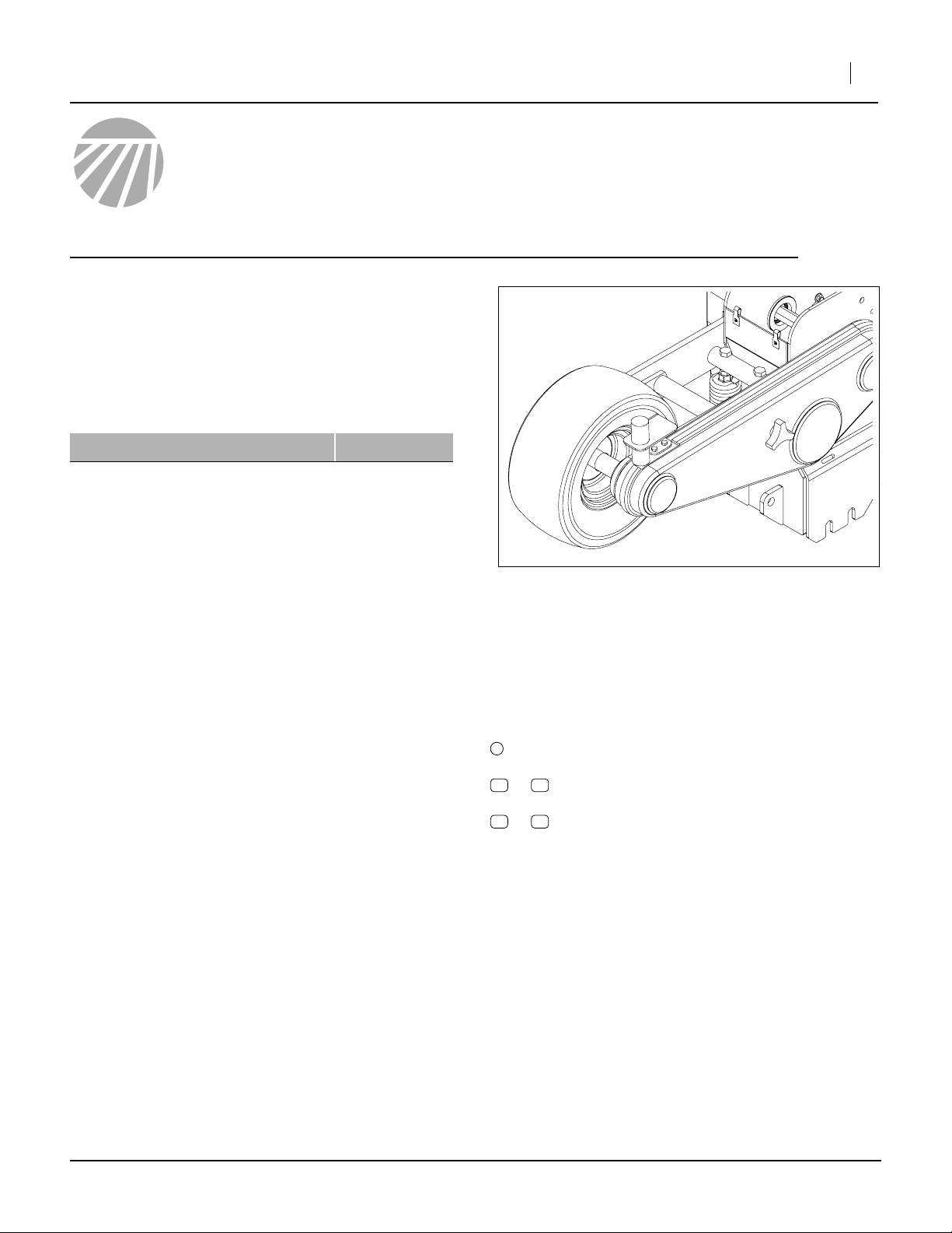
Figure 1
Sensor Installed, Cover On
“Left” and “Right” are facing in the direction of machine
travel.
1
callouts identify components in the currently
referenced Figure or Figures
11 23
to callouts reference new parts from the list on
page 9
51 63
to callouts reference existing parts from the list on
page 9.
26000
2. Power off the seed monitor.
3. Remove the seed hoppers with seed meters.
Secure the tractor.
Notations and Conventions
©Copyright 2007 Printed 02/02/2007 402-231M
2 Update Kit
Ground Drive Sensor Installation
Remove Components from Work Area
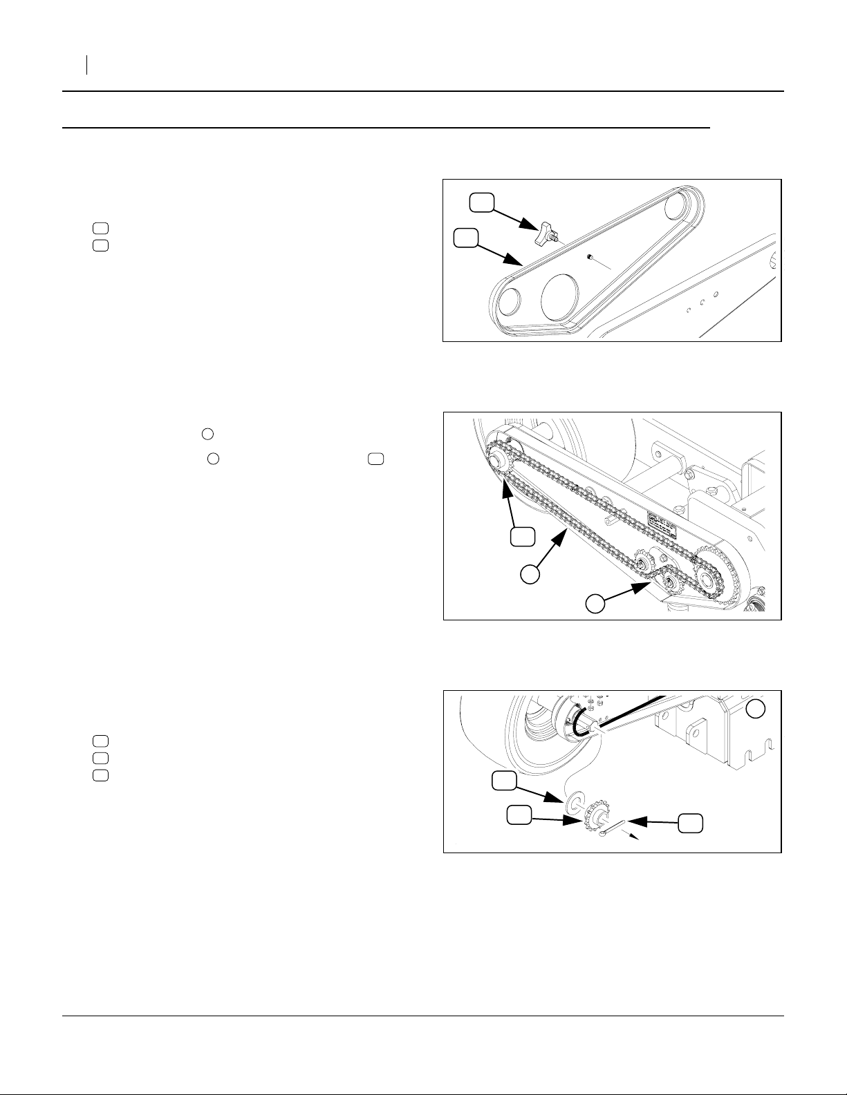
Refer to Figure 2
4. On the left hand contact drive, gain access to the
area to be updated by, removing and saving the:
60
KNOB, TRANS. SHIELD
62
LH CONTACT DRIVE CHAIN COVER
Great Plains Mfg., Inc.
60
62
Refer to Figure 3
5. Loosen the idlers .
6. Remove the chain from the drive sprocket
and let it hang toward the idlers.
Refer to Figure 4
7. At the contact wheel shaft, remove and save one
each of these existing parts:
58
PIN COTTER 1/4 X 2 PLT
59
SPKT 40C15 X 7/8 HEX BORE
57
WASHER FLAT SAE 1
1
259
Figure 2
Remove Cover
59
2
1
Figure 3
Dismount Sprocket & Washer
57
26002
16863
1
59
Figure 4
Dismount Sprocket & Washer
402-231M 02/02/2007
58
25493
Great Plains Mfg., Inc.
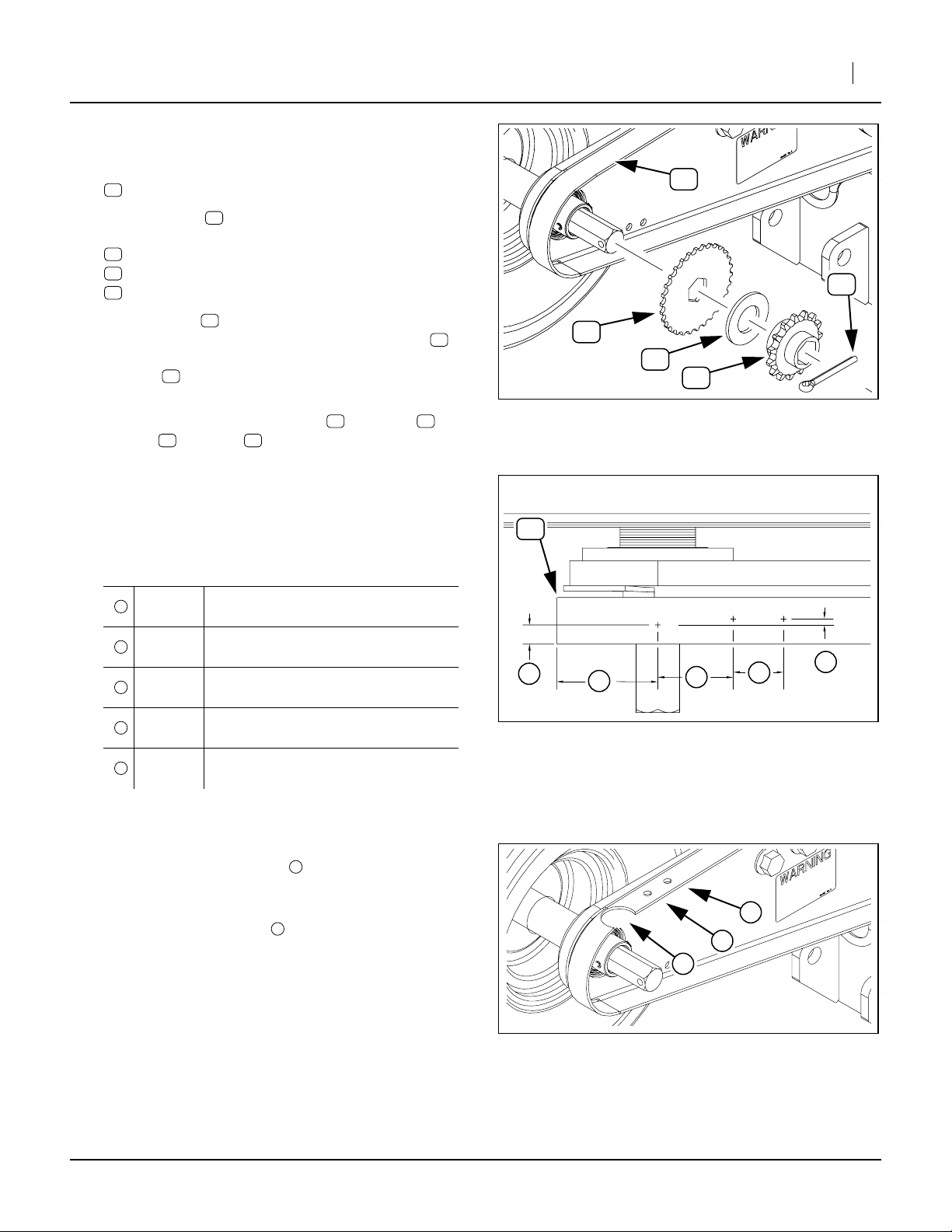
Mark for Sensor Hole
Refer to Figure 5 and Figure 6
8. Select one new:
12
402-262D DISC, MAG PICKUP
Installation Instructions 3
+
51
9. Place the disc on the shaft, and temporarily reinstall:
58
PIN COTTER 1/4 X 2 PLT
59
SPKT 40C15 X 7/8 HEX BORE
57
WASHER FLAT SAE 1
10. Slide the disc in and out on the shaft, and
determine the average position. Mark the shield
directly above the average top center position of
the disc . Compare the result to the predicted
measurements in the table at step 12.
11. Remove and save the cotter pin , sprocket ,
washer and disc .
57 12
12
12
62
12
58 59
Mark for Sensor Mount Holes
Refer to Figure 6
12. Mark for two additional holes forward and slightly to
the left of the sensor hole, as depicted in Figure 6.
Hole Placement
1
2
3
4
5
9.5mm
0.375in
51mm
2.0in
38.1mm
1.5in
25.4mm
1.0in
3.2mm
0.125in
Sensor hole to edge of shield
(approximate)
Sensor hole to end of shield
(approximate)
Sensor hole to rear mount hole
Mount hole to mount hole
Sensor/Mount centerline offset
51
1
12
57
59
Figure 5
Mark Sensor Hole
2
Mark Sensor Mount Holes
3
Figure 6
58
26003
4
5
26001
Drill Holes for Sensor Mount
Refer to Figure 7
13. Drill or cut the sensor hole to a diameter
between 32mm and 35mm. File off any sharp
edges.
1
2
14. Drill the mounting holes to diameters between
6.7mm and 7.1mm.
2
2
1
Figure 7
Cut Holes
02/02/2007 402-231M
26004
 Loading...