

Great Plains PD8070 Operator Manual
Table of Contents Index
Operator Manual
2007+ PD8070
PD8070 8-Row 70cm Pull-Type Planter
Manufacturing, Inc.
www.greatplainsmfg.com
Read the operator manual entirely. When you see this symbol, the
subsequent instructions and warnings are serious - follow without
exception. Your life and the lives of others depend on it!
25414
Illustrations may show optional equipment not supplied with standard unit or may
depict similar models where a topic is identical.
ORIGINAL INSTRUCTIONS
© Copyright 2014 Printed 2014-07-23 401-479M
Table of Contents Index
EN

Table of Contents Index
Table of Contents Index

Great Plains Manufacturing, Inc. Cover Index iii
Table of Contents
Important Safety Information ...................................... 1
Safety Decals ................................................................. 6
Introduction ................................................................10
Document Family .........................................................10
Models Covered ........................................................... 10
Intended Usage ........................................................10
Description of Unit ........................................................10
Using This Manual........................................................10
Definitions................................................................. 10
Owner Assistance ........................................................11
Product Support .......................................................11
Preparation and Setup ...............................................12
Pre-Start Checklist .......................................................12
Hitching Planter to Tractor............................................13
Hydraulic Hose Hookup................................................14
Protecting Hydraulic Motor Seals .................................14
Electrical Hookup .........................................................16
Seed Monitor Console..............................................16
Lighting Harness ......................................................16
Mate Connectors at Hitch.........................................16
Leveling Planter............................................................17
Planter Frame Height ...............................................17
Exchanging Meters.......................................................18
Installing Brush Meter Plates.................................... 19
Mud Scrapers (Optional) ..........................................20
Ridge Planting ..........................................................20
Re-Phasing Lift System................................................20
Monitor Setup ...............................................................21
Marker Setup (Option)..................................................21
Bleeding Hydraulics......................................................21
Lift Hydraulics...........................................................21
Marker Hydraulics.....................................................21
Operating Instructions...............................................22
Pre-Start Checklist .......................................................22
Transporting the PD8070 Planter.................................23
Loading Materials .........................................................24
Loading Seed ...........................................................24
Loading Fertilizer......................................................25
Seed Drive Clutch.....................................................26
Meter Clutch Disengagement ...............................26
Meter Shaft Alignment ..........................................26
Field Operation.............................................................27
Raising/Lowering Planter .............................................27
Marker Operation .........................................................28
Row Marker Operation ............................................. 28
Row Unit Operation...................................................... 28
Parking......................................................................... 29
Storage ........................................................................ 29
Adjustments ............................................................... 30
Setting Material Rates.................................................. 30
Seed Rate ................................................................ 31
Transmission Adjustment.........................................31
Checking Planting Population .................................. 32
Brush Meter Rates ................................................... 33
Reading the Brush Meter Chart ........................... 33
Brush Meter Rate Chart ........................................... 34
Finger Meter Rates .................................................. 35
Reading the Finger Meter Chart........................... 35
Finger Meter Rate Chart .......................................... 36
Dry Fertilizer Rate .................................................... 37
Fertilizer Density Adjustment ................................... 38
Fertilizer Rate Charts ............................................... 38
Dry Fertilizer Low Rate Setting ............................ 38
Dry Fertilizer High Rate Setting............................ 38
Contact Drive Tension ................................................. 39
Marker Adjustments ..................................................... 40
Marker Extension ..................................................... 40
Marker Disk Adjustments ......................................... 41
Marker Disk Angle................................................ 41
Marker Disk Angle Axis ........................................ 41
Marker Folding Speed..............................................41
Row Implement Adjustments ....................................... 42
Frame-Mounted Row Accessories ........................... 42
Terra-Tine™ Row Cleaners .................................42
Zone Coulters....................................................... 43
In-Row.................................................................. 43
Between Row (or Off-Row at least 2in)................ 43
Vantage I Frame-Mounted Coulters..................... 43
Vantage II Fertilizer Coulters................................ 44
30 Series Row Units................................................. 45
Row Unit Down Pressure ......................................... 46
Row Cleaner Adjustments........................................ 47
Coulter Adjustments.................................................48
Row-Unit Opener Adjustments................................. 49
Setting Planting Depth ......................................... 49
Disk Angle and Side Gauge Wheels .................... 49
Adjusting Disk Angle & Side Gauge Wheels........ 50
Adjusting Gauge Wheel Scrapers ........................ 51
Seed Meter Setup and Adjustment .......................... 52
Finger Meter Brush Adjustment ........................... 53
© Copyright 2006, 2007, 2008, 2010, 2011, 2012, 2014 All rights Reserved
Great Plains Manufacturing, Inc. provides this publication “as is” without warranty of any kind, either expressed or implied. While every precaution has been
taken in the preparation of this manual, Great Plains Manufacturing, Inc. assumes no responsibility for errors or omissions. Neither is any liability assumed for
damages resulting from the use of the information contained herein. Great Plains Manufacturing, Inc. reserves the right to revise and improve its products as
it sees fit. This publication describes the state of this product at the time of its publication, and may not reflect the product in the future.
2014-07-23 Cover Index 401-479M
Trademarks of Great Plains Manufacturing, Inc. include: Singulator Plus, Swath Command, Terra-Tine.
Registered Trademarks of Great Plains Manufacturing, Inc. include:
Air-Pro, Clear-Shot, Discovator, Great Plains, Land Pride, MeterCone, Nutri-Pro, Seed-Lok, Solid Stand,
Terra-Guard, Turbo-Chisel, Turbo-Chopper, Turbo Max, Turbo-Till, Ultra-Till, Verti-Till, Whirlfilter, Yield-Pro.
Brand and Product Names that appear and are owned by others are trademarks of their respective owners.
Printed in the United States of America

iv PD8070 Table of Contents Index Great Plains Manufacturing, Inc.
Finger Meter Inserts ............................................. 54
Sunflower Meter Configurations........................... 54
Seed Firmer Adjustments ........................................ 55
Keeton
®
Seed Firmer Adjustment........................ 55
Press Wheel Adjustments........................................ 55
Double-V Press Wheels ....................................... 55
Press Wheel Down Pressure ............................... 56
Press Wheel Stagger ........................................... 56
Cast Press Wheel Stagger................................... 56
Press Wheel Centering ........................................ 57
Single Press Wheel.............................................. 57
Troubleshooting......................................................... 58
Maintenance and Lubrication ................................... 61
Maintenance ................................................................ 61
General Maintenance............................................... 61
Lift Cylinder Lock-Up................................................ 62
Material Clean-Out................................................... 63
Seed Hopper Clean-Out....................................... 63
Finger Meter Clean-Out ....................................... 64
Brush Meter Clean-Out ........................................ 64
Seed Tube Clean-Out .......................................... 64
Fertilizer Hopper Clean-Out ................................. 64
Bleeding Hydraulics ..................................................... 65
Bleeding Lift Hydraulics ........................................... 65
Replacing Shear Pins and Bolts .............................. 66
Drive-Line Shear Pins .......................................... 66
Marker Shear Bolt ................................................ 66
Shaft Alignment........................................................ 67
Ratchet Drives ......................................................... 68
Chain Maintenance .................................................. 68
Chain Tension.......................................................... 69
30 Series Opener Disks and Scrapers..................... 70
30 Series Row-Unit Side Wheels............................. 71
Exchanging Finger Sets............................................... 72
Install Corn Finger Set ..........................................75
Meter Maintenance ...................................................76
Finger Meter Maintenance....................................76
Finger Set Inspection............................................76
Finger Meter Re-Assembly Steps.........................76
Precautions...........................................................76
Population Max™ Annual Maintenance................77
Population Max™ Installation ...............................77
Skip Stop™ Annual Maintenance .........................78
Skip Stop™ Installation.........................................78
Brush Meter Maintenance.........................................79
Seed Plate Maintenance...........................................80
Cleaning and Storing Seed Disks .........................80
Lubrication and Scheduled Maintenance .....................81
Options ........................................................................87
Appendix A - Reference Information ........................97
Specifications and Capacities.......................................97
Tire Inflation Chart ........................................................97
Hydraulic Diagrams ......................................................98
Lift Hydraulics ...........................................................98
Marker Hydraulics.....................................................99
Torque Values Chart ..................................................100
Appendix B - Initial Setup ........................................101
Hydraulic Charge and Bleed.......................................101
Seed Monitor Console Installation..............................101
Seed Monitor Console Quick-Start .............................101
Power-Up The Console ..........................................102
Set Metric Mode......................................................102
Set Planter Row Count ...........................................102
Set Planter Row Spacing........................................103
Row Setup ..............................................................103
Warranty .....................................................................104
Index ..........................................................................105
401-479M Table of Contents Index 2014-07-23
Great Plains Manufacturing, Inc. Table of Contents Index 1
Important Safety Information
Look for Safety Symbol
The SAFETY ALERT SYMBOL indicates there is a
potential hazard to personal safety involved and extra
safety precaution must be taken. When you see this
symbol, be alert and carefully read the message that
follows it. In addition to design and configuration of
equipment, hazard control and accident prevention are
dependent upon the awareness, concern, prudence and
proper training of personnel involved in the operation,
transport, maintenance and storage of equipment.
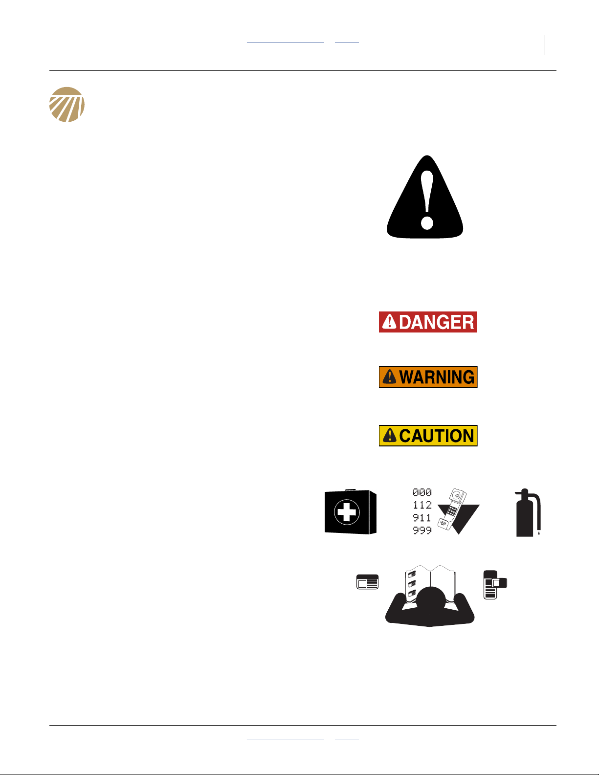
Be Aware of Signal Words
Signal words designate a degree or level of hazard
seriousness.
DANGER indicates an imminently hazardous situation
which, if not avoided, will result in death or serious injury.
This signal word is limited to the most extreme situations,
typically for machine components that, for functional
purposes, cannot be guarded.
WARNING indicates a potentially hazardous situation
which, if not avoided, could result in death or serious
injury, and includes hazards that are exposed when
guards are removed. It may also be used to alert against
unsafe practices.
CAUTION indicates a potentially hazardous situation
which, if not avoided, may result in minor or moderate
injury. It may also be used to alert against unsafe
practices.
Prepare for Emergencies
▲ Be prepared if a fire starts
▲ Keep a first aid kit and fire extinguisher handy.
▲ Keep emergency numbers for doctor, ambulance, hospital
and fire department near phone.
Be Familiar with Safety Decals
▲ Read and understand “Safety Decals” on page 6,
thoroughly.
▲ Read all instructions noted on the decals.
▲ Keep decals clean. Replace damaged, faded and illegible
decals.
2014-07-23 Table of Contents Index 401-479M

2 PD8070 Table of Contents Index Great Plains Manufacturing, Inc.
Avoid High Pressure Fluids
Escaping fluid under pressure can penetrate the skin,
causing serious injury.
▲ Avoid the hazard by relieving pressure before disconnecting
hydraulic lines.
▲ Use a piece of paper or cardboard, NOT BODY PARTS, to
check for suspected leaks.
▲ Wear protective gloves and safety glasses or goggles when
working with hydraulic systems.
▲ If an accident occurs, seek immediate medical attention
from a physician familiar with this type of injury.
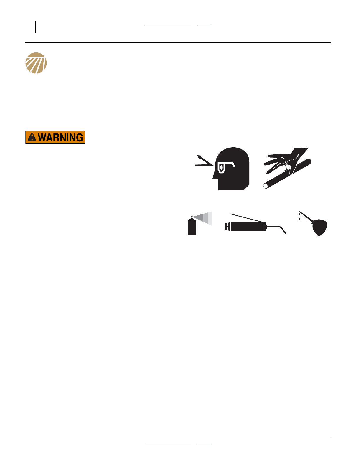
Wear Protective Equipment
Great Plains advises all users of chemical pesticides or
herbicides to use the following personal safety
equipment.
▲ Waterproof, wide-brimmed hat
▲ Waterproof apron.
▲ Face shield, goggles or full face respirator.
▲ Goggles with side shields or a full face respirator is
required if handling or applying dusts, wettable powders, or
granules or if being exposed to spray mist.
▲ Cartridge-type respirator approved for pesticide vapors
unless label specifies another type of respirator.
▲ Waterproof, unlined gloves. Neoprene gloves are
recommended.
▲ Cloth coveralls/outer clothing changed daily; waterproof
items if there is a chance of becoming wet with spray
▲ Waterproof boots or foot coverings
▲ Do not wear contaminated clothing. Wash protective
clothing and equipment with soap and water after each use.
Personal clothing must be laundered separately from
household articles.
▲ Clothing contaminated with certain pesticides must be
destroyed according to state and local regulations. Read
chemical label for specific instructions.
▲ Wear clothing and equipment appropriate for the job. Avoid
loose-fitting clothing.
▲ Prolonged exposure to loud noise can cause hearing
impairment or loss. Wear suitable hearing protection such
as earmuffs or earplugs.
▲ Avoid wearing entertainment headphones while operating
machinery. Operating equipment safely requires the full
attention of the operator.
401-479M Table of Contents Index 2014-07-23

Great Plains Manufacturing, Inc. Table of Contents Index Important Safety Information 3
Handle Chemicals Properly
Agricultural chemicals can be dangerous. Improper use
can seriously injure persons, animals, plants, soil and
property.
▲ Read and follow chemical manufacturer’s instructions.
▲ Wear protective clothing.
▲ Handle all chemicals with care.
▲ Agricultural chemicals can be dangerous. Improper use can
seriously injure persons, animals, plants, soil and property.
▲ Inhaling smoke from any type of chemical fire is a serious
health hazard.
▲ Store or dispose of unused chemicals as specified by the
chemical manufacturer.
▲ If chemical is swallowed, carefully follow the chemical
manufacturer’s recommendations and consult with a doctor.
▲ If persons are exposed to a chemical in a way that could
affect their health, consult a doctor immediately with the
chemical label or container in hand. Any delay could cause
serious illness or death.
▲ Dispose of empty chemical containers properly. By law
rinsing of the used chemical container must be repeated
three times. Puncture the container to prevent future use. An
alternative is to jet-rinse or pressure rinse the container.
▲ Wash hands and face before eating after working with
chemicals. Shower as soon as application is completed for
the day.
▲ Apply only with acceptable wind conditions. Wind speed
must be below 5 mph (8 km/h). Make sure wind drift of
chemicals will not affect any surrounding land, people or
animals.
▲ Never wash out a hopper within 100 feet (30 m) of any
freshwater source or in a car wash.
Use A Safety Chain
▲ Use a safety chain to help control drawn machinery should
it separate from tractor draw bar.
▲ Use a chain with a strength rating equal to or greater than
the gross weight of towed machinery.
▲ Attach chain to tractor draw bar support or other specified
anchor location. Allow only enough slack in chain to permit
turning.
▲ Replace chain if any links or end fittings are broken,
stretched or damaged.
▲ Do not use safety chain for towing.
2014-07-23 Table of Contents Index 401-479M
4 PD8070 Table of Contents Index Great Plains Manufacturing, Inc.
Keep Riders Off Machinery
Riders obstruct the operator’s view. Riders could be
struck by foreign objects or thrown from the machine.
▲ Never allow children to operate equipment.
▲ Keep all bystanders away from machine during operation.
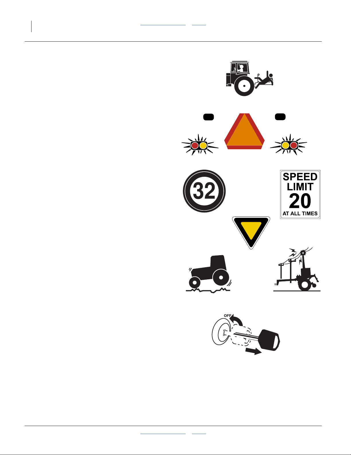
Use Safety Lights and Devices
Slow-moving tractors and towed implements can create
a hazard when driven on public roads. They are difficult
to see, especially at night.
▲ Use flashing warning lights and turn signals whenever
driving on public roads.
▲ Use lights and devices provided with implement
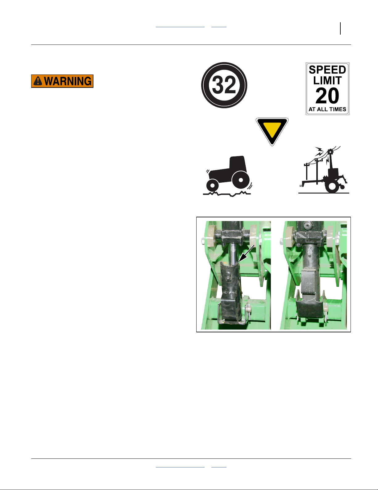
Transport Machinery Safely
Maximum transport speed for implement is 32 km/h
(20 mph). Rough terrains require a slower speed.
Sudden braking can cause a towed load to swerve and
upset.
▲ Do not exceed 32 km/h. Never travel at a speed which does
not allow adequate control of steering and stopping. Reduce
speed if towed load is not equipped with brakes.
▲ Comply with state and local laws.
▲ Do not tow an implement that, when fully loaded, weighs
more than 1.5 times the weight of towing vehicle.
▲ Carry reflectors or flags to mark planter in case of
breakdown on the road.
▲ Keep clear of overhead power lines and other obstructions
when transporting. See “Specifications and Capacities”on
page 97 for transport dimensions.
▲ Do not fold or unfold the planter while the tractor is
moving.
Shutdown and Storage
▲ Lower planter, put tractor in park, turn off engine, and
remove the key.
▲ Secure planter using blocks and supports provided.
▲ Detach and store planter in an area where children
normally do not play.
401-479M Table of Contents Index 2014-07-23

Great Plains Manufacturing, Inc. Table of Contents Index Important Safety Information 5
Tire Safety
Tire changing can be dangerous and should be
performed by trained personnel using correct tools and
equipment.
▲ When inflating tires, use a clip-on chuck and extension hose
long enough for you to stand to one side–not in front of or
over tire assembly. Use a safety cage if available.
▲ When removing and installing wheels, use wheel-handling
equipment adequate for weight involved.
Practice Safe Maintenance
▲ Understand procedure before doing work. Use proper tools
and equipment. Refer to this manual for additional
information.
▲ Work in a clean, dry area.
▲ Lower the planter, put tractor in park, turn off engine, and
remove key before performing maintenance.
▲ Make sure all moving parts have stopped and all system
pressure is relieved.
▲ Allow planter to cool completely.
▲ Disconnect battery ground cable (-) before servicing or
adjusting electrical systems or before welding on planter.
▲ Inspect all parts. Make sure parts are in good condition and
installed properly.
▲ Remove buildup of grease, oil or debris.
▲ Remove all tools and unused parts from planter before
operation.
Safety At All Times
Thoroughly read and understand the instructions in this
manual before operation. Read all instructions noted on
the safety decals.
▲ Be familiar with all planter functions.
▲ Operate machinery from the driver’s seat only.
▲ Do not leave planter unattended with tractor engine
running.
▲ Do not dismount a moving tractor. Dismounting a moving
tractor could cause serious injury or death.
▲ Do not stand between the tractor and planter during
hitching.
▲ Keep hands, feet and clothing away from power-driven
parts.
▲ Wear snug-fitting clothing to avoid entanglement with
moving parts.
▲ Watch out for wires, trees, etc., when folding and raising
planter. Make sure all persons are clear of working area.
2014-07-23 Table of Contents Index 401-479M
6 PD8070 Table of Contents Index Great Plains Manufacturing, Inc.
Safety Decals
Safety Reflectors and Decals
Your implement comes equipped with all lights, safety
reflectors and decals in place. They were designed to
help you safely operate your implement.
▲ Read and follow decal directions.
▲ Keep all safety decals clean and legible.
▲ Replace all damaged or missing decals.
▲ When ordering new parts or components, also request
corresponding safety decals.
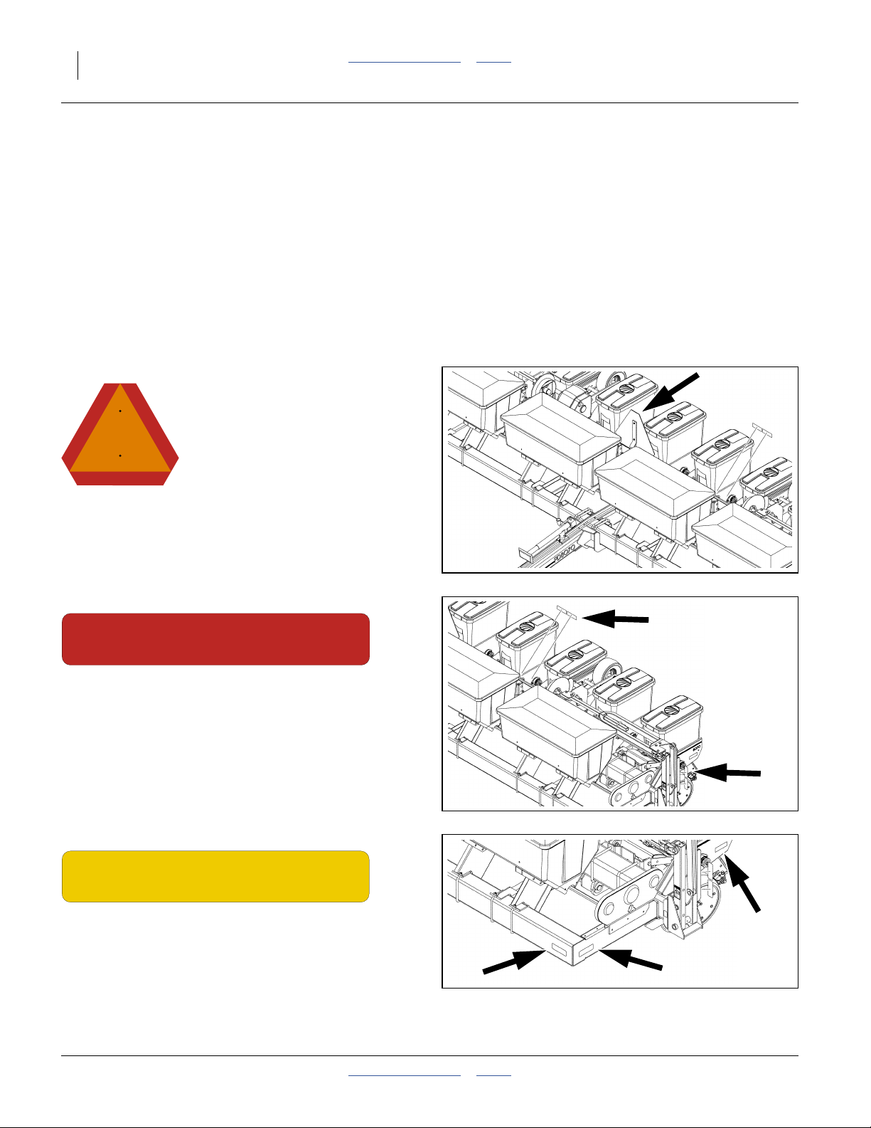
Slow Moving Vehicle Reflector
818-055C
Above main tool bar at center;
1 total
Order new decals from your Great Plains dealer. Refer to
this section for proper decal placement.
To install new decals:
1. Clean the area on which the decal is to be placed.
2. Peel backing from decal. Press firmly on surface,
being careful not to cause air bubbles under decal.
23455
Red Reflectors
838-266C
On the backside of each light mounting bar, and on the
main tool bar outboard of the inner two row units;
4 total
Amber Reflectors
838-265C
On the outside of the two outboard row units and on the
front and side at the front corners of the main frame;
6 total
23455
23455
401-479M Table of Contents Index 2014-07-23

Great Plains Manufacturing, Inc. Table of Contents Index Important Safety Information 7
Daytime Reflectors
23455
838-267C
On the backside of each light mounting bar, and on the
main tool bar outboard of the inner two row units;
4 total
Warning: Transport Speed
WARNING
EXCESSIVE SPEED HAZARD
To Prevent Serious Injury or Death:
Do Not exceed 20 mph maximum transport
speed. Loss of vehicle control and/or machine
can result.
818-188C
Right side of tongue;
1 total
818-188C Rev. C
17983
Warning: High Pressure Fluid Hazard
818-339C
On the tongue;
1 total
Warning: Sharp Object (Option)
818-525C
On each row cleaner;
8 total
17983
15732
27333
15733
2014-07-23 Table of Contents Index 401-479M
8 PD8070 Table of Contents Index Great Plains Manufacturing, Inc.
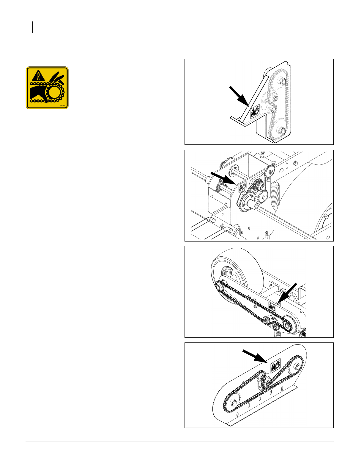
Warning: Moving Chain
838-363C
Transmission Drive (1)
Reverser Drives (2),
Contact Drives; 2 total
Dry Fertilizer Drive (1);
6 total
25445
25443
25444
25469
401-479M Table of Contents Index 2014-07-23
Great Plains Manufacturing, Inc. Table of Contents Index Important Safety Information 9
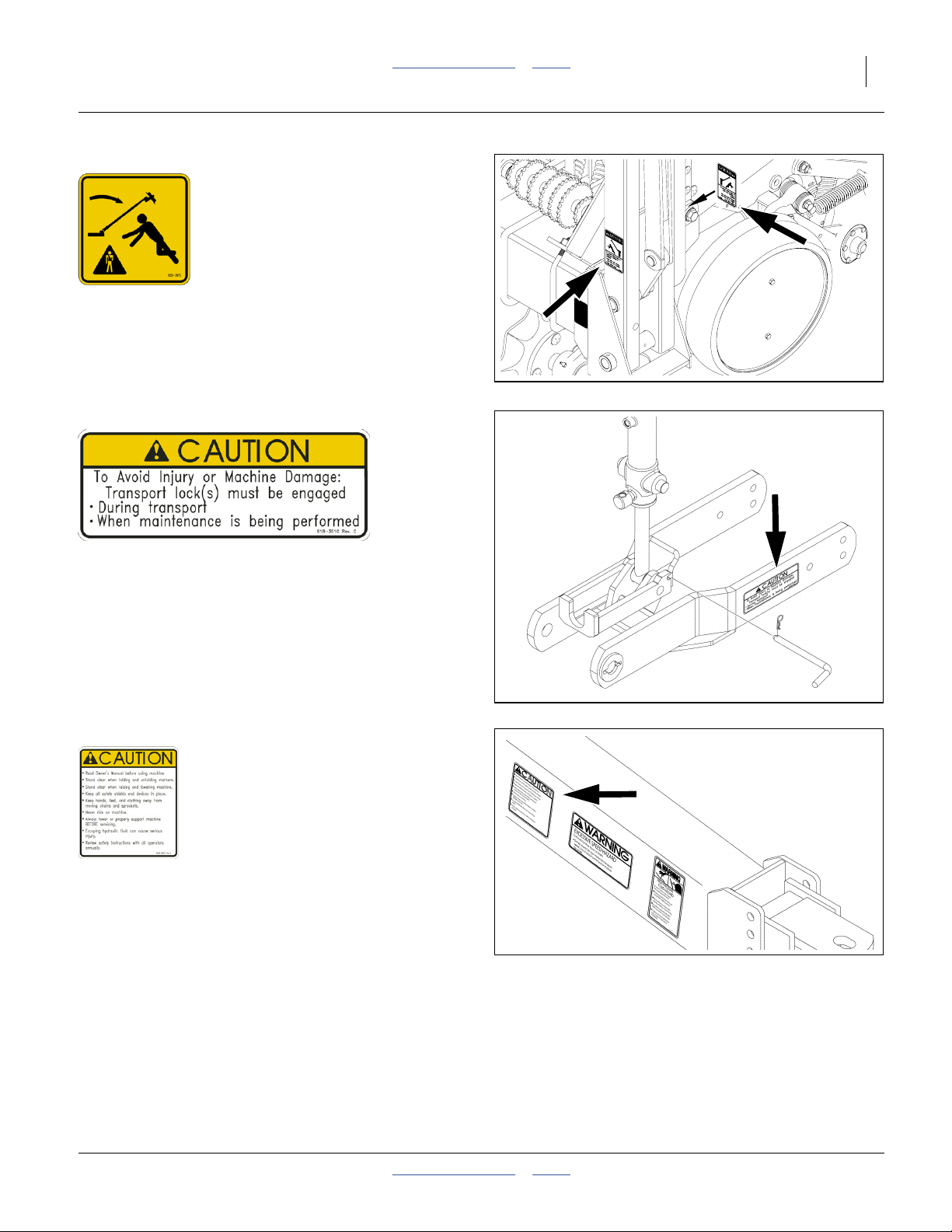
Warning: Markers Overhead
838-367C
Front and back of marker inner arms;
4 total
14914
Caution: Transport Locks
818-351C
At transport locks;
2 total
Caution: Read Operators Manual
818-587C
Right side of tongue;
1 total
25462
17983
2014-07-23 Table of Contents Index 401-479M
10 PD8070 Table of Contents Index Great Plains Manufacturing, Inc.
Introduction
Great Plains welcomes you to its growing family of new
product owners. This planter has been designed with
care and built by skilled workers using quality materials.
Proper setup, maintenance and safe operating practices
will help you get years of satisfactory use from the
machine.
Document Family
401-479M Operator/Seed Rate Manual (this manual)
401-479P Parts Manual
11001-1372 DICKEY-john® PM300 Manual
Models Covered
This manual applies to model year 2007 and later
planters. It does not apply to earlier models.
PD8070 8 ROW 70 CM PD PLANTER - 2007+
Intended Usage
Use this implement for planting row crops in large fields.
The unit is designed for conventionally tilled fields but
can be used in no-till or minimum-till conditions if
outfitted with optional tillage attachments.
Description of Unit
The 8-row, 70 cm planter is a towed precision planting
implement. The frame consists of 18×18 cm (7×7 inch)
tubing. Planting rates are adjustable by changing
sprockets on the planter transmission or contact drive.
30 Series row units are mounted on the frame with seed
hoppers standard on the row units. Springs on each row
unit provide down pressure needed for the double-disk
openers to make a seed trench.
Finger-pickup or brush meters singulate and dispense
seed from the hopper and deliver it to the trench. A dry
fertilizer hopper is standard.
Using This Manual
This manual will familiarize you with safety, assembly,
operation, adjustments, troubleshooting and
maintenance. Read this manual and follow the
recommendations to help ensure safe and efficient
operation.
The information in this manual is current at printing.
Some parts may change to assure top performance.
R
L
R
F
25414
U
B
L
D
Figure 1
Left / Right Notation
Definitions
The following terms are used throughout this manual.
Right-hand and left-hand as used in
this manual are determined by facing
the direction the machine will travel
while in use unless otherwise stated.
An orientation rose in some line art
illustrations shows the directions of:
Up, Back, Left, Down, Front, Right.
A crucial point of information related to the preceding topic.
For safe and correct operation, read and follow the directions
provided before continuing.
Note: Useful information related to the preceding topic.
401-479M Table of Contents Index 2014-07-23
Great Plains Manufacturing, Inc. Table of Contents Index Introduction 11
Owner Assistance
If you need customer service or repair parts, contact a
Great Plains dealer. They have trained personnel, repair
parts and equipment specially designed for Great Plains
products.
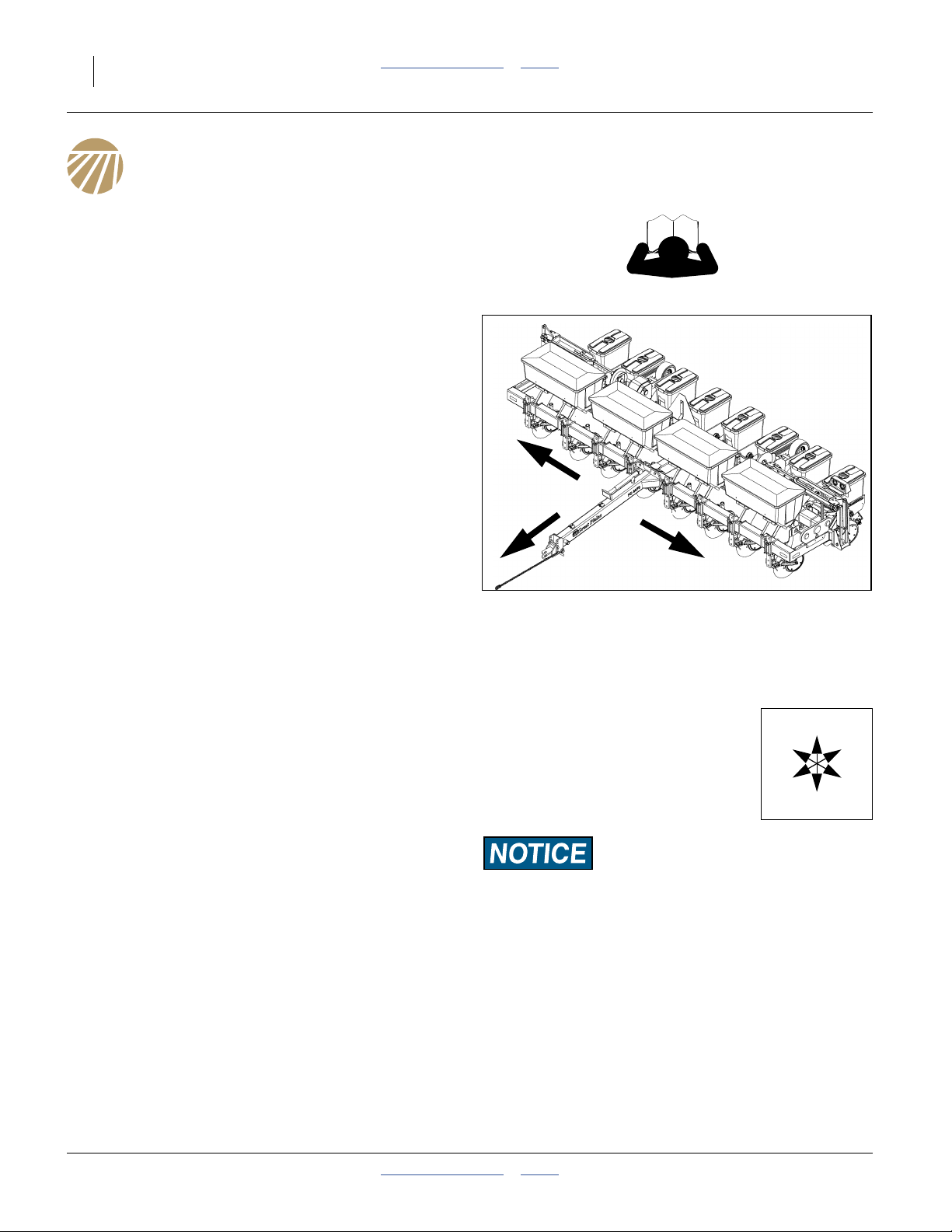
Refer to Figure 2
Your machine’s parts were specially designed and
should only be replaced with Great Plains parts. Always
use the serial and model number when ordering parts
from your Great Plains dealer. The serial-number plate is
located on the left end of the seed cart tool bar, as
shown.
Record your PD8070 Planter model and serial number
here for quick reference:
Model Number:__________________________
Serial Number: __________________________
Your Great Plains dealer wants you to be satisfied with
your new machine. If you do not understand any part of
this manual or are not satisfied with the service received,
please take the following actions.
1. Discuss the matter with your dealership
service manager. Make sure they are aware
of any problems so they can assist you.
2. If you are still unsatisfied, seek out the owner
or general manager of the dealership.
For further assistance write to:
Figure 2
Serial Number Plate
23054
Product Support
Great Plains Mfg. Inc., Service Department
PO Box 5060
Salina, KS 67402-5060
785-823-3276
2014-07-23 Table of Contents Index 401-479M
12 PD8070 Table of Contents Index Great Plains Manufacturing, Inc.
Preparation and Setup
This section helps you prepare your tractor and planter
for use. Before using the planter in the field, you must
hitch the planter to a suitable tractor and level the
planter.
Pre-Start Checklist
1. Read and understand “Important Safety
Information” on page 1.
2. Check that all working parts are moving freely, bolts
are tight, and cotter pins are spread.
3. Check that all grease fittings are in place and
lubricated. See “Lubrication and Scheduled
Maintenance” on page 81.
4. Check that all safety decals and reflectors are
correctly located and legible. Replace if damaged.
See “Safety Decals” on page 6.
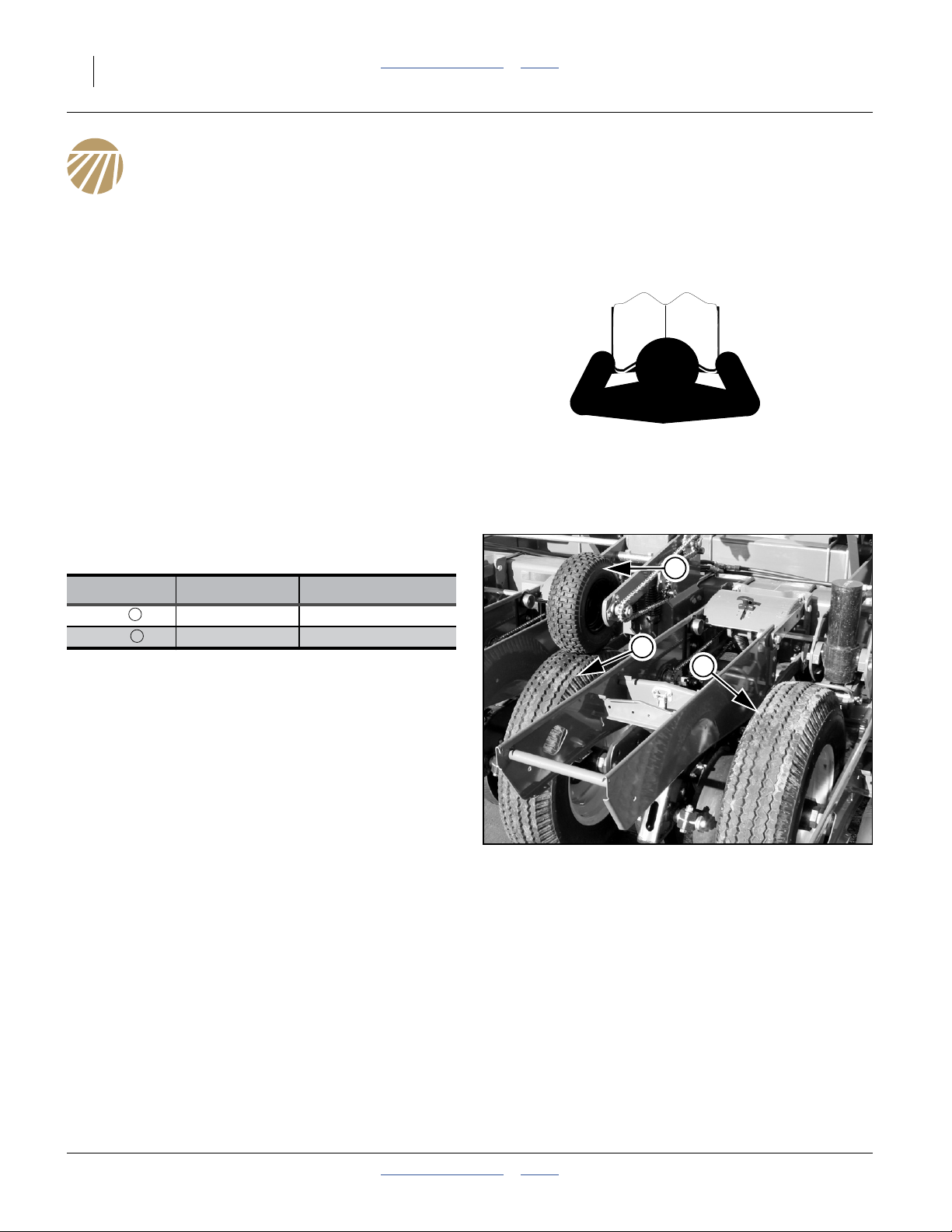
Inflate tires (Refer to Figure 3) as recommended in the
table. below.
2
Tire Size
Ground 7.00-15 LT 414 kPa (60 psi)
Contact 13-5.0 × 6 276 kPa (40 psi)
1
2
Pressure
1
1
Figure 3
Ground & Contact Tires
401-479M Table of Contents Index 2014-07-23
25446
Great Plains Manufacturing, Inc. Table of Contents Index Preparation and Setup 13
Hitching Planter to Tractor
Crushing Hazard:
You may be several injured or killed by being crushed between
the tractor and planter. Do not stand or place any part of your
body between planter and moving tractor. Stop tractor engine
and set park brake before installing hitch pin.
1. To prevent soil compaction on rows, set tractor
wheels between rows. For hillsides and steep
slopes, set tractor wheels as wide as possible for
maximum stability.
Refer to Figure 4
2. Use jack to raise and lower planter tongue.
3
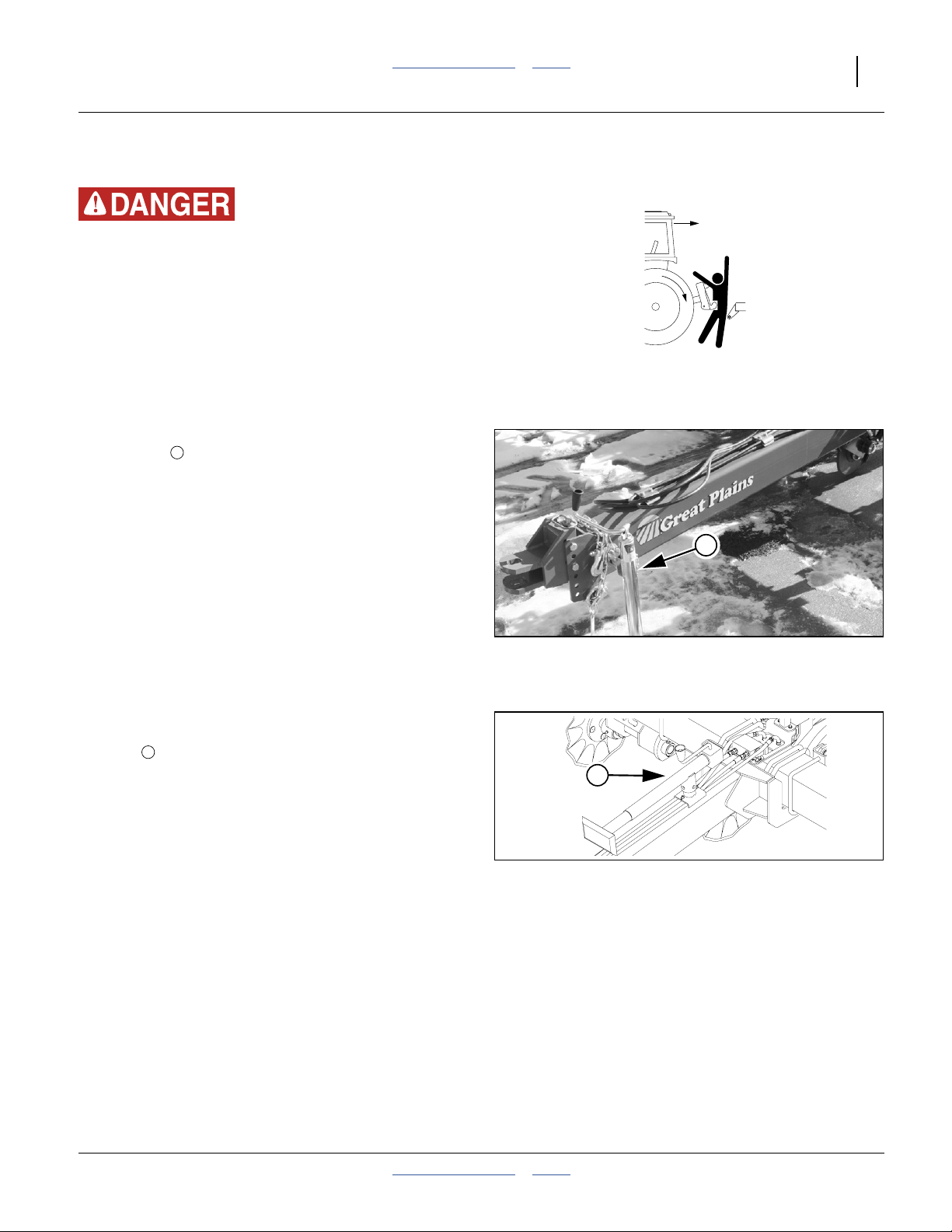
Refer to Figure 5
3. After hitching tractor to planter, store jack on storage
4
tube on top of planter tongue.
4. Secure planter safety chain to an anchor on the
tractor capable of pulling the unit.
Tongue on Jack
4
Jack in Storage
3
Figure 4
Figure 5
25447
17930
2014-07-23 Table of Contents Index 401-479M

14 PD8070 Table of Contents Index Great Plains Manufacturing, Inc.
Hydraulic Hose Hookup
High Pressure Fluid Hazard:
Escaping fluid under pressure can have sufficient pressure to
penetrate the skin causing serious injury. Avoid the hazard by
relieving pressure before disconnecting hydraulic lines. Use a
piece of paper or cardboard, NOT BODY PARTS, to check for
leaks. Wear protective gloves and safety glasses or goggles
when working with hydraulic systems. If an accident occurs,
seek immediate medical attention from a physician familiar
with this type of injury.
Only trained personnel should work on system hydraulics!
Protecting Hydraulic Motor Seals
Low Pressure (Case) Drain Connection
Motor Seal Damage Risk:
Case Drain Hose must be attached prior to inlet and return
hoses being connected. Also, it must be unhooked last to
prevent damage to the fan motor.
1. Attach case drain hose to low pressure drain
connection.
Note: Case drain hose must be hooked up first. Also, it
must be unhooked last to prevent damage to
hydraulic motor seals.
2. Connect low pressure return hose to low pressure
return connector.
Hydraulic Motor Performance Risk:
DO NOT hook case drain line to a “power-beyond port”.
3. If the tractor has a limited number of remotes
capable of continuous flow, use one for the fan. (See
“Specifications and Capacities” on page 97 for
tractor requirements.)
401-479M Table of Contents Index 2014-07-23
Great Plains Manufacturing, Inc. Table of Contents Index Preparation and Setup 15
Current Style Color Coded Hose Handles
Great Plains hydraulic hoses have color coded handle
grips to help you hookup hoses to your tractor outlets.
Hoses that go to the same remote valve are marked
with the same color.
Color Hydraulic Function
Blue Lift Cylinders
Green Marker Cylinders
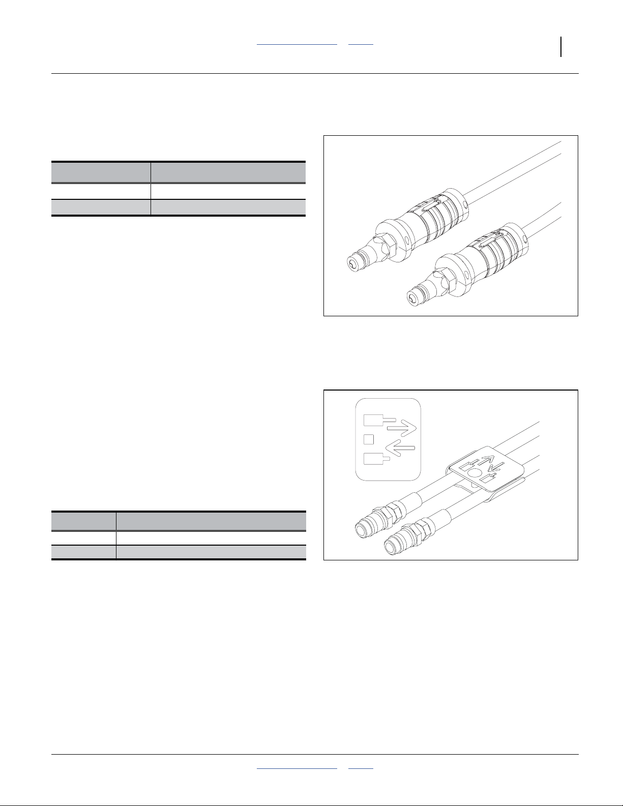
Refer to Figure 6
To distinguish hoses on the same hydraulic circuit, refer
to the symbol molded into the handle grip. Hoses with
an extended-cylinder symbol feed cylinder base ends.
Hoses with a retracted-cylinder symbol feed cylinder
rod ends.
For hydraulic fan and drive motors, connect the hose
under the retracted cylinder symbol to the pressure side
of the motor. Connect the hose under the extended
cylinder symbol to the return side of the motor.
The fan motor further requires hookup of a (third) case
drain line, which returns lubricating/cooling fluid.
Figure 6
Current Color Coded Hose Grips
31733
Older Style Hoses with Color Ties
Refer to Figure 7
Each hose set has a label for flow conventions. The label
uses cylinder Base/Extend and Rod/Retract icons.
Be sure to connect these to the matching tractor
remotes, so that remote levers are activated as
described in this manual.
Hoses that go to the same remote valve are marked with
the same color tie.
Color Hydraulic Function
Blue Lift Cylinders
Orange Marker Cylinders
Figure 7
Older Style Hoses with Label
27270
2014-07-23 Table of Contents Index 401-479M
16 PD8070 Table of Contents Index Great Plains Manufacturing, Inc.
Electrical Hookup
Seed Monitor Console
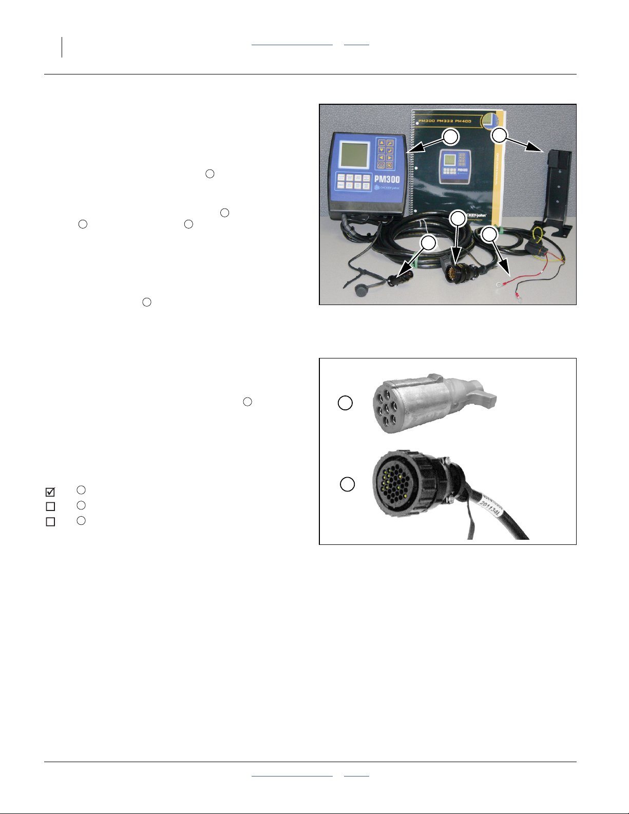
Refer to Figure 8
If the planter is equipped with one of the two optional
seed monitors, the PM300 console needs to be
mounted in the cab of the tractor to be used with the
planter.
The monitor includes cables for power , speed
sensor and sensor harness . Installation
instructions are found in the included DICKEY-john
manual.
Power color code is:
+ positive: red
- negative: black
The included bracket requires customer-supplied
fasteners.
3 4
5
1
2
®
Lighting Harness
Refer to Figure 9
The standard PD8070 Planter lighting harness is
terminated with an ASAE J560b receptacle . If your
tractor has a European style 7-pin connector, your dealer
can assist with replacing the planter connector.
1
1
5
4
2
3
Figure 8
PM300 Tractor Components
28138
1
Mate Connectors at Hitch
After installing any console or connector required, plug
and secure the connectors at the hitch.
Lights
1
DICKEY-john® Planter Control
2
___________________________
3
Make sure tractor is shut down with accessory power off
before making connections. Make all connections prior to
planter movement.
2
Figure 9
Connector Identification
25236
34574
401-479M Table of Contents Index 2014-07-23
Great Plains Manufacturing, Inc. Table of Contents Index Preparation and Setup 17
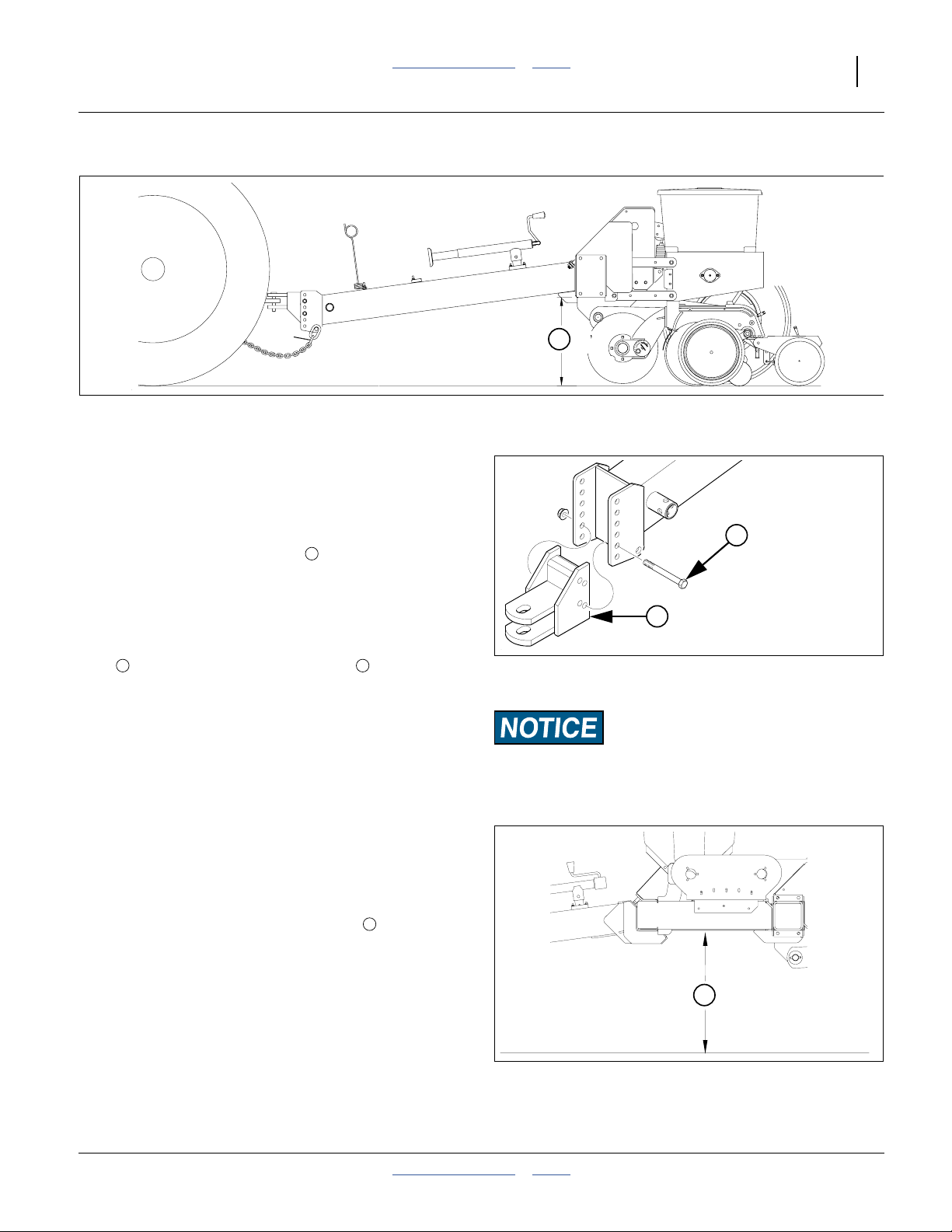
Leveling Planter
5
Figure 10
Setting tool bar Height
Refer to Figure 10
During initial setup and periodically throughout the
season, check that the planter runs level. When planting,
the top of the hopper support panel should be parallel to
the ground as shown.
To level the planter, the distance from bottom of the
mainframe tube to the ground, must be:
between 51 and 56 cm (20 and 22 inches)
with the planter lowered into planting position.
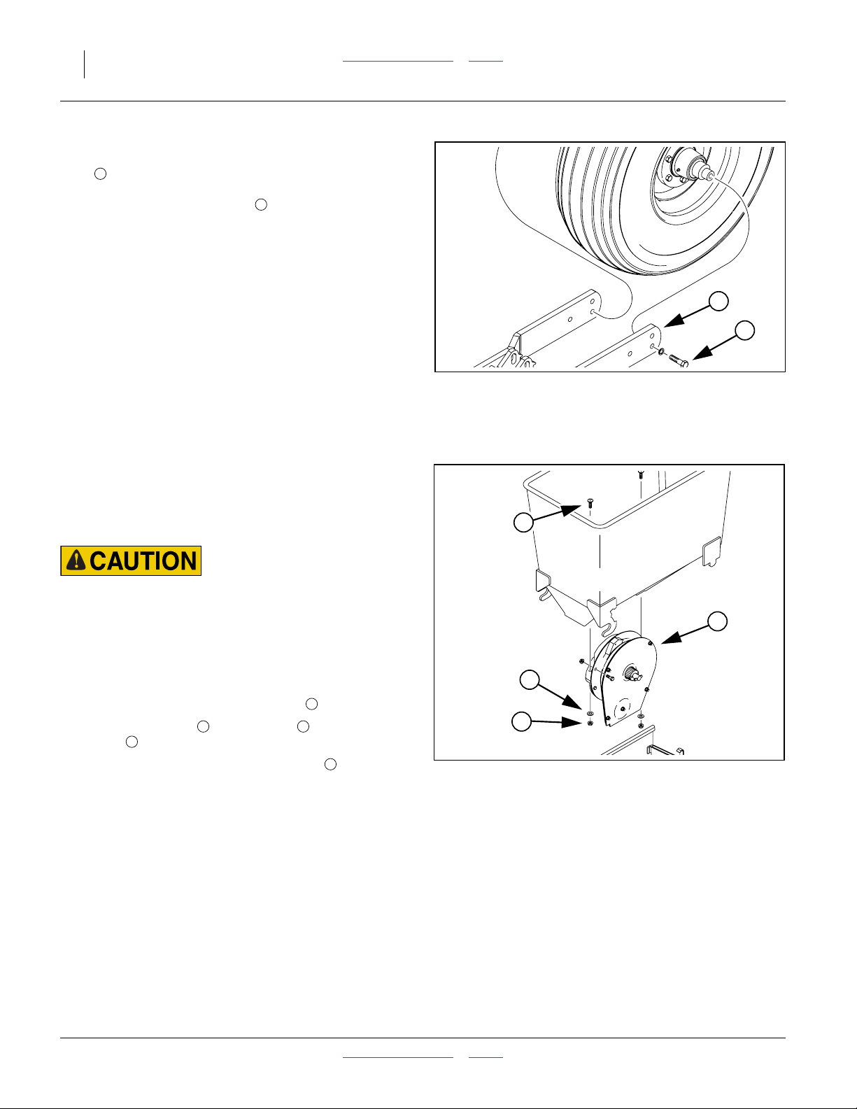
Refer to Figure 11
To obtain the correct height, remove the two hitch
6 7
bolts , and reposition the planter hitch on the
tongue.
The hitch can be turned over for extreme height
changes.
5
Planter Frame Height
Refer to Figure 12
It may be necessary to adjust planter frame height when
leveling the planter.
Lower planter to planting position.
For proper planter frame height, distance from bottom
of frame tube to ground should measure:
51 and 56 cm (20 and 22 inches)
from ground.
5
6
7
Figure 11
Hitch Height Adjustment
Equipment Damage Risk:
Always have two bolts through both hitch and tongue.
Do not rely on a single bolt.
5
24009
16865
Figure 12
Frame Height
2014-07-23 Table of Contents Index 401-479M
16865
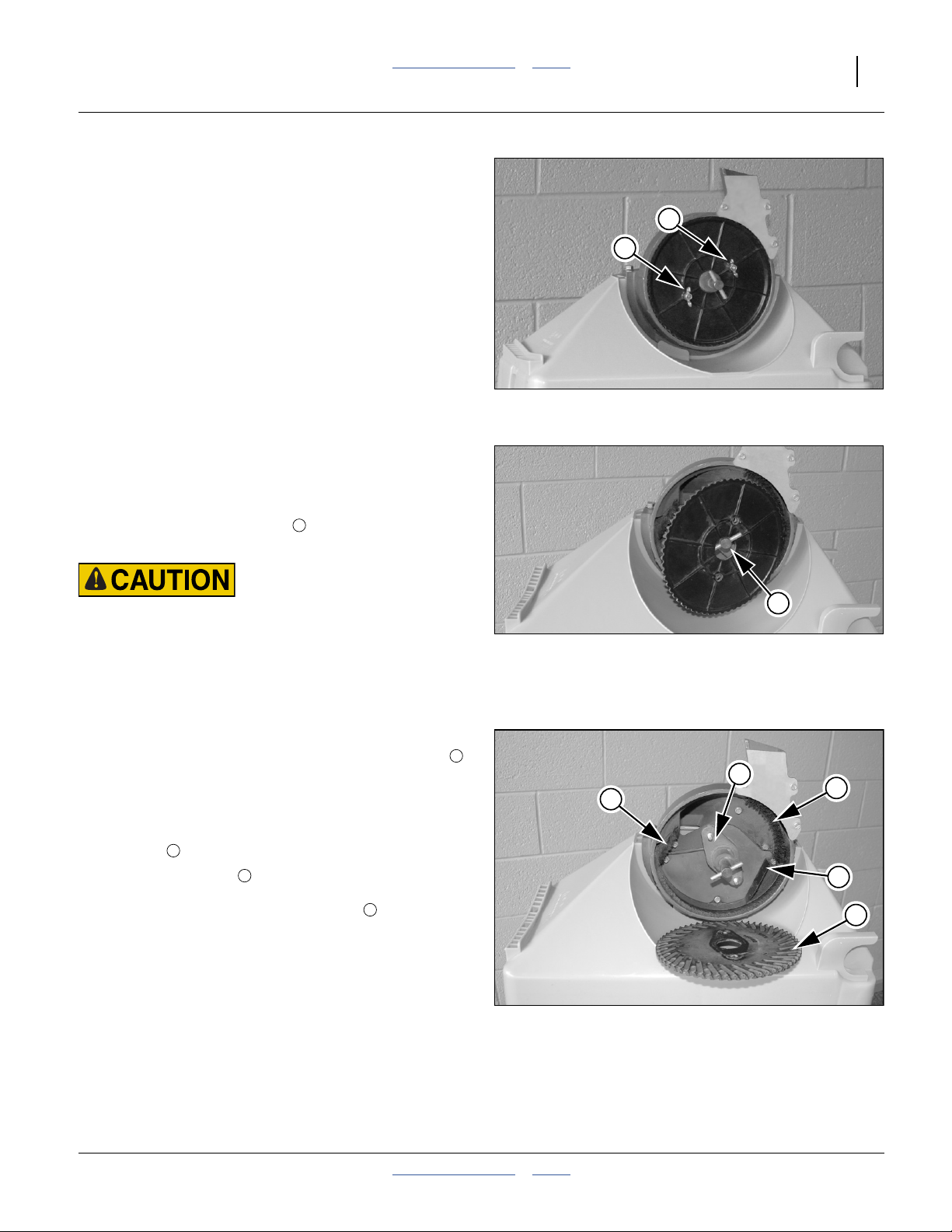
18 PD8070 Table of Contents Index Great Plains Manufacturing, Inc.
If necessary adjust planter frame height to achieve
51 and 56 cm (20 and 22 inches) from ground. Remove
8
bolts , located in lower holes, securing transport
ground tire assembly to unit. Move tire assembly and
secure assembly to upper hole using previously
removed bolt.
9
9
8
Exchanging Meters
These steps are only for changing between finger pickup
and brush meters, or vice versa. Changing seed plates
(page 19) does not require meter removal.
Agricultural Chemical Hazard:
Follow material supplier recommendations carefully. Handle
the meter as if it were treated seed. use supplier-recommended
cleaning agents. Any seed treatment build-up inside a meter is
likely to be at a higher concentration than on the actual seed.
Refer to Figure 14
1. Remove and empty the seed hopper (page 63). Put
the lid back on to capture any bolts that fall away.
2. Remove two nuts and washers . Remove the
meter .
3. Install new meter. Tighten5⁄16-18 nuts to Grade 2
torque specification. Do not over-tighten, or you may
damage the hopper. Re-install the hopper (page 24).
4. Clean and dry removed meters. See “Meter
Maintenance” on page 72.
5. Store removed meters in pest-proof containers, such
as plastic bags.
See also “Exchanging Finger Sets” on page 75.
4
2 3
1
2
Figure 13
Ground Wheel Height
1
3
2
Figure 14
Removing Meter
25448
4
25459
401-479M Table of Contents Index 2014-07-23
Great Plains Manufacturing, Inc. Table of Contents Index Preparation and Setup 19
Installing Brush Meter Plates
A selection of seed plates are available for the brush
meter (see “Seed Plates” on page 94). Use a seed plate
specific to the crop, seed variety, and seed rate range.
If the seed plates (or meters) need to be changed,
perform this operation before loading seed.
1. Select 8 of the next seed plates to install. Check that
they are all for the correct seed, seed variety and cell
count. To aid in identification, there is a table of plate
characteristics on page 94.
2. If seed is already loaded, see “Material Clean-Out”
on page 63.
3. If changing from finger pickup to brush meter, see
“Meter Maintenance” on page 72.
Refer to Figure 15
4. Uncouple the meter drive (page 26), release the
hopper latch (page 63), and remove each hopper
from its row unit.
5. Remove the two wing nuts that secure the seed
plate to the meter shaft.
1
Brush Meter Plate Wing Nuts
1
1
Figure 15
28126
Treated Seed Hazard:
Follow material supplier recommendations carefully. Handle
the meter and plate as if they were treated seed. Use
supplier-recommended cleaning agents.Any seed treatment
build-up inside a meter is likely to be at a higher concentration
than on the actual seed.
Refer to Figure 16
6. Pull the plate off the threaded studs, and angle one
side of the center hole over one end of the roll pin
in the drive shaft.
Refer to Figure 17
7. With the seed plate removed, clean any debris from
inside the meter, and inspect the condition of the
brushes . See page 79.
8. Select a new plate . Inspect the cells for any
damage, and make sure the inside surface is clean,
so that it will seat full on the disc hub .
9. Orient the plate with the cell side (not the spoke side)
toward the meter shaft. Reversing the removal
process above, angle the hole over end of the drive
shaft roll pin, then the other end, and seat the plate
on the threaded studs. Secure with wing nuts.
10. Spin the plate by hand, counter-clockwise, to verify
that it sits flush and does not wobble.
11. Re-mount the hopper on the row unit and secure
with latch.
3
3
4
2
Figure 16
Brush Meter Plate Removal
2
28127
4
3
3
3
5
Figure 17
Brush Meter Inspection
28128
2014-07-23 Table of Contents Index 401-479M
20 PD8070 Table of Contents Index Great Plains Manufacturing, Inc.
Mud Scrapers (Optional)
Refer to Figure 18
The mud scraper removes build-up that might interfere
with contact drive wheel rotation and planting depth.
1. Loosen bolts and .
2. Pivot the scraper around bolt until the clearance
4
between the scraper and tire is 3 to 6 mm
(1⁄8to1⁄4inch).
3. Tighten bolts.
1
2 3
2
4
1
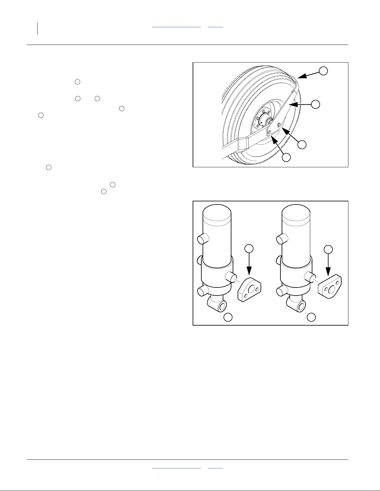
Ridge Planting
To prepare the planter for ridge planting, you must lower
the gauge wheels by inverting the cylinder mounting
blocks .
Refer to Figure 19
Standard planting is shown at .
Ridge planting is shown at .
1. Block up the frame to remove weight from tires.
2. At each of the four lift cylinders, remove the
3. Invert mounting blocks and reinstall cap screws.
1
2
3
four5⁄8inch cap screws attaching the mounting
blocks to the frame.
Torque to specification as listed on the “Torque
Values Chart” on page 100.
Re-Phasing Lift System
In typical use during a single planting operation, it is
normal for the lift cylinders to get out of phase, resulting
in uneven raising and lowering of the PD8070 Planter.
Every 8- to 10 passes, re-phase the cylinders with this
procedure:
1. Raise the planter completely, and hold the hydraulic
lever or switch in Retract for several seconds after
the planter reaches full elevation, or until all cylinders
are fully retracted.
2. When all cylinders are fully retracted, momentarily
reverse (Extend) the control to lower the planter
12 mm (1⁄2inch).
3
2
Figure 18
Gauge Wheel Mud Scraper
1
Figure 19
Cylinder Mounting Blocks
25484
1
32
14958
401-479M Table of Contents Index 2014-07-23

Great Plains Manufacturing, Inc. Table of Contents Index Preparation and Setup 21
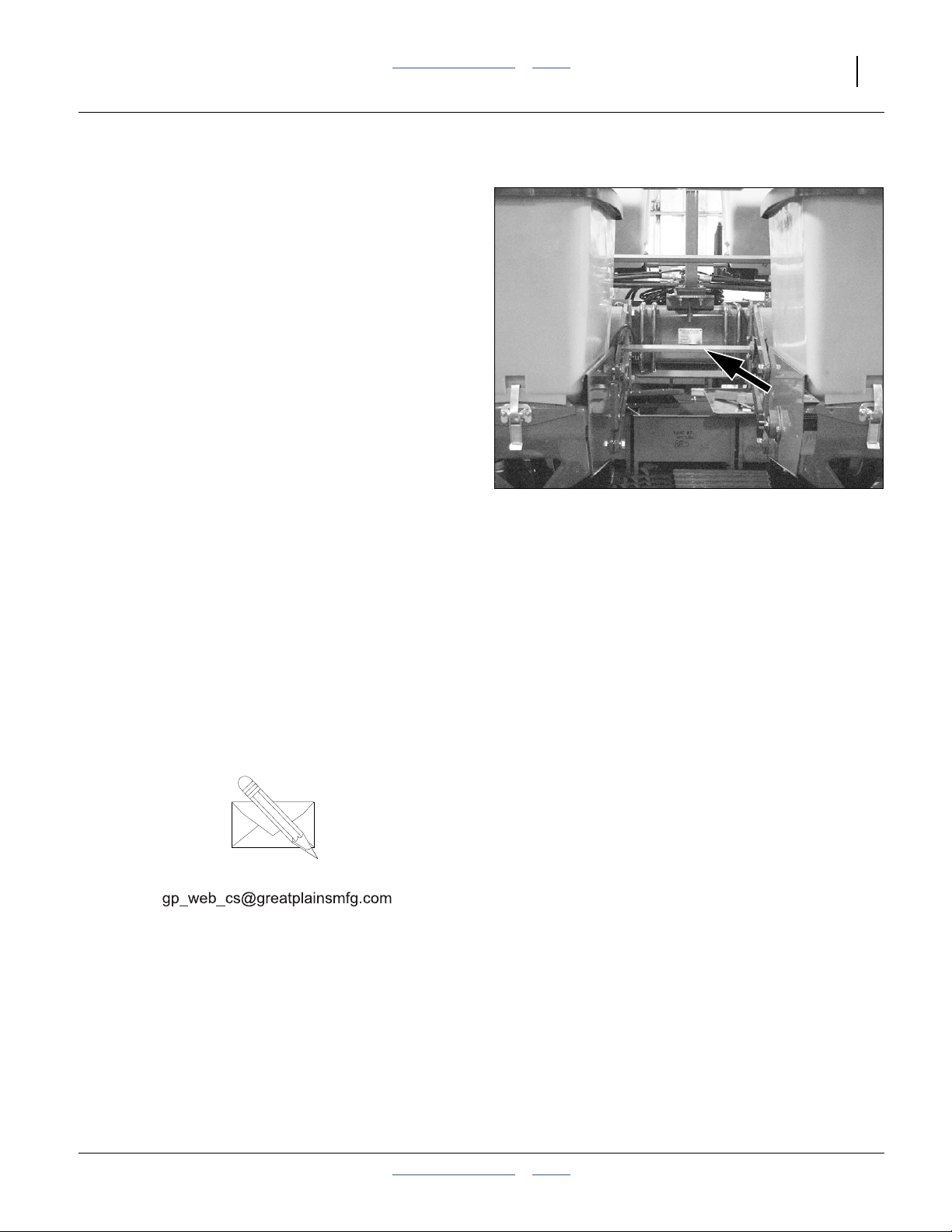
Monitor Setup
Refer to Figure 20
The standard DICKEY-john® PM300 system monitors
the following elements of a PD8070 planter:
• seeds at each row unit seed tube;
• ground speed.
See “Seed Monitor Console Installation” on page 101.
Refer to the DICKEY-john® PM300 Manual
(11001-1372) for monitor operations.
After installation, and prior to first field use, the monitor
must be setup with the row spacing and speed sensor
constant, as well as your preferences for information
display. Row count is auto-assigned, but any other
DICKEY-john
your planter.
Row spacing data may be found in the Appendix.
For speed setup, Great Plains recommends using the
122 m (400-foot) speed calibration described in the
DICKEY-john® manual. Perform the calibration run in
representative field conditions, as soil conditions, surface
looseness and other tillage practices can cause
variations in the effective rolling radius of the ground
drive wheel.
Prior to each planting session, set any desired limits for
speed and population for the current crop.
®
defaults are not likely to be correct for
Figure 20
Monitor Primary Screen
29971
Marker Setup (Option)
Prior to first use, check and adjust:
•“Marker Folding Speed” on page 41.
Prior to first use, and whenever changing row spacings,
set or reset:
•“Marker Extension” on page 40.
Prior to each planting session, check and adjust:
•“Marker Disk Adjustments” on page 41.
Bleeding Hydraulics
Lift Hydraulics
Normally the lift hydraulics are bled at the factory before
shipping, and bleeding should not be required other than
to raise fully and hold lever on for one minute or until all
cylinders extend fully.
If it is necessary to further bleed lift system, see
“Bleeding Lift Hydraulics” on page 65.
2014-07-23 Table of Contents Index 401-479M
Marker Hydraulics
To fold properly, the marker hydraulics must be free of
air. If the markers fold in jerky, uneven motions.
As the marker cylinders are encased within the main
tool bar, it is not practical to bleed them at cylinder
fittings. Remove air from the system by slowly cycling
fold and unfold several times.
22 PD8070 Table of Contents Index Great Plains Manufacturing, Inc.
Operating Instructions
This section covers general operating procedures.
Experience, machine familiarity and the following
information will lead to efficient operation and good
working habits. Always operate farm machinery with
safety in mind.
Pre-Start Checklist
High Pressure Fluid Hazard:
Escaping fluid under pressure can have sufficient pressure to
penetrate the skin. Check all hydraulic lines and fittings before
applying pressure. Fluid escaping from a very small hole can
be almost invisible. Use paper or cardboard, not body parts,
and wear heavy gloves to check for suspected leaks. If injured,
seek immediate medical attention from a physician familiar
with this type of injury.
1. Carefully read “Important Safety Information” on
page 1.
2. Lubricate planter as indicated under “Lubrication
and Scheduled Maintenance” on page 81.
3. Check all tires for proper inflation. See “Tire
Inflation Chart” on page 97.
4. Check all bolts, pins and fasteners. Torque as shown
in “Torque Values Chart” on page 100.
5. Check planter for worn or damaged parts. Repair or
replace parts before going to the field.
6. Check that hoppers are free of dirt and debris. Turn
meter-drive shaft by hand to be sure drive shaft and
seed meter turn freely.
401-479M Table of Contents Index 2014-07-23
Great Plains Manufacturing, Inc. Table of Contents Index Operating Instructions 23
Transporting the PD8070 Planter
Loss of Control Hazard:
Do not exceed 32 km/h (20 mph). Towing the planter at high
speeds can lead to loss of vehicle control. Loss of vehicle
control can lead to serious road accidents, injury, and death.
Before transporting the planter, check and practice the
following items.
1. Check that planter is securely hitched to a sufficient
tractor. Refer to Tractor Requirements, at
“Specifications and Capacities” on page 97.
2. Always use a locking-style hitch pin sized to match
holes in hitch and draw bar (minimum
1-inch-diameter, heat-treated pin).
3. Attach safety chain to tractor with enough slack to
permit turning. See “Hitching Planter to Tractor”on
page 13.
4. Verify correct operation of lights.
5. Fold markers.
6. Raise planter. Install cylinder lock-up channels on lift
assists. See “Lift Cylinder Lock-Up” on page 62.
7. Unload hoppers before transporting if at all possible.
The planter can be transported with full hoppers, but
the added weight will increase stopping distance and
decrease maneuverability.
8. Check that tires are properly inflated. See “Tire
Inflation Chart” on page 97.
9. Do not exceed 32 km/h (20 mph). Comply with all
national, regional and local laws when traveling on
public roads.
10. Remember that the planter is wider than the tractor.
Allow safe clearance.
11. Transport slowly over uneven or rough terrain.
Figure 21
Lift Cylinder Lock
31859
2014-07-23 Table of Contents Index 401-479M
24 PD8070 Table of Contents Index Great Plains Manufacturing, Inc.
Loading Materials
Loading Seed
1. Check that correct meters are installed. See “Meter
Maintenance” on page 72.
2. For brush meters, install correct seed plates. See
“Installing Brush Meter Plates” on page 19.
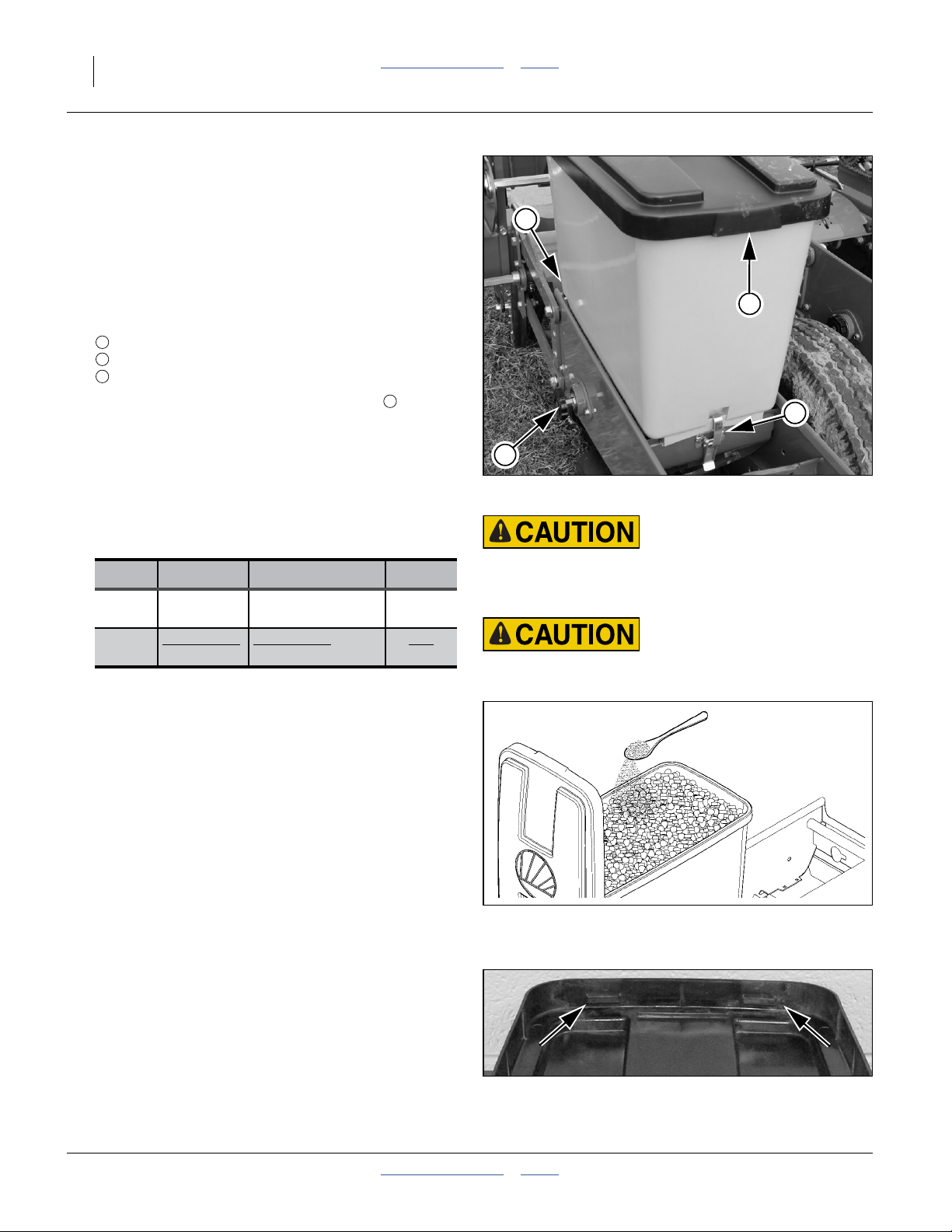
Refer to Figure 22
3. Check that hopper is correctly seated and secured:
1
pivot hooks engage at front,
2
meter clutch engages properly at side, and;
3
latch engaged at rear.
4. Remove lid by pulling back and up at rear . The lid
has a hook at inside center for parking it on the front
of the hopper during fill.
5. Inspect the hopper for leftover seed and debris.
Clean out anything other than the seed to be
planted. In particular, incompatible seed can clog
meters. See “Material Clean-Out” on page 63.
6. Have seed lubricant at hand:
4
Meter Lubricant Qty per Hopper Method
Finger
Pickup
Brush Graphite or
Refer to Figure 23
7. Add seed and lubricant:
Graphite: Fill hopper with seed.
Graphite 5 ml (1 tsp)
5 ml (1 tsp)
Talc
Sprinkle graphite on top.
(If you find that the graphite is being
depleted before the hopper empties, add it
around the top edge of the seed, rather
than at center.)
118 ml (1⁄2cup)
To p
Top
Mix
1
4
3
2
Figure 22
Seed Hopper Mounted
Agricultural Chemical Hazard:
Read and follow all supplier cautions for safe handling of
treated seed.
Do not mix lubricants into seed with hands or any part of
body.
28130
Talc Fill hopper halfway.
Add half the talc. Mix thoroughly.
Fill hopper with seed.
Add half the talc. Mix thoroughly.
For ordering, see “Seed Lubricants” on page 87.
Refer to Figure 24
8. With lid tilted forward at a slight angle, hook the two
front hinge lugs under the hopper lip. Swing down,
keeping fingers clear of lug, and latch the single rear
lid lug on rear hopper lip. Check that all 3 lid lugs are
completely under the hopper lip, or the lid may come
off in transport.
401-479M Table of Contents Index 2014-07-23
Adding Graphite Lubricant
Hopper Lid Front Hinge Lugs
Figure 23
Figure 24
15782
28131
Great Plains Manufacturing, Inc. Table of Contents Index Operating Instructions 25
Loading Fertilizer
Agricultural Chemical Hazard:
Read and follow all supplier instructions regarding safe
handling and approved application of chemicals. Agricultural
chemicals can be extremely hazardous.
Review and follow the general guidelines for safe handling,
application, disposal and cleanup of chemicals on page 2 and
page 3 of this manual.
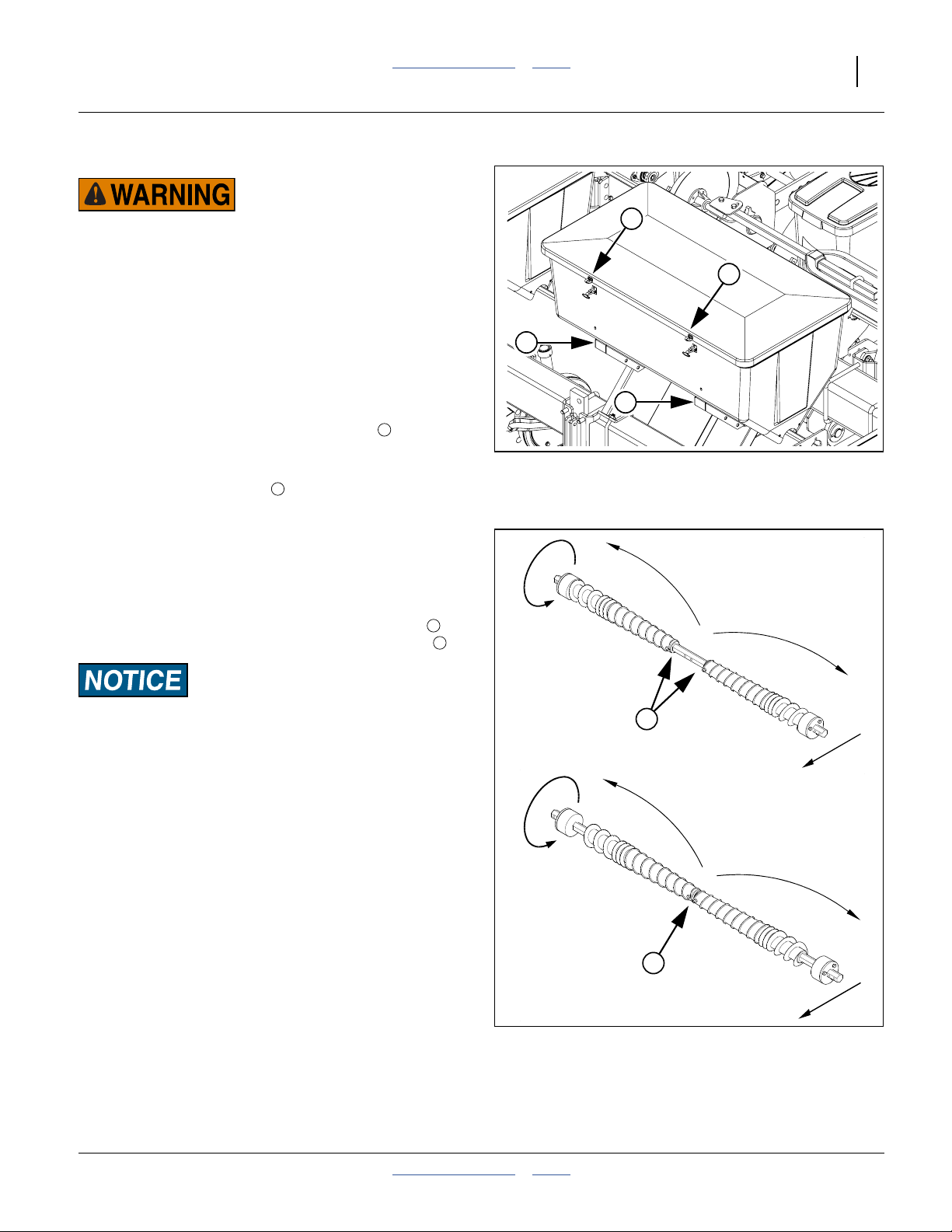
Refer to Figure 25
1. Position the planter facing into the wind, so that you
are facing downwind while loading fertilizer.
2. Check that the fertilizer hopper mounts are
re-secured from any previous hopper clean-out. See
“Fertilizer Hopper Clean-Out” on page 64.
3. Release rubber latches at hopper front. Swing lid
back until internal bungees hold it open.
4. Inspect the hopper for leftover prior materials and
debris. Clean out as necessary.
Refer to Figure 26
5. Make auger adjustment for High or Low rate. See
“Dry Fertilizer Rate” on page 37.
For low fertilizer rates, set augers as shown at .
For high fertilizer rates, set augers as shown at .
2
1
3
4
2
2
1
1
Figure 25
Fertilizer Lid Operation
28132
Loss of Time Risk:
Before adding fertilizer make sure that augers are rotating
correctly and are positioned for your desired rate range
setting.
6. Fill hoppers with fertilizer.
7. Close lids and secure both latches on each lid.
3
4
Figure 26
Fertilizer Auger Adjustment
15699
15696
2014-07-23 Table of Contents Index 401-479M
26 PD8070 Table of Contents Index Great Plains Manufacturing, Inc.
Seed Drive Clutch
Meter Clutch Disengagement
The seed meter may be disengaged from the drive
system, as required in several situations, for example:
• hopper removal for clean-out, meter exchange or
maintenance
• treatment meter calibration
• application without seeding
Refer to Figure 28
To disengage a meter, pull the knob away (left) of the
row unit. Rotate the knob until the inner cross-pin is
seated in the shallow detents of the hub.
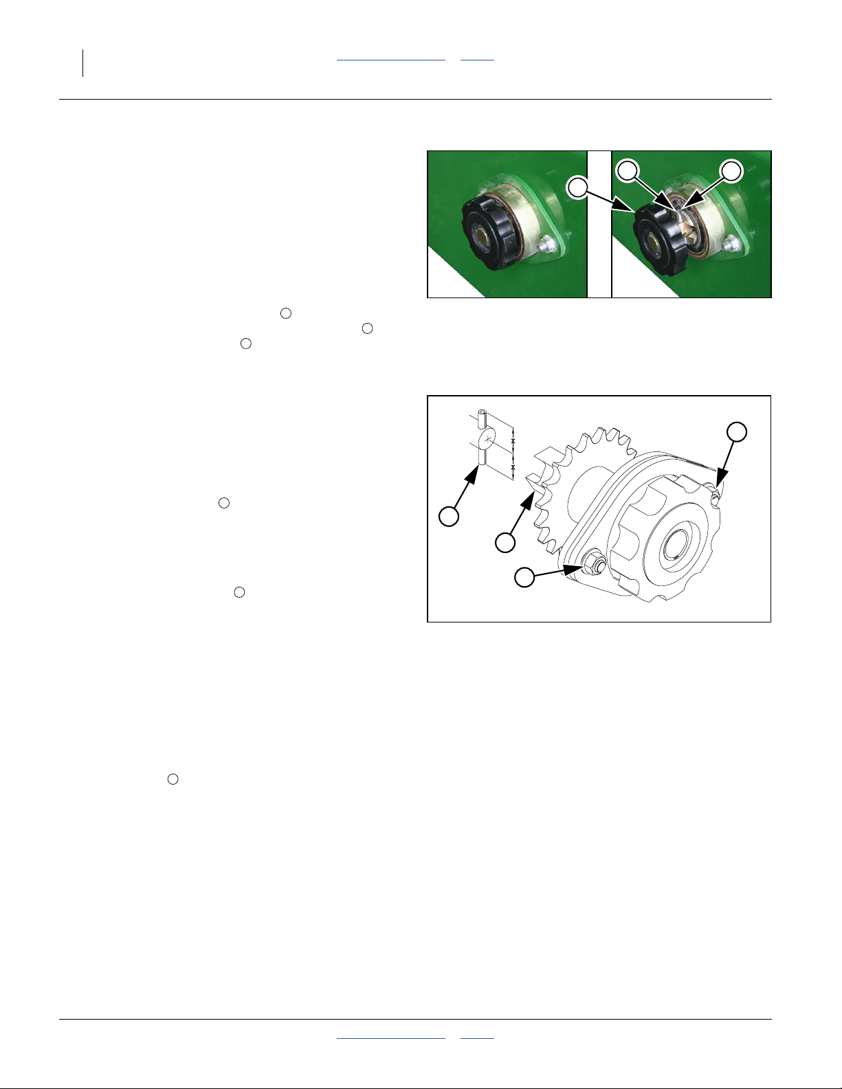
Meter Shaft Alignment
The meter clutch and meter-input shaft must be aligned.
Misalignment causes meter malfunction and excessive
meter-housing and clutch wear. Periodically check
vertical and horizontal alignment of meter clutch and
meter-input shafts.
Refer to Figure 28
1. Latch hopper onto hopper support cross-tube.
2. Check that the roll pin in the end of the meter input
shaft is centered. When centered, equal amounts of
the roll pin protrude from both sides of the shaft.
3. Rotate the meter input shaft so that the roll pin is
vertical.
4. Rotate the drive coupler on meter clutch so that
the slots are vertical.
5. Release the meter clutch to engage the meter input
shaft.
6. If shafts are aligned vertically, the drive coupler
engages with the meter input shaft freely and the roll
pin extends equally on each side of the drive coupler.
Disengage the clutch and repeat steps, checking for
horizontal alignment.
7. If the drive coupler does not freely engage the meter
input shaft vertically and horizontally, loosen the
5
⁄16inch nuts on the flangette. Engage the meter
clutch. Align the meter clutch with the meter input
shaft. Tighten the nuts5⁄16inch nuts to Grade 5
torque specification.
6
4
5
1
2
3
1
Figure 27
Seed Meter Clutch
Note: On a dual-meter planter, the seed meter drive
clutch is the forward clutch.
4
5
6
Figure 28
Seed Drive Coupler (Clutch)
2
3
34472
6
17891
401-479M Table of Contents Index 2014-07-23
 Loading...