

Page 1

ENGLISH
P18028E
JANUARY 2012
OPERATORS MANUAL
& PARTS LIST
DTX 300 / 350
Page 2

ENG If you require a copy of this document in your native language
pleasecontactyourdealerorSimbaGreatPlains.
DAN Hvisduharbrugforeteksemplarafdettedokumentpåditsprog,
bedesdukontaktedinforhandlerellerSimbaGreatPlains.
CZE Požadujete-li kopii tohoto dokumentu ve svém rodném jazyce,
obraťte se prosím na svéhoprodejcenebo na společnost Simba
GreatPlains.
HUN Haszeretnéeztaleírástmagyarulismegkapni,kérjük,értesítsea
forgalmazójátvagyaSimbaGreatPlains-t.
FRA Pourobtenirunexemplaireduprésentdocumentdanslalanguede
votrechoix,veuillezcontacter votre représentantouSimbaGreat
Plains.
LIT JeiprireiktųšiodokumentokopijosJūsųgimtąjakalba,kreipkitėsį
savoplatintojąarbaį„SimbaGreatPlains“.
BUL Аковиенеобходимокопиенатозидокументнародниявиезик,
моля да се обърнетекъм вашия дилър или към Simba Great
Plains.
RUM Dacă aveţi nevoie de o copie a acestui document în limba
dumneavoastră natală vă rugăm să vă contactaţi dealerul sau
SimbaGreatPlains.
RUS Чтобы получить копию данного документа на вашем родном
языке, обратитесь к своему дилеру или в компанию «Simba
GreatPlains»
GER WennSieeinExemplardiesesDokumentsinIhrer Muttersprache
brauchen,dannwendenSiesichbitteanIhrenHändleroderandie
SimbaGreatPlains.
Page 3

Declaration of Conformity
DECLARATION OF CONFORMITY
Simba International Limited hereby declare that the Simba DTX, as dened by the Serial Number attached
to the Machine Chassis, conforms with the following Directives and Regulations, and has been certied
accordingly.
EC Machinery Directive 2006/42/EC.
The Supply of Machinery (Safety) Regulations 2008.
The Provision and Use of Work Equipment Regulations 1998.
Specically related harmonised standards are:
EN ISO 12100-1: 2003 (Safety of Machinery).
EN ISO 12100-2: 2003 (Safety of Machinery).
EN ISO 4254-1: 2009 (Agricultural machinery - Safety - General Requirements).
THE MANUFACTURER:
Simba International Limited
Woodbridge Road
SLEAFORD
Lincolnshire
NG34 7EW
England
Telephone (+44) (0)1529 304654.
CERTIFIED ON BEHALF OF SIMBA INTERNATIONAL LIMITED:
Colin Adams
Managing Director
3DTX
Operating Instructions
Page 4

Introduction
WARRANTY
TERMS AND CONDITIONS
In this warranty Simba International Ltd., is referred to as “the Company”.
1. Subject to the provisions of this warranty the Company warrants each new machine sold by it to
be sold free from any defect in material or workmanship for a period of 12 months from date of
installation with the end-user.
Some specic items have additional warranty over and above the standard 12 months. Details of
these can be obtained upon request directly from the distributor or Simba International Ltd.
2. If the machine or part thereof supplied by the Company is not in accordance with the warranty
given in clause 1 the Company will at its option:
(a) make good the machine or part thereof at the Company’s expense, or
(b) make an allowance to the purchaser against the purchase price of the machine or part
thereof, or
(c) accept the return of the machine and at the buyers option either:
I) repay or allow the buyer the invoice price of the machine or part thereof, or
II) replace the machine or part thereof as is reasonably practical.
3. This warranty shall not oblige the Company to make any payment in respect of loss of prot or
other consequential loss or contingent liability of the Purchaser alleged to arise from any defect
in the machine or impose any liability on the Company other than that contained in clause 2.
4. Any claim under this warranty must be notied to the Company in writing specifying the matters
complained of within 14 days from the date of repair.
5. Any claim under this warranty must be made by the original purchaser of the machine and is not
assignable to any third party.
6. If the purchaser hires out the machine to any third party the warranty shall apply only to matters
notied to the Company in writing within 90 days of the date of delivery and clause 1 shall be read
as if the period of 90 days were substituted for the period of 12 months.
7. The warranty will cease to apply if:
(a) any parts not made, supplied or approved in writing by the Company are tted to the machine or
(b) any repair is carried out to the machine other than by or with the express written approval of the
Company or
(c) any alterations not expressly authorized by the Company in writing are made to the machine or
(d) the machine is damaged by accident or
(e) the machine is abused or overloaded or used for a purpose or load beyond its design capabilities,
or used in conjunction with a tractor whose power output capability exceeds the stated implement
power requirement by more than 40%. For the purpose of these terms and conditions, “stated
implement power requirement” refers to wheeled tractors unless specically stated. These power
requirements should be reduced by 20% when used in conjunction with tracked tractors.
(f) the machine is operated as part of a ‘cultivation train’ where more than one implement is being
towed, without the express written approval of Simba International Ltd.
(g) any maintenance is not carried out in accordance with the service schedules in the operator’s
manual.
(h) the Installation and Warranty Registration Certicate is not received by Simba International Ltd.,
Service Dept., Woodbridge Road, Sleaford, Lincolnshire, England, NG34 7EW, within 7 days of
installing a new machine.
DTX
4
Operating Instructions
Page 5

Machine Identication
Machine Identication
Enter the relevant data in the following list upon acceptance of the machine:
Serial Number
Type of Machine
Machine Width
Year of Construction
Delivery Date
First Operation
Accessories
Operating Instructions/Spare Parts List: January 2012
Dealer Address:
Name: _________________________________
Street: _________________________________
Place: _________________________________
Tel.: _________________________________
Dealer’s Customer No.: ______________________
Simba Great Plains Address:
Simba Great Plains
Woodbridge Road Ind. Est.
Sleaford
Lincolnshire
NG34 7EW
Tel.: +44 (0) 1529 304654
Fax: +44 (0) 1529 413468
E-Mail: simba.international@simba.co.uk
Customer No.: _________________________
Operating Instructions
5DTX
Page 6

Contents
Contents
Machine Identication .............................................................................................................5
Introduction ..............................................................................................8
Foreword ..........................................................................................................................8
Warranty Guidelines .........................................................................................................8
1. Safety Data .......................................................................................9
1.1 Safety Symbols .......................................................................................................9
1.2 Use for the Intended Purpose .............................................................................. 11
1.3 Operational Safety ................................................................................................11
1.4 No Liability for Consequential Damage................................................................. 11
1.5 Road Trafc Safety ...............................................................................................12
1.6 Accident Prevention ..............................................................................................12
1.6.1 Hitching-up the machine .......................................................................................12
1.6.2 Changing Equipment ............................................................................................12
1.6.3 During Operation...................................................................................................13
1.7 Servicing & Maintenance ......................................................................................13
2. Transportation and Installation .....................................................15
2.1 Delivery .................................................................................................................15
2.2 Transportation .......................................................................................................15
2.3 Installation .............................................................................................................15
2.4 Hitching Up / Preparing for Transport ...................................................................16
2.5 When driving on the road ......................................................................................16
2.6 Parking the machine .............................................................................................16
3. Technical Data ................................................................................17
4. Adjustment/Operation .....................................................................18
4.1 Description ............................................................................................................18
4.2 3 Point Linkage .....................................................................................................20
4.3 Tines .....................................................................................................................20
4.3.1 Pro-Lift Wings .......................................................................................................20
4.4 Disc Units ..............................................................................................................21
4.5 DD Lite Roller........................................................................................................21
4.6 DD600 Roller ........................................................................................................21
4.7 Work Settings ........................................................................................................22
4.8 General Rules When Setting the DTX ..................................................................22
4.9 Starting Settings....................................................................................................23
4.10 Adjusting Depth.....................................................................................................23
4.11 TurboJet ................................................................................................................24
4.12 Work Instructions ..................................................................................................24
4.13 Parking the machine .............................................................................................24
4.14 Checks ..................................................................................................................24
DTX
6
Operating Instructions
Page 7

Contents
5. Servicing and Maintenance ............................................................25
5.1 Servicing ...............................................................................................................25
5.2 Cleaning ................................................................................................................25
5.3 Disc Hub Maintenance .........................................................................................25
5.3.1 Tightening Disc Hubs ............................................................................................25
5.3.2 Bearing Seals........................................................................................................26
5.4 DD Lite Roll ...........................................................................................................26
5.5 DD600 Roll............................................................................................................26
5.6 Preparation for Storage.........................................................................................26
5.7 Tines .....................................................................................................................27
5.8 Operator Support ..................................................................................................27
5.9 Maintenance Intervals ...........................................................................................27
5.10 Maintenance Overview .........................................................................................28
5.11 Lubricating the Machine ........................................................................................29
5.12 Handling of Lubricants ..........................................................................................29
5.13 Lubricants .............................................................................................................30
6. Faults and Remedies ......................................................................31
7. Parts & Assembly ...........................................................................33
Operating Instructions
7DTX
Page 8

Introduction
Introduction
Foreword
Make sure you have read and follow the
Operating Instructions carefully before
using the machine. By doing so, you will
avoid accidents, reduce repair costs and
downtime and increase the reliability and
service life of your machine. Pay attention
to the safety instructions!
SIMBA will not accept any responsibility
for any damage or malfunctions resulting
from failure to comply with the Operating
Instructions.
These Operating Instructions will assist
you in getting to know your machine and in
using it correctly for its intended purposes.
First, you are given general instructions in
handling the machine. This is followed by
sections on servicing, maintenance and
the action to be taken should a malfunction
occur.
We reserve the right to alter
illustrations as well as technical
data and weights contained in
these Operating Instructions for the
purpose of improving the machine.
Warranty Guidelines
The period of liability for material defects
(warranty) relating to our products is 12
months. In the case of written deviations
from the statutory provisions, these
agreements shall apply.
They shall become effective upon
installation of the machine with the end
customer. All wear parts are excluded from
the warranty.
All warranty claims must be submitted to
SIMBA via your dealer.
These operating instructions are to be read
and followed by all persons working on or
with the machine, e.g.:
• Operation (including preparation,
remedying of faults in the operating
sequence and servicing).
• Maintenance (maintenance and
inspection)
• Transportation.
Together with the Operating Instructions,
you receive a Spare Parts List and a
Machine Registration form. Field service
technicians will instruct you in the operation
and servicing of your machine. Following
this, the Machine Registration form is to
be returned to your dealer. This conrms
your formal acceptance of the machine.
The warranty period begins on the date of
delivery.
DTX
8
Operating Instructions
Page 9

1. Safety Data
1.0 Safety Data
The following warnings and safety
instructions apply to all sections of these
Operating Instructions.
1.1 Safety Symbols on
the machine
Read and observe the
Operating Instructions
before using the machine!
Parts may y off during
operation. Keep a safe
distance away from the
machine!
Keep clear of the working
range of foldable machine
components!
Watch out for escaping
pressurised uids! Follow
the instructions in the
Operating Instructions!
Never reach into areas
where there is a danger of
being crushed by moving
parts!
No passengers are allowed
on the machine!
Never reach into any
revolving parts!
Operating Instructions
9DTX
Page 10

1. Safety Data
Refer to Operating
Instructions before
attempting maintenance.
Operating Instructions:
The Operating Instructions distinguish
between three different types of warning
and safety instructions. The following
graphic symbols are used:
Important!
Risk of injury!
Risk of fatal and serious injuries!
It is important that all the safety instructions
contained in these Operating Instructions
and all the warning signs on the machine
are read carefully.
Ensure that the warning signs are legible.
Replace any signs that are missing or
damaged.
These instructions must be followed in order
to prevent accidents. Inform other users of
the warnings and safety instructions.
Do not carry out any operations which may
affect safe use of the machine.
All references to left and right in this manual
are made from the rear of the machine,
facing the direction of travel (unless
otherwise stated).
DTX
10
Operating Instructions
Page 11

1. Safety Data
1.2 Use for the Intended
Purpose
The SIMBA DTX is built using the latest
technology and in accordance with the
relevant recognised safety regulations.
However, risks of injury for the operator or
third parties and impairment of the machine
or other tangible assets can arise during
use.
The machine is only to be operated when
in a technically perfect condition and for the
intended purpose, taking into consideration
safety and risks and following the
Operating Instructions. In particular, faults
that can impair safety are to be remedied
immediately.
Original parts and accessories from SIMBA
have been specially designed for this
machine. Spare parts and accessories not
supplied by us have not been tested or
authorised. Installation or use of non-original
SIMBA products may have a detrimental
effect on specic design features of the
machine and affect the safety of machine
operators and the machine itself. SIMBA
will accept no liability for damage resulting
from the use of non-original parts or
accessories.
1.3 Operational Safety
The machine is to be put in operation
only after instruction has been provided
by an employee of the authorised dealer
or an employee of SIMBA. The “Machine
Registration” form is to be completed and
returned to your dealer.
All protective and safety equipment, such
as removable protective equipment, must
be in place and functioning reliably before
the machine is put in use.
Check screws and bolts regularly
for tightness and retighten if
necessary.
In the event of malfunctions,
stop and secure the machine
immediately.
Ensure that any faults are
remedied immediately.
1.4 No Liability for
Consequential Damage
The DTX has been manufactured by SIMBA
with great care. However, problems may
still occur when it is used for the intended
purpose. These may include:
The SIMBA DTX is designed solely as a
cultivation implement. Use for any other
purpose, e.g., as a means of transport,
will be deemed to be improper use. SIMBA
will accept no liability for damage resulting
from improper use. The risk will be borne
solely by the operator.
Use of the DTX behind high power tractors
(in excess of 40% above the maximum
recommended) can lead to high loads
and stresses which can cause long term
structural damage to the chassis and
key components. Such overloading can
compromise safety and is to be avoided.
• Worn wearing parts.
• Damage caused by external factors.
• Incorrect driving speeds.
• Incorrect setting of the unit (incorrect
attachment, non-adherence to the Setting
instructions).
Therefore, it is crucial to
always check your machine
before and during operation for
correct operation and adequate
application accuracy.
Compensation claims for damage which
has not occurred to the machine is
excluded. This includes any consequential
damage resulting from incorrect operation.
11DTX
Operating Instructions
Page 12
1. Safety Data
1.5 Road Trafc Safety
When driving on public roads, tracks and
areas, it is important to observe the relevant
road trafc laws as well as the specic
regulations relating to this machine.
Pay attention to the permitted axle
loads, tyre carrying capacity, and
total weight in order to maintain
adequate braking and steerability.
Passengers on the machine are
strictly forbidden!
Check that lights / indicators (if
applicable) are working before
transporting the machine.
Max. road transport speed 16mph
(25km/h).
Beware of trapping hazards
when manipulating the parking
stands, steps or other moving
parts. Ensure any heavy
components are fully supported
when removing pins / bolts.
1.6.1 Hitching-up the
machine
There is a risk of injury when hitching/
unhitching the machine. Observe the
following:
• Secure the machine against rolling.
• Take special care when reversing the
tractor!
• There is a risk of being crushed between
the machine and the tractor!
• Park the machine on rm, level ground.
1.6 Accident Prevention
In addition to the Operating Instructions,
it is important to observe the accident
prevention regulations specied by
agricultural trade associations. It is the
Operator’s responsibility to ensure that all
other persons are excluded from the danger
zones surrounding or on the machine
during its operation.
It is the Owner’s responsibility to ensure:
• the Operator is trained and competent
to use the machine
• the tractor is suitable for the machine
• adequate Risk and COSHH assessments
have been undertaken regarding the
machine’s use. Specically, these
include issues concerning contact with
the soil, dust, crop residues, chemicals,
lubricants and other compounds during
operation or maintenance, and the
possibility of stones being ejected at
high speed during work.
&
tractor,
1.6.2 Changing
Equipment
• Secure the machine to prevent it from
accidentally rolling away!
• Use suitable supports to secure any
raised frame sections suspended above
you!
• Caution! Risk of injury due to projecting
parts!
Never climb on to rotating parts
such as the roll unit. These parts
may rotate causing you to slip and
suffer serious injury!
Removing components during
maintenance may affect the
stability of the machine. Ensure
it is fully supported in case of
unexpected weight shifts.
DTX
12
Operating Instructions
Page 13

1.7 Servicing &
Maintenance
Ensure that regular checks and inspections
are always carried out within the periods
required by law or specied in these
Operating Instructions.
When carrying out service and maintenance
work always:
• switch off the tractor engine and remove
the ignition key.
• wait until all the machine parts have
stopped moving.
• depressurise the hydraulic system.
Many hydraulic circuits contain lock or
overcentre valves which can retain pressure
in the lines even after depressurising the
tractor side of these circuits. If in doubt,
consult trained personnel (such as your
local Simba Dealer) to ensure such valves
are depressurised to the correct procedure
before removing or servicing any parts
connected downstream of these valves.
Check all hydraulic lines for leaks, loose
connections, chafe marks and damage.
Remedy any deciencies immediately!
Pay particular attention to hose renewal
intervals as outlined in the specic sections
which follow. ALL hydraulic hoses have a
safe maximum working life of 6 (SIX) years
from date of installation, provided they
remain in a safe condition. Hoses which
exceed 6 years of age should be replaced,
or inspected and certied by a suitably
qualied person to have an extended life
period which should be recorded.
1. Safety Data
Pay particular attention to those items which
require specialist service tools or training to
be carried out by qualied personnel. Do
not attempt to service these items yourself!
These include items retaining pressure
(e.g. accumulator circuits), or force (e.g.
spring tines), and DD axles of any type.
13DTX
Operating Instructions
Page 14

2. Transportation / Installation
DTX
14
Operating Instructions
Page 15

2. Transportation / Installation
2.0 Transportation
and Installation
Transportation and initial installation of the
machine are described in this chapter.
2.1 Delivery
The machine is normally delivered fully
assembled.
• The machine can be lifted off with a
crane or other suitable lifting equipment.
• The machine should be hitched to a
tractor and driven off a low-loader.
2.2 Transportation
The DTX can be transported on public
roads by hitching it up to a tractor or on a
low-loader.
• It is important to observe the permitted
dimensions and weights when
transporting the machine.
• If the machine is transported on a trailer
or a low-loader, it must be secured
using straps or other devices.
2.3 Installation
When carrying out installation and
maintenance work there is a higher risk of
injury. It is important that you familiarise
yourself with the machine and read the
Operating Instructions beforehand.
Operator instruction and initial installation of
the machine are carried out by our service
technicians or authorised distributors.
The machine must not be used in any way
beforehand! The machine can only be
released for operation after instructions
have been provided by our service
technicians or authorised distributors.
• If any modules or parts have been
removed for transportation, these shall
be mounted by our service technicians/
authorised dealers before the instruction
takes place.
• Check all important screw connections!
• Lubricate all nipples and joints!
• Check all hydraulic connections and
lines for damage.
• Before transporting the machine on
public roads, it must be adjusted
to its transportation position and
the stipulations relating to road
transportation fullled.
• The maximum permissible speed is
25km/h.
On machines tted with a
TurboJet seeder unit the hopper
should be emptied before road
transport.
Operating Instructions
15DTX
Page 16
2. Transportation / Installation
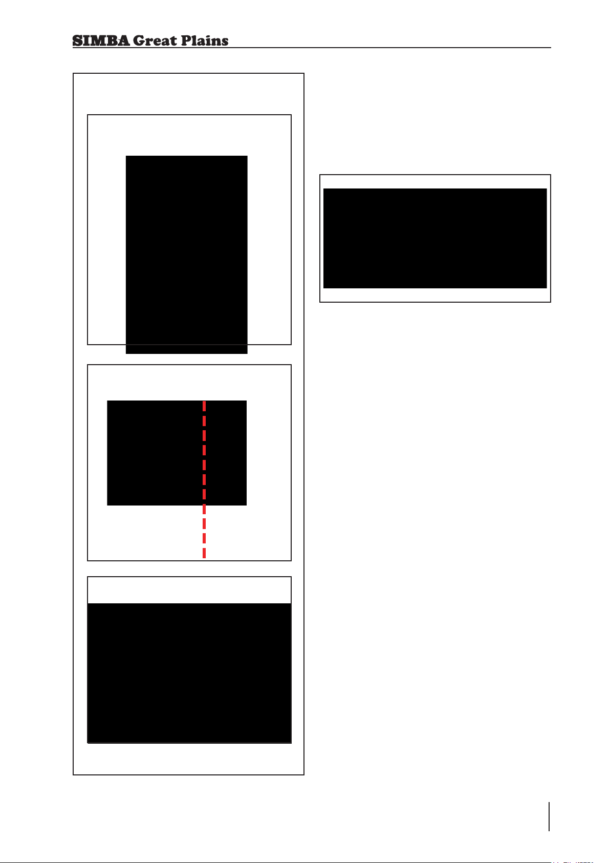
2.4 Hitching Up / Preparing
for Transport
When hitching-up the machine,
ensure that no-one is between
the tractor and the machine.
1. Connect the tractor to the machine
using the hydraulics to raise or lower
the the height of the tractor lower link
arms.
2. When the lower link arms are aligned
t the lower link pins and the lynch
pins.
3. Fit the tractor toplink between the
tractor and the machine.
4. Raise the machine using the tractor
link arms.
2.6 Parking the machine
In order to avoid damage as a result of
moisture, the machine should be parked, if
possible, indoors or under cover.
When manoeuvring the
machine, pay attention to your
surroundings. Ensure that
nobody is in the manoeuvring
area (watch for children!).
Park the machine on level and solid
ground.
Lower the machine onto the parking
stands / tines ensuring that it is stable.
Remove the toplink and lower the link
arms so that pins can be removed.
Switch off the tractor.
2.5 When driving on the
road
When driving on the road the machine must
be converted to the transportation position.
When driving on the road, raise
the machine completely to
prevent the working elements
dragging on the ground.
Ensure that the tractor rear lights
are visible from behind during
transport.
Fig. 2A: Parking Position
DTX
16
Operating Instructions
Fig. 2B: Parking Stand Stowage
Page 17

3. Technical Data
3.0 Technical Data
3.0m 3.5m
Working Width 3000mm 3500mm
Transport Width 3000mm 3500mm
Transport Height N/A N/A
Transport Length 3356mm 3356mm
Weight 2590kg 3260kg
Centre of Gravity* 1642mm 1620mm
Tractor Power Req.** 200-300Hp 200-400Hp
* Dimension from linkage in transport position.
** It is important to correctly match your implement to your tractor for optimum performance.
Operating Instructions
17DTX
Page 18
4. Adjustment / Operation
4.0 Adjustment/Operation
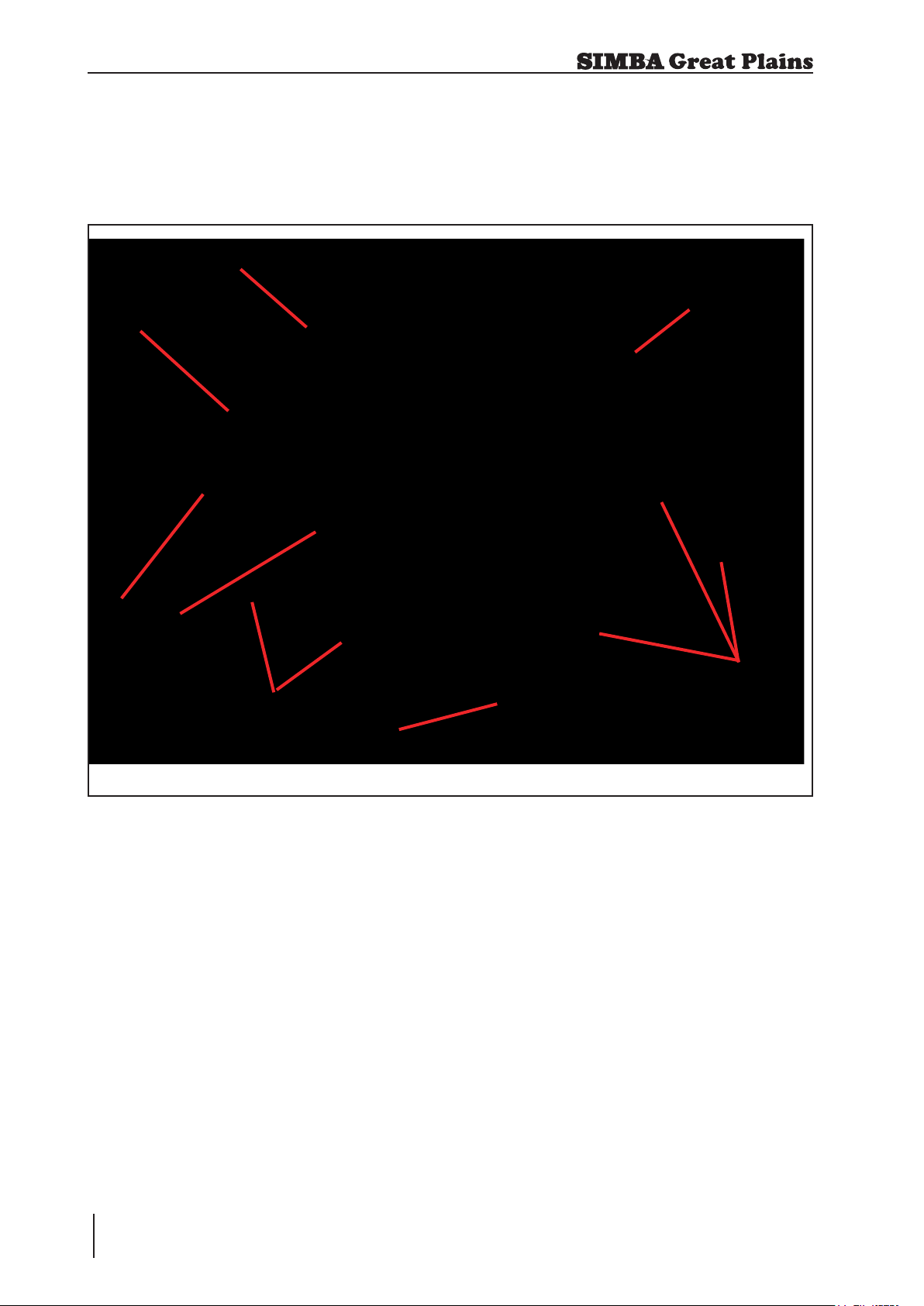
4.1 Description
7
6
4
5
4
3
Fig. 4.01: Simba DTX 300
1. 3 Point Linkage
2. Pro-Lift Tines
3. Discs
4. Disc Angle Adjuster
5. Roll Depth Linkage
6. DD Lite Roll
7. DD Lite Scrapers
1
2
DTX
18
Operating Instructions
Page 19

The SIMBA DTX is an amalgamation of
time proven, successful Simba designed
components brought together to form this
important development. The DTX provides
a one pass mix with a ssured layer at disc
depth for through drainage and root access
to lower horizons. This enables rapid
drainage and access after rain, creating
a greater effective capacity for moisture
compared to ploughing for the same
effective total depth of cultivation.
In principle, the machine is a subsoiler
followed by an offset disc designed for
low draft, high speed operations. The
addition of a rear mounted roll enables
effective cultivation in one pass. The key
to the DTX’s success are the tines which
maintain shatter across the full width of
cultivation. This is followed by the discs
that cultivate the soil surface and minimise
and clod formation. Finally, the rear roll
consolidates the surface, cracks any clods
and rms the soil prole after the rear discs
complete mixing to depth. This starts the
‘top down’ cultivation process, retaining
weathered tilth in the surface level for stale
seedbed purposes. The corrugated top
and shattered lower horizons are left fully
weatherproof to any conditions between
cultivation and drilling whilst retaining
moisture below the surface for rapid straw
breakdown and optimum establishment of
the next crop.
4. Adjustment / Operation
Operating Instructions
19DTX
Page 20
4. Adjustment / Operation
4.2 3 Point Linkage
The DTX 300 is tted with a standard
Category 3 linkage at the front of the
machine.
Fig. 4.02: 3 Point Linkage
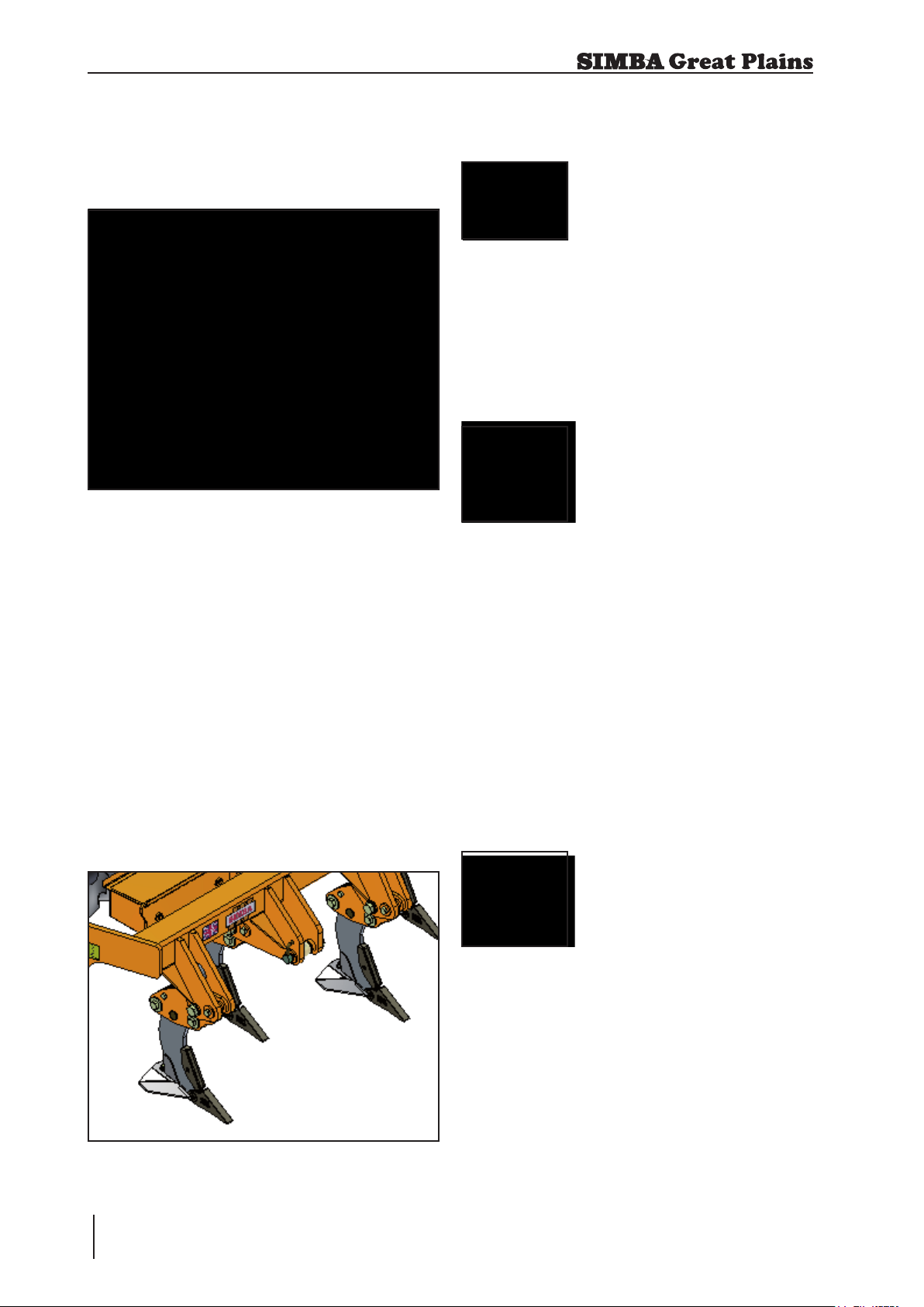
4.3 Tines
The DTX is tted with either Pro-Lift or
LD (Low Disturbance) tines. The tines are
arranged in a staggered formation to give
lower draft requirements and the ability to
work progressively deeper. The tines are
spaced at 400mm. Each tine is shear bolt
protected. Tine depth is achieved by moving
the tines up and down in the adjustable
clamps.
Different wings are available to suit the soil
conditions and optimise the performance
of the machine.
4.3.1 Pro-Lift Wings
Standard Wing
P09060
Maximum soil disturbance with
minimum draft requirement under
normal circumstances.
Wing angle reduces wear rates on
leg.
Extra Lift Wing
P10392
Increased lift height and rake angle
creates greater soil disturbance on
all soil types especially in moister
conditions.
Lower relative distance between
edge of wing and point reduces draft
requirement.
Has ability to work at lower depths
with no decrease in soil disturbance
or risk of smear.
Fig. 4.03: Pro-Lift Tines
DTX
20
Operating Instructions
Extra Wide Wing
P10411
Improved lateral shatter in moist/wet
soils, or non-cohesive soils.
Ideal for deep vegetable applications
under light/medium soils.
Page 21

4. Adjustment / Operation
4.4 Disc Units
The DTX features two rows of discs which
chop and mix the crop residue. A disc
spacing of 250mm ensures a ne tilth.
The discs tted to the DTX are 500mm in
diameter (20”) and 6mm thick. They are
manufactured from heat treated chrome
boron steel which ensures excellent wear
resistance and enhanced working life.
Each disc is mounted on a Pro-Active
sprung leaf linked to a track rod system.
Gang angles can be varied with ease and
accuracy using a graduated adjuster.
Adjustable angling of the discs (between
10°-25°) ensures penetration and stubble
mixing are achieved in one pass. Working
depth can be varied via the 3 point linkage
and the rear roll linkage.
4.5 DD Lite Roller
The DD Lite roller is made up of individual
Double Disc (patented) Ring segments.
The DD Lite roll is designed to consolidate
the soil whilst cutting and crushing any
clods.
Even in heavy, wet soils it can easily be
operated with minimal blockages occurring.
The rear DD Lite roller carries a proportion
of the machine’s weight to ensure
consolidation. It also regulates the depth
of the disc units. The corrugated surface
left by the roller is weatherproof both for
wet or dry situations.
A level, evenly cultivated nish is maintained
by adjusting the balance of soil throw
between the front and rear disc.
Sprung Pro-Active leaves offer protection
against damage as well as offering a
degree of contour following as they ex up
and down in work.
Fig. 4.05: DD Lite Roller
4.6 DD600 Roller
The standard DD600 roller is made up of
individual Double Disc (patented) Ring
segments.
The DD rings are designed to consolidate
the soil whilst cutting and crushing any clods.
Even in heavy, wet soils it can easily be
operated with minimal blockages occurring.
Fig. 4.04: Discs
The rear DD Lite roller carries a proportion
of the machine’s weight to ensure
consolidation. It also regulates the depth
of the disc units. The corrugated surface
left by the roller is weatherproof both for
wet or dry situations.
21DTX
Operating Instructions
Page 22

4. Adjustment / Operation
4.7 Work Settings
Optimum performance has been found to
be achieved when the DD roll rings have
worn away the painted nish leaving a
smooth shiny surface. When the DD rings
are new or rusty, soil may tend to pick up on
the surface and blockage may occur, this
will reduce when the rings are shiny again.
The DTX should be run with the chassis level
to slightly tail low. In practice it is possible
to use the DTX on ground conditions that
are unsuitable to achieve the desired
effect, and it is usually possible to operate
the DD roll without regular blockage under
such unsuitable conditions, assuming that
the roll assemblies are tight, the scrapers
correctly adjusted and rings smooth. As
such, especially under wet conditions, it is
advisable to check on the cultivation effect
of the DTX.
4.8 General Rules when
Setting the DTX
The lighter the land conditions the
less the disc angle required and the
forward speed can be increased.
The wetter the land conditions the less
the disc angle required and the forward
speed will need to be decreased.
Heavier land will require more of a disc
angle and a slower forward speed.
The more the trash the less the angle
on the discs and forward speed will
have to be decreased.
On ploughed land reduce the disc
angle to give a cutting/chopping
action.
The DTX should be lifted fully clear of the
ground for all headland turns. Turning with
the tines, disc units or roller on the ground
could lead to damage of these components.
In work, the tractor lower link arms
should be run in position control with draft
introduced if required.
In hard conditions increase the disc
angle to increase penetration.
DTX
22
Operating Instructions
Page 23
4. Adjustment / Operation
4.9 Starting Settings
Tine Depth
.
Disc Angle
4.10 Adjusting Depth
To change the working depth it is advisable
to lift the machine clear of the ground so
that the rear roll linkage becomes loose.
Move the position of the depth pins to
change the depth.
Fig. 4.06: Roll Linkage
When the depth has been altered, lower the
machine into work and check operation. If
the depth change has been signicant then
other setting could be affected. This could
be chassis pitch (front to rear) and disc
angle for the given depth.
Roll Depth
.
A small amount of cultivation, eg. a 20
metre run, should be carried out before
altering these settings to check whether
they are now suitable for the cultivation
effect required. These settings should be
addressed immediately to prevent too
much work being carried out.
SPRUNG LEAF
.
Operating Instructions
23DTX
Page 24

4. Adjustment / Operation
4.11 TurboJet
The SL can be tted with an optional
TurboJet Oil Seed Rape applicator. The
Turbo Jet is an air seeder unit which uses
two fans to deliver seed behind the rear roll
in work.
The TurboJet can be operated from the cab
of the tractor using an advanced computer
control module, the RDS Wizard System.
Fig. 4.07: DTX with TurboJet
4.13 Parking the machine
In order to avoid damage as a result of
moisture, the machine should be parked, if
possible, indoors or under cover.
When manoeuvring the
machine, pay attention to your
surroundings. Ensure that
nobody is in the manoeuvring
area (watch for children!).
Park the machine on level and solid
ground.
Lower the machine onto the parking
stands / tines ensuring that it is stable.
Remove the toplink and lower the link
arms so that pins can be removed.
Switch off the tractor.
4.14 Checks
The working quality depends on the
adjustments and checks made prior to and
during work, as well as on regular servicing
and maintenance of the machine.
4.12 Work Instructions
Driving speed
The DTX 300 can be driven at speeds of up
to 12 km/h.
This depends on the eld conditions (type
of soil, surface trash, etc.).
Drive more slowly if the conditions are
difcult or a rmer nish is required.
Turning:
Before turning, the machine should
be lifted out of work while driving.
Likewise, it should lowered back
into work once the turn has been
completed.
Before beginning work it is therefore
important to carry out any necessary
servicing and to lubricate the machine as
required.
Checks prior to, and during
work:
Is the machine correctly hitched up
and the coupling device locked?
Is the machine in a level operating
position and the working depth set
correctly?
Working Elements
Are the discs and other cultivation
tools in a serviceable condition?
Are the scrapers still operable, so that
the rolls do not jam?
DTX
24
Operating Instructions
Page 25
5. Servicing and Maintenance
5.0 Servicing and
Maintenance
Follow the safety instructions for
servicing and maintenance.
5.1 Servicing
Your machine has been designed and
constructed for maximum performance,
operational efciency and operator
friendliness under a wide variety of
operating conditions.
Prior to delivery, your machine has
been checked at the factory and by your
authorised dealer to ensure that you
receive a machine in optimum condition.
To ensure trouble-free operation,
it is important that servicing and
maintenance work is performed at
the recommended intervals.
Regularly examine hub caps,
seals, shear and pivot bolts and
all tracking bolts for tightness
and effectiveness twice weekly
or every 50 working hours
(whichever is more frequent).
5.3.1 Tightening Disc Hubs
1 Ensure that the bearing seal is in the
correct orientation when replacing /
assembling components.
2 Ensure that the stub axle is free from
dirt and the nut and outer bearing can
easily slide on it.
3 Tighten the crown nut with a hand
spanner (a torque wrench is not
req uired) while turning th e hub
clockwise until the bearing drags
slightly (you feel the hub turning
heavily). Some resistance will be due
to friction from the seal.
5.2 Cleaning
In order to ensure that the machine is
always in operating condition and to
achieve optimum performance, perform
the cleaning and servicing work at regular
intervals.
Avoid cleaning the roll / disc bearings with
a high- pressure hose or a direct water jet.
The housing, screwed connections and
ball bearings are not watertight.
5.3 Disc Hub Maintenance
Grease every disc hub until
grease shows from the seals
according to the lubricating
intervals outlined on page 28.
Check disc hubs regularly for
tightness.
4 Turn back the crown nut to the next
locking position. Even if the tightening
of the nut has reached an exact xing
position, turn it back.
5 Insert the retaining pin.
6 Try to shake/rock the outer edge of the
hub/spindle: play of 0.1 / 0.2mm will
not reduce the bearings’ life and, in
addition, prevents overheating. If the
adjustment is correct the hub should
turn freely with the only friction being
from the seal.
Å
Å
Å
Å
Fig. 5.01: Checking Disc Bearing Adjustment
Operating Instructions
25DTX
Page 26
5. Servicing and Maintenance
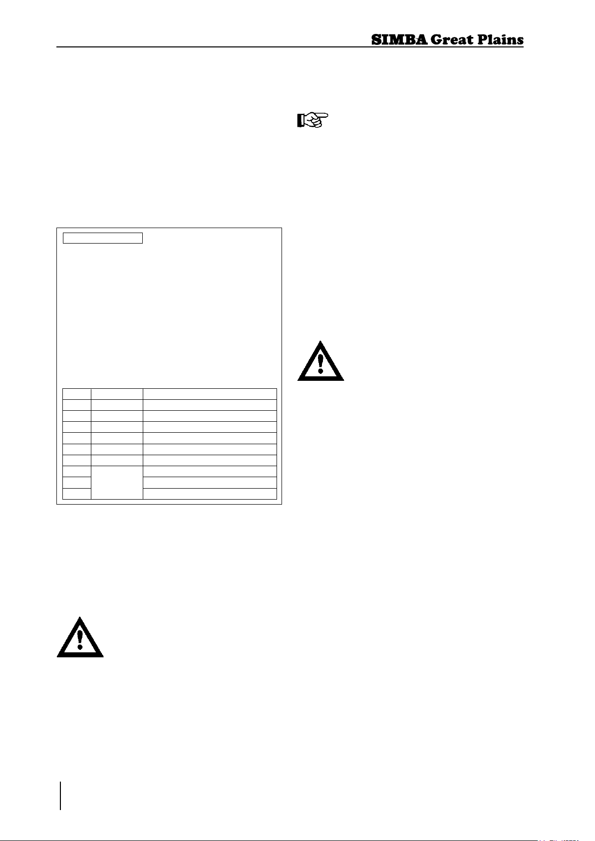
5.4.1 Bearing Seals
It is important when replacing the labyrinth
type bearing seals in disc hubs that the
seal is tted the right way round. The
chamfered lip side should be at the outside
of the bearing housing, nearest the disc
arm (see Fig. 5.02). This chamfered lip
prevents dirt ingress into the housing and
also allows grease to be ushed though
when greasing.
Chamfered Seal
ITEM PART NO DESCRIPTION
1 --- DISC ARM
2 P12900 NIPPLE - GREASE M8
3 P14593 HUB CASTING
4 P14594 HUB CAP
5 P12908 SPRING PIN
6 P12907 NUT CASTLE M27x1.5
7 SEAL 64x45x9.5
8 P12415 BEARING 32008 40x68x19
9 BEARING 32206 30x62x21
Fig. 5.02: Correct Seal Orientation
5.4 DD Lite Roll
The spacers and rings on the DD Lite Roll
are held under tension by the end plates at
the outer ends of the roll tube.
Specialist equipment is required
for the disassembly of DD Lite
rollers. Please consult your
dealer under any circumstances
that require disassembly of these
rollers.
Maintenance of these rollers is limited
to yearly/end of season greasing of the
bearings and regular inspection to ensure
the assemblies are tight, and scrapers are
correctly set.
The scraper is intended to clear
dirt from blocking between
adjacent DD rings. If adjustment
to the scrapers is required ensure
that the scraper cannot contact the
spacer even under load. Regularly
inspect the spacers for signs of
wear and adjust any scrapers to
ensure no contact can be made.
5.5 Double Disc Axles
The axles on this roller are tensioned by the
main axle through the centre of the rings
and bearings.
Specialist equipment is required
for the disassembly of Double
Disc axles. Please consult your
dealer under any circumstances
that require disassembly of these
axles.
Maintenance of these rollers is limited to
daily greasing of the bearings to ush out
dirt, and regular inspection to ensure the
assemblies are tight, and scrapers are
correctly set. The axles can be tightened
provided the bearing pillar ‘U’ bolts are
loosened to avoid preloading the bearings
as they move sideways to each other.
Ensure the bearing pillars are re- tightened
to the mainframe after this.
5.6 Preparation for
Storage
If you need to store the machine for a longer
period, observe the following points:
• Park the machine undercover if possible.
• Protect the roll / discs against rust. If you
need to spray the implements with oil, use
light, biologically degradable oils, e.g. rape
oil.
DTX
26
Operating Instructions
Page 27

5. Servicing and Maintenance
Cover any rubber sections before
using oil sprays. These sections
must not be oiled. Remove
any traces of oil with a suitable
cleaning agent.
5.7 Tines
When performing maintenance
work on tines extreme care
should be taken. Wear goggles
and gloves at at all times when
maintaining tines.
Safely support unfolded machine
in raised position using taps
and stands before attempting
maintenance work on tines.
Do not attempt to assist tting
tine points with a steel headed
hammer, this can lead to
splintering of the metal due to its
hardness, which can cause injury.
If tine tting requires assistance,
a copper/hide or plastic mallet
should be used.
5.8 Operator Support
If you have a problem, please contact your
dealer. They will endeavour to solve any
problems which may occur and provide you
with support at all times.
5.9 Maintenance
Intervals
Apart from daily maintenance, the
maintenance intervals are based on the
number of operating hours and time data.
Keep a record of your operating hours to
ensure that the specied maintenance
intervals are adhered to as closely as
possible.
Never use a machine that is due for
maintenance. Ensure that all deciencies
found during regular checks are remedied
immediately.
Avoid sharp-edged and pointed
parts (disc blades, etc.) when
working on the machine.
Place the machine on suitable
supports when working
underneath! Do not work under a
machine which is not supported!
On a new machine tighten all nuts and bolts
after 5 hours work and again after 15 hours.
This also applies to parts that have been
moved or replaced. After the initial 15 hours
of work a once a week check should be
sufcient depending on daily work rates.
In order to enable your dealer to deal with
problems as quickly as possible, it helps
if you can provide them with the following
data. Always state the:
• Customer Number
• Name and Address
• Machine Model
• Serial Number of Machine
• Date of Purchase and Operating Hours
• Type of Problem
27DTX
Operating Instructions
Page 28

5. Servicing and Maintenance
5.10 Maintenance Overview
Key
Inspect
L
Grease
Settings
10 Hours
Scrapers
10 Hours
DD Lite Roll
Bearings
200 Hours
One pump only!
L
L
Disc Angle
Adjusters
200 Hours
DD600 Roll
Bearings
Parking
Stands
Linkage
Before Each Use
Tines
Before Each Use
Disc Hubs
200 Hours
See section 5.11 on page 31
L
L
DTX
28
Operating Instructions
10 Hours
Before Each Use
L
Page 29

5. Servicing and Maintenance
5.11 Lubricating the
Machine
Please read the section entitled “Using
Lubricants” carefully before lubricating the
machine.
The machine must be lubricated regularly in
order for it to remain serviceable. Regular
lubrication also contributes towards
extending the service life of your machine.
The recommended lubricating intervals are
specied in “Inspection” and “Maintenance
Intervals”.
After it has been washed using a highpressure hose or steam cleaned, the
machine should always be lubricated using
a grease gun.
5.12 Handling of
Lubricants
Please ensure that you read the following
instructions as well as the relevant
information. This also applies to any of your
employees who handle lubricants.
Hygiene
Lubricants do not present a health hazard
provided they are used for their specied
purpose.
In the case of prolonged skin contact,
lubricants - especially low-viscosity oils
- may remove the natural layer of fat
contained in the skin, resulting in dryness
and possible irritation .
It is important to take extreme care when
handling waste oil as it may contain other
irritants.
Vapours given off by cleaning agents and
oils are also a potential health hazard.
You should therefore not carry any oily
cloths around. Change soiled work clothing
as soon as possible.
Always exercise extreme care and observe
the recommended hygiene rules when
handling mineral oil products. Details of
these handling regulations can be found
in information provided by the health
authorities.
Storage and Handling
• Always store lubricants where they cannot
be accessed by children.
• Never store lubricants in open or
unlabelled containers.
Fresh Oil
• Apart from taking the usual care and
observing hygiene rules, there is no need
to take any special precautions when
handling fresh oil.
Waste Oil
• Waste oil can contain harmful contaminants
which may cause skin cancer, allergies and
other illnesses.
Attention!
Oil is a toxic substance. Should you swallow
any oil, do not try to vomit. Contact a doctor
immediately.
Protect your hands with barrier cream or
wear gloves to avoid contact with the skin.
Wash off any traces of oil thoroughly with
soap and hot water.
• Wash your skin thoroughly with soap and
water.
• Use special cleaning agents to clean any
dirt off your hands.
• Never wash oil residue from your skin with
petrol, diesel fuel or parafn.
• Avoid skin contact with any oily clothing.
• Do not keep any oily rags in your pockets.
• Wash soiled clothing before wearing it
again.
• Ensure that any oily footwear is disposed
of in the proper manner.
Operating Instructions
29DTX
Page 30

5. Servicing and Maintenance
Measures in case of injury
through oil
Eyes:
Should any oil be splashed into your eyes,
rinse with water for 15 minutes. If the eye is
still irritated, contact a doctor immediately
If oil is swallowed
If oil is swallowed, it is important not to induce
vomiting. Contact a doctor immediately.
Skin irritation caused by oil
In case of prolonged skin contact, wash off
the oil with soap and water.
Oil Spills
Use either sand or a suitable granular
absorbent to soak up any spilt oil. Dispose
of the oil-contaminated absorbent in the
proper manner.
Oil Fires
Never use water to extinguish an oil re.
The oil will oat on the water causing the
re to spread.
Burning oil-lubricant must be extinguished
using a carbon dioxide powder or foam
extinguisher. Always wear respiratory
equipment when dealing with res of this
type.
5.13 Lubricants
Simba strongly recommend the use of
Lithium Complex EP2 Grease in the disc
hubs of your DTX. This grease is a Lithium
Complex soap dispersed in a mineral
oil and is interpreted by IARC as being
non-carcinogenic. Grease cartridges are
available from Simba (P12710). Using this
grease in combination with the labyrinth type
seal it is permissible to lengthen the greasing
interval on the disc hubs to 200 hours. If
using a standard agricultural grease the disc
hubs should be lubricated every 50 hours.
Advantages of Lithium Complex EP2
Grease
Excellent mechanical stability.
Excellent load carrying properties.
Wide temperature range.
Excellent oxidation stability.
Excellent water resistance.
Compatibility with other greases.
All other lubricating points on the machine
can be lubricated with multigrade lubricating
grease as specied in DIN 51825 KP/2K -
40.
Waste Oil Disposal
Oil-contaminated waste and used oil must
be disposed of in accordance with current
legislation.
Waste oil must be collected and disposed
of in accordance with local regulations.
Never pour used oil into unsealed sewage
systems or drains or onto the ground.
DTX
30
Operating Instructions
Page 31

6. Faults and Remedies
6. Faults and Remedies
DTX Troubleshooting
Fault Possible Cause Remedy
Machine ‘bouncing’ in work. Disc angle too great. Reduce disc angle.
Speed too fast. Reduce speed (<12kmh).
DD Lite Roll blocks
regularly.
Scrapers incorrectly
adjusted
Conditions may not be
ideal for using machine.
Inadequate consolidation. Not enough weight on rear
roll.
Not enough cultivated soil
depth.
Speed too fast. Reduce speed (<12kmh).
Surface nish is uneven
Not enough roll pressure Reduce draft control
and cloddy
Wings too aggressive Fit different wings, either
Running nose down Level frame
Adjust scrapers to clear dirt
from between DD Rings.
Wait for more favourable
conditions.
Increase chassis pitch
slightly via tractor toplink.
Increase working depth.
narrower wings or wings
with a shallower rake (see
page 20)
All ground not being moved
by tines
Working too shallow Increase tine depth
Working too shallow Increase tine depth
Wings not aggressive
Fit wider wings
enough
Operating Instructions
31DTX
Page 32

7. Parts and Assembly
DTX
32
Operating Instructions
Page 33

7. Parts & Assembly
Table of contents
DTX 300 Complete Machine Assembly ... 34
DTX 350 Complete Machine Assembly ... 36
DTX 300 Mainframe Assembly ................ 38
DTX 350 Mainframe Assembly ................ 40
Toolbox Assembly .................................... 42
Pro-Lift Tine Assembly (Retrot to 2009 Model)... 44
Pro-Lift Tine Assembly (2010 Model) .............. 46
LD Tine Assembly (2010 Model) ..................... 48
DTX 300 DD Lite Roll Assembly .............. 50
DTX 350 DD Lite Roll Assembly .............. 52
DD Lite Scraper Assembly....................... 54
DTX 300 Aqueel 2 Assembly ................... 56
DTX 300 DD600 Roll Assembly............... 58
DTX 350 DD600 Roll Assembly............... 60
DD600 Axle Assembly - 6 Rings .............. 62
DD600 Axle Assembly - 7 Rings .............. 64
DD600 Axle Assembly - 8 Rings .............. 66
DD600 Pillar Assembly ............................ 68
DTX 350 Front Light Assembly ................ 70
DTX 350 Rear Light Assembly ................ 72
Sticker Guide ........................................... 74
DTX 300 Sticker Layout........................... 76
DTX 350 Sticker Layout........................... 78
TurboJet Mounting Assembly ..................80
Distributor Head Assembly ...................... 82
Radar Mounting (Aqueel 2) ..................... 84
7. Parts and Assembly
Operating Instructions
33DTX
Page 34

7. Parts and Assembly
TITLE COMPANYMASS KgCOSTCATEGORYCOMMENTSQTYMATERIALDESCRIPTIONISSUEPART NOITEM 18.54 1 TOOL BOX ASSEMBLY AAS36031 0.05 P167151 DTX 300 - STICKER KIT LAYOUTEAS36252 48.05 5 DTX TINE POCKETBAS37783 1809.48 1 DTX300 MAIN FRAME ASSEMBLYCAS38214 703.86 1 DTX300 - ROLL ASSEMBLYAAS42135 0.29 B 1ABS PlasticMANUAL - DTX 2011AP180286
C
ISSUE
6
ASSEMBLY
AS3820
FROM SERIAL NO. TO SERIAL NO.
PART NO.
AGD
20/10/2008
DATE:-
DRAWN:-
© 2009
1
2
4
3
SIMBA
DTX
MACHINE:-
DTX
34
Operating Instructions
5
DESCRIPTION:-
DTX300 - FULL MACHINE ASSEMBLY
Page 35

7. Parts and Assembly
AS3820
ITEM PART NO DESCRIPTION QTY COMMENTS
1
2
3
4
5
6
7
8
9
10
11
12
13
14
15
16
17
18
19
20
21
22
23
24
25
26
27
28
29
30
31
32
33
34
35
36
37
38
39
40
41
42
43
44
45
46
47
48
49
50
AS3603 TOOL BOX ASSEMBLY 1
AS3625 DTX 300 - STICKER KIT LAYOUT 1
AS3778 DTX TINE POCKET 5
AS3821 DTX300 MAIN FRAME ASSEMBLY 1
AS4213 DTX300 - ROLL ASSEMBLY 1
P18028 MANUAL - DTX 2011 1
DTX300 - FULL MACHINE ASSEMBLY
Operating Instructions
35DTX
Page 36

7. Parts and Assembly
TITLE
COMPANYMASS KgCOSTCATEGORYCOMMENTSQTYMATERIALDESCRIPTIONISSUEPART NOITEM
48.04 6 DTX TINE POCKETBAS37781
2136.57 A 1 DTX 350 CHASSIS ASSEMBLYAAS42502
801.56 A 1 DTX350 ROLL ASSEMBLYAAS42513
0.03 AP184841 DTX350 STICKER KIT LAYOUTAAS42524
16.00 A 1 REAR LIGHT KIT ASSEMBLYAAS44935
15.11 A 1 REAR LIGHT KIT ASSEMBLYAAS44946
0.29 B 1ABS PlasticMANUAL - DTX 2011AP180287
AAS4249
ISSUE
6
7
ASSEMBLY
2
1
FROM SERIAL NO. TO SERIAL NO.
PART NO.
KSL
23/12/2010
DATE:-
DRAWN:-
© 2009
SIMBA
4
DTX 350
MACHINE:-
3
5
DESCRIPTION:-
DTX 350 TOP LEVEL ASSEMBLY
DTX
36
Operating Instructions
Page 37

7. Parts and Assembly
AS4249
ITEM PART NO DESCRIPTION QTY COMMENTS
1
2
3
4
5
6
7
8
9
10
11
12
13
14
15
16
17
18
19
20
21
22
23
24
25
26
27
28
29
30
31
32
33
34
35
36
37
38
39
40
41
42
43
44
45
46
47
48
49
50
AS3778 DTX TINE POCKET 6
AS4250 DTX 350 CHASSIS ASSEMBLY 1
AS4251 DTX350 ROLL ASSEMBLY 1
AS4252 DTX350 STICKER KIT LAYOUT 1
AS4493 REAR LIGHT KIT ASSEMBLY 1
AS4494 REAR LIGHT KIT ASSEMBLY 1
P18028 MANUAL - DTX 2011 1
DTX 350 TOP LEVEL ASSEMBLY
Operating Instructions
37DTX
Page 38

7. Parts and Assembly
A
7
43
2
15
C
ISSUE
51
17
18
16
23
24
49
20
19
47
4
8
17
48
40
ASSEMBLY
AS3821
TO SERIAL NO.
FROM SERIAL NO.
PART NO.
2
22
13
46
8
11
7
50
AGD
02/11/2009
DATE:-
DRAWN:-
© 2008
A
5
3
45
E
44
12
37
6
33
32
35
29
27
28
9
31
1
25
41
D
SIMBA
DTX
MACHINE:-
38
26
E
DTX
38
Operating Instructions
26
14
34
5
7
36
39
21
10
30
13
41
38
38
D
42
DESCRIPTION:-
DTX300 MAIN FRAME ASSEMBLY
Page 39

7. Parts and Assembly
Y
AS3821
ITEM PART NO DESCRIPTION QTY COMMENTS
1
2
3
4
5
6
7
8
9
10
11
12
13
14
15
16
17
18
19
20
21
22
23
24
25
26
27
28
29
30
31
32
33
34
35
36
37
38
39
40
41
42
43
44
45
46
47
48
49
50
51
P00040 BOLT M36x140 GR. 8.8 2
P00407 BOLT M20x80 GR. 8.8 4
P01071 PIN Ø25x130 4
P01287 BOLT M20x150 GR. 8.8 5
P01704 BOLT M16x50 GR8.8 2
P01901 BOLT M16x80 GR. 8.8 44
P02008 NUT LOCK M16 'TYPE T' 92
P02009 NUT LOCK M20 9
P02012 NUT LOCK M36 2
P02037 WASHER SPRING M12 110
P02318 BOLT M16x120 GR. 8.8 4
P02483 LYNCH PIN CAT 1 2
P02484 LYNCH PIN CAT 2 6
P02602 WASHER FLAT M16 154
P02603 WASHER FLAT M20 8
P02789 BOLT M8x20 GR. 8.8 2
P04423 LYNCH PIN CAT 3 3
P05122 SERIAL PLATE 1
P05400 WASHER FLAT M6 3
P05401 WASHER SPRING M6 3
P07229 NUT LOCK M12 FINE 1.5 66
P07545 PLASTIC END CAP 60x60 2
P08817 WASHER SPRING M8 2
P10293 BOLT M6x20 GR. 8.8 3
P11462 DISC BLADE Ø515x6 22
P11494 BOLT M16x55 GR. 8.8 42
P12620 TOP PLATE 22
P12621 SPACER Ø36xØ16.5x31mm 44
P12622 TRACK ARM 20
P12646 PIN Ø20x125 2
P12782 SPRUNG LEAF 20mm 22
P12783 LYNCH PIN CAT 0 22
P12810 NUT CASTLE M24 22
P12815 BOLT M24x185 STRUCTURAL GR 8.8 22
P12886 Ø24xØ16x13mm SPACER BUSH 22
P13174 BOLT M12x50 GR10.9 1.5P 66
P14027 PIN Ø25x118 HANDLED 2
P14600 DISC ARM UNIT RH 11
P14601 DISC ARM UNIT LH 11
P14754 BALL CAT 3 LOWER Ø37 2
P15438 ANGLE GUIDE 2
P15926 BOLT M12x20 GR8.8x1.25 110
P16354 HOOK TRACK ROD ARM 2
P16759 TRACK ROD-11 HOLE 2
P16764 PARKING STAND 2
P17076 ADJUSTER 350-600 2
P17286 CHASSIS-DTX300 1
P17308 SHEAR BOLT STOWAGE M20 1
P17815 MANUAL HOLDER - COMPLETE 1
P17892 PIN LOWER LINK CAT 3 2
P17893 PIN UPPER LINK CAT 3 1
DTX300 MAIN FRAME ASSEMBL
39DTX
Operating Instructions
Page 40

7. Parts and Assembly
TITLE
COMPANYMASS KgCOSTCATEGORYCOMMENTSQTY
MATERIAL
DESCRIPTIONISSUEPART NO
1.59
£3.37B 2Steel, High Strength
Low Alloy
BOLT M36x140 GR. 8.8AP000401
0.28£0.32B 4Steel, High Strength
Low Alloy
BOLT M20x80 GR. 8.8AP004072
0.56£1.07 4EN 8 / 080M40PIN Ø25x130AP010713
0.45£0.57B 5Steel, High Strength
Low Alloy
BOLT M20x150 GR. 8.8AP012874
C
42
32
31
26
5
13
AAS4250
5
32
31
B
27
13
33
6
23
46
19
18
40
27
26
25
5
13
25
28
34
30
6
6
33
6
24
35
ISSUE
20
ASSEMBLY
FROM SERIAL NO. TO SERIAL NO.
37
PART NO.
17
49
50
48
7
KSL
45
4
16
15
22
16
39
47
22/12/2010
DATE:-
DRAWN:-
© 2009
SIMBA
DTX 350
MACHINE:-
B
25
13
14
2
7
44
14
A
34
A
DTX
40
Operating Instructions
7
2
14
13
14
6
8
6
13
12
11
10
36
29
10
21
3
38
1
43
12
43
24
9
41
DESCRIPTION:-
DTX 350 CHASSIS ASSEMBLY
Page 41

7. Parts and Assembly
AS4250
ITEM PART NO DESCRIPTION QTY COMMENTS
1
2
3
4
5
6
7
8
9
10
11
12
13
14
15
16
17
18
19
20
21
22
23
24
25
26
27
28
29
30
31
32
33
34
35
36
37
38
39
40
41
42
43
44
45
46
47
48
49
50
P00040 BOLT M36x140 GR. 8.8 2
P00407 BOLT M20x80 GR. 8.8 4
P01071 PIN Ø25x130 4
P01287 BOLT M20x150 GR. 8.8 5
P01901 BOLT M16x80 GR. 8.8 52
P02008 NUT LOCK M16 'TYPE T' 108
P02009 NUT LOCK M20 9
P02012 NUT LOCK M36 2
P02037 WASHER SPRING M12 130
P02318 BOLT M16x120 GR. 8.8 4
P02483 LYNCH PIN CAT 1 2
P02484 LYNCH PIN CAT 2 6
P02602 WASHER FLAT M16 182
P02603 WASHER FLAT M20 8
P02789 BOLT M8x20 GR. 8.8 2
P04423 LYNCH PIN CAT 3 3
P05122 SERIAL PLATE 1
P05400 WASHER FLAT M6 3
P05401 WASHER SPRING M6 3
P07229 NUT LOCK M12 FINE 1.5 78
P07545 PLASTIC END CAP 60x60 2
P08817 WASHER SPRING M8 2
P10293 BOLT M6x20 GR. 8.8 3
P11462 DISC BLADE Ø515x6 26
P11494 BOLT M16x55 GR. 8.8 52
P12620 TOP PLATE 26
P12621 SPACER Ø36xØ16.5x31mm 52
P12622 TRACK ARM 24
P12646 PIN Ø20x125 2
P12782 SPRUNG LEAF 20mm 26
P12783 LYNCH PIN CAT 0 26
P12810 NUT CASTLE M24 26
P12815 BOLT M24x185 STRUCTURAL GR 8.8 26
P12886 Ø24xØ16x13mm SPACER BUSH 26
P13174 BOLT M12x50 GR10.9 1.5P 78
P14027 PIN Ø25x118 HANDLED 2
P14600 DISC ARM UNIT RH 13
P14601 DISC ARM UNIT LH 13
P14754 BALL CAT 3 LOWER Ø37 2
P15438 ANGLE GUIDE 2
P15926 BOLT M12x20 GR8.8x1.25 130
P16354 HOOK TRACK ROD ARM 2
P16764 PARKING STAND 2
P17076 ADJUSTER 350-600 2
P17308 SHEAR BOLT STOWAGE M20 1
P17815 MANUAL HOLDER - COMPLETE 1
P17892 PIN LOWER LINK CAT 3 2
P17893 PIN UPPER LINK CAT 3 1
P18095 CHASSIS - DTX 350 1
P18105 TRACK ROD-13 HOLE 2
DTX 350 CHASSIS ASSEMBLY
Operating Instructions
41DTX
Page 42

7. Parts and Assembly
DTX
42
Operating Instructions
Page 43

7. Parts and Assembly
AS3603
ITEM PART NO DESCRIPTION QTY COMMENTS
1
P00003 BOLT M12x40 GR. 8.8 2
2
P02007 NUT LOCK M12 2
3
P02483 LYNCH PIN CAT 1 1
4
P02601 WASHER FLAT M12 2
5
P09162 TOOLBOX LID 1
6
P10017 TOOLBOX BODY 1
7
8
9
10
11
12
13
14
15
16
17
18
19
20
21
22
23
24
25
26
27
28
29
30
31
32
33
34
35
36
37
38
39
40
41
42
43
44
45
46
47
48
49
50
TOOL BOX ASSEMBLY
Operating Instructions
43DTX
Page 44

7. Parts and Assembly
TITLE
COMPANYMASS KgCOSTCATEGORYCOMMENTSQTYM ATERIALDESCRIPTIONISSUEPART NOITEM
0.10
£0.10
B
1Ste el, High Strength
Low Alloy
BOLT M16x40 GR. 8.8
A
P000071
0.49£0.57B 2
Steel, High Strength
Low Alloy
BOLT M24x100 GR. 8.8
AP000172
0.70£0.87B 1Steel, High Strength
Low Alloy
BOLT M24x160 GR. 8.8AP000233
0.28£0.81B 1Steel, High Strength
BOLT M16x150 GR. 8.8AP013524
C
ISSUE
7
11
7
7
10
ASSEMBLY
AS4026
11
6
14
19
5
6
22
23
24
23
25
4
10
3
MACHINES (M24 & M16 BOLTS)
TO FIT 2010 TINE POCKETS TO 2009
PIVOT & SHEAR BUSHES REQUIRED
11
FROM SERIAL NO. TO SERIAL NO.
PART NO.
KSL
18/03/2010
DATE:-
DRAWN:-
© 2009
2
SIMBA
21
11
2
2010 DTX CHASSIS
20
17
16
2009 DTX CHASSIS
6
9
18
15
1
13
DTX
MACHINE:-
12
8
8
DTX
44
Operating Instructions
DESCRIPTION:-
DTX TINE POCKET FOR 2009 MACHINE
Page 45

7. Parts and Assembly
AS4026
ITEM PART NO DESCRIPTION QTY COMMENTS
1
2
3
4
5
6
7
8
9
10
11
12
13
14
15
16
17
18
19
20
21
22
23
24
25
26
27
28
29
30
31
32
33
34
35
36
37
38
39
40
41
42
43
44
45
46
47
48
49
50
P00007 BOLT M16x40 GR. 8.8 1
P00017 BOLT M24x100 GR. 8.8 2
P00023 BOLT M24x160 GR. 8.8 1
P01352 BOLT M16x150 GR. 8.8 1
P02007 NUT LOCK M12 1
P02008 NUT LOCK M16 'TYPE T' 3
P02010 NUT LOCK M24 3
P02481 ROLL PIN Ø16x40 2
P02602 WASHER FLAT M16 1
P02604 WASHER FLAT M24 Ø50 2
P02606 WASHER FLAT M24 Ø70 4
P09148 POINT - PROLIFT CrFe 1
P09161 PIN Ø45x72 1
P09166 LYNCH PIN CAT 2 LOCKING 1
P10392 WING - PROLIFT 250mm 1
P11181 WEAR SHROUD 1
P12018 WEARSHIN PROLIFT REVERSIBLE 1
P12787 BOLT M16x75 GR8.8 1
P12950 BOLT M12x35 SOCKET CAP 1
P16286 DTX TINE 400 W/DEPTH 1
P17284 TINE POCKET RH 1
P17289 TINE POCKET LH 1
P17292 TINE SUPPORT BUSH 2
P17543 SHEAR BOLT BUSH 1
P17544 PIVOT BOLT BUSH 1
DTX TINE POCKET FOR 2009 MACHINE
Operating Instructions
45DTX
Page 46

7. Parts and Assembly
8
9
13
12
16
6
24
8
12
7
21
5
25
27
4
26
27
13
3
12
B
ISSUE
ASSEMBLY
AS3778
TO SERIAL NO.
FROM SERIAL NO.
PART NO.
KSL
17/09/2009
DATE:-
DRAWN:-
© 2009
2
SIMBA
15
12
23
22
6
11
19
20
18
2
10
1
14
DTX
MACHINE:-
10
DTX
46
Operating Instructions
17
DESCRIPTION:-
DTX TINE POCKET
Page 47

7. Parts and Assembly
AS3778
ITEM PART NO DESCRIPTION QTY COMMENTS
1
2
3
4
5
6
7
8
9
10
11
12
13
14
15
16
17
18
19
20
21
22
23
24
25
26
27
28
29
30
31
32
33
34
35
36
37
38
39
40
41
42
43
44
45
46
47
48
49
50
P00007 BOLT M16x40 GR. 8.8 1
P00017 BOLT M24x100 GR. 8.8 2
P00036 BOLT M30x180 GR. 8.8 1
P01287 BOLT M20x150 GR. 8.8 1
P02007 NUT LOCK M12 1
P02008 NUT LOCK M16 'TYPE T' 2
P02009 NUT LOCK M20 1
P02010 NUT LOCK M24 2
P02011 NUT LOCK M30 1
P02481 ROLL PIN Ø16x40 2
P02602 WASHER FLAT M16 1
P02606 WASHER FLAT M24 Ø70 4
P02608 WASHER FLAT M30 2
P09148 POINT - PROLIFT CrFe 1
P09161 PIN Ø25x72 1
P09166 LYNCH PIN CAT 2 LOCKING 1
P10392 WING - PROLIFT 250mm 1
P11181 WEAR SHROUD 1
P12018 WEARSHIN PROLIFT REVERSIBLE 1
P12787 BOLT M16x75 GR8.8 1
P12950 BOLT M12x35 SOCKET CAP 1
P16286 DTX TINE 400 W/DEPTH 1
P17284 TINE POCKET RH 1
P17289 TINE POCKET LH 1
P17290 SHEAR BOLT BUSH 1
P17291 PIVOT BOLT BUSH 1
P17292 TINE SUPPORT BUSH 2
DTX TINE POCKET
Operating Instructions
47DTX
Page 48

7. Parts and Assembly
TITLE
COMPANYMASS KgCOSTCATEGORYCOMMENTSQTYMATERIALDESCRIPTIONISSUEPART NOI TEM
0.49
£0.57B 1Steel, High Strength
Low Alloy
BOLT M24x100 GR. 8.8AP000171
1.27
£1.17
B 1
Steel, High Strength
Low Alloy
BOLT M30x180 GR. 8.8
AP000362
0.17£0.16B 1Steel, High Strength
Low Alloy
BOLT M16x80 GR. 8.8AP019013
BAS4032
7
10
5
9
6
21
8
25
27
11
23
27
25
28
22
28
4
26
24
26
29
14
ISSUE
ASSEMBLY
FROM SERIAL NO. TO SERIAL NO.
PART NO.
EH
15/04/2010
DATE:-
DRAWN:-
© 2009
10
SIMBA
9
12
3
13
18
17
1
11
2
20
16
15
DTX
MACHINE:-
DTX
48
Operating Instructions
19
DESCRIPTION:-
DTX LD TINE POCKET ASSEMBLY
Page 49

7. Parts and Assembly
AS4032
ITEM PART NO DESCRIPTION QTY COMMENTS
1
2
3
4
5
6
7
8
9
10
11
12
13
14
15
16
17
18
19
20
21
22
23
24
25
26
27
28
29
30
31
32
33
34
35
36
37
38
39
40
41
42
43
44
45
46
47
48
49
50
P00017 BOLT M24x100 GR. 8.8 1
P00036 BOLT M30x180 GR. 8.8 1
P01901 BOLT M16x80 GR. 8.8 1
P02007 NUT LOCK M12 1
P02008 NUT LOCK M16 'TYPE T' 1
P02009 NUT LOCK M20 1
P02010 NUT LOCK M24 1
P02011 NUT LOCK M30 1
P02602 WASHER FLAT M16 2
P02606 WASHER FLAT M24 Ø70 2
P02608 WASHER FLAT M30 2
P05207 PIN Ø16x73 1
P05534 NUT LOCK M10 1
P10367 CAPSCREW M12x40 GR10.9 1
P11275 NUT TOOTHED M12 2
P12778 BOLT M10x45 GR8.8 1
P13812 WING - LD 1
P15055 TINE - LD SHORT 1
P15809 BOLT M12x40 CSK SQ 8.8 2
P15957 POINT EP 1
P16788 CIRCLE COTTER 52X2.6 1
P17290 SHEAR BOLT BUSH 1
P17291 PIVOT BOLT BUSH 1
P17292 TINE SUPPORT BUSH 1
P17559 LD POCKET SIDE PLATE 2
P17560 SPACER BUSH 2
P17561 SPACER BUSH OD Ø55 2
P17562 SPACER BUSH OD Ø45 2
P17563 BOLT M20x150 NOTCHED 1
DTX LD TINE POCKET ASSEMBLY
Operating Instructions
49DTX
Page 50

7. Parts and Assembly
TITLE
COMPANYMASS KgCOSTCATEGORYCOMMENTSQTYM ATERIALDESCRIPTIONISSUEPART NOITEM
128.03 F 1 ROLL FRAME-DTX300A604-002H1
18.28 2 PILLAR-FLANGE FITTINGA604-010D2
3.11 14 SCRAPER ASSEMBLY DDL200BAS41503
NADELLA2.77
£9.55BBEARING INNER WITH
TRI-PLY SEALS
AND FLINGER SEAL
2 BEARING SCJ 50AP018344
1
AAS4555
ISSUE
ASSEMBLY
3
6
8
19
FROM SERIAL NO. TO SERIAL NO.
PART NO.
KSL
DRAWN:-
14/09/2011
DATE:-
11
16
15
17
18
14
10
12
2
15
5
© 2011
Great Plains
SIMBA
DTX 300
MACHINE:-
7
4
10
13
DTX
50
Operating Instructions
9
DESCRIPTION:-
DDL600 ROLL FRAME ASSEMBLY
Page 51

7. Parts and Assembly
AS4555
ITEM PART NO DESCRIPTION QTY COMMENTS
1
2
3
4
5
6
7
8
9
10
11
12
13
14
15
16
17
18
19
20
21
22
23
24
25
26
27
28
29
30
31
32
33
34
35
36
37
38
39
40
41
42
43
44
45
46
47
48
49
50
604-002H ROLL FRAME-DTX300 1
604-010D PILLAR-FLANGE FITTING 2
AS4150 SCRAPER ASSEMBLY DDL200 14
P01834 BEARING SCJ 50 2
P02007 NUT LOCK M12 8
P02008 NUT LOCK M16 'TYPE T' 6
P02601 WASHER FLAT M12 8
P02602 WASHER FLAT M16 6
P03066 BOLT M20x40 GR10.9 CSK 8
P05030 SCREW M12x55 CSK GR10.9 16
P06802 BOLT U M16 GR8.8 190x117 3
P12758 STUB AXLE END WASHER Ø50 2
P12950 BOLT M12x35 SOCKET CAP 4
P13377 RETAINING PLATE 2
P15186 DD600 RING - 275 BORE 30
P16214 ROLL TUBE-2902MM 1
P16530 DDL 600 SPACER 107MM 14
P16707 INTRNL SPACER 86X8M 15
P16790 SCRAPER RAIL-3M 1
DDL600 ROLL FRAME ASSEMBLY
Operating Instructions
51DTX
Page 52

7. Parts and Assembly
TITLE
COMPANYMASS KgCOSTCATEGORYCOMMENTSQTYMATERIALDESCRIPTIONISSUEPART NOITEM
51.65 F 1 SCRAPER RAIL-3.5MA604-003H1
142.37 F 1 ROLL FRAME-DTX350A604-004H2
18.28 2 PILLAR-FLANGE FITTINGA604-010D3
3.11 17 SCRAPER ASSEMBLY DDL200BAS41504
NADELLA2.77
£9.55BBEARING INNER WITH
TRI-PLY SEALS
AND FLINGER SEAL
2 BEARING SCJ 50AP018345
0.02£0.03B 8Steel - 43CNUT LOCK M12AP020076
AAS4556
ISSUE
ASSEMBLY
4
FROM SERIAL NO. TO SERIAL NO.
7
2
9
1
PART NO.
RAS
19/09/2011
DATE:-
DRAWN:-
© 2011
12
Great Plains
19
17
16
6
18
8
SIMBA
DTX 350
MACHINE:-
DTX
52
Operating Instructions
5
16
15
11
13
3
10
11
14
DESCRIPTION:-
DDL600 ROLL FRAME ASSEMBLY
Page 53

7. Parts and Assembly
AS4556
ITEM PART NO DESCRIPTION QTY COMMENTS
1
2
3
4
5
6
7
8
9
10
11
12
13
14
15
16
17
18
19
20
21
22
23
24
25
26
27
28
29
30
31
32
33
34
35
36
37
38
39
40
41
42
43
44
45
46
47
48
49
50
604-003H SCRAPER RAIL-3.5M 1
604-004H ROLL FRAME-DTX350 1
604-010D PILLAR-FLANGE FITTING 2
AS4150 SCRAPER ASSEMBLY DDL200 17
P01834 BEARING SCJ 50 2
P02007 NUT LOCK M12 8
P02008 NUT LOCK M16 'TYPE T' 6
P02601 WASHER FLAT M12 8
P02602 WASHER FLAT M16 6
P03066 BOLT M20x40 GR10.9 CSK 8
P05030 SCREW M12x55 CSK GR10.9 16
P06802 BOLT U M16 GR8.8 190x117 3
P12758 STUB AXLE END WASHER Ø50 2
P12950 BOLT M12x35 SOCKET CAP 4
P13377 RETAINING PLATE 2
P15186 DD600 RING - 275 BORE 34
P16530 DDL 600 SPACER 107MM 17
P16707 INTRNL SPACER 86X8M 17
P18102 ROLL TUBE - 3500mm 1
DDL ROLL FRAME ASSEMBLY
Operating Instructions
53DTX
Page 54

7. Parts and Assembly
B
ISSUE
ASSEMBLY
AS4150
6
2
4
8
3
3
5
7
TO SERIAL NO.
FROM SERIAL NO.
PART NO.
AGD
23/02/2010
DATE:-
DRAWN:-
© 2011
SIMBA
9
MACHINE:-
DTX
54
Operating Instructions
1
VIEW FROM RH SIDE
DESCRIPTION:-
SCRAPER ASSEMBLY DDL200
Page 55

7. Parts and Assembly
AS4150
ITEM PART NO DESCRIPTION QTY COMMENTS
1
2
3
4
5
6
7
8
9
10
11
12
13
14
15
16
17
18
19
20
21
22
23
24
25
26
27
28
29
30
31
32
33
34
35
36
37
38
39
40
41
42
43
44
45
46
47
48
49
50
P01281 BOLT M12x100 GR. 8.8 2
P02007 NUT LOCK M12 2
P02600 WASHER FLAT M10 4
P02601 WASHER FLAT M12 2
P05534 NUT LOCK M10 2
P12778 BOLT M10x45 GR8.8 2
P17871 SCRAPER PLATE 1
P17914 SCRAPER STEM 1
P17916 SCRAPER STEM CLAMP PLATE 1
SCRAPER ASSEMBLY DDL200
Operating Instructions
55DTX
Page 56

7. Parts and Assembly
C
ISSUE
ASSEMBLY
AS3236
TO SERIAL NO.
FROM SERIAL NO.
PART NO.
3
PJG
03/10/2007
DATE:-
DRAWN:-
© 2007
4
5
4
SIMBA
X-PRESS 3.0m
MACHINE:-
4
2
DTX
56
Operating Instructions
1
DESCRIPTION:-
AQUEEL 2 ROLL ASSEMBLY
Page 57

7. Parts and Assembly
AS3236
ITEM PART NO DESCRIPTION QTY COMMENTS
1
P10944 SCREW M12x50 GR10.9 CSK 8
2
P13548 RING - RETAINING 2
3
P14810 AQUEEL 2 WHEEL - 125mm 4
4
P14815 AQUEEL 2 WHEEL - 150mm 16
5
P14958 ROLL TUBE - 2900mm 1
6
7
8
9
10
11
12
13
14
15
16
17
18
19
20
21
22
23
24
25
26
27
28
29
30
31
32
33
34
35
36
37
38
39
40
41
42
43
44
45
46
47
48
49
50
AQUEEL 2 ROLL ASSEMBLY
Operating Instructions
57DTX
Page 58

7. Parts and Assembly
TITLE
COMPANYMASS KgCOSTCATEG ORYCOMMENTSQTYMATERIALDESCRIPTIONISSUEPART NOITEM
128.03 F 1 ROLL FRAME-DTX300A604-002H1
55.89 F 1 S/RAIL DTX300-DD600A604-005H2
319.55 A 1 AXLE ASSEMBLY - DD600 7
RINGS
BAS06423
281.14 A 1 AXLE ASSEMBLY - DD600 6
RINGS
BAS06654
0.06
£0.07B 24Steel, High Strength
Low Alloy
BOLT M12x40 GR. 8.8AP00003
AAS4557
ISSUE
ASSEMBLY
FROM SERIAL NO. TO SERIAL NO.
9
7
PART NO.
8
4
10
12
6
1
14
15
5
13
16
RAS
12/09/2011
DATE:-
DRAWN:-
© 2011
Great Plains
SIMBA
2
DTX 300
MACHINE:-
DTX
58
Operating Instructions
11
3
DESCRIPTION:-
DD600 ROLL FRAME ASSEMBLY 2012
Page 59

7. Parts and Assembly
AS4557
ITEM PART NO DESCRIPTION QTY COMMENTS
1
2
3
4
5
6
7
8
9
10
11
12
13
14
15
16
17
18
19
20
21
22
23
24
25
26
27
28
29
30
31
32
33
34
35
36
37
38
39
40
41
42
43
44
45
46
47
48
49
50
604-002H ROLL FRAME-DTX300 1
604-005H S/RAIL DTX300-DD600 1
AS0642 AXLE ASSEMBLY - DD600 7 RINGS 1
AS0665 AXLE ASSEMBLY - DD600 6 RINGS 1
P00003 BOLT M12x40 GR. 8.8 24
P01613 BOLT U M16 GR8.8 100x78 24
P02008 NUT LOCK M16 'TYPE T' 48
P02009 NUT LOCK M20 2
P02602 WASHER FLAT M16 48
P02603 WASHER FLAT M20 4
P03066 BOLT M20x40 GR10.9 CSK 8
P03115 BOLT M20x60 GR. 8.8 2
P04179 WASHER FLAT M12 Ø38 24
P07736 SCRAPER STEM 12
P08601 SCRAPER PLATE DD RING LONG 10
P10029 SCRAPER 1 1/2 2
DD600 ROLL FRAME ASSEMBLY
Operating Instructions
59DTX
Page 60

7. Parts and Assembly
TITLE
COMPANYMASS KgCOSTCATEGORYCOMMENTSQTYMATERIALDESCRIPTIONISSUEPART NOITEM
142.37 F 1 ROLL FRAME-DTX350A604-004H1
60.08 F 1 S/RAIL DTX350-DD600A604-006H2
319.55 A 1 AXLE ASSEMBLY - DD600 7
RINGS
BAS06423
AAS4558
ISSUE
ASSEMBLY
4
8
10
7
9
14
15
13
FROM SERIAL NO. TO SERIAL NO.
PART NO.
RAS
DRAWN:-
5
14/09/2011
DATE:-
© 2011
12
Great Plains
SIMBA
6
2
DTX 350
MACHINE:-
DTX
60
Operating Instructions
16
1
11
3
DESCRIPTION:-
DD600 ROLL FRAME ASSEMBLY 2012
Page 61

7. Parts and Assembly
AS4558
ITEM PART NO DESCRIPTION QTY COMMENTS
1
2
3
4
5
6
7
8
9
10
11
12
13
14
15
16
17
18
19
20
21
22
23
24
25
26
27
28
29
30
31
32
33
34
35
36
37
38
39
40
41
42
43
44
45
46
47
48
49
50
604-004H ROLL FRAME-DTX350 1
604-006H S/RAIL DTX350-DD600 1
AS0642 AXLE ASSEMBLY - DD600 7 RINGS 1
AS0684 AXLE ASSEMBLY - DD600 8 RINGS 1
P00003 BOLT M12x40 GR. 8.8 28
P01613 BOLT U M16 GR8.8 100x78 28
P02008 NUT LOCK M16 'TYPE T' 56
P02009 NUT LOCK M20 2
P02602 WASHER FLAT M16 56
P02603 WASHER FLAT M20 4
P03066 BOLT M20x40 GR10.9 CSK 8
P03115 BOLT M20x60 GR. 8.8 2
P04179 WASHER FLAT M12 Ø38 28
P07736 SCRAPER STEM 14
P08601 SCRAPER PLATE DD RING LONG 12
P10029 SCRAPER 1 1/2 2
DD600 ROLL FRAME ASSEMBLY
Operating Instructions
61DTX
Page 62

7. Parts and Assembly
DTX
62
Operating Instructions
Page 63

7. Parts and Assembly
AS0665
AXLE ASSEMBLY DD600
6 RINGS
ITEM PART NO DESCRIPTION QTY COMMENTS
1
2
3
4
5
6
7
8
9
10
11
12
13
14
15
16
17
18
19
20
21
22
23
24
25
26
27
28
29
30
31
32
33
34
35
36
37
38
39
40
41
42
43
44
45
46
47
48
49
50
AS0658 PILLAR ASSEMBLY DD600 2
P07728 AXLE Ø60x1369 1
P08190 DD 600 - NUT SPOOL 2
P08192 DD 600 RING 12
P08191 DD 600 - INTERNAL SPACER 6
P08189 DD 600 - BEARING SPOOL 4
P08188 DD 600 - SPOOL 3
P02489 PIN SPLIT Ø10x100 1
P01698 NUT CASTLE M60 1
Operating Instructions
63DTX
Page 64

7. Parts and Assembly
DTX
64
Operating Instructions
Page 65

7. Parts and Assembly
AS0642
AXLE ASSEMBLY DD600
7 RINGS
ITEM PART NO DESCRIPTION QTY COMMENTS
1
2
3
4
5
6
7
8
9
10
11
12
13
14
15
16
17
18
19
20
21
22
23
24
25
26
27
28
29
30
31
32
33
34
35
36
37
38
39
40
41
42
43
44
45
46
47
48
49
50
AS0658 PILLAR ASSEMBLY DD600 2
P07729 AXLE Ø60x1623 1
P08190 DD 600 - NUT SPOOL 2
P08192 DD 600 RING 14
P08191 DD 600 - INTERNAL SPACER 7
P08189 DD 600 - BEARING SPOOL 4
P08188 DD 600 - SPOOL 4
P02489 PIN SPLIT Ø10x100 1
P01698 NUT CASTLE M60 1
Operating Instructions
65DTX
Page 66

7. Parts and Assembly
DTX
66
Operating Instructions
Page 67

7. Parts and Assembly
AS0684
AXLE ASSEMBLY DD600
8 RINGS
ITEM PART NO DESCRIPTION QTY COMMENTS
1
2
3
4
5
6
7
8
9
10
11
12
13
14
15
16
17
18
19
20
21
22
23
24
25
26
27
28
29
30
31
32
33
34
35
36
37
38
39
40
41
42
43
44
45
46
47
48
49
50
AS0658 PILLAR ASSEMBLY DD600 2
P07730 AXLE Ø60x1837 1
P08190 DD 600 - NUT SPOOL 2
P08192 DD 600 RING 16
P08191 DD 600 - INTERNAL SPACER 8
P08189 DD 600 - BEARING SPOOL 4
P08188 DD 600 - SPOOL 5
P02489 PIN SPLIT Ø10x100 1
P01698 NUT CASTLE M60 1
Operating Instructions
67DTX
Page 68

7. Parts and Assembly
DTX
68
Operating Instructions
Page 69

7. Parts and Assembly
AS0658
PILLAR ASSEMBLY
DD600 + 700
ITEM PART NO DESCRIPTION QTY COMMENTS
1
2
3
4
5
6
7
8
9
10
11
12
13
14
15
16
17
18
19
20
21
22
23
24
25
26
27
28
29
30
31
32
33
34
35
36
37
38
39
40
41
42
43
44
45
46
47
48
49
50
P07696 PRESS ROLL PILLAR 1
P05431 BEARING - PRESSED STEEL 1
P08276 GREASE PIPE 1
P08450 BEARING GUARD 1
P08298 SPACER 10mm 2
P00057 BOLT M16x60 GR. 8.8 2
P02602 WASHER FLAT M16 4
P02008 NUT LOCK M16 4
P01704 BOLT M16x50 GR. 8.8 2
P02603 WASHER FLAT M20 4
P02009 NUT LOCK M20 4
P01619 BOLT U M20 GR8.8 145x172 2
Operating Instructions
69DTX
Page 70

7. Parts and Assembly
TITLE
COMPANYMASS KgCOSTCATEGORYCOMMENTSQ TYMATERIALDESCRIPTIONISSUEPART NOI TEM
0.00
£0.01B 4Steel, High Strength
Low Alloy
WASHER SPRING M10 P020351
0.01£0.01BUSE P0521312Steel - EN 8NUT LOCK M8AP047542
0.00£0.02B 20Steel, High Strength
Low Alloy
WASHER FLAT M8AP055353
0.03
£0.02
B 4
Steel, High Strength
BOLT M10x25 GR. 8.8
AP066514
3
7
3
2
8
9
3
2
5
10
4
1
ISSUE
ASSEMBLY
FROM SERIAL NO. TO SERIAL NO.
PART NO.
KSL
DRAWN:-
AAS4494
23/12/2010
DATE:-
© 2011
Great Plains
SIMBA
DTX 350
MACHINE:-
6
DTX
70
Operating Instructions
DESCRIPTION:-
FRONT LIGHT KIT ASSEMBLY
Page 71

7. Parts and Assembly
AS4494
ITEM PART NO DESCRIPTION QTY COMMENTS
1
2
3
4
5
6
7
8
9
10
11
12
13
14
15
16
17
18
19
20
21
22
23
24
25
26
27
28
29
30
31
32
33
34
35
36
37
38
39
40
41
42
43
44
45
46
47
48
49
50
P02035 WASHER SPRING M10 4
P04754 NUT LOCK M8 12
P05535 WASHER FLAT M8 20
P06651 BOLT M10x25 GR. 8.8 4
P09597 BOLT M8x25 GR. 8.8 8
P15560 LIGHT BOARD FRH 1
P15561 LIGHT BOARD FLH 1
P17311 LIGHT MOUNT BOARD 2
P17316 LIGHT ARM - FRONT 2
P17318 SCREW M8x30 CSK 4
FRONT LIGHT KIT ASSEMBLY
Operating Instructions
71DTX
Page 72

7. Parts and Assembly
TITLE
COMPANYMASS KgCOSTCATEGORYCOMMENTSQTY
MATERIAL
DESCRIPTIONISSUEPART NO
0.00
£0.01
B 4
Steel, High Strength
Low Alloy
WASHER SPRING M10
P020351
0.01£0.01BUSE P0 521312Steel - EN 8N UT LOCK M8AP047542
0.00£0.02B 20Steel, High Strength
Low Alloy
WASHER FLAT M8AP055353
0.03£0.02B 4Ste el, High Strength
Low Alloy
BOLT M10x25 GR. 8.8AP066514
5
3
6
9
8
10
3
2
1
4
ISSUE
ASSEMBLY
FROM SERIAL NO. TO SERIAL NO.
PART NO.
KSL
DRAWN:-
AAS4493
10/06/2011
DATE:-
© 2011
Great Plains
SIMBA
DTX 350
MACHINE:-
7
DTX
72
Operating Instructions
DESCRIPTION:-
REAR LIGHT KIT ASSEMBLY
Page 73

7. Parts and Assembly
AS4493
ITEM PART NO DESCRIPTION QTY COMMENTS
1
2
3
4
5
6
7
8
9
10
11
12
13
14
15
16
17
18
19
20
21
22
23
24
25
26
27
28
29
30
31
32
33
34
35
36
37
38
39
40
41
42
43
44
45
46
47
48
49
50
P02035 WASHER SPRING M10 4
P04754 NUT LOCK M8 12
P05535 WASHER FLAT M8 20
P06651 BOLT M10x25 GR. 8.8 4
P09597 BOLT M8x25 GR. 8.8 8
P15562 LIGHT BOARD RRH 1
P15563 LIGHT BOARD RLH 1
P17310 LIGHT MOUNT ARM 2
P17311 LIGHT MOUNT BOARD 2
P17318 SCREW M8x30 CSK 4
REAR LIGHT KIT ASSEMBLY
Operating Instructions
73DTX
Page 74

7. Parts and Assembly
AS3625
E
8
18
9
ISSUE
ASSEMBLY
TO SERIAL NO.
4
6
5
FROM SERIAL NO.
86x62
PART NO.
AGD
04/05/2005
DATE:-
DRAWN:-
17
© 2008
16
7
3
2
1
10
SIMBA
STICKER
MACHINE:-
STICKER GUIDE
DTX
74
Operating Instructions
DESCRIPTION:-
Page 75

7. Parts and Assembly
AS3625
ITEM PART NO DESCRIPTION QTY COMMENTS
1
P08923 DECAL - DD SMALL 2
2
P11700 DECAL - MADE GREAT 2
3
P12558 DECAL - AXLE TENSION 2
4
P13387 DECAL-SIMBA GP 85x150 2
5
P15173 DECAL - GREASE 200 HOURS 8
6
P15193 DECAL - SIMBA 100x175 2
7
P15869 DECAL - CHAIN DOWN LIFT 6
8
P16711 DECAL-DTX GP300 62x525 4
9
P16716 DECAL-DTX GP300 80X605 2
10
P16717 DECAL-GROUP WARNING 1
11
12
13
14
15
P15865 DECAL-STEP FOLD UP 1
16
P11645 DECAL-HAND TRAP 1
17
P15726 DECAL-SIMBA 175x306 1
18
19
20
21
22
23
24
25
26
27
28
29
30
31
32
33
34
35
36
37
38
39
40
41
42
43
44
45
46
47
48
49
50
DTX 300 - STICKER LAYOUT
(OSR KIT ONLY)
(OSR KIT ONLY)
(OSR KIT ONLY)
Operating Instructions
75DTX
Page 76

7. Parts and Assembly
E
3
1
5
2
6
ISSUE
ASSEMBLY
AS3625
10
5
5
8
TO SERIAL NO.
FROM SERIAL NO.
P16715
PART NO.
AGD
12/12/2008
DATE:-
DRAWN:-
© 2008
SIMBA
7
DTX
(350)
5
4
5
7
4
1
3
9
7
MACHINE:-
STICKER LAYOUT
(353)
DTX
76
Operating Instructions
5
DESCRIPTION:-
Page 77

7. Parts and Assembly
AS3625
ITEM PART NO DESCRIPTION QTY COMMENTS
1
P08923 DECAL - DD SMALL 2
2
P11700 DECAL - MADE GREAT 2
3
P12558 DECAL - AXLE TENSION 2
4
P13387 DECAL-SIMBA GP 85x150 2
5
P15173 DECAL - GREASE 200 HOURS 8
6
P15193 DECAL - SIMBA 100x175 2
7
P15869 DECAL - CHAIN DOWN LIFT 6
8
P16711 DECAL-DTX GP300 62x525 4
9
P16716 DECAL-DTX GP300 80X605 2
10
P16717 DECAL-GROUP WARNING 1
11
12
13
14
15
P15865 DECAL-STEP FOLD UP 1
16
P11645 DECAL-HAND TRAP 1
17
P15726 DECAL-SIMBA 175x306 1
18
19
20
21
22
23
24
25
26
27
28
29
30
31
32
33
34
35
36
37
38
39
40
41
42
43
44
45
46
47
48
49
50
DTX 300 - STICKER LAYOUT
(OSR KIT ONLY)
(OSR KIT ONLY)
(OSR KIT ONLY)
Operating Instructions
77DTX
Page 78

7. Parts and Assembly
TITLE
COMPANYMASS KgCOSTCATEGORYCOMMENTSQTYMATERIALDESCRIPTIONISSUEPART NOITEM
0.00 B86x622NylonDECAL - DD SMALLBP089231
0.00 B71x962NylonDECAL - MADE GREATAP117002
0.00 B64x1002NylonDECAL - AXLE TENSIONAP125583
0.00 BP17788 - SIMBA ONLY2NylonDECAL-SIMBA GP 85x150BP133874
0.00 B50x306NylonDECAL - GREASE 200 HOURSAP15173
0.00 B100x1752NylonDECAL - SIMBA 100x175BP151936
AAS4252
ISSUE
2
6
ASSEMBLY
5
FROM SERIAL NO. TO SERIAL NO.
P18484
8
5
9
6
2
PART NO.
KSL
DRAWN:-
04/01/2011
DATE:-
© 2009
7
SIMBA
VIEW FROM REAR
DTX350
MACHINE:-
4
7
7
1
9
3
5
DESCRIPTION:-
DTX350 STICKER KIT LAYOUT
DTX
78
Operating Instructions
Page 79

7. Parts and Assembly
AS4252
ITEM PART NO DESCRIPTION QTY COMMENTS
1
2
3
4
5
6
7
8
9
10
11
12
13
14
15
16
17
18
19
20
21
22
23
24
25
26
27
28
29
30
31
32
33
34
35
36
37
38
39
40
41
42
43
44
45
46
47
48
49
50
P08923 DECAL - DD SMALL 2
P11700 DECAL - MADE GREAT 2
P12558 DECAL - AXLE TENSION 2
P13387 DECAL-SIMBA GP 85x150 2
P15173 DECAL - GREASE 200 HOURS 6
P15193 DECAL - SIMBA 100x175 2
P15869 DECAL - CHAIN DOWN LIFT 6
P16717 DECAL-GROUP WARNING 1
P18107 DECAL-DTX 350 4
DTX350 STICKER KIT LAYOUT
Operating Instructions
79DTX
Page 80

7. Parts and Assembly
TITLE
COMPANYMASS KgCOSTCATEGORYCOMMENTSQTYMATERIALDESCRIPTIONISSUEPART NOITEM
0.52 A 5 DISTRIBUTOR HEAD ASSEMBLYBAS25201
STOCKSAG189.76
£2,076.75BP14 6931 TURBOJET - GENERAL
ASSEMBLY
AAS30782
5.61 1 RADAR MOUNT WHEN USING
AQUEEL 2
AAS36043
0.04£0.05B 2Steel, High Strength
Low Alloy
BOLT M10x40 GR.8.8AP000014
29
15
18
40
9
15
31
PLAN VIEW OF FEED ROLLERS
25915
43
BLANK OFF THIS ROLLER DURING
PDI PROCEDURE. ONLY 5 OULETS
ARE USED.
2
23
18
12
15
9
7
29
15
25
15
39
9
15
22
34
38
15
9
9
15
9
36
15
37
17
8
35
14
5
11
16
33
10
6
15
FAS3569
ISSUE
ASSEMBLY
FROM SERIAL NO. TO SERIAL NO.
PART NO.
AGD
21/10/2008
DATE:-
DRAWN:-
© 2008
SIMBA
DTX TJ6
MACHINE:-
3
30
198
20
13
13
41
520
595
595
594
594
24
20
42
1
27
4
20
32
26
19
28
13
21
DESCRIPTION:-
OSR APPLICATOR MOUNTING ASSEMBLY
DTX
80
Operating Instructions
Page 81

7. Parts and Assembly
A
AS3569
OSR APPLICATOR MOUNTING
SSEMBLY
ITEM PART NO DESCRIPTION QTY COMMENTS
1
2
3
4
5
6
7
8
9
10
11
12
13
14
15
16
17
18
19
20
21
22
23
24
25
26
27
28
29
30
31
32
33
34
35
36
37
38
39
40
41
42
43
44
45
46
47
48
49
50
AS2520 DISTRIBUTOR HEAD ASSEMBLY 5
AS3078 TURBOJET - GENERAL ASSEMBLY 1
AS3604 RADAR MOUNT WHEN USING AQUEEL 2 1
P00001 BOLT M10x40 GR.8.8 2
P00003 BOLT M12x40 GR. 8.8 4
P00057 BOLT M16x60 GR. 8.8 2
P01704 BOLT M16x50 GR8.8 1
P02007 NUT LOCK M12 4
P02008 NUT LOCK M16 'TYPE T' 14
P02010 NUT LOCK M24 4
P02267 BOLT M24x220 GR. 8.8 4
P02484 LYNCH PIN CAT 2 1
P02600 W ASHER FLAT M10 26
P02601 W ASHER FLAT M12 8
P02602 W ASHER FLAT M16 26
P02604 W ASHER FLAT M24 Ø50 8
P03704 BOLT U M16 GR8.8 145x117 1
P04718 BOLT M16x110 GR. 8.8 3
P05400 W ASHER FLAT M6 20
P05534 NUT LOCK M10 19
P07981 NUT LOCK M6 10
P11494 BOLT M16x55 GR. 8.8 2
P11645 DECAL - HAND TRAP 1
P12690 BOLT M10x30 GR. 8.8 2
P12787 BOLT M16x75 GR8.8 4
P13672 BOLT M6x80 GR. 8.8 10
P13961 BOLT U M10 GR8.8 71x88 5
P14520 BOLT M10x70 GR8.8 5
P15202 BUSH Ø50X16.25X8 2
P15726 DECAL-SIMBA GP 180X315 1
P15865 DECAL - STEP FOLDED UP 1
P15893 OSR RAIL MOUNT 5
P16385 CLAMP PLATE 2
P16386 SUPPORT SPIGOT 1
P16387 HOPPER MOUNT RH 1
P16388 HOPPER MOUNT LH 1
P16426 HAND RAIL 1
P16427 ACCESS PLATFORM OSR 1
P16428 3M SA GRIP STRIP 4
P16748 PLATFORM LADDER 1
P16791 RADAR MOUNT BRKT 1
P16806 OSR OUTLET MOUNT 5
P17564 HAND RAIL 1
81DTX
Operating Instructions
Page 82

7. Parts and Assembly
A
ISSUE
4
ASSEMBLY
AS2520
3
2
TO SERIAL NO.
FROM SERIAL NO.
P14480
PART NO.
PJG
08/03/2006
DATE:-
DRAWN:-
© 2006
1
SIMBA
OSR KIT
MACHINE:-
2
5
6
DTX
82
Operating Instructions
DESCRIPTION:-
DISTRIBUTOR HEAD ASSEMBLY
Page 83

7. Parts and Assembly
AS2520
ITEM PART NO DESCRIPTION QTY COMMENTS
1
2
3
4
5
6
7
8
9
10
11
12
13
14
15
16
17
18
19
20
21
22
23
24
25
26
27
28
29
30
31
32
33
34
35
36
37
38
39
40
41
42
43
44
45
46
47
48
49
50
P14473 DISTRIBUTOR HEAD 1
P14477 STAUFF CLAMP - 1 1/4" 2
P14479 RUBBER MOUNT 2
P14478 CLAMP LOCK NUT 2
P14476 TOP PLATE 1
P14474 BOLT M6x60 GR. 8.8 2
P14480 STAUFF CLAMP COMPLETE. 1 1/4" 1
DISTRIBUTOR HEAD ASSEMBLY
ITEMS 2 - 6
Operating Instructions
83DTX
Page 84

7. Parts and Assembly
DTX
84
Operating Instructions
Page 85

7. Parts and Assembly
AS3604
RADAR MOUNT
TO SUIT AQUEEL 2
ITEM PART NO DESCRIPTION QTY COMMENTS
1
P02008 NUT LOCK M16 'TYPE T' 2
2
P02602 WASHER FLAT M16 2
3
P03704 BOLT U M16 GR8.8 145x117 1
4
P16852 RADAR MOUNT-AQUEEL 2 1
5
6
7
8
9
10
11
12
13
14
15
16
17
18
19
20
21
22
23
24
25
26
27
28
29
30
31
32
33
34
35
36
37
38
39
40
41
42
43
44
45
46
47
48
49
50
Operating Instructions
85DTX
Page 86

7. Parts and Assembly
DTX
86
Operating Instructions
Page 87

Page 88

Woodbridge Road, Sleaford
Lincolnshire, NG34 7EW
T 01529 304654
F 01529 413468
E simba.international@simba.co.uk
W www.simba.co.uk
 Loading...