

Page 1

ENGLISH
P17961C
JANUARY 2012
OPERATORS MANUAL
& PARTS LIST
CULTIPRESS
Page 2

ENG If you require a copy of this document in your native language
pleasecontactyourdealerorSimbaGreatPlains.
DAN Hvisduharbrugforeteksemplarafdettedokumentpåditsprog,
bedesdukontaktedinforhandlerellerSimbaGreatPlains.
CZE Požadujete-li kopii tohoto dokumentu ve svém rodném jazyce,
obraťte se prosím na svéhoprodejcenebo na společnost Simba
GreatPlains.
HUN Haszeretnéeztaleírástmagyarulismegkapni,kérjük,értesítsea
forgalmazójátvagyaSimbaGreatPlains-t.
FRA Pourobtenirunexemplaireduprésentdocumentdanslalanguede
votrechoix,veuillezcontacter votre représentantouSimbaGreat
Plains.
LIT JeiprireiktųšiodokumentokopijosJūsųgimtąjakalba,kreipkitėsį
savoplatintojąarbaį„SimbaGreatPlains“.
BUL Аковиенеобходимокопиенатозидокументнародниявиезик,
моля да се обърнетекъм вашия дилър или към Simba Great
Plains.
RUM Dacă aveţi nevoie de o copie a acestui document în limba
dumneavoastră natală vă rugăm să vă contactaţi dealerul sau
SimbaGreatPlains.
RUS Чтобы получить копию данного документа на вашем родном
языке, обратитесь к своему дилеру или в компанию «Simba
GreatPlains»
GER WennSieeinExemplardiesesDokumentsinIhrer Muttersprache
brauchen,dannwendenSiesichbitteanIhrenHändleroderandie
SimbaGreatPlains.
Page 3

Declaration of Conformity
DECLARATION OF CONFORMITY
Simba International Limited hereby declare that the Simba Great Plains CultiPress, as dened by the
Serial Number attached to the Machine Chassis, conforms with the following Directives and Regulations,
and has been certied accordingly.
EC Machinery Directive 2006/42/EC.
The Supply of Machinery (Safety) Regulations 2008.
The Provision and Use of Work Equipment Regulations 1998.
Specically related harmonised standards are:
EN ISO 12100-1: 2003 (Safety of Machinery).
EN ISO 12100-2: 2003 (Safety of Machinery).
EN ISO 4254-1: 2009 (Agricultural machinery - Safety - General Requirements).
THE MANUFACTURER:
Simba International Limited
Woodbridge Road
SLEAFORD
Lincolnshire
NG34 7EW
England
Telephone (+44) (0)1529 304654.
CERTIFIED ON BEHALF OF SIMBA INTERNATIONAL LIMITED:
Colin Adams
Managing Director
3CultiPress
Operating Instructions
Page 4

Warranty
WARRANTY
TERMS AND CONDITIONS
In this warranty Simba International Ltd., is referred to as “the Company”.
1. Subject to the provisions of this warranty the Company warrants each new machine sold by it to
be sold free from any defect in material or workmanship for a period of 12 months from date of
installation with the end-user.
Some specic items have additional warranty over and above the standard 12 months. Details of
these can be obtained upon request directly from the distributor or Simba International Ltd.
2. If the machine or part thereof supplied by the Company is not in accordance with the warranty
given in clause 1 the Company will at its option:
(a) make good the machine or part thereof at the Company’s expense, or
(b) make an allowance to the purchaser against the purchase price of the machine or part
thereof, or
(c) accept the return of the machine and at the buyers option either:
I) repay or allow the buyer the invoice price of the machine or part thereof, or
II) replace the machine or part thereof as is reasonably practical.
3. This warranty shall not oblige the Company to make any payment in respect of loss of prot or
other consequential loss or contingent liability of the Purchaser alleged to arise from any defect
in the machine or impose any liability on the Company other than that contained in clause 2.
4. Any claim under this warranty must be notied to the Company in writing specifying the matters
complained of within 14 days from the date of repair.
5. Any claim under this warranty must be made by the original purchaser of the machine and is not
assignable to any third party.
6. If the purchaser hires out the machine to any third party the warranty shall apply only to matters
notied to the Company in writing within 90 days of the date of delivery and clause 1 shall be read
as if the period of 90 days were substituted for the period of 12 months.
7. The warranty will cease to apply if:
(a) any parts not made, supplied or approved in writing by the Company are tted to the machine or
(b) any repair is carried out to the machine other than by or with the express written approval of the
Company or
(c) any alterations not expressly authorized by the Company in writing are made to the machine or
(d) the machine is damaged by accident or
(e) the machine is abused or overloaded or used for a purpose or load beyond its design capabilities,
or used in conjunction with a tractor whose power output capability exceeds the stated implement
power requirement by more than 40%. For the purpose of these terms and conditions, “stated
implement power requirement” refers to wheeled tractors unless specically stated. These power
requirements should be reduced by 20% when used in conjunction with tracked tractors.
(f) the machine is operated as part of a ‘cultivation train’ where more than one implement is being
towed, without the express written approval of Simba International Ltd.
(g) any maintenance is not carried out in accordance with the service schedules in the operator’s
manual.
(h) the Installation and Warranty Registration Certicate is not received by Simba International Ltd.,
Service Dept., Woodbridge Road, Sleaford, Lincolnshire, England, NG34 7EW, within 7 days of
installing a new machine.
CultiPress
4
Operating Instructions
Page 5

Machine Identication
Enter the relevant data in the following list upon acceptance of the machine:
Serial Number
Type of Machine
Machine Width
Year of Construction
Delivery Date
First Operation
Accessories
Operating Instructions/Spare Parts List: January 2012
Machine Identication
Dealer Address: Name: ________________________________________
Street: ________________________________________
Place: ________________________________________
Tel.: ________________________________________
Dealer’s Customer No.: ______________________________
Simba Great Plains Address:
Simba Great Plains
Woodbridge Road Ind. Est.
Sleaford
Lincolnshire
NG34 7EW
Tel.: +44 (0) 1529 304654
Fax: +44 (0) 1529 413468
E-Mail: simba.international@simba.co.uk
SImba Great Plains Customer No.: ______________________
Operating Instructions
5CultiPress
Page 6

Contents
Contents
Introduction ..............................................................................................8
Foreword ..........................................................................................................................8
Warranty Guidelines .........................................................................................................8
1. Safety Data .......................................................................................9
1.1 Safety Symbols .......................................................................................................9
1.2 Use for the Intended Purpose .............................................................................. 11
1.3 Operational Safety ................................................................................................11
1.4 No Liability for Consequential Damage................................................................. 11
1.5 Road Trafc Safety ...............................................................................................12
1.6 Accident Prevention ..............................................................................................12
1.6.1 Hitching-up the machine .......................................................................................12
1.6.2 On the Hydraulic System ......................................................................................12
1.6.3 Changing Equipment ............................................................................................13
1.6.4 During Operation...................................................................................................13
1.7 Servicing & Maintenance ......................................................................................13
1.8 Operating Areas ....................................................................................................14
1.9 Authorised Operators ............................................................................................14
1.10 Protective Equipment ............................................................................................14
2. Transportation and Installation .....................................................15
2.1 Delivery .................................................................................................................15
2.2 Transportation .......................................................................................................15
2.3 Installation .............................................................................................................15
2.4 Hitching Up ...........................................................................................................16
2.4.1 Hitching up a Tractor to the CultiPress / Preparing for Transport .........................16
2.5 Folding and Unfolding ...........................................................................................17
2.5.1 Unfolding into the Work Position ...........................................................................17
2.5.2 Folding into the Transport Position ......................................................................17
2.6 Air Brake Coupling Procedure ..............................................................................18
2.6.1 When Coupling ....................................................................................................18
2.6.2 When De-coupling ................................................................................................18
2.7 Preceding and Trailing Implements.......................................................................18
2.7.1 Hitching a Disc Cultivator to the CultiPress .........................................................18
2.7.2 Transporting a CultiPress Towed Behind a Disc Cultivator ...................................19
2.7.3 Changing from Work to Road Transport (Disc Cultivator Behind a CultiPress). ...19
2.7.4 Hitching a Rear Roll to the CultiPress...................................................................20
2.8 When driving on the road ......................................................................................20
2.9 Parking the machine .............................................................................................20
3. Technical Data CultiPress ..............................................................21
4. Adjustment/Operation .....................................................................22
4.1 Description ............................................................................................................22
4.2 Rigid Tines ............................................................................................................23
4.3 Pro-Active (Sprung)Tines ......................................................................................23
4.4 Levelling Boards ...................................................................................................24
4.5 Double Disc Roller ................................................................................................24
CultiPress
6
Operating Instructions
Page 7

Contents
4.6 Work Settings ........................................................................................................25
4.6.1 Levelling Boards ...................................................................................................25
4.7 Pitch Control .........................................................................................................26
4.8 Using Shims ..........................................................................................................27
4.9 Work Instructions ..................................................................................................27
4.10 Checks ..................................................................................................................28
5. Servicing and Maintenance ............................................................29
5.1 Servicing ...............................................................................................................29
5.2 Cleaning ................................................................................................................29
5.3 Double Disc Axles .................................................................................................29
5.4 Hydraulics .............................................................................................................29
5.5 Tines .....................................................................................................................30
5.6 Levelling Boards ...................................................................................................30
5.7 Brakes & Wheel Hubs ...........................................................................................30
5.8 Preparation for Storage.........................................................................................30
5.9 Operator Support ..................................................................................................31
5.10 Maintenance Intervals ...........................................................................................31
5.11 Maintenance Overview .........................................................................................32
5.12 Lubricating the Machine ........................................................................................33
5.13 Handling of Lubricants ..........................................................................................33
5.14 Lubricants & Hydraulic Oil..................................................................................... 34
6. Faults and Remedies ......................................................................35
7. Parts & Assembly ...........................................................................37
7.1 Table of contents ...................................................................................................37
Operating Instructions
7CultiPress
Page 8

Introduction
Introduction
Foreword
Make sure you have read and follow the
Operating Instructions carefully before using
the machine. By doing so, you will avoid
accidents, reduce repair costs and downtime
and increase the reliability and service life
of your machine. Pay attention to the safety
instructions!
Simba Great Plains will not accept any
responsibility for any damage or malfunctions
resulting from failure to comply with the
Operating Instructions.
These Operating Instructions will assist
you in getting to know your machine and in
using it correctly for its intended purposes.
First, you are given general instructions in
handling the machine. This is followed by
sections on servicing, maintenance and
the action to be taken should a malfunction
occur.
We re s erve the ri g ht to al t er
illustrations as well as technical
data and weights contained in these
Operating Instructions for the purpose
of improving the machine.
Warranty Guidelines
The period of liability for material defects
(warranty) relating to our products is 12
months. In the case of written deviations from
the statutory provisions, these agreements
shall apply.
They shall become effective upon installation
of the machine with the end customer. All
wear parts are excluded from the warranty.
All warranty claims must be submitted to
Simba Great Plains via your dealer.
These operating instructions are to be read
and followed by all persons working on or
with the machine, e.g.:
• Ope ration (in cluding pr eparati on,
remedying of faults in the operating
sequence and servicing).
• Maintenance ( m a i n t e n a n c e and
inspection)
• Transportation.
Together with the Operating Instructions,
you receive a Spare Parts List and a
Machine Registration form. Field service
technicians will instruct you in the operation
and servicing of your machine. Following
this, the Machine Registration form is to
be returned to your dealer. This conrms
your formal acceptance of the machine.
The warranty period begins on the date of
delivery.
CultiPress
8
Operating Instructions
Page 9
1. Safety Data
1. Safety Data
The following warnings and safety instructions apply to all sections of these Operating
Instructions.
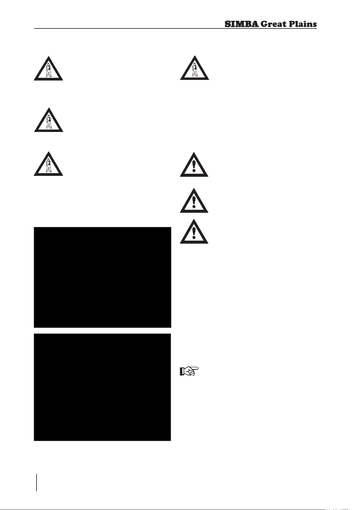
1.1 Safety Symbols
On the machine
Read and observe the Operating Instructions before
starting up the machine!
Parts may fly off during
operation. Keep a safe
distance away from the
machine!
Keep clear of the working
range of foldable machine
components!
Watch out for escaping
pressurised uids! Follow
the instructions in the Operating Instructions!
Never reach into areas
where there is a danger of
being crushed by moving
parts!
No passengers are allowed
on the machine!
Never reach into any revolving parts!
Operating Instructions
9CultiPress
Page 10

1. Safety Data
R e f e r t o O p e r a t i n g
I n s t r u c t i o n s b e f o r e
attempting maintenance.
Operating Instructions:
The Operating Instructions distinguish
between three different types of warning and
safety instructions. The following graphic
symbols are used:
Important!
Risk of injury!
Risk of fatal and serious injuries!
It is important that all the safety instructions
contained in these Operating Instructions
and all the warning signs on the machine
are read carefully.
Ensure that the warning signs are legible.
Replace any signs that are missing or
damaged.
These instructions must be followed in order
to prevent accidents. Inform other users of
the warnings and safety instructions.
Do not carry out any operations which may
affect safe use of the machine.
All references to left and right in this manual
are made from the rear of the machine, facing
the direction of travel (unless otherwise
stated).
CultiPress
10
Operating Instructions
Page 11

1. Safety Data
1.2 Use for the Intended
Purpose
The Simba Great Plains CultiPress is
built using the latest technology and in
accordance with the relevant recognised
safety regulations. However, risks of
injury for the operator or third parties and
impairment of the machine or other tangible
assets can arise during use.
The machine is only to be operated when
in a technically perfect condition and for the
intended purpose, taking into consideration
safety and risks and following the Operating
Instructions. In particular, faults that can
impair safety are to be remedied immediately.
Origin al parts and accessories from
Simba Great Plains have been specially
designed for this machine. Spare parts
and accessories not supplied by us have
not been tested or authorised. Installation
or use of non-original Simba Great Plains
products may have a detrimental effect on
specic design features of the machine and
affect the safety of machine operators and
the machine itself. Simba Great Plains will
accept no liability for damage resulting from
the use of non-original parts or accessories.
The Simba Great Plains CultiPress is
designed solely as a cultivation implement.
Use for any other purpose, e.g., as a means
of transport, will be deemed to be improper
use. Simba Great Plains will accept no
liability for damage resulting from improper
use. The risk will be borne solely by the
operator.
Use of the Cultipress behind high power
tractors (in excess of 40% above the
maximum recommended) can lead to high
loads and stresses which can cause long
term structural damage to the chassis and
key components. Such overloading can
compromise safety and is to be avoided.
1.3 Operational Safety
The machine is to be put in operation
only after instruction has been provided
by an employee of the authorised dealer
or an employee of Simba Great Plains.
The “Machine Registration” form is to be
completed and returned to your dealer.
All protective and safety equipment, such
as removable protective equipment, must
be in place and functioning reliably before
the machine is put in use.
Check screws and bolts regularly
for tig htn ess and re tig hte n if
necessary.
In the event of malfunctio ns,
stop and secure the machine
immediately.
Ensure that any faults are remedied
immediately.
1.4 No Liability for
Consequential Damage
The CultiPress has been manufactured
with great care. However, problems may
still occur when it is used for the intended
purpose. These may include:
• Worn wearing parts.
• Damage caused by external factors.
• Incorrect driving speeds.
• Incorrect setting of the unit (incorrect
attachment, non-adherence to the Setting
instructions).
Therefore, it is crucial to always
check your machine before and
durin g operat ion for c orrect
operation and adequate application
accuracy.
Compensation claims for damage which has
not occurred to the machine is excluded.
This includes any consequential damage
resulting from incorrect operation.
Operating Instructions
11CultiPress
Page 12
1. Safety Data
1.5 Road Trafc Safety
When driving on public roads, tracks and
areas, it is important to observe the relevant
road traffic laws as well as the specific
regulations relating to this machine.
Pay attention to the permitted axle
loads, tyre carrying capacity, and
total weight in order to maintain
adequate braking and steerability
(these gures are shown on the
serial plate).
Passengers on the machine are
strictly forbidden!
Max. road transport speed 16mph
(25km/h).
1.6 Accident Prevention
In addition to the Operating Instructions, it is
important to observe the accident prevention
regulations specied by agricultural trade
associations. It is the Operator’s responsibility
to ensure that all other persons are excluded
from the danger zones surrounding or on the
machine during its operation.
It is the Owner’s responsibility to ensure:
• the Operator is trained and competent to
use the machine & tractor,
• the tractor is suitable for the machine
• adequate Risk and COSHH assessments
have been undertaken regarding th e
machine’s use. Specically, these include
issues concerning contact with the soil,
dust, crop residues, chemicals, lubricants
and other compounds during operation or
maintenance, and the possibility of stones
being ejected at high speed during work.
Beware of trapping hazards when
manipulating the parking stands
or other moving parts. Ensure
any heavy components are fully
supported when removing pins /
bolts.
1.6.1 Hitching-up the
machine
There is a risk of injury when hitching/
unhitching the machine. Observe the
following:
• Secure the machine against rolling.
• Take special care when reversing the
tractor!
• There is a risk of being crushed between
the machine and the tractor!
• Park the machine on rm, level ground.
1.6.2 On the Hydraulic System
Do not connect the hydraulic lines to the
tractor until both hydraulic systems (machine
and tractor) are depressurised.
Any hydraulic system containing
an accumulator can re main
under pressure permanently
(even after following manual
depressurisation procedur es
with a t ractor / implement
combination). It is therefore
important to check all lines, pipes,
and screw connections regularly
for leaks and any recognisable
external damage.
The hydraulic circuit contains
specialised ttings which should
not be tampered with under any
circumstances. Do not attempt
to modify hose routings or hose
clamping arrangements, doing so
my cause serious damage to the
machine and/or injury.
CultiPress
12
Operating Instructions
Page 13

1. Safety Data
Only use appropriate aids when checking
for leaks. Repair any damage immediately.
Spurting oil can cause injuries and res!
In case of injury, contact a doctor immediately.
The socket and plugs for the hydraulic
connections between the tractor and the
machine should be colour-coded in order
to avoid incorrect use.
Fig. 1.01: HydraulicTaps
1.6.3 Changing Equipment
• Secure the machine to prevent it from
accidentally rolling away!
• Use suitable supports to secure any
raised frame sections suspended above
you!
• Caution! Risk of injury due to projecting
parts!
Never climb on to rotating parts
such as the roll unit. These parts
may rotate causing you to slip and
suffer serious injury!
Removing components during
mai nten ance may affect the
stability of the machine. Ensure
it is fully supported in case of
unexpected weight shifts.
1.6.4 During Operation
Ensure that the working range and the area
around the machine are clear (children!)
before operating the machine.
Always ensure adequate visibility!
Do not stand on the machine while it is in
operation!
Operators must have a valid driving licence
in order to drive on public roads. In the
operating area, the operator is responsible
for third parties.
The person in charge must:
• provide the operator with a copy of the
Operating Instructions, and
• ensure that the operator has read and
understood the instructions.
• make sure that the operator is aware of the
specic regulations relating to the machine
when driving on public roads.
1.7 Servicing &
Maintenance
Ensure that regular checks and inspections
are always carried out within the periods
required by law or specified in these
Operating Instructions.
When carrying out service and maintenance
work always:
• switch off the tractor engine and remove
the ignition key.
• wait until all the machine parts have
stopped moving.
• depressurise the hydraulic system.
Many hydraulic circuits contain lock or
overcentre valves which can retain pressure
in the lines even after depressurising the
tractor side of these circuits. If in doubt,
consult trained personnel (such as your
local Simba Great Plains Dealer) to ensure
such valves are depressurised to the correct
procedure before removing or servicing
any parts connected downstream of these
valves.
Operating Instructions
13CultiPress
Page 14

1. Safety Data
Check all hydraulic lines for leaks, loose
connections, chafe marks and damage.
Remedy any deciencies immediately! Pay
particular attention to hose renewal intervals
as outlined in the specic sections which
follow. ALL hydraulic hoses have a safe
maximum working life of 6 (SIX) years from
date of installation, provided they remain in a
safe condition. Hoses which exceed 6 years
of age should be replaced, or inspected and
certied by a suitably qualied person to
have an extended life period which should
be recorded.
Pay particular attention to those items which
require specialist service tools or training
to be carried out by qualied personnel. Do
not attempt to service these items yourself!
These include items retaining pressure (e.g.
accumulator circuits), or force (e.g. spring
tines), and DD Rolls of any type.
On a new machine tighten all nuts and
bolts after 5 hours work and again after 15
hours. This also applies to parts that have
been moved or replaced. After the initial 15
hours of work a once a week check should
be sufcient depending on daily work rates.
1.8 Operating Areas
The operating areas include the drawbar,
hydraulic connections and depth adjustment
equipment as well as all operating points
requiring maintenance.
All operating areas will be specied and
described in detail in the following chapters
on servicing and maintenance.
Observe all safety regulations included in
the section dealing with Safety, and in the
subsequent sections.
Prior to performing maintenance and
servicing work, ensure that the machine
is positioned on solid, level ground and is
secured to prevent it rolling away. Do not
use any parts to climb on to the machine
unless they are specically designed for
this purpose.
Before cleaning the machine with water,
steam jets (h igh-pr e ssure c leani n g
apparatus) or other cleaning agents, cover
all openings into which, for reasons of safety
or operation, no water, steam or cleaning
agents are to penetrate (bearings, for
instance).
Lubricate all the lubricating points to force
out any trapped water.
When carrying out servicing and maintenance
work, retighten any loose screw connections.
1.9 Authorised Operators
Onl y those per sons who hav e been
authorised and instructed by the operator
may operate the machine. The operator
must be at least 16 years of age.
1.10 Protective
Equipment
For operation and maintenance, you require:
• Tight tting clothing.
• Strong protective gloves (to provide
protection against sharp-edged machine
components).
• Protective goggles (to stop dirt getting into
your eyes).
When servicing the machine take precautions
against soil, dust, seed coatings, oil or any
other hazardous substances that you might
encounter.
CultiPress
14
Operating Instructions
Page 15

2. Transportation / Installation
2. Transportation and
Installation
Transportation and initial installation of the
machine are described in this chapter.
2.1 Delivery
The machine is normally delivered fully
assembled.
• The machine can be lifted off with a crane
or other suitable lifting equipment.
• The machine should be hitched to a
tractor and driven off a low-loader.
2.2 Transportation
The CultiPress can be transported on public
roads by hitching it up to a tractor or on a
low-loader.
2.3 Installation
When c a rryin g out ins t allat i on and
maintenance work there is a higher risk
of injury. It is important that you familiarise
yourself with the machine and read the
Operating Instructions beforehand.
Operator instruction and initial installation of
the machine are carried out by our service
technicians or authorised distributors.
The machine must not be used in any way
beforehand! The machine can only be
released for operation after instructions have
been provided by our service technicians or
authorised distributors.
• If any modules or parts have been
removed for transportation, these shall
be mounted by our service technicians/
authorised dealers before the instruction
takes place.
• It is important to observe the permitted
d i m e nsi o n s a n d w e igh t s wh e n
transporting the machine.
• If the machine is transported on a trailer
or a low-loader, it must be secured using
straps or other devices.
• Before transporting the machine on
public roads, it must be adjusted to
its transportation position and the
stipulations relating to road transportation
fullled.
• The maximum permissible speed is 25
km/h.
• Check all important screw connections!
• Lubricate all nipples and joints!
• Check all hydraulic connections and lines
for damage.
Operating Instructions
15CultiPress
Page 16
2. Transportation / Installation
2.4 Hitching Up
When hitching-up the machine,
ensure that no-one is between the
tractor and the machine.
When the CultiPress is parked for
extended periods of time it should
ideally be left in the unfolded,
i.e. work, position for stability,
safety and ease of access for
maintenance. However, parking
the CultiP ress in th e folded
position (using the parking stands
provided) is acceptable in the
normal course of operation.
Tractor Oil Flow Adjustment: As a general rule the trac-
tor oil ow rate should be set in
the lowest setting before starting.
This can then be increased to allow the desired rate of operation
as applicable. This will minimise
excessive oil ow and consequent
power usage and heat generation.
2.4.1 Hitching up a Tractor to
the CultiPress / Preparing for
Transport
Rigid Machines (3.3m and 4.0m):
1. Couple the four hydraulic hoses to the
tractor ensuring that the two levelling
board hoses are together and the two
drawbar cylinder hoses are together.
2. Use the hydraulics to raise or lower the
height of the shackle before hitching up
to the tractor drawbar clevis.
Do not use the tractor pick-up
hitch to attach the machine to the
tractor. This could cause damage
to the tractor and the machine.
3. Carefully operate the hydraulics to
lower the drawbar and tilt the CultiPress
onto the road transport wheels. Fully
extend the drawbar cylinder.
4. Fully raise the levelling board.
Do not open taps while tractor
hydraulics are in oat.
The hoses in the lift circuit have
a maximum rated pressure of
415bar, and should be replaced
every 6 years. Other components
in this locking circuit have a maximum rated pressure of at least
350bar.
5. Close the tap on the drawbar cylinder.
Folding Machines
1. Couple the six hydraulic hoses to the
tractor ensuring that the two wing
hoses are together, the two drawbar
cylinder hoses are together and the two
levelling board hoses are together.
2. Use the hydraulics to raise or lower the
height of the shackle before hitching up
to the tractor drawbar clevis.
Do not use the tractor pick-up
hitch to attach the machine to the
tractor. This could cause damage
to the tractor and the machine.
(4.6m, 5.5m and 6.6m):
CultiPress
16
Operating Instructions
Page 17
2. Transportation / Installation
3. Carefully operate the hydraulics to
lower the drawbar and tilt the CultiPress
onto the road transport wheels. Fully
extend the drawbar cylinders.
4. This al lows t he levelling boards
to be fully raised so that when the
CultiPress is folded the levelling
boards do not protrude beyond the 3m
transport width. Fully raise the levelling
boards.
5. Operate the hydraulics to fold the
wings.
6. Ensure that the wing strap is tted to
tie the two wing sections together.
7. Ensure that parking stands are locked
in the transport position, ie. fully raised.
Beware of sudden or uncontrolled
movements if the taps are opened
with the hydraulics in oat. Do
not open taps with the tractor
hydraulics in oat.
4. Operate the hydraulics to fully unfold
the wings.
5. Lower the machine to the ground until
the chassis is level front to rear or the
drawbar cylinders touch the depth
stops.
2.5.2 Folding into the
Transport Position
1. Fully raise the levelling boards so that
they do not protrude beyond the 3m
transport width.
2.5 Folding and Unfolding
Folding Machines (4.6m, 5.5m and 6.6m)
Check for exposed persons when
lowering / unfolding the machine.
Do not climb on the machine to t
or remove the transport strap, this
should be done from the ground.
2.5.1 Unfolding into the Work
Position
1. Ensure that the parking stands are in
the fully raised position.
2. Remove the transport strap from the
rear wing cylinders. Stow the transport
strap on the lights as shown in Fig.
2.01.
2. Raise the machine onto the transport
wheels.
3. Operate the hydraulics to fully fold the
wings.
4. Fit the transport strap across the pins
on the rear wing cylinders for transport
safety.
5. Close the taps on the hosemast.
6. Lower the parking stands if th e
CultiPress is to be unhitched from the
tractor in the folded position.
Fig. 2.01: Transport Strap Stowage in Work
3. Open the taps on the hosemast.
17CultiPress
Operating Instructions
Page 18

2. Transportation / Installation
2.6 Air Brake Coupling
Procedure
Please refer to the following procedure
when coupling or decoupling any item of
Simba Great Plains machinery tted with an
AIR brake or AIR and HYDRAULIC brake
system. Please note that this procedure
does not apply to any machines tted with
a HYDRAULIC system ONLY.
2.6.1 When Coupling
1. Reverse up to the machine and
connect the machine to the tractor as
instructed to in Section 2.4.1.
2. With the machine connected couple
the air lines. When coupling ensure the
yellow line is attached rst followed by
the red line.
3. Your brake hoses are now attached
and are ready for operation.
4. Continue with the coupling process as
instructed in Section 2.4.1.
4. Continue de-coupling the machine until
it is fully disconnected.
By following the above instructions
you will see that at NO point
in the coupling or decoupling
process has the red line been
left in the tractor on its own.
This is intentional and should be
considered the ‘rule’ to coupling
the hoses.
2.7 Preceding & Trailing
Implements
Adding a preceding or trailing
implement to the CultiPress will
affect the stability and handling
of the machine both in transport
and work.
2.7.1 Hitching a Disc Cultivator
to the CultiPress
1. Remove the transport straps from the
disc cultivator, exercise great CARE
when extending the axle cylinder.
2.6.2 When De-coupling
1. Bring the machine to the parking
position as instructed to in Section 2.9.
2. With the machine still connected to
the tractor remove the red brake line
followed by the yellow line.
3. Your brakes will now be ON and will
hold, ensuring they have been adjusted
and maintained correctly, the machine
in position. (note: if the machine‘s tank
is drained of air once all lines have
been detached the brakes will come off
(same situation as pushing the shunt
valve).
CultiPress
18
Operating Instructions
2. Reverse the disc cultivator up to the
CultiPress drawbar ensuring that the
two drawbars are aligned allowing
a slight clearance to e nable the
machines to be coupled together.
3. Lower the disc cultivator to the ground.
4. Connect the four hydraulic hoses from
the CultiPress into the disc cultivator
rear outlets ensuring that the two
wing hoses are together and the two
drawbar cylinder hoses are together.
Ensure that the folding circuits and lift
drawbar circuits are coupled correctly.
5. Raise the CultiPress drawbar above
the disc drawbar (200mm approx.).
Depth control shims may need to be
removed.
Page 19

2. Transportation / Installation
6. Raise the disc cultivator to the same
height as the CultiPress drawbar then
reverse the disc cultivator to couple the
two machines together.
7. Fit the drawbar pin.
8. Operate the hydraulics to lower the rear
axle and drawbar, tilting the CultiPress
onto the road transport wheels. Fully
extend the drawbar cylinders.
9. Fully raise the levelling boards.
10. Operate the hydraulics to fold the
wings.
11. Operate the hydraulics to lift the disc
cultivator into the transport position.
2.7.2 Transporting a CultiPress
Towed Behind a Disc Cultivator
With both machines in the transport position
i.e. raised and folded, the top frame of the
disc cultivator should be slightly nose down
or horizontal even when the downward load
from the CultiPress is applied to the drawbar
of the disc cultivator. The top frame should
NEVER be tail low in transport as this will
give a high negative loading on the tractor
which could lead to loss of traction to the
rear wheels.
Extreme caution must be taken when the
CultiPress is transported up steep gradients
and across side slopes. Higher drawbar
loading can be achieved by shortening the
drawbar cylinder.
12. Fit the disc cultivator transport straps.
13. Fit the CultiPress wing transport strap
to tie the two wing sections together.
14. Ensure that parking stands are locked
up in their work position.
When the CultiPress is used in tandem
with a disc harrow the disc should be set
to the operators manual i.e. front disc gang
to be 50mm closer to the ground than the
corresponding disc blade on the rear gang.
With both machines in the transport position
i.e. raised and folded, the top frame of the
disc cultivator should be slightly nose down
or horizontal even when the downward load
from the CultiPress is applied to the drawbar
of the disc cultivator.
Prior to leaving the eld to travel on a public
highway ensure that any clods of soil are
removed from the machine to prevent them
from fouling the road.
MAXIMUM ROAD TRANSPORT SPEED 16
MPH (25 km/h).
2.7.3 Changing from Work to
Road Transport (CultiPress
Towed Behind a Disc Cultivator)
1. Operate the hydraulics to raise the disc
and CultiPress.
2. Operate the hydraulics to fold the
wings on both the disc cultivator and
the CultiPress.
3. Fit th e transport str aps to both
machines.
The frame may be levelled by altering the
rearward tilt of the CultiPress to increase or
reduce the loading on the disc rear drawbar.
It may be necessary to shorten the
levelling springs until the top frame
of the disc harrow is horizontal or
slightly nose down before moving
the machines.
19CultiPress
Operating Instructions
Page 20
2. Transportation / Installation
Shortening the CultiPress drawbar cylinder
will increase the loading on the rear of the
disc frame. If necessary this can be used to
level the disc top frame for road transport.
2.7.4 Hitching a Rear Roll to
the CultiPress
Follow procedure 2.4 to couple a tractor to
the CultiPress. Once the tractor is safely
connected to the implement and in its folded
setting, raise the machine fully clear of the
ground.
Maximum rear drawbar vertical
loading = 650kg
1. Reverse the CultiPress up to the roller.
2. Align the CultiPress and roller drawbars,
lower the CultiPress to the ground and
depressurise the lift hydraulics.
3. Raise / lower the axle as required
to align the respective machines‘
drawbars and couple together.
4. Couple the rear roll to the lift circuit of
the CultiPress, ensuring that the hoses
are connected to the corresponding
circuit on the trailing machine.
2.8 When driving on the
road
When driving on the road the machine must
be converted to the transportation position.
When driving on the road, raise
the machine completely to prevent
the working elements dragging on
the ground.
2.9 Parking the machine
In order to avoid damage as a result of
moisture, the machine should be parked, if
possible, indoors or under cover.
When manoeuvring the machine,
pay attention to your surroundings.
Ensure that nobody is in the
manoeuvring area (watch for
children!).
• Park the machine on level and solid ground.
• Fit wheel chocks.
• With the machine raised move the parking
stands into position.
• Lower the machine onto the parking
stands ensuring that it is stable.
• Remove the drawbar pin and drive forward
slowly until hitch is clear of tractor drawbar.
• Lower the drawbar to the ground.
• Switch off the tractor.
• Disconnect hydraulic lines from the tractor.
5. Couple the rear roll wing (fold) circuit to
the wing (fold) circuit of the CultiPress.
6. Fully raise the CultiPress and the roll
clear of the ground.
7. Check that all transport straps / devices
are tted or closed.
CultiPress
20
Operating Instructions
If parking on uneven or sloping
ground unfold the machine and
lower rst to avoid instability.
Fig. 2.02. Wheel chocks
Page 21

3. Technical Data
3. Technical Data CultiPress
3.3m 4.0m 4.6m 5.5m 6.6m
Working Width 3300mm 4000mm 4600mm 5500mm 6600mm
Transport Width 3400mm 4100mm 2900mm 2900mm 2900mm
Transport Height 2700mm 2700mm 3600mm 3800mm 3990mm
Length 6400mm 6400mm 6800mm 6800mm 6800mm
Weight 3480Kg 3910Kg 5660Kg 6630Kg 7220Kg
Tractor Power Required * 115-130 140-160 160-180 195-220 230-260
Drawbar Load ** 515Kg 575Kg 1005Kg 1025Kg 1045Kg
Axle Load 2965Kg 3395Kg 4655Kg 5605Kg 6175Kg
Centre of Gravity *** 3400mm 4000mm 4400mm 4500mm 4600mm
* It is important to correctly match your implement to your tractor for optimum performance.
** Varies with lift, tilt and options.
*** Dimension from hitch in road transport.
Operating Instructions
21CultiPress
Page 22
4. Adjustment / Operation
4. Adjustment/Operation
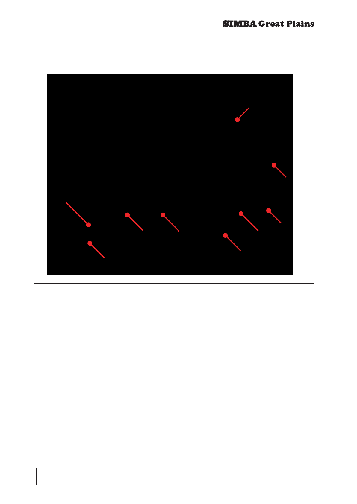
4.1 Description
8
7
9
2
1
Fig. 4.01: CultiPress
1. Drawbar
2. Shim Stowage
3. Parking Stands
4. Tines (Pro-Active shown)
5. Levelling Board
6. Intermeshed DD600 Rolls
7. Transport Wheels
8. Rear Drawbar (if tted)
9. Hydraulic Hose Stowage
The Simba Great Plains CultiPress is a
versatile implement designed to perform an
excellent shallow cultivation combined with
effective consolidation. The CultiPress may
be towed on its own or in tandem behind
another implement e.g. Disc Cultivator.
6
3
5
4
It can be used in reduced tillage systems
behind a disc cultivator to incorporate stubble
or to work down ploughing on medium to
heavy soil types. Like all Simba Great Plains
machines it features the latest innovations
which combine to give an efcient, well-built
unit with unrivalled reliability.
The CultiPress consists of two rows of
tines (either rigid or sprung) followed by a
hydraulically operated levelling board then
a double row of press rings.
The levelling board consists of a series of
sprung leaves with each leaf set between
each front ring. The levelling board carries
CultiPress
22
Operating Instructions
Page 23
4. Adjustment / Operation
soil ahead of the rings to ll low areas. The
sprung leaves crush clods as they pass
under the levelling board and align clods
with the front row of press rings.
The rear row of press roll rings are
intermeshed with the front row, overall ring
spacing across the machine is thereby
reduced to 115mm (4.5”). The action of
the second row of rings is to ensure that
large clods chopped by the front rings are
chopped a second time to reduce overall
clod size. The second row of rings are then
scraped by a set of rigid scrapers attached
to the rear gang beam.
The use of a CultiPress in tandem with a disc
cultivator can consolidate the straw / soil mix
through the soil prole, ensuring maximum
straw soil contact to increase the breakdown
process, minimise slug problems and leave
a rm weatherproof nish.
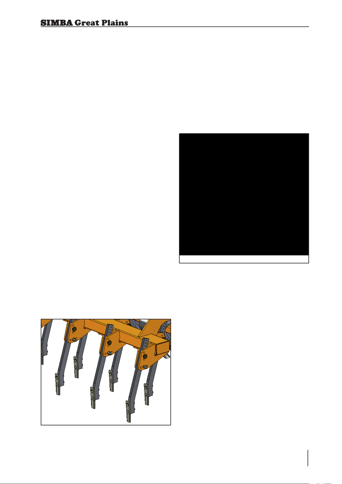
4.3 Pro-Active (Sprung)
Tines
The Pro-Active tines are designed to move
soil and shatter clods to a greater degree
than traditional rigid leading tines. The
ability to move in all directions (upwards and
sideways) allows them to clear stones and
other obstructions. They feature simple,
pinned tine depth adjustment for easy depth
variation.
4.2 Rigid Tines
The leading tines are individually adjusted,
utilising eighteen different height settings and
three different rake settings. Added security
of shear bolt protection ensures trouble free
operation in tough, arduous conditions.
The ability to effectively eradicate tractor
wheelings without moving dry clods onto
the wheelings is most important for even
germination.
Fig. 4.03: Pro-Active (Sprung) Tines
Fig. 4.02: Rigid Tines
23CultiPress
Operating Instructions
Page 24

4. Adjustment / Operation
4.4 Levelling Boards
The action of the levelling boards is to carry
and drop soil to level in front of the press
rings, to rub clod against clod for additional
soil breakdown, to force clods down into the
soil prole and to present remaining clods
passing between the leaves into the front
row of press rings.
4.5 Double Disc Roller
The standard DD600 roller is made up of
individual Double Disc (patented) Ring
segments.
The DD rings are designed to consolidate
the soil whilst cutting and crushing any clods.
Even in heavy, wet soils it can easily be
operated with minimal blockages occurring.
The rear DD roller carries a proportion of the
machine’s weight to ensure consolidation.
The corrugated surface left by the roller is
weatherproof both for wet or dry situations.
Fig. 4.04a: Levelling Boards (on rigid tine models)
Fig. 4.04b: Levelling Boards (on Pro-Active tine
models)
Fig. 4.05: Double Disc Rollers
CultiPress
24
Operating Instructions
Page 25

4. Adjustment / Operation
4.6 Work Settings
In work the wing cylinders should be fully
extended. The gangs are able to oat over
any undulations on the ground due to their
oating frames.
Optimum performance has been found
to be achieved when the press roll rings
have worn away the painted nish leaving
a smooth shiny surface. When the press
roll rings are new or rusty, soil may tend to
pick up on the surface and blockage may
occur, this will reduce when the rings are
shiny again.
The CultiPress should be run with the
chassis level front to rear by extending the
drawbar cylinders to the necessary position.
The cylinders should not be over extended
as this will remove the load on the front row
of rings which could lead to reduced drive
and hence blockage of the axles.
It is not necessary to tilt the CultiPress onto
the transport wheels during headland turns
whether the machine is used independently
or in tandem with a disc cultivator. Normally,
the CultiPress should be tilted sufciently for
the tines and levelling boards to clear the
ground (at which point the rear axle wheels
will still be clear of ground contact).
When reversing the CultiPress into corners
when working headlands ensure that the
levelling boards are fully raised and the
machine tilted onto the rear set of rings far
enough to allow the lower ends of the sprung
leaves to clear the ground.
General Rules when Setting
the CultiPress
• Run the chassis horizontal to give
even drive on both sets of rings.
• Run slightly tail low to give increased
clod cutting and consolidation in
harder conditions.
• In trashy conditions the use of the
levelling board may be limited due to
raking trash.
• Increase the rake angle of the levelling
board in spring time operation to carry
more soil for levelling.
• Reduce rake angle on levelling board
to hold soil and rub clod against clod in
harder conditions. This will also align
clods with the DD rings facilitating
better cutting.
4.6.1 Levelling Boards
With the chassis set level, lower the levelling
boards until they are carrying soil. The levelling boards will need to be set higher during
1st pass operations especially on ploughed
land where large clods may not be able to
pass under or between the sprung leaves.
The boards need to carry a certain amount
of soil to effect a levelling operation and also
to give a clod to clod crushing action. Use
the hydraulics to raise and lower the boards
to carry more or less soil when levelling the
headland troughs for example.
25CultiPress
Operating Instructions
Page 26

4. Adjustment / Operation
4.7 Pitch Control
Pitch control on the CultiPress is governed
by the quantity of shims tted to the depth
stops attached to the drawbar cylinders.
Increasing the number of shims will lift the
front of the chassis when lowered into the
work position. Ensure that equal quantities
of shims are added or removed from each
cylinder.
Running the CultiPress level allows the
front and rear press rings to give an even
consolidation and clod crushing action, with
the sprung leaves of the levelling board
aiding the clod crushing action, aligning the
clods for the front row of rings.
Running the machine significantly nose
down or raised will reduce the load on the
rear axle leading to loss of drive of the axle
and then blockage, together with a reduced
consolidation effect.
As such, especially under wet conditions,
it is advisable to check on the cultivation
effect of the CultiPress. Often the use of the
press 12 - 24 hours after the disc or longer
following the plough gives a far superior
surface consolidation effect.
When the CultiPress is used tilted onto the
rear row of rings the loading on the disc
cultivator or tractor drawbar is increased.
This will cause the rear of the disc to dig
deeper moving the rear gang to the right.
Shortening disc harrow levelling springs
should allow allow a disc harrow to pull
straight again. Equally, increased tractor
drawbar loadings will deepen wheelings
requiring more effort to eradicate these.
It is not necessary to tilt the CultiPress onto
the transport wheels during headland turns
whether the machine is used independently
or in tandem with a disc cultivator.
If any roll axle starts to block regularly, this
is generally an indication that the roll axle
is not tight. Failure to keep the axles tight
results in loss of drive between each pair of
rings allowing rings to turn individually on
the axle. Should this occur the axle must
be tightened immediately to prevent any
damage occurring to the axle shaft.
If the roll axles start to block regularly this
may also be an indication that the ground
conditions are too wet for the CultiPress to
be effective.
In practice it is possible to use the CultiPress
on ground conditions that are unsuitable to
achieve the desired effect, and it is usually
possible to operate the machine without
regular blockage under such unsuitable
conditions, assuming that the axles are tight
and rings smooth.
Full y ext endi ng th e dra wbar
cylinders and then reversing into
the headland furrow could lead to
damage of the cylinders.
CultiPress
26
Operating Instructions
Page 27

4. Adjustment / Operation
4.8 Using Shims
Before using shims to alter machine settings
ensure the machine is stationary and the
tractor is turned off with the keys out. Ensure
that all operators are clear of the machine
and that no load is being held on any existing
shims in the cylinder.
To t the shims hold them by the handle and,
using a rm action, clip them onto the rod
as shown in Fig. 4.06. They are removed by
using a nger to pull rmly on the handle.
Check the cylinders for damage
and debris before tting shims.
Only attempt to add or remove
shims using the handle. Trying to
manipulate shims using the jaws
could result in injury.
4.9 Work Instructions
Driving speed
The CultiPress can be driven at speeds of
up to 12 km/h.
This depends on the eld conditions (type
of soil, surface trash, etc.).
Drive more slowly if the conditions are
difcult or a rmer nish is required.
Beware of stones being thrown by
the spring action of tines returning
from their stressed state in work.
Parking the Machine
In order to avoid damage as a result of
moisture, the machine should be parked, if
possible, indoors or under cover.
When changing machine settings
ensure both sides of the machine
mirror each other. The left hand
cylinder should contain the same
amount of shims as the right, for
example. Failure to do this could
result in damage to the machine.
When manoeuvring the machine,
pay attention to your surroundings.
Ensure that nobody (children!) is
in the manoeuvring area.
• Park the machine on level and solid ground.
• Fit wheel chocks.
• With the machine raised move the parking
stands into position.
• Lower the machine onto the parking
stands ensuring that it is stable.
• Remove the drawbar pin and drive forward
slowly until hitch is clear of tractor drawbar.
• Lower the drawbar to the ground.
• Switch off the tractor.
• Disconnect hydraulic lines from the tractor.
Fig. 4.06: Shims
27CultiPress
Operating Instructions
Page 28

4. Adjustment / Operation
4.10 Checks
The working qu ality de pends on the
adjustments and checks made prior to and
during work, as well as on regular servicing
and maintenance of the machine.
Before beginning work it is therefore
important to carry out any necessary
servicing and to lubricate the machine as
required.
Checks prior to, and during
work:
• Is the machine correctly hitched up and
the coupling device locked?
• Have the hydraulic and electric lines
been connected according to the colour
coding?
• Is the machine in a level operating
position and the working depth set
correctly?
• Regularly inspect the machine for
damage and signs of overloading (stress
cracks on welded joints, frame distortion)
Working Elements
• Are the double disc rings and other
cul tiva tion to ols in a service able
condition?
• Are the scrapers still operable, so that
the rolls do not jam?
CultiPress
28
Operating Instructions
Page 29
5. Servicing and Maintenance
5. Servicing and
Maintenance
Follow the safety instructions for
servicing and maintenance.
Maintenance work should only
be undertaken with the machine
unfolded and lowered or on stands
with the hydraulic taps shut.
When working under the machine
ensure that the tractor handbrake
is on.
5.1 Servicing
Your machine has been designed and
constructed for maximum performance,
oper ation al efficie ncy an d ope rator
friendliness under a wide variety of operating
conditions.
5.3 Double Disc Axles
The axles on this roller are tensioned by the
main axle through the centre of the rings
and bearings.
Specialist equipment is required
for the disassembly of Double
Disc axles. Please consult your
dealer under any circumstances
that require disassembly of these
axles.
Maintenance of these rollers is limited to
daily greasing of the bearings to ush out
dirt, and regular inspection to ensure the
assemblies are tight, and scrapers are
correctly set. The axles can be tightened
provided the bearing pillar ‘U’ bolts are
loosened to avoid preloading the bearings
as they move sideways to each other.
Ensure the bearing pillars are re- tightened
to the mainframe after this.
Prior to delivery, your machine has been
checked at the factory and by your authorised
dealer to ensure that you receive a machine
in optimum condition.
To ensure trouble-free operation,
it is important that servicing and
maintenance work is performed at
the recommended intervals.
5.2 Cleaning
In order to ensure that the machine is
always in operating condition and to achieve
optimum performance, perform the cleaning
and servicing work at regular intervals.
Avoid cleaning the roll / disc bearings with
a high- pressure hose or a direct water jet.
The housing, screwed connections and ball
bearings are not watertight.
5.4 Hydraulics
A low oil ow should be used,
i.e., tractor tickover or low ow
selected.
The wing circuit is controlled by an
overcentre valve contained within
the manifold block which positively
locks oil ow until pressurised by
the tractor. System pressure can
be retained in the circuit even
after depressurisation of the
tractor quick release couplings.
Exercise extreme care when
checking the valve or circuits,
and under no circumstances
attempt to adjust or loosen ttings
without prior reference to your
authorised Simba Great Plains
dealer, and detailed maintenance
instructions.
Operating Instructions
29CultiPress
Page 30
5. Servicing and Maintenance
5.5 Tines
When performing maintenance
work on ti nes extreme care
should be taken. Wear goggles
and gloves at at all times when
maintaining tines.
Safely support unfolded machine
in raised position using taps
and stands before attempting
maintenance work on tines.
Do not attempt to assist tting tine
points with a steel headed hammer,
this can lead to splintering of the
metal due to its hardness, which
can cause injury. If tine fitting
requires assistance, a copper/
hide or plastic mallet should be
used.
5.6 Levelling Boards
Safely support the unfolded
machine in a raised position using
taps and stands before attempting
maintenance work on the levelling
boards.
5.7 Brakes & Wheel Hubs
The brakes should be tested before using for
the rst time and after the rst laden journey.
Check that the road and parking
brakes operate and release
correctly before using the
machine.
Check for hydraulic uid and air
leaks.
Brake and hub maintenance and
servicing should be carried out by
an authorised Simba Great Plains
dealer.
ENGAGE POINT
REMOVAL TOOL
STRIKE WITH
MALLET
5.8 Preparation for
Storage
If you need to store the machine for a longer
period, observe the following points:
• Park the machine undercover if possible.
• Protect the roll / discs against rust. If
you need to spray the implements with
oil, use light biologically degradable oils,
e.g. rape oil.
Cover any rubber sections before
using oil sprays. These sections
mus t no t be oil ed. Remo ve
any traces of oil with a suitable
cleaning agent.
Fig. 5.01: Knock-on Tine Point Removal Tool
CultiPress
30
Operating Instructions
Page 31

5. Servicing and Maintenance
5.9 Operator Support
If you have a problem, please contact your
dealer. They will endeavour to solve any
problems which may occur and provide you
with support at all times.
In order to enable your dealer to deal with
problems as quickly as possible, it helps if
you can provide them with the following data.
Always state the:
• Customer Number
• Name and Address
• Machine Model
• Serial Number of Machine
• Date of Purchase and Operating Hours
• Type of Problem
5.10 Maintenance
On a new machine tighten all nuts and bolts
after 5 hours work and again after 15 hours.
This also applies to parts that have been
moved or replaced. After the initial 15 hours
of work a once a week check should be
sufcient depending on daily work rates.
Intervals
Apart from daily m a i ntenanc e , t h e
maintenance intervals are based on the
number of operating hours and time data.
Keep a record of your operating hours to
ensure that the specified maintenance
intervals are adhered to as closely as
possible.
Never use a machine that is due for
maintenance. Ensure that all deciencies
found during regular checks are remedied
immediately.
Avoid sharp-edged and pointed
parts (disc blades, etc.) when
working on the machine.
Place the machine on suitable
s u p p o r t s w h e n w o r k i n g
underneath! Do not work under
a machine which is not supported!
Operating Instructions
31CultiPress
Page 32

5. Servicing and Maintenance
5.11 Maintenance Overview
Key
Inspect
Lights
L
Grease
Drawbar
Pivots
50 Hours
Before Each Use
L
Wheel Nut Torque:
270Nm
Tyres:
500x/50-17 14 Ply
Max Tyre Pressure:
50psi / 3.5bar
Before Each Use
Transport
Strap
Before Each Use
Lev. Board
Pivot
50 Hours
DD Axles
L
Parking
Stands
Before Each Use
Wing
Pivots
L
50 Hours
Tines
DD Roll
Lev. Board
10 Hours
L
10 Hours
CultiPress
32
Operating Instructions
Scrapers
10 Hours
L
Hubs
600 Hours
Hubs
Before Each Use
L
Page 33

5. Servicing and Maintenance
5.12 Lubricating the
Machine
Please read the section below carefully
before lubricating the machine.
The machine must be lubricated regularly in
order for it to remain serviceable. Regular
lub ricatio n also contrib utes to wards
extending the service life of your machine.
The recommended lubricating intervals are
specied in “Maintenance Overview”.
After it has been washed using a highpressure hose or steam cleaned, the
machine should always be lubricated using
a grease gun.
5.13 Handling of
Lubricants
Please ensure that you read the following
ins truc tion s as we ll as the releva nt
information. This also applies to any of your
employees who handle lubricants.
Hygiene
Lubricants do not present a health hazard
provided they are used for their specied
purpose.
In the case of prolonged skin contact,
lubricants, especially low-viscosity oils, may
remove the natural layer of fat contained in
the skin, resulting in dryness and possible
irritation.
It is important to take extreme care when
handling waste oil as it may contain other
irritants.
Vapours given off by cleaning agents and
oils are also a potential health hazard.
You should therefore not carry any oily cloths
around. Change soiled work clothing as
soon as possible.
Always exercise extreme care and observe
the recommended hygiene rules when
handling mineral oil products. Details of
these handling regulations can be found
in information provided by the health
authorities.
Storage and Handling
• Always store lubricants where they
cannot be accessed by children.
• Never store lubricants in open or
unlabelled containers.
Fresh Oil
• Apart from taking the usual care and
observing hygiene rules, there is no need
to take any special precautions when
handling fresh oil.
Waste Oil
• Waste o i l c an c o n t a in h a r m f ul
contaminants which may cause skin
cancer, allergies and other illnesses.
Attention!
Oil is a toxic substance. Should you swallow
any oil, do not try to vomit. Contact a doctor
immediately.
Protect your hands with barrier cream or
wear gloves to avoid contact with the skin.
Wash off any traces of oil thoroughly with
soap and hot water.
• Wash your skin thoroughly with soap
and water.
• Use special cleaning agents to clean any
dirt off your hands.
• Never wash oil residue from your skin
with petrol, diesel fuel or parafn.
• Avoid skin contact with any oily clothing.
• Do not keep any oily rags in your pockets.
• Wash soiled clothing before wearing it
again.
• Ensure that any oily footwear is disposed
of in the proper manner.
Operating Instructions
33CultiPress
Page 34

5. Servicing and Maintenance
Measures in case of injury
through oil
Eyes:
Should any oil be splashed into your eyes,
rinse with water for 15 minutes. If the eye is
still irritated, contact a doctor immediately
If oil is swallowed
If oil is swallowed, it is important not to induce
vomiting. Contact a doctor immediately.
Skin irritation caused by oil
In case of prolonged skin contact, wash off
the oil with soap and water.
Oil Spills
Use either sand or a suitable granular
absorbent to soak up any spilt oil. Dispose
of the oil-contaminated absorbent in the
proper manner.
5.14 Lubricants &
Hydraulic Oil
Hydraulic System
The hydraulic uid from the tractor is mixed
with the hydraulic uid from the machine.
The supplied machine hydraulic system
contains Total AZOLLA ZS 32 oil.
Lubricants
All lubricating points on the machine can be
lubricated with multigrade lubricating grease
as specied in DIN 51825 KP/2K - 40.
Oil Fires
Never use water to extinguish an oil re.
The oil will oat on the water causing the
re to spread.
Burning oil-lubricant must be extinguished
using a carbon dioxide powder or foam
extinguisher. Always wear respiratory
equipment when dealing with res of this
type.
Waste Oil Disposal
Oil-contaminated waste and used oil must
be disposed of in accordance with current
legislation.
Waste oil must be collected and disposed of
in accordance with local regulations. Never
pour used oil into unsealed sewage systems
or drains or onto the ground.
CultiPress
34
Operating Instructions
Page 35

6. Faults and Remedies
6. Faults and Remedies
CultiPress Troubleshooting
Fault Possible Cause Remedy
Front roll axle starts to
block regularly.
Rear roll axle starts to
block regularly.
Levelling boards drop at
headland turns.
Levelling boards become
unphased.
Machine running too tail
low.
Front to rear tracking out of
alignment.
Roll axle is not tight. Tighten axle.
Ground conditions too wet. Wait for more suitable
Machine running too tail
high.
Roll axle is not tight. Tighten axle.
Front to rear tracking out of
alignment.
Ground conditions too wet. Wait for more suitable
Rear roll scrapers incorrectly adjusted.
Tractor spool valve in oat
position.
Tractor spool valve in oat
position.
Shorten work drawbar
cylinder until chassis is
horizontal or just tail low.
Reduce quantity of shims in
depth stop unit.
Reset ring centres to run
rear rings centrally between
the front rings.
ground conditions.
Lengthen work drawbar
cylinder until chassis is
horizontal or just tail low.
Increase quantity of shims
in depth stop unit.
Reset ring centres to run
rear rings centrally between
the front rings.
ground conditions.
Set scrapers to run just
clear of rings and centrally
between each ring.
Operate levelling boards
using pressure only.
Operate levelling boards
using pressure only.
Operating Instructions
35CultiPress
Page 36

Notes
Space for Notes:
CultiPress
36
Operating Instructions
Page 37

7. Parts and Assembly
7. Parts & Assembly
7.1 Table of contents
Rigid Tine CultiPress ............................................................................. 40
3.3m Rigid Machine ....................................................................................................... 40
4m Rigid Machine .......................................................................................................... 42
4.6m Folding Machine ................................................................................................... 44
5.5m Folding Machine ................................................................................................... 46
6.6m Folding Machine ................................................................................................... 48
Sprung Tine CultiPress .......................................................................... 50
3.3m Rigid Machine ....................................................................................................... 50
4m Rigid Machine .......................................................................................................... 52
4.6m Folding Machine ................................................................................................... 54
5.5m Folding Machine ................................................................................................... 56
6.6m Folding Machine ................................................................................................... 58
Front and Rear Drawbars ...................................................................... 60
Rigid Machine Drawbar Assembly ................................................................................. 60
Folding Machine Drawbar Assembly ............................................................................. 62
Rear Drawbar Assembly ................................................................................................ 64
General Assemblies ............................................................................... 66
3.3m Mainframe Assembly - Rigid Tine CultiPress........................................................ 66
3.3m Mainframe Assembly - Sprung Tine CultiPress .................................................... 68
4m Mainframe Assembly - Rigid Tine CultiPress........................................................... 70
4m Mainframe Assembly - Sprung Tine CultiPress ....................................................... 72
4.6m Mainframe Assembly ............................................................................................ 74
5.5m & 6.6m Mainframe Assembly ................................................................................ 76
6 Stud Hub Assembly .................................................................................................... 78
Rigid Machine - Wiring Loom ........................................................................................ 80
Folding Machine - Wiring Loom ..................................................................................... 82
3.3m Rigid Machine - Front lights .................................................................................. 84
4.0m Rigid Machine - Front lights .................................................................................. 86
3.3m Rigid Machine - Rear lights .................................................................................. 88
4.0m Rigid Machine - Rear lights .................................................................................. 90
Folding Machine - Rear lights ........................................................................................ 92
Folding Machine - Rear lights ........................................................................................ 94
4.6m Wing Carrier Assembly ......................................................................................... 96
5.5+6.6m Wing Carrier Assembly .................................................................................. 98
Wings - Rigid Tine CultiPress .............................................................. 100
4.6m LH Wing Assembly (Complete)........................................................................... 100
4.6m RH Wing Assembly (Complete) .......................................................................... 102
5.5m LH Wing Assembly (Complete)........................................................................... 104
5.5m RH Wing Assembly (Complete) .......................................................................... 106
6.6m LH Wing Assembly (Complete)........................................................................... 108
6.6m RH Wing Assembly (Complete) ...........................................................................110
Operating Instructions
37CultiPress
Page 38

7. Parts and Assembly
4.6m LH Wing Assembly ..............................................................................................112
4.6m RH Wing Assembly ..............................................................................................114
5.5m LH Wing Assembly ..............................................................................................116
5.5m RH Wing Assembly ..............................................................................................118
6.6m LH Wing Assembly ............................................................................................. 120
6.6m RH Wing Assembly ............................................................................................. 122
Wings - Sprung Tine CultiPress ........................................................... 124
4.6m LH Wing Assembly (Complete)........................................................................... 124
4.6m RH Wing Assembly (Complete) .......................................................................... 126
5.5m LH Wing Assembly (Complete)........................................................................... 128
5.5m RH Wing Assembly (Complete) .......................................................................... 130
6.6m LH Wing Assembly (Complete)........................................................................... 132
6.6m RH Wing Assembly (Complete) .......................................................................... 134
4.6m LH Wing Assembly ............................................................................................. 136
4.6m RH Wing Assembly ............................................................................................. 138
5.5m LH Wing Assembly ............................................................................................. 140
5.5m RH Wing Assembly ............................................................................................. 142
6.6m LH Wing Assembly ............................................................................................. 144
6.6m RH Wing Assembly ............................................................................................. 146
Pro-Active Tine Assembly ............................................................................................ 148
Tine Assembly - Straight Tine ...................................................................................... 150
Tine Assembly - Cranked Tine, 220mm Sweep ........................................................... 152
Levelling Boards - Rigid Tine CultiPress ............................................. 154
3.3m Levelling Board Assembly ................................................................................. 154
4m Levelling Board Assembly ..................................................................................... 156
4.6m Levelling Board Assembly LH ............................................................................. 158
4.6m Levelling Board Assembly RH ............................................................................ 160
5.5m Levelling Board Assembly LH ............................................................................. 162
5.5m Levelling Board Assembly RH ............................................................................ 164
6.6m Levelling Board Assembly LH ............................................................................. 166
6.6m Levelling Board Assembly RH ............................................................................ 168
Levelling Boards - Sprung Tine CultiPress .......................................... 170
3.3m Levelling Board Assembly ................................................................................. 170
4m Levelling Board Assembly ..................................................................................... 172
4.6m Levelling Board Assembly LH ............................................................................. 174
4.6m Levelling Board Assembly RH ............................................................................ 176
5.5m Levelling Board Assembly LH ............................................................................. 178
5.5m Levelling Board Assembly RH ............................................................................ 180
6.6m Levelling Board Assembly LH ............................................................................. 182
6.6m Levelling Board Assembly RH ............................................................................ 184
Double Disc Roll ................................................................................... 186
Double Disc Pillar Assembly ........................................................................................ 186
Double Disc Axle Assembly 5 Rings ............................................................................ 188
Double Disc Axle Assembly 7 Rings ............................................................................ 190
Double Disc Axle Assembly 8 Rings ............................................................................ 192
Double Disc Axle Assembly 9 Rings ............................................................................ 194
CultiPress
38
Operating Instructions
Page 39

7. Parts and Assembly
Brakes .................................................................................................. 196
Rigid Machine Air Brakes ............................................................................................ 196
Rigid Machine Hydraulic Brakes.................................................................................. 198
Folding Machine Air Brakes ......................................................................................... 200
Folding Machine Hydraulic Brakes .............................................................................. 202
Hydraulics ............................................................................................ 204
Rigid Machine Lift Circuit ............................................................................................. 204
Rigid Machine Optional Lift Circuit .............................................................................. 206
Rigid Machine Levelling Board Circuit ......................................................................... 208
Folding Machine Lift Circuit ......................................................................................... 210
Folding Machine Wing Circuit ...................................................................................... 212
Folding Machine Optional Lift Circuit ........................................................................... 214
Folding Machine Optional Wing Circuit ....................................................................... 216
Folding Machine Lev. Board Circuit ............................................................................. 218
Decals .................................................................................................. 220
3.3m Decals................................................................................................................. 220
4m Decals.................................................................................................................... 222
4.6m Decals................................................................................................................. 224
5.5m Decals................................................................................................................. 226
6.6m Decals................................................................................................................. 228
Operating Instructions
39CultiPress
Page 40

7. Parts and Assembly
A
ISSUE
ASSEMBLY
1
AS4360
1
3
4
2
TO SERIAL NO.
FROM SERIAL NO.
PART NO.
PEJ
02/11/2004
DATE:-
DRAWN:-
© 2009
SIMBA
7
6
5
8
DESCRIPTION:-
CULTIPRESS 3.3m WOB FULL ASSEMBLY RIGID TINE
CultiPress
40
Operating Instructions
Page 41

7. Parts and Assembly
CULTIPRESS 3.3m WOB FULL
AS4360
ITEM PART NO DESCRIPTION QTY COMMENTS
1
2
3
4
5
6
7
8
9
10
11
12
13
14
15
16
17
18
19
20
21
22
23
24
25
26
27
28
29
30
31
32
33
34
35
36
37
38
39
40
41
42
43
44
45
46
47
48
49
50
AS0642 AXLE ASSEMBLY - DD600 7 RINGS 4
AS4087 CULTIPRESS 3.3m WOB LEVELLING BOAR1
AS4357 CULTIPRESS REAR DRAWBAR 1
AS4362 CULTIPRESS 3.3m WOB MAIN FRAME ASS1
AS4364 CULTIPRESS WOB DRAWBAR 1
AS4372 LIGHT KIT FRONT 1
AS4374 CULTIPRESS 3.3m REAR LIGHT KIT 1
P17961 MANUAL - F/W CULTIPRESS 1
ASSEMBLY RIGID TINE
Operating Instructions
41CultiPress
Page 42

7. Parts and Assembly
4
A
ISSUE
2
ASSEMBLY
AS4359
1
3
TO SERIAL NO.
6
FROM SERIAL NO.
PART NO.
PEJ
01/11/2004
DATE:-
DRAWN:-
© 2009
SIMBA
5
6
8
CultiPress
42
Operating Instructions
6
7
9
DESCRIPTION:-
CULTIPRESS 4.0m WOB FULL ASSEMBLY RIGID TINE
Page 43

7. Parts and Assembly
CULTIPRESS 4.0m WOB FULL
AS4359
ITEM PART NO DESCRIPTION QTY COMMENTS
1
2
3
4
5
6
7
8
9
10
11
12
13
14
15
16
17
18
19
20
21
22
23
24
25
26
27
28
29
30
31
32
33
34
35
36
37
38
39
40
41
42
43
44
45
46
47
48
49
50
AS0684 AXLE ASSEMBLY - DD600 8 RINGS 2
AS0773 AXLE ASSEMBLY - DD600 9 RINGS 2
AS4086 CULTIPRESS 4.0m WOB LEVELLING BOAR1
AS4357 CULTIPRESS REAR DRAWBAR 1
AS4358 LIGHT KIT FRONT 1
AS4361 CULTIPRESS 4.0m WOB MAIN FRAME ASS1
AS4364 CULTIPRESS WOB DRAWBAR 1
AS4373 CULTIPRESS 4.0m REAR LIGHT KIT 1
P17961 MANUAL - F/W CULTIPRESS 1
ASSEMBLY RIGID TINE
Operating Instructions
43CultiPress
Page 44

7. Parts and Assembly
TITLE
COMPANYMASS KgCOSTCATEGORYCOMMENTSQTY
MATERIAL
DESCRIPTIONISSUEPART NO
149.72 2 CULTIPRESS 4.6m WING
CARRIER ASSEMBLY
BAS17521
221.46 1 CULTIPRESS 4.6m RH
LEVELLING BOARD COMPLETE
BAS17572
221.52 1 CULTIPRESS 4.6m LH
LEVELLING BOARD COMPLETE
BAS17583
1458.73 1 CULTIPRESS 2005 4.6m LH FULL
BAS18144
AAS3740
4
ISSUE
1
7
3
10
ASSEMBLY
FROM SERIAL NO. TO SERIAL NO.
PART NO.
KSL
DRAWN:-
03/08/2009
DATE:-
© 2009
SIMBA
1
6
CULTIPRESS 2011
9
5
2
12
11
8
8
MACHINE:-
DESCRIPTION:-
CULTIPRESS 2011 4.6m FULL ASSEMBLY 2x1 TINES
CultiPress
44
Operating Instructions
Page 45

7. Parts and Assembly
M
B
B
AS3740
CULTIPRESS 2011 4.6m
FULL ASSEMBLY 2x1 TINES
ITEM PART NO DESCRIPTION QTY COMMENTS
1
2
3
4
5
6
7
8
9
10
11
12
13
14
15
16
17
18
19
20
21
22
23
24
25
26
27
28
29
30
31
32
33
34
35
36
37
38
39
40
41
42
43
44
45
46
47
48
49
50
AS1752 CULTIPRESS 4.6m WING CARRIER ASSE
AS1757 CULTIPRESS 4.6m RH LEVELLING BOARD1
AS1758 CULTIPRESS 4.6m LH LEVELLING BOARD 1
AS1814 CULTIPRESS 2005 4.6m LH FULL ASSEM
AS1815 CULTIPRESS 2005 4.6m RH FULL ASSEM
AS3711 LIGHT KIT FRONT 1
AS3712 REAR LIGHT BRACKETS 1
AS3735 F/W CULTIPRESS DRAWBAR ASSEMBLY 1
AS3741 4.6m BRAKED AXLE CHASSIS ASSEMBLY 1
AS4357 CULTIPRESS REAR DRAWBAR 1
AS4402 CULTIPRESS 4.6m STICKER KIT 1
P17961 MANUAL - F/W CULTIPRESS 1
2
1
1
45CultiPress
Operating Instructions
Page 46

7. Parts and Assembly
TITLE
COMPANYMASS KgCOSTCATEGORYCOMMENTSQTYMATERIALDESCRIPTIONISSUEPART NOITEM
205.49 2 CULTIPRESS 5.5+6.6 WING
CARRIER
BAS17531
256.48 1 CULTIPRESS 5.5m LH
LEVELLING BOARD COMPLETE
BAS17652
256.55 1 CULTIPRESS 5.5m RH
LEVELLING BOARD COMPLETEE
BAS17663
1799.36
1
5.5m LH FULL ASSEMBLY 2x1
B
AS1816
AAS3739
4
1
ISSUE
ASSEMBLY
7
2
FROM SERIAL NO. TO SERIAL NO.
10
PART NO.
KSL
03/08/2009
DATE:-
DRAWN:-
© 2009
1
6
8
SIMBA
CULTIPRESS 2011
MACHINE:-
CultiPress
46
Operating Instructions
5
3
11
12
9
9
DESCRIPTION:-
CULTIPRESS 2011 5.5m FULL ASSEMBLY 2x1 TINES
Page 47

7. Parts and Assembly
D
AS3739
CULTIPRESS 2011 5.5m
FULL ASSEMBLY 2x1 TINES
ITEM PART NO DESCRIPTION QTY COMMENTS
1
2
3
4
5
6
7
8
9
10
11
12
13
14
15
16
17
18
19
20
21
22
23
24
25
26
27
28
29
30
31
32
33
34
35
36
37
38
39
40
41
42
43
44
45
46
47
48
49
50
AS1753 CULTIPRESS 5.5+6.6 WING CARRIER 2
AS1765 CULTIPRESS 5.5m LH LEVELLING BOARD 1
AS1766 CULTIPRESS 5.5m RH LEVELLING BOAR
AS1816 5.5m LH FULL ASSEMBLY 2x1 TINES 1
AS1817 5.5m RH FULL ASSEMBLY 2x1 TINES 1
AS3711 LIGHT KIT FRONT 1
AS3712 REAR LIGHT BRACKETS 1
AS3734 5.5+6.6m BRAKED AXLE CHASSIS ASSEM 1
AS3735 F/W CULTIPRESS DRAWBAR ASSEMBLY 1
AS4357 CULTIPRESS REAR DRAWBAR 1
AS4403 CULTIPRESS 5.5m STICKER KIT 1
P17961 MANUAL - F/W CULTIPRESS 1
1
47CultiPress
Operating Instructions
Page 48

7. Parts and Assembly
TITLE
COMPANYMASS KgCOSTCODECOMMENTSQTYMATERIALDESCRIPTIONISSUEPART NOITEM
205.49 2 CULTIPRESS 5.5+6.6 WING
CARRIER
BAS17531
287.30 1 CULTIPRESS 6.6m LH
LEVELLING BOARD COMPLETE
BAS17722
287.51 1
CULTIPRESS 6.6m RH
LEVELLING BOARD COMPLETE
B
AS1773
3
2060.28 1 6.6 LH FULL ASSEMBLY 2x1
TINES
BAS18184
AAS4206
ISSUE
1
7
8
10
4
ASSEMBLY
2
FROM SERIAL NO. TO SERIAL NO.
PART NO.
AGD
21/10/2004
DATE:-
DRAWN:-
6
© 2009
SIMBA
9
11
3
5
12
9
CULTIPRESS 2011
MACHINE:-
DESCRIPTION:-
CULTIPRESS 2011 6.6m FULL ASSEMBLY 2x1 TINES
CultiPress
48
Operating Instructions
Page 49

7. Parts and Assembly
D
AS4206
CULTIPRESS 2011 6.6m
FULL ASSEMBLY 2x1 TINES
ITEM PART NO DESCRIPTION QTY COMMENTS
1
2
3
4
5
6
7
8
9
10
11
12
13
14
15
16
17
18
19
20
21
22
23
24
25
26
27
28
29
30
31
32
33
34
35
36
37
38
39
40
41
42
43
44
45
46
47
48
49
50
AS1753 CULTIPRESS 5.5+6.6 WING CARRIER 2
AS1772 CULTIPRESS 6.6m LH LEVELLING BOARD 1
AS1773 CULTIPRESS 6.6m RH LEVELLING BOAR
AS1818 6.6 LH FULL ASSEMBLY 2x1 TINES 1
AS1819 6.6 RH FULL ASSEMBLY 2x1 TINES 1
AS3711 LIGHT KIT FRONT 1
AS3712 REAR LIGHT BRACKETS 1
AS3734 5.5+6.6m BRAKED AXLE CHASSIS ASSEM 1
AS3735 F/W CULTIPRESS DRAWBAR ASSEMBLY 1
AS4357 CULTIPRESS REAR DRAWBAR 1
AS4404 CULTIPRESS 6.6m STICKER KIT 1
P17961 MANUAL - F/W CULTIPRESS 1
1
49CultiPress
Operating Instructions
Page 50

7. Parts and Assembly
A
ISSUE
1
4
1
3
2
ASSEMBLY
AS4354
TO SERIAL NO.
FROM SERIAL NO.
PART NO.
PEJ
03/11/2004
DATE:-
DRAWN:-
© 2009
SIMBA
7
6
5
8
DESCRIPTION:-
CULTIPRESS 2011 3.3m WOB FULL ASSEMBLY PROACTIVE TINE
CultiPress
50
Operating Instructions
Page 51

7. Parts and Assembly
CULTIPRESS 3.3m WOB FULL
AS4354
ITEM PART NO DESCRIPTION QTY COMMENTS
1
2
3
4
5
6
7
8
9
10
11
12
13
14
15
16
17
18
19
20
21
22
23
24
25
26
27
28
29
30
31
32
33
34
35
36
37
38
39
40
41
42
43
44
45
46
47
48
49
50
AS0642 AXLE ASSEMBLY - DD600 7 RINGS 4
AS4061 CULTIPRESS LEVEL BOARD 3.3m 1
AS4356 CULTIPRESS 3.3m WOB MAIN FRAME ASS1
AS4357 CULTIPRESS REAR DRAWBAR 1
AS4364 CULTIPRESS WOB DRAWBAR 1
AS4372 LIGHT KIT FRONT 1
AS4374 CULTIPRESS 3.3m REAR LIGHT KIT 1
P17961 MANUAL - F/W CULTIPRESS 1
ASSEMBLY PROACTIVE TINE
Operating Instructions
51CultiPress
Page 52

7. Parts and Assembly
A
ISSUE
2
ASSEMBLY
AS4353
1
5
3
4
TO SERIAL NO.
FROM SERIAL NO.
PART NO.
PEJ
03/11/2004
DATE:-
DRAWN:-
© 2009
SIMBA
8
6
MACHINE:-
CultiPress
52
Operating Instructions
7
9
DESCRIPTION:-
CULTIPRESS 4.0m WOB FULL ASSEMBLY PROACTIVE TINE
Page 53

7. Parts and Assembly
CULTIPRESS 4.0m WOB FULL
AS4353
ITEM PART NO DESCRIPTION QTY COMMENTS
1
2
3
4
5
6
7
8
9
10
11
12
13
14
15
16
17
18
19
20
21
22
23
24
25
26
27
28
29
30
31
32
33
34
35
36
37
38
39
40
41
42
43
44
45
46
47
48
49
50
AS0684 AXLE ASSEMBLY - DD600 8 RINGS 2
AS0773 AXLE ASSEMBLY - DD600 9 RINGS 2
AS4062 CULTIPRESS LEVEL BOARD 4m 1
AS4355 CULTIPRESS 4.0m WOB MAIN FRAME 1
AS4357 CULTIPRESS REAR DRAWBAR 1
AS4358 LIGHT KIT FRONT 1
AS4364 CULTIPRESS WOB DRAWBAR 1
AS4373 CULTIPRESS 4.0m REAR LIGHT KIT 1
P17961 MANUAL - F/W CULTIPRESS 1
ASSEMBLY PROACTIVE TINE
Operating Instructions
53CultiPress
Page 54

7. Parts and Assembly
TITLE
COMPANYMASS KgCOSTCODECOMMENTSQTY
MATERIAL
DESCRIPTIONISSUEPART NO
ITEM
149.72 2
CULTIPRESS 4.6m WING
CARRIER ASSEMBLY
B
AS1752
1
23.99 A 1 LIGHT KIT FRONT AAS3 7112
38.41 A 1 REAR LIGHT BRACKETS AAS37123
348.26 1 F/W CULTIPRESS DRAWBAR
ASSEMBLY
AAS37354
1021.01 1 4.6m BRAKED AXLE CHASSIS
AAS37415
AAS4201
ISSUE
8
1
ASSEMBLY
FROM SERIAL NO. TO SERIAL NO.
10
3
5
7
8
2
PART NO.
AGD
27/10/2010
DATE:-
DRAWN:-
© 2009
SIMBA
9
6
12
11
4
DESCRIPTION:-
CULTIPRESS 2011 4.6 F/W FULL ASSEMBLY PROACTIVE TINE
CultiPress
54
Operating Instructions
Page 55

7. Parts and Assembly
M
AS4201
CULTIPRESS 2011 4.6 F/W FULL
ASSEMBLY PROACTIVE TINE
ITEM PART NO DESCRIPTION QTY COMMENTS
1
2
3
4
5
6
7
8
9
10
11
12
13
14
15
16
17
18
19
20
21
22
23
24
25
26
27
28
29
30
31
32
33
34
35
36
37
38
39
40
41
42
43
44
45
46
47
48
49
50
AS1752 CULTIPRESS 4.6m WING CARRIER ASSE
AS3711 LIGHT KIT FRONT 1
AS3712 REAR LIGHT BRACKETS 1
AS3735 F/W CULTIPRESS DRAWBAR ASSEMBLY 1
AS3741 4.6m BRAKED AXLE CHASSIS ASSEMBLY 1
AS4059 CULTIPRESS LEVEL BOARD 4.6m RH 1
AS4060 CULTIPRESS LEVEL BOARD 4.6m LH 1
AS4204 CULTIPRESS 4.6m LH FULL ASSEMBLY PR1
AS4205 CULTIPRESS 4.6m RH FULL ASSEMBLY P 1
AS4357 CULTIPRESS REAR DRAWBAR 1
AS4402 CULTIPRESS 4.6m STICKER KIT 1
P17961 MANUAL - F/W CULTIPRESS 1
2
55CultiPress
Operating Instructions
Page 56

7. Parts and Assembly
TITLE
COMPANYMASS KgCOSTCODECOMMENTSQTY
MATERIAL
DESCRIPTIONISSUEPART NO
ITEM
205.49 2 CULTIPRESS 5.5+6.6 WING
CARRIER
BAS17531
23.99 A 1 LIGHT KIT FRONT AAS37112
38.41 A 1 REAR LIGHT BRACKETS AAS37123
1096.55 1 5.5+6.6m BRAKED AXLE
CHASSIS ASSEMBLY
AAS37344
348.26 1 F/W CULTIPRESS DRAWBAR
AAS37355
AAS4202
ISSUE
8
3
1
6
10
ASSEMBLY
FROM SERIAL NO. TO SERIAL NO.
PART NO.
AGD
28/10/2010
DATE:-
DRAWN:-
© 2009
SIMBA
1
9
7
4
12
2
11
5
DESCRIPTION:-
CULTIPRESS 2011 5.5m FULL ASSEMBLY PROACTIVE TINE
CultiPress
56
Operating Instructions
Page 57

7. Parts and Assembly
AS4202
CULTIPRESS 2011 5.5m FULL
ASSEMBLY PROACTIVE TINE
ITEM PART NO DESCRIPTION QTY COMMENTS
1
2
3
4
5
6
7
8
9
10
11
12
13
14
15
16
17
18
19
20
21
22
23
24
25
26
27
28
29
30
31
32
33
34
35
36
37
38
39
40
41
42
43
44
45
46
47
48
49
50
AS1753 CULTIPRESS 5.5+6.6 WING CARRIER 2
AS3711 LIGHT KIT FRONT 1
AS3712 REAR LIGHT BRACKETS 1
AS3734 5.5+6.6m BRAKED AXLE CHASSIS ASSEM 1
AS3735 F/W CULTIPRESS DRAWBAR ASSEMBLY 1
AS4057 CULTIPRESS LEVEL BOARD 5.5m LH 1
AS4058 CULTIPRESS LEVEL BOARD 5.5m RH 1
AS4207 CULTIPRESS 5.5m LH FULL ASSEMBLY PR1
AS4208 CULTIPRESS 5.5m RH FULL ASSEMBLY P 1
AS4357 CULTIPRESS REAR DRAWBAR 1
AS4403 CULTIPRESS 5.5m STICKER KIT 1
P17961 MANUAL - F/W CULTIPRESS 1
Operating Instructions
57CultiPress
Page 58

7. Parts and Assembly
TITLE
COMPANYMASS KgCOSTCODECOMMENTSQTYMATERIALDESCRIPTIONISSUEPART NOITEM
205.49 2 CULTIPRESS 5.5+6.6 WING
CARRIER
BAS17531
23.99 A 1 LIGHT KIT FRONT AAS37112
38.41 A 1 REAR LIGHT BRACKETS AAS37123
1096.55
1
5.5+6.6m BRAKED AXLE
CHASSIS ASSEMBLY
A
AS3734
4
348.26 1
F/W CULTIPRESS DRAWBAR
A
AS3735
5
AAS4203
ISSUE
ASSEMBLY
8
1
7
FROM SERIAL NO. TO SERIAL NO.
10
3
4
PART NO.
AGD
28/10/2010
DATE:-
DRAWN:-
© 2009
SIMBA
1
9
11
CultiPress
58
Operating Instructions
5
6
2
12
DESCRIPTION:-
CULTIPRESS 2011 6.6m FULL ASSEMBLY PROACTIVE
Page 59

7. Parts and Assembly
W
O
AS4203
CULTIPRESS 2011 6.6 F/
FULL ASSEMBLY PROACTIVE TINE
ITEM PART NO DESCRIPTION QTY COMMENTS
1
2
3
4
5
6
7
8
9
10
11
12
13
14
15
16
17
18
19
20
21
22
23
24
25
26
27
28
29
30
31
32
33
34
35
36
37
38
39
40
41
42
43
44
45
46
47
48
49
50
AS1753 CULTIPRESS 5.5+6.6 WING CARRIER 2
AS3711 LIGHT KIT FRONT 1
AS3712 REAR LIGHT BRACKETS 1
AS3734 5.5+6.6m BRAKED AXLE CHASSIS ASSEM 1
AS3735 F/W CULTIPRESS DRAWBAR ASSEMBLY 1
AS4055 CULTIPRESS LEVEL BOARD RH 1
AS4056 CULTIPRESS LEVEL BOARD LH 1
AS4209 CULTIPRESS 6.6 LH FULL ASSEMBLY PR
AS4210 CULTIPRESS 6.6 RH FULL ASSEMBLY PRO1
AS4357 CULTIPRESS REAR DRAWBAR 1
AS4404 CULTIPRESS 6.6m STICKER KIT 1
P17961 MANUAL - F/W CULTIPRESS 1
1
59CultiPress
Operating Instructions
Page 60

7. Parts and Assembly
A
ISSUE
3
1
7
13
5
34
31
23
2
20
10
16
12
6
19
35
ASSEMBLY
AS4364
TO SERIAL NO.
FROM SERIAL NO.
PART NO.
AGD
11/02/2011
DATE:-
DRAWN:-
© 2009
SIMBA
22
30
24
22
25
15
8
8
21
17
9
4
32
11
18
27
14
33
26
28
29
DESCRIPTION:-
CULTIPRESS WOB DRAWBAR
CultiPress
60
Operating Instructions
Page 61

7. Parts and Assembly
R
AS4364
ITEM PART NO DESCRIPTION QTY COMMENTS
1
2
3
4
5
6
7
8
9
10
11
12
13
14
15
16
17
18
19
20
21
22
23
24
25
26
27
28
29
30
31
32
33
34
35
36
37
38
39
40
41
42
43
44
45
46
47
48
49
50
P00036 BOLT M30x180 GR. 8.8 2
P00071 NIPPLE - GREASE 1
P01274 PIN Ø25x115 1
P02007 NUT LOCK M12 1
P02010 NUT LOCK M24 1
P02011 NUT LOCK M30 2
P02484 LYNCH PIN CAT 2 1
P02600 WASHER FLAT M10 4
P02601 WASHER FLAT M12 1
P02789 BOLT M8x20 GR. 8.8 3
P03088 BOLT M12x60 GR. 8.8 1
P03763 WASHER FLAT M30 2
P04756 CYLINDER - Ø100x637 - 60 1
P05492 NUT LOCK 1" UNF 2
P05534 NUT LOCK M10 2
P05535 WASHER FLAT M8 3
P06651 BOLT M10x25 GR. 8.8 2
P08548 BOLT 1" UNFx7" GR. V 2
P08802 SHIM KIT 7 PIECE 1
P09075 BOLT M24x125 GRS 1
P09092 HOSE STOWAGE PLATE 1
P09112 CLAMP ½" BSP PAIR 8
P09113 CLAMP - TOP PLATE 4
P09521 HOSE MAST WOB CULTIPRESS 1
P10049 BOLT M8x25 STAUFF STACK 4
P10138 HITCH CAT3 - SLOTTED 1
P10173 POLYURETHANE BLOCK 1
P10174 15mm SHIM 1
P10176 POLYURETHANE BLOCK RETAINER 1
P10234 LOCK CLIP 3
P10278 BOLT M8x45 GR. 8.8 4
P10575 HITCH CAT4 ECONOMY - SLOTTED 1
P16360 CAT3-CAT2 BUSH INSERT 1
P17815 MANUAL HOLDER - COMPLETE 1
P18250 DRAWBAR - CULTIPRESS WOB 1
CULTIPRESS WOB DRAWBA
61CultiPress
Operating Instructions
Page 62

7. Parts and Assembly
TITLE COMPANYMASS KgCOSTCATEGORYCOMMENTSQTYMATERIALDESCRIPTIONISSUEPART NOITEM 2.07£4.44B 2Steel, High Strength Low AlloyBOLT M36x200 GR. 8.8AP000451 0.02£0.03B 1Steel - 43CNUT LOCK M12AP020072 0.50£1.23B 2Steel, High Strength Lo w AlloyNUT LOCK M36BP020123 0.00£0.01B 4Steel, Hi gh Strength Low AlloyWASHER FLAT M10 P026004 0.13 B 2EN 43A / S275J0WASHER FLAT M39 AP026095 0.07£0.08B 1Steel, Hi gh Strength Low AlloyBOLT M12x60 GR. 8.8AP030886 0.10£0.10B 4Steel, High Strength Lo w AlloyWASHER FLAT M30 P037637 KN PRODUCTS0.04£1.08B 4Steel - CrBoBUSH SPRUNG - Ø32xØ26x20BP041268 0.13£0.54B 4Steel, Hi gh Strength Low AlloyNUT LOCK 1" UNFAP054929 0.01£0.02B 2Steel, High Strength Low AlloyNUT LOCK M10AP0553410 0.00£0.02B 3Steel, High Strength Low AlloyWASHER FLAT M8AP0553511 0.66£3.10B 2Steel, High Strength Lo w AlloyBOLT 1" UNFx5" GR. V P0556712 0.86£3.43B 2Steel, High Strength Low AlloyBOLT 1" UNFx7" GR. V P0854813 1.23£38.18B 2 SHIM KIT 7 PIECECP0880214 0.00£0.01B 3Steel, High Strength Low AlloyWASHER SPRING M8 P0881715 0.36£3.00F 1Steel - 43AHOSE STOWAGE PLATEAP0909216 0.05£0.58B 9ABS PlasticCLAMP ½" BSP PAIR P0911217 0.06£0.22B 3Steel - 43CCLAMP - TOP PLATE P0911318 3.63 F 1 HOSE MASTCP0925219 0.02£0.02B 3Steel, High Strength Low AlloyBOLT M8x25 GR. 8.8AP0959720 0.02£0.55B 6Steel, High Strength Low AlloyBOLT M8x25 STAUFF STACKAP1004921 14.00£36.80M 1Steel - 50BHITCH CAT3 - SLOTTEDAP1013822 0.19 1Nylon-6/6POLYURETHANE BLOCKAP1017323 0.67 FFOR CULTIPRESS 2000 & UNIPRESS1 15mm SHIMAP1017424 0.22 FSHIM FOR 4m FREE FLOW1 5mm SHIMAP1017525 0.37 F 1Welded Steel MildPOLYURETHANE BLOCK RETAINERBP1017626 STAUFF0.00 B 6Stainless Steel, 440CLOCK CLIPAP1023427 0.02£0.04B 3Steel, High Strength Low AlloyBOLT M8x45 GR. 8.8AP1027828 15.99£36.80M 1Steel - 50BHITCH CAT4 ECONOMY - SLOTTEDAP1057529 0.03£0.04B 2Steel, High Strength Low AlloyBOLT M10x30 GR. 8.8AP1269030 299.22 F 1 CULTIPRESS 2009 F/W DRAWBARAP17 21631 0.53 B 1 MANUAL HOLDER - COMPLETEAP1781532
AAS3735
1
ISSUE
5
3
12
17
21
18
28
17
17
21
8
ASSEMBLY
FROM SERIAL NO. TO SERIAL NO.
27
27
14
8
7
PART NO.
31
KSL
01/07/2009
DATE:-
DRAWN:-
© 2009
7
304
9
6
SIMBA
16
20
15
11
32
19
4
10
2
13
25
24 23
9
22
CULTIPRESS
MACHINE:-
26
29
CultiPress
62
Operating Instructions
DESCRIPTION:-
F/W CULTIPRESS DRAWBAR ASSEMBLY
Page 63

7. Parts and Assembly
R
AS3735
F/W CULTIPRESS DRAWBA
ASSEMBLY 2011
ITEM PART NO DESCRIPTION QTY COMMENTS
1
2
3
4
5
6
7
8
9
10
11
12
13
14
15
16
17
18
19
20
21
22
23
24
25
26
27
28
29
30
31
32
33
34
35
36
37
38
39
40
41
42
43
44
45
46
47
48
49
50
P00045 BOLT M36x200 GR. 8.8 2
P02007 NUT LOCK M12 1
P02012 NUT LOCK M36 2
P02600 WASHER FLAT M10 4
P02609 WASHER FLAT M39 2
P03088 BOLT M12x60 GR. 8.8 1
P03763 WASHER FLAT M30 4
P04126 BUSH SPRUNG - Ø32xØ26x20 4
P05492 NUT LOCK 1" UNF 4
P05534 NUT LOCK M10 2
P05535 WASHER FLAT M8 3
P05567 BOLT 1" UNFx5" GR. V 2
P08548 BOLT 1" UNFx7" GR. V 2
P08802 SHIM KIT 7 PIECE 2
P08817 WASHER SPRING M8 3
P09092 HOSE STOWAGE PLATE 1
P09112 CLAMP ½" BSP PAIR 9
P09113 CLAMP - TOP PLATE 3
P09252 HOSE MAST 1
P09597 BOLT M8x25 GR. 8.8 3
P10049 BOLT M8x25 STAUFF STACK 6
P10138 HITCH CAT3 - SLOTTED 1
P10173 POLYURETHANE BLOCK 1
P10174 15mm SHIM 1
P10175 5mm SHIM 1
P10176 POLYURETHANE BLOCK RETAINER 1
P10234 LOCK CLIP 6
P10278 BOLT M8x45 GR. 8.8 3
P10575 HITCH CAT4 ECONOMY - SLOTTED 1
P12690 BOLT M10x30 GR. 8.8 2
P17216 CULTIPRESS 2009 F/W DRAWBAR 1
P17815 MANUAL HOLDER - COMPLETE 1
63CultiPress
Operating Instructions
Page 64

7. Parts and Assembly
AAS4357
TITLE COMPANYMASS KgCOSTCODECOMMENTSQTYMATERIALDESCRIPTIONISSUEPART NOITEM 1.27£1.17B 1Steel, High Strength Low AlloyBOLT M30x180 GR. 8.8AP000361 1.61£2.45B 1Steel, High Strength Low AlloyBOLT M30x240 GR. 8.8AP000562 0.01£0.11B 1EN 8 / 080M40NIPPLE - GREASEAP000713 0.52£0.90B 2Steel, High Strength Low AlloyBOLT M20x180 GR. 8.8AP012244 0.50£0.63B 1EN 8 / 080M40PIN Ø25x115AP012745 HENDRY1 4.90£59.45H525-7751 CYLINDER - Ø75x250 - 45AP019136 0.08£0.08B 2Steel, High Strength Low AlloyNUT LOCK M20AP020097 0.29£0.45B 2Steel, High Strength Low All oyNUT LOCK M30AP020118 FARM POWER0.05£0.14B 2 LYNCH PIN CAT 2AP024849 0.02£0.03B 4Steel, High Strength Low AlloyWASHER FLAT M20AP0260310 0.06£0.07B 2Ste el, High Strength Low AlloyWASHER FLAT M30AP0260811 0.37£1.75B 1Steel - EN 8PIN Ø25x100AP0772412 22.27 F 1 REAR DRAWBARGP0773913 6.46 F 1We lded Aluminum-6061SWIVEL HITCHBP0774014 KN PRODUCTS0.05£1.55B 1Steel - CrBoBUSH SPRUNG - Ø32xØ26x25AP0791615 KN PRODUCTS0.01£0.04B 2Steel - CrBoROLL PIN Ø8x50 P0797316 22.03 F 1 CULTIPRESS REAR DRAWBAREP1270717 0.87 B 1 PIN - Ø25x2 05AP1271518 1 BOLT ON HOSE MAST BP1012219 1 BO LT M12x70 GR. 8.8AP0309020 2 WASHER FLAT M12AP0260121 1 NUT LOCK M12AP0200722
21
22
ISSUE
ASSEMBLY
19
21
20
RIGID CHASSIS
F/W CHASSIS
1
FROM SERIAL NO. TO SERIAL NO.
PART NO.
AGD
13/05/2004
DATE:-
DRAWN:-
© 2004
AS SHOWN
FIT TO CHASSIS
ASSEMBLE AND
4
10
8
15
VIEW FROM UNDERNEATH
11
18
13
14
SIMBA
11
9
CultiPress
64
Operating Instructions
9
10
7
3
17
6
5
16
12
2
8
DESCRIPTION:-
CULTIPRESS REAR DRAWBAR
Page 65

7. Parts and Assembly
AS4357
CULTIPRESS REAR DRAWBAR
2011
ITEM PART NO DESCRIPTION QTY COMMENTS
1
P00036 BOLT M30x180 GR. 8.8 1
2
P00056 BOLT M30x240 GR. 8.8 1
3
P00071 NIPPLE - GREASE 1
4
P01224 BOLT M20x180 GR. 8.8 2
5
P01274 PIN Ø25x115 1
6
P01913 CYLINDER - Ø75x250 - 45 1
7
P02009 NUT LOCK M20 2
8
P02011 NUT LOCK M30 2
9
P02484 LYNCH PIN CAT 2 2
10
P02603 WASHER FLAT M20 4
11
P02608 WASHER FLAT M30 3
12
P07724 PIN Ø25x100 1
13
P07739 REAR DRAWBAR 1
14
P07740 SWIVEL HITCH 1
15
P07916 BUSH SPRUNG - Ø32xØ26x25 1
16
P07973 ROLL PIN Ø8x50 2
17
P12707 CULTIPRESS REAR DRAWBAR 1
18
P12715 PIN - Ø25x205 1
19
P10122 BOLT ON HOSE MAST 1
P03090 BOLT M12x70 GR. 8.8 1
20
P02601 WASHER FLAT M12 2
21
P02007 NUT LOCK M12 1
22
23
24
25
26
27
28
29
30
31
32
33
34
35
36
37
38
39
40
41
42
43
44
45
46
47
48
49
50
(WOB CP ONLY)
(WOB CP ONLY)
(WOB CP ONLY)
(WOB CP ONLY)
Operating Instructions
65CultiPress
Page 66

7. Parts and Assembly
A
ISSUE
13
24
25
31
ASSEMBLY
AS4362
13
36
39
40
37
17
42
10
5
1
7
6
10
10
10
11
28
12
22
21
1
1
9
1
6
20
14
A
30
7
27
9
29
19
43
21
15
38
A
16
8
3
TO SERIAL NO.
FROM SERIAL NO.
PART NO.
AGD
10/02/2011
DATE:-
DRAWN:-
© 2004
SIMBA
23
35
33
41
CultiPress
66
Operating Instructions
18
4
2
38
26
32
33
34
DESCRIPTION:-
CULTIPRESS 3.3m WOB MAIN FRAME ASSEMBLY
Page 67

7. Parts and Assembly
AS4362
CULTIPRESS 3.3m WOB MAIN
FRAME ASSEMBLY
ITEM PART NO DESCRIPTION QTY COMMENTS
1
2
3
4
5
6
7
8
9
10
11
12
13
14
15
16
17
18
19
20
21
22
23
24
25
26
27
28
29
30
31
32
33
34
35
36
37
38
39
40
41
42
43
44
45
46
47
48
49
50
P00003 BOLT M12x40 GR. 8.8 24
P00071 NIPPLE - GREASE 2
P01358 NUT PLAIN M16 13
P01646 BUSH SPRUNG - Ø40xØ32x30 4
P01709 NUT STAYTIGHT M16 16
P02008 NUT LOCK M16 'TYPE T' 16
P02037 WASHER SPRING M12 24
P02038 WASHER SPRING M16 13
P02601 WASHER FLAT M12 24
P02602 WASHER FLAT M16 48
P02649 BOLT M16x90 GR. 8.8 16
P02789 BOLT M8x20 GR. 8.8 8
P04128 WHEEL ASSY 400/60x15.5 6 STUD 2
P04233 SPANNER - M60 2
P05122 SERIAL PLATE 1
P05207 PIN Ø16x73 13
P05535 WASHER FLAT M8 8
P05820 JUNCTION BOX 1
P06802 BOLT U M16 GR8.8 190x117 8
P07543 PLASTIC END CAP 40x40 2
P07916 BUSH SPRUNG - Ø32xØ26x25 6
P08817 WASHER SPRING M8 8
P08977 BOLT SHEAR HD M16x90 GR. 8.8 13
P09112 CLAMP ½" BSP PAIR 3
P09113 CLAMP - TOP PLATE 3
P09240 HK - LIFT CIRCUIT 1
P09558 SCRAPER PLATE 8
P09559 SCRAPER STEM RH 2
P09560 SCRAPER STEM LH 6
P10029 SCRAPER 1 1/2 4
P10278 BOLT M8x45 GR. 8.8 3
P03448 BOLT 7/16" UNFx75 26
P05533 TINE - 2''x1'' BENT 6 HOLE 13
P05860 POINT - FREEFLOW 13
P07220 UNF 7/16" PLAIN NUT 26
P14024 BACK PLATE 2
P14671 BACK PLATE 2
P16788 CIRCLE COTTER 52X2.6 13
P17214 BRAKED AXLE 6 STUD 1
P17215 BRAKED AXLE 6 STUD 1
P17386 CHOCK TYPE UK46St 2
P17387 CHOCK CARRIER UK46ST 2
P18246 CULTIPRESS 3.3m WOB 1
Operating Instructions
67CultiPress
Page 68

7. Parts and Assembly
A
ISSUE
13
ASSEMBLY
A
AS4361
30
13
5
9
10
38
39
1
7
6
6
35
36
10
27
11
10
20
14
1
7
29
26
25
24
28
19
TO SERIAL NO.
FROM SERIAL NO.
PART NO.
AGD
15/02/2011
DATE:-
DRAWN:-
© 2004
12
22
41
40
17
A
21
21
15
42
16
3
8
32
23
34
SIMBA
34
32
CultiPress
68
Operating Instructions
37
18
38
4
2
33
31
31
DESCRIPTION:-
CULTIPRESS 4.0m WOB MAIN FRAME ASSEMBLY
Page 69

7. Parts and Assembly
AS4361
CULTIPRESS 4.0m WOB MAIN
FRAME ASSEMBLY
ITEM PART NO DESCRIPTION QTY COMMENTS
1
2
3
4
5
6
7
8
9
10
11
12
13
14
15
16
17
18
19
20
21
22
23
24
25
26
27
28
29
30
31
32
33
34
35
36
37
38
39
40
41
42
43
44
45
46
47
48
49
50
P00003 BOLT M12x40 GR. 8.8 30
P00071 NIPPLE - GREASE 2
P01358 NUT PLAIN M16 17
P01646 BUSH SPRUNG - Ø40xØ32x30 4
P01709 NUT STAYTIGHT M16 16
P02008 NUT LOCK M16 'TYPE T' 22
P02037 WASHER SPRING M12 30
P02038 WASHER SPRING M16 17
P02601 WASHER FLAT M12 30
P02602 WASHER FLAT M16 54
P02649 BOLT M16x90 GR. 8.8 16
P02789 BOLT M8x20 GR. 8.8 8
P04128 WHEEL ASSY 400/60x15.5 6 STUD 2
P04233 SPANNER - M60 2
P05122 SERIAL PLATE 1
P05207 PIN Ø16x73 17
P05535 WASHER FLAT M8 8
P05820 JUNCTION BOX 1
P06802 BOLT U M16 GR8.8 190x117 11
P07543 PLASTIC END CAP 40x40 2
P07916 BUSH SPRUNG - Ø32xØ26x25 6
P08817 WASHER SPRING M8 8
P08977 BOLT SHEAR HD M16x90 GR. 8.8 17
P09112 CLAMP ½" BSP PAIR 3
P09113 CLAMP - TOP PLATE 3
P09558 SCRAPER PLATE 11
P09559 SCRAPER STEM RH 10
P09560 SCRAPER STEM LH 1
P10029 SCRAPER 1 1/2 4
P10278 BOLT M8x45 GR. 8.8 3
P03448 BOLT 7/16" UNFx75 34
P05533 TINE - 2''x1'' BENT 6 HOLE 17
P05860 POINT - FREEFLOW 17
P07220 UNF 7/16" PLAIN NUT 34
P14024 BACK PLATE 2
P14671 BACK PLATE 2
P16788 CIRCLE COTTER 52X2.6 17
P17214 BRAKED AXLE 6 STUD 1
P17215 BRAKED AXLE 6 STUD 1
P17386 CHOCK TYPE UK46St 2
P17387 CHOCK CARRIER UK46ST 2
P18247 CULTIPRESS - 4.0m WOB MAIN FRAME 1
Operating Instructions
69CultiPress
Page 70

7. Parts and Assembly
TITLE COMPANYMASS KgCOSTCODECOMMENTSQTYMATERIALDESCRIPTIONISSUEPART NOITEM 24.65 11 PROACTIVE TINE ASSEMBLY - SPRING ONLYBAS41751 5.43 11 TINE ASSEMBLY - STRAIGHT TINEAAS41 762 0.06£0 .07B 24Steel, High Strength Low AlloyBO LT M12x40 GR. 8.8AP000033 0.01£0.11B 2EN 8 / 080M40NIPPLE - GREASEAP000714 KN PRODUCTS0.06£1.32B 2Steel - CrBoBUSH SPRUNG - Ø32xØ26x30BP016455 KN PRODUCTS0.10£1.80B 4Steel - CrBoBUSH SPRUNG - Ø40xØ32x30BP016466 0.03£0.03B 16EN 8 / 080M40NUT STAYTIGHT M16AP017097 0.04£0.06BDIN 98516Steel, High Strength Low AlloyNU T LOCK M16 'TYPE T'AP020088 0.00£0.01B 24Steel, High Strength Low AlloyWASHER SPRING M12AP020379 0.01£0.01B 24Ste el - 43CWASHER FLAT M12AP0260110 0.02£0.03B 48Steel, High Strength Low AlloyWASHER FLAT M16AP0260211 0.18£0.17B 16Steel, High Strength Low AlloyBOLT M16x90 GR. 8.8AP0264912 0.01£0.02B 5Steel, High Strength Low AlloyBOLT M8x20 GR. 8.8AP0278913 60.28 A 2 WHEEL ASSY 400/60x15.5 6 STUDAP0412814 4.44 F 2 SPAN NER - M60BP0423315 RICHARD CHING0.02£0.74B 1Al uminumSERIAL PLATECP0512216 0.00£0.02B 5Steel, High Strength Low AlloyWASHER FLAT M8AP0553517 RUBBOLITE0.24 B 1 JUNCTION BOX P0582018 0.79£2.99B 8Steel - EN 8BOLT U M16 GR8.8 190x117AP0680219 0.02£0.24B 2ABS PlasticPLASTIC END CAP 40x40AP0754320 KN PRODUCTS0.05£1.55B 4Steel - CrBoBUSH SPRUNG - Ø32xØ26x25AP0791621 0.00£0.01B 5Ste el, High Strength Low AlloyWASHER SPRING M8 P0881722 0.05£0.58B 4ABS PlasticCLAMP ½" BSP PAIR P0911223 0.06£0.22B 3Steel - 43CCLAMP - TOP PLATE P0911324 1.77 K 1 HK - LIFT CIRCUIT P0924025 0.00 K 1 HK - LEVEL BOARDAP0938426 1.57£3.32F 8Steel - Abro 400SCRAPER PLATE P0955827 3.81 F 5 SCRAPER STEM RHDP0955928 3.81 C 3 SCRAPER STEM LHDP0956029 2.12£4.09FJ2201124604 SCRAPER 1 1/2CP1002930 0.02£0.04B 3Steel, High Strength Low AlloyBO LT M8x45 GR. 8.8AP1027831 0.00 K 1 SK - CULTIPRESS 3.3mAP1223732 4.33£9.65F 2 BACK PLATECP1402433 3.15 2 BACK PLATEAP1467134 53.16 B 1 BRAKED AXLE 6 STUDBP1721435 53.16 B 1 BRAKED AXLE 6 STUDBP1721536 AL-KO4.65 B 2EN 43A / S275J0CHOCK TYPE UK46StAP1738637 AL-KO0.57 B 2EN 3A / 070M20CHOCK CARRIER UK46STAP1738738 743.09 FNEW STUB AXLE1 CULTIPRESS 3.3m WOB PROACTIVEAP1824239
AAS4356
ISSUE
14
ASSEMBLY
7
11
33
8
11
36 35
34
12
15
13
22
17
38
3
28
5
9
27
20
10
30
27
29
24
31
A ( 1 : 8 )
19
27
39
23
FROM SERIAL NO. TO SERIAL NO.
PART NO.
AGD
03/02/2011
DATE:-
DRAWN:-
© 2004
SIMBA
A
21
16
2
37
CultiPress
70
Operating Instructions
18
4
6
21
25
1
6
DESCRIPTION:-
CULTIPRESS 3.3m WOB MAIN FRAME ASSEMBLY PROACTIVE
Page 71

7. Parts and Assembly
AS4356
ITEM PART NO DESCRIPTION QTY COMMENTS
1
2
3
4
5
6
7
8
9
10
11
12
13
14
15
16
17
18
19
20
21
22
23
24
25
26
27
28
29
30
31
32
33
34
35
36
37
38
39
40
41
42
43
44
45
46
47
48
49
50
AS4175 PROACTIVE TINE ASSEMBLY - SPRING O 11
AS4176 TINE ASSEMBLY - STRAIGHT TINE 11
P00003 BOLT M12x40 GR. 8.8 24
P00071 NIPPLE - GREASE 2
P01645 BUSH SPRUNG - Ø32xØ26x30 2
P01646 BUSH SPRUNG - Ø40xØ32x30 4
P01709 NUT STAYTIGHT M16 16
P02008 NUT LOCK M16 'TYPE T' 16
P02037 WASHER SPRING M12 24
P02601 WASHER FLAT M12 24
P02602 WASHER FLAT M16 48
P02649 BOLT M16x90 GR. 8.8 16
P02789 BOLT M8x20 GR. 8.8 5
P04128 WHEEL ASSY 400/60x15.5 6 STUD 2
P04233 SPANNER - M60 2
P05122 SERIAL PLATE 1
P05535 WASHER FLAT M8 5
P05820 JUNCTION BOX 1
P06802 BOLT U M16 GR8.8 190x117 8
P07543 PLASTIC END CAP 40x40 2
P07916 BUSH SPRUNG - Ø32xØ26x25 4
P08817 WASHER SPRING M8 5
P09112 CLAMP ½" BSP PAIR 4
P09113 CLAMP - TOP PLATE 3
P09240 HK - LIFT CIRCUIT 1
P09384 HK - LEVEL BOARD 1
P09558 SCRAPER PLATE 8
P09559 SCRAPER STEM RH 5
P09560 SCRAPER STEM LH 3
P10029 SCRAPER 1 1/2 4
P10278 BOLT M8x45 GR. 8.8 3
P12237 SK - CULTIPRESS 3.3m 1
P14024 BACK PLATE 2
P14671 BACK PLATE 2
P17214 BRAKED AXLE 6 STUD 1
P17215 BRAKED AXLE 6 STUD 1
P17386 CHOCK TYPE UK46St 2
P17387 CHOCK CARRIER UK46ST 2
P18242 CULTIPRESS 3.3m WOB PROACTIVE 1
CULTIPRESS 3.3m WOB MAIN FRAME
Operating Instructions
71CultiPress
Page 72

7. Parts and Assembly
TITLE COMPANYMASS KgCOSTCODECOMMENTSQTYMATERIALDESCRIPTIONISSUEPART NOITEM 24.65 13 PROACTIVE TINE ASSEMBLY - SPRING ONLYBAS41751 5.43 13 TINE ASSEMBLY - STRAIGHT TINEAAS41762 0.06£0.07B 30Steel, High Strength Low AlloyBOLT M12x40 GR. 8 .8AP000033 0.01£0.11B 2EN 8 / 080M40NIPPLE - GREASEAP000714 KN PRODUCTS0.06£1.32B 2Steel - CrBoBUSH SPRUNG - Ø32xØ26x30BP016455 KN PRODUCTS0.10£1.80B 4Steel - CrBoBUSH SPRUNG - Ø40xØ32x30BP016466 0.03£0.03B 16EN 8 / 080M40NUT STAYTIGHT M16AP017097 0.04£0.06BDIN 98522Steel, High Strength Low AlloyNUT LOCK M16 'TYPE T'AP020088 0.00£0.01B 30Steel, High Strength Low AlloyWASHER SPRING M12AP020379 0.01£ 0.01B 30Steel - 43CWASHER FLAT M12AP0260110 0.02£ 0.03B 54Steel, High Strength Low AlloyWASHER FLAT M16AP0260211 0.18£0.17B 16Steel, High Strength Low AlloyBOLT M16x90 GR. 8.8AP0264912 0.01£0.02B 8Steel, High Strength Low AlloyBOLT M8x20 GR. 8.8AP0278913 60.28 A 2 WHEEL ASSY 400/60x15.5 6 STUDAP0412814 RICHARD CHING0.02£0.74B 1AluminumSERIAL PLATECP0512215 0.00£ 0.02B 8Steel, High Strength Low AlloyWASHER FLAT M8AP0553516 RUBBOLITE0.24 B 1 JUNCTION BOX P0582017 0.79£ 2.99B 11Steel - EN 8BOLT U M16 GR8.8 190x117AP0680218 KN PRODUCTS0.05£1.55B 4Steel - CrBoBUSH SPRUNG - Ø32xØ26x25AP0791619 0.00£0.01B 8Steel, High Strength Low AlloyWASHER SPRING M8 P0881720 0.05£0.58B 4ABS PlasticCLAMP ½" BSP PAIR P0911221 0.06£0.22B 3Steel - 43CCLAMP - TOP PLATE P0911322 1.77 K 3 HK - LIFT CIRCUIT P0924023 0.00 K 1 HK - LEVEL BOARDAP0938424 1.57£ 3.32F 11Steel - Abro 400SCRAPER PLATE P0955825 3.81 F 8 SCRAPER STEM RHDP0955926 3.81 C 3 SCRAPER STEM LHDP0956027 2.12£ 4.09FJ2201124604 SCRAPER 1 1/2CP1002928 0.02£0.04B 3Steel, High Strength Low AlloyBOLT M8x45 GR. 8.8AP1027829 4.33£9.65F 2 BACK PLATECP1402430 3.15 2 BACK PLATEAP1467131 53.16 B 1 BRAKED AXLE 6 STUDBP1721432 53.16 B 1 BRAKED AXLE 6 STUDBP1721533 AL-KO4.65 B 2EN 43A / S275J0CHOCK TYPE UK46StAP1738634 AL-KO0.57 B 2EN 3A / 070M20CHOCK CARRIER UK46STAP1738735 801.57 FNEW STUB AXLE1 CULTIPRESS - 4.0m WOB MAIN FRAME PROACTIVEAP1824136
32
33
26
27
AAS4355
22
29
14
14
21
ISSUE
ASSEMBLY
11 7
30
3
9
10
31
25
8
11
12
20
13
11
3
9
A ( 1 : 8 )
10
28
26
36
18
FROM SERIAL NO. TO SERIAL NO.
PART NO.
AGD
03/02/2011
DATE:-
DRAWN:-
© 2004
35
34
16
5
19
A
17
19
2
15
1
6
4
6
23
SIMBA
CultiPress
72
Operating Instructions
DESCRIPTION:-
CULTIPRESS 4.0m WOB MAIN FRAME
Page 73

7. Parts and Assembly
AS4355
ITEM PART NO DESCRIPTION QTY COMMENTS
1
2
3
4
5
6
7
8
9
10
11
12
13
14
15
16
17
18
19
20
21
22
23
24
25
26
27
28
29
30
31
32
33
34
35
36
37
38
39
40
41
42
43
44
45
46
47
48
49
50
AS4175 PROACTIVE TINE ASSEMBLY - SPRING O 13
AS4176 TINE ASSEMBLY - STRAIGHT TINE 13
P00003 BOLT M12x40 GR. 8.8 30
P00071 NIPPLE - GREASE 2
P01645 BUSH SPRUNG - Ø32xØ26x30 2
P01646 BUSH SPRUNG - Ø40xØ32x30 4
P01709 NUT STAYTIGHT M16 16
P02008 NUT LOCK M16 'TYPE T' 22
P02037 WASHER SPRING M12 30
P02601 WASHER FLAT M12 30
P02602 WASHER FLAT M16 54
P02649 BOLT M16x90 GR. 8.8 16
P02789 BOLT M8x20 GR. 8.8 8
P04128 WHEEL ASSY 400/60x15.5 6 STUD 2
P05122 SERIAL PLATE 1
P05535 WASHER FLAT M8 8
P05820 JUNCTION BOX 1
P06802 BOLT U M16 GR8.8 190x117 11
P07916 BUSH SPRUNG - Ø32xØ26x25 4
P08817 WASHER SPRING M8 8
P09112 CLAMP ½" BSP PAIR 4
P09113 CLAMP - TOP PLATE 3
P09240 HK - LIFT CIRCUIT 3
P09384 HK - LEVEL BOARD 1
P09558 SCRAPER PLATE 11
P09559 SCRAPER STEM RH 8
P09560 SCRAPER STEM LH 3
P10029 SCRAPER 1 1/2 4
P10278 BOLT M8x45 GR. 8.8 3
P14024 BACK PLATE 2
P14671 BACK PLATE 2
P17214 BRAKED AXLE 6 STUD 1
P17215 BRAKED AXLE 6 STUD 1
P17386 CHOCK TYPE UK46St 2
P17387 CHOCK CARRIER UK46ST 2
P18241 CULTIPRESS - 4.0m WOB MAIN FRAME PR1
CULTIPRESS 4.0m WOB MAIN FRAME
Operating Instructions
73CultiPress
Page 74

7. Parts and Assembly
TITLE
COMPANYMASS KgCOSTCATEGORYCOMMENTSQTYMATERIALDESCRIPTIONI SSUEPART NOITEM
HENDRY23.42
£77.75H673-10734 CYLINDER - Ø3¾"x400 - 45AP001641
2.55£5.39B 4Steel, High Strength
Low Alloy
BOLT M36x260 GR. 8.8AP003782
0.60 B 2
EN 8 / 080M40PIN Ø25x140
AP010543
0.50
£0.63
B 10
EN 8 / 080M40PIN Ø25x115
AP012744
0.11£0.12B 2Steel, High Strength
Low Alloy
BOLT M12x100 GR. 8.8AP012815
20
23
33
22
31
BAS3741
ISSUE
ASSEMBLY
18
36
12
10
26
17
34
30
13
15
28
13
7
29
FROM SERIAL NO. TO SERIAL NO.
PART NO.
KSL
03/08/2009
DATE:-
DRAWN:-
© 2009
19
35
24
6
9
32
11
4
1
21
14
2
5
25
8
4
6
11
27
11
3
16
SIMBA
MACHINE:-
CultiPress
74
Operating Instructions
DESCRIPTION:-
4.6m BRAKED AXLE CHASSIS ASSEMBLY
Page 75

7. Parts and Assembly
A
AS3741
4.6m BRAKED AXLE CHASSIS
SSEMBLY
ITEM PART NO DESCRIPTION QTY COMMENTS
1
2
3
4
5
6
7
8
9
10
11
12
13
14
15
16
17
18
19
20
21
22
23
24
25
26
27
28
29
30
31
32
33
34
35
36
37
38
39
40
41
42
43
44
45
46
47
48
49
50
P00164 CYLINDER - Ø3¾"x400 - 45 4
P00378 BOLT M36x260 GR. 8.8 4
P01054 PIN Ø25x140 2
P01274 PIN Ø25x115 10
P01281 BOLT M12x100 GR. 8.8 2
P01645 BUSH SPRUNG - Ø32xØ26x30 3
P01709 NUT STAYTIGHT M16 16
P02007 NUT LOCK M12 2
P02012 NUT LOCK M36 4
P02037 WASHER SPRING M12 4
P02484 LYNCH PIN CAT 2 12
P02601 WASHER FLAT M12 4
P02602 WASHER FLAT M16 32
P02609 WASHER FLAT M36 4
P02649 BOLT M16x90 GR. 8.8 16
P02759 CYLINDER - Ø3¾"x600 - 45 2
P02789 BOLT M8x20 GR. 8.8 8
P03788 WHEEL ASSEMBLY - 500/50 2
P04233 SPANNER - M60 2
P04754 NUT LOCK M8 8
P05122 SERIAL PLATE 1
P05361 RATCHET STRAP 1
P05535 WASHER FLAT M8 8
P07543 PLASTIC END CAP 40x40 2
P07546 PLASTIC END CAP 80x80 2
P10870 BOLT M12x30 GR. 8.8 4
P13068 CULTIPRESS PARKING STAND 2005 2
P14024 BACK PLATE 2
P14671 BACK PLATE 2
P17214 BRAKED AXLE 6 STUD 1
P17215 BRAKED AXLE 6 STUD 1
P17224 CULTIPRESS 4.6m F/W CHASSIS 1
P17388 CHOCK TYPE UK53St 2
P17389 CHOCK CARRIER UK53ST 2
P18470 CHOCK BRACKET RH 1
P18471 CHOCK BRACKET LH 1
75CultiPress
Operating Instructions
Page 76

7. Parts and Assembly
TITLE
COMPANYMASS KgCOSTCATEGORYCOMMENTSQTYMATERIALDESCRIPTIONI SSUEPART NOITEM
HENDRY23.42
£77.75H673-10734 CYLINDER - Ø3¾"x400 - 45AP001641
2.55£5.39B 4Steel, High Strength
Low Alloy
BOLT M36x260 GR. 8.8AP003782
0.60 B 2EN 8 / 080M40PIN Ø25x140AP010543
0.50£0.63B 10EN 8 / 080M40PIN Ø25x115AP012744
0.11
£0.12
B 2
Steel, High Strength
Low Alloy
BOLT M12x100 GR. 8.8
AP012815
KN PRODUCTS0.06£1.32B 3Steel - CrBo
BUSH SPRUNG - Ø32xØ26x30
BP016456
BAS3734
ISSUE
18
ASSEMBLY
12
36
20
23
10
26
17
34
28
FROM SERIAL NO. TO SERIAL NO.
PART NO.
22
33
13
15
19
24
32
35
31
29
6
30
11
7
13
9
14
2
5
25
27
8
11
3
KSL
DRAWN:-
MACHINE:-
01/07/2009
DATE:-
© 2009
SIMBA
CultiPress
76
Operating Instructions
4
6
4
1
21
16
11
27
DESCRIPTION:-
5.5+6.6m BRAKED AXLE CHASSIS ASSEMBLY
Page 77

7. Parts and Assembly
S
AS3734
5.5+6.6m BRAKED AXLE
CHASSIS ASSEMBLY
ITEM PART NO DESCRIPTION QTY COMMENTS
1
2
3
4
5
6
7
8
9
10
11
12
13
14
15
16
17
18
19
20
21
22
23
24
25
26
27
28
29
30
31
32
33
34
35
36
37
38
39
40
41
42
43
44
45
46
47
48
49
50
P00164 CYLINDER - Ø3¾"x400 - 45 4
P00378 BOLT M36x260 GR. 8.8 4
P01054 PIN Ø25x140 2
P01274 PIN Ø25x115 10
P01281 BOLT M12x100 GR. 8.8 2
P01645 BUSH SPRUNG - Ø32xØ26x30 3
P01709 NUT STAYTIGHT M16 16
P02007 NUT LOCK M12 2
P02012 NUT LOCK M36 4
P02037 WASHER SPRING M12 4
P02484 LYNCH PIN CAT 2 12
P02601 WASHER FLAT M12 4
P02602 WASHER FLAT M16 32
P02609 WASHER FLAT M36 4
P02649 BOLT M16x90 GR. 8.8 16
P02759 CYLINDER - Ø3¾"x600 - 45 2
P02789 BOLT M8x20 GR. 8.8 8
P03788 WHEEL ASSEMBLY - 500/50 2
P04233 SPANNER - M60 2
P04754 NUT LOCK M8 8
P05122 SERIAL PLATE 1
P05361 RATCHET STRAP 1
P05535 WASHER FLAT M8 8
P07543 PLASTIC END CAP 40x40 2
P07546 PLASTIC END CAP 80x80 2
P10870 BOLT M12x30 GR. 8.8 4
P13068 CULTIPRESS PARKING STAND 2005 2
P14024 BACK PLATE 2
P14671 BACK PLATE 2
P17201 CULTIPRESS 2009 5.5+6.6m F/W CHASSI
1
P17214 BRAKED AXLE 6 STUD 1
P17215 BRAKED AXLE 6 STUD 1
P17388 CHOCK TYPE UK53St 2
P17389 CHOCK CARRIER UK53ST 2
P18470 CHOCK BRACKET RH 1
P18471 CHOCK BRACKET LH 1
77CultiPress
Operating Instructions
Page 78

7. Parts and Assembly
A
AS3374
7
1
12
6
6
19
22
14
16
24
15
9
8
11
5
4
2
10
3
ISSUE
ASSEMBLY
TO SERIAL NO.
FROM SERIAL NO.
P15189
PART NO.
ARH
04/10/2004
DATE:-
DRAWN:-
© 2007
13
21
20
23
13
17
18
25
SIMBA
SIMBA SL
MACHINE:-
CultiPress
78
Operating Instructions
DESCRIPTION:-
HUB ASSEMBLY 6 STUD COMPLETE
Page 79

7. Parts and Assembly
AS3374
BRAKED HUB ASSEMBLY
6 STUD HUB
ITEM PART NO DESCRIPTION QTY COMMENTS
1
P13034 HUB 6 STUD 2
2
P13035 SHIM WASHER Ø120xØ74 2
3
P13037 GREASE SEAL Ø120xØ67 2
4
P13038 SHIM WASHER Ø80xØ52 2
5
P13041 NUT CASTLE M39x1.5 2
6
P16269 W HEEL STUD M18x1.5x62 10.9 12
7
P13044 W HEEL NUT M18x1.5 12
8
P13040 SPRING CLIP Ø4x67 2
9
P13042 DUST CAP 6 STUD 2
10
P13036 BEARING 30213 Ø120xØ65 2
11
P13039 BEARING 32210 Ø90xØ50 2
12
P16084 BRAKE DRUM - 6 STUD 2
13
P16073 BRAKE SHOE 60x300 4
14
P16075 ACTUATOR CAM 645mm 2
15
P16079 LOCATION SPIGOT 2
16
P16080 WASHER SHAKEPROOF M16 2
17
P16077 SHIELD 2
18
P16095 BACKPLATE 2
19
P01358 NUT PLAIN M16 2
20
P14007 BOTTOM AXLE 1
21
P13829 BRAKE LEVER 2
22
P16097 CIRCLIP DIN 471-28x2 2
23
P16096 CIRCLIP DIN471-24x1.75 2
24
P16074 TENSION SPRING YELLOW 2
25
P16076 TENSION SPRING GREY 2
26
27
28
29
30
31
32
33
34
35
36
37
38
39
40
41
42
43
44
45
46
47
48
49
50
Operating Instructions
79CultiPress
Page 80

7. Parts and Assembly
AAS4366
TITLE COMPANYMASS KgCOSTCATEGORYCOMMENTSQTYMATERIALDESCRIPTIONISSUEPART NOITEM PEARSONS0 .09£0.30H 1Steel - 43C3/8" BSP BULKHEAD P093161 PEARSONS0.16£1.58H 1Steel - 43CT ADAPTOR 3/8" BSP P093182 0.02 H 1ABS PlasticCAP FEMALE - BLUEAP095443 0.44 KIOWA REF - GTBC121SteelISO BRAKE COUPLING - FEMAP101284 0.01£0.01B 1Steel, High Strength Low AlloyB OLT M6x20 GR. 8.8AP102935 2.36 2EN 50B / S355JRBRAKE CHAMBER OIL/AIRAP132486 TYREMART0.03 B 4Brass, Soft YellowBLANKING PLUG - M16AP155037 0.05 1Steel, High Strength Low AlloyBRAKE QRC STOWAGEAP159258 6.43 1 HA 3/8" F/FAP183879 2.76 1 HA 3/8" F/FAP1838810 3.61 1 HA 3/8" F/FAP1839411 3.31 1 HA 3/8" F/FAP183951 2
ISSUE
ASSEMBLY
6
7
7
11
12
2
10
1
FROM SERIAL NO. TO SERIAL NO.
PART NO.
KSL
DRAWN:-
MACHINE:-
28/03/2011
DATE:-
© 2009
SIMBA
CULTIPRESS
9
A
5
8
A
4
3
DESCRIPTION:-
HYDRAULIC BRAKES CIRCUIT LAYOUT
CultiPress
80
Operating Instructions
Page 81

7. Parts and Assembly
AS4366
WOB CP HYDRAULIC BRAKE
CIRCUIT LAYOUT
ITEM PART NO DESCRIPTION QTY COMMENTS
1
2
3
4
5
6
7
8
9
10
11
12
13
14
15
16
17
18
19
20
21
22
23
24
25
26
27
28
29
30
31
32
33
34
35
36
37
38
39
40
41
42
43
44
45
46
47
48
49
50
P09316 3/8" BSP BULKHEAD 1
P09318 T ADAPTOR 3/8" BSP 1
P09544 CAP FEMALE - BLUE 1
P10128 ISO BRAKE COUPLING - FEM 1
P10293 BOLT M6x20 GR. 8.8 1
P13248 BRAKE CHAMBER OIL/AIR 2
P15503 BLANKING PLUG - M16 4
P15925 BRAKE QRC STOWAGE 1
P18387 HA 3/8" F/F 1
P18388 HA 3/8" F/F 1
P18394 HA 3/8" F/F 1
P18395 HA 3/8" F/F 1
Operating Instructions
81CultiPress
Page 82

7. Parts and Assembly
AAS3738
TITLE COMPANYMASS KgCOSTCATEGORYCOMMENTSQTYMATERIALDESCRIPTIONISSUEPART NOITEM 0.83 1 REAR DRAWBAR LOOMAP171991 2.79 1 CHASSIS LOOMAP172302 6.76 1 FRONT DRAWBAR LOOMAP172313 2.96 1 REAR LIGHTS LOOMAP181154 2.32 1 BEACON EXTENSION LEADAP181165
ISSUE
ASSEMBLY
3
FROM SERIAL NO. TO SERIAL NO.
PART NO.
KSL
04/08/2009
DATE:-
DRAWN:-
© 2009
SIMBA
4
CULTIPRESS
MACHINE:-
1
CultiPress
82
Operating Instructions
2
5
4
NOTE:
WIRING LOOM LAYOUT IS MODELLED
ON THE 5.5+6.6m CHASSIS, BUT IS
SUITABLE FOR THE 4.6m CHASSIS
DESCRIPTION:-
CULTIPRESS WIRING LOOM LAYOUT
Page 83

7. Parts and Assembly
AS3738
F/W CULTIPRESS WIRING
LOOM LAYOUT
ITEM PART NO DESCRIPTION QTY COMMENTS
1
2
3
4
5
6
7
8
9
10
11
12
13
14
15
16
17
18
19
20
21
22
23
24
25
26
27
28
29
30
31
32
33
34
35
36
37
38
39
40
41
42
43
44
45
46
47
48
49
50
P17199 REAR DRAWBAR LOOM 1
P17230 CHASSIS LOOM 1
P17231 FRONT DRAWBAR LOOM 1
P18115 REAR LIGHTS LOOM 2
P18116 BEACON EXTENSION LEAD 1
Operating Instructions
83CultiPress
Page 84

7. Parts and Assembly
1559
A
ISSUE
6
ASSEMBLY
9
AS4372
TO SERIAL NO.
FROM SERIAL NO.
(3408)
1550
1
3
2
PART NO.
KSL
15/02/2011
DATE:-
DRAWN:-
© 2009
SIMBA
10
4
5
8
5
CultiPress
84
Operating Instructions
7
DESCRIPTION:-
LIGHT KIT FRONT
Page 85

7. Parts and Assembly
AS4372
ITEM PART NO DESCRIPTION QTY COMMENTS
1
2
3
4
5
6
7
8
9
10
11
12
13
14
15
16
17
18
19
20
21
22
23
24
25
26
27
28
29
30
31
32
33
34
35
36
37
38
39
40
41
42
43
44
45
46
47
48
49
50
P00002 BOLT U M12 GR8.8 70x54 2
P02007 NUT LOCK M12 4
P02601 WASHER FLAT M12 4
P04754 NUT LOCK M8 8
P05535 WASHER FLAT M8 17
P07543 PLASTIC END CAP 40x40 2
P09597 BOLT M8x25 GR. 8.8 8
P15560 LIGHT BOARD FRH 1
P15561 LIGHT BOARD FLH 1
P18257 LIGHT BEAM 1
3.3m LIGHT KIT FRONT
Operating Instructions
85CultiPress
Page 86

7. Parts and Assembly
TITLE COMPANYMASS KgCOSTCATEGORYCOMMENTSQTYMATERIALDESCRIPTIONISSUEPART NOITEM 0.17£1.88B 2Steel - EN 8BOLT U M12 GR8.8 70x54AP000021 0.02£0.03B 4Steel - 43CNUT LOCK M12AP020072 0.01£0.01B 4Steel - 43CWASHER FLAT M12AP026013 0.01£0.01BUSE P052138Steel - EN 8NUT LOCK M8AP047544 0.00£0.02B 17Steel, High Strength Low AlloyWASHER FLAT M8AP055355 0.02£0.24B 2ABS PlasticPLASTIC END CAP 40x40AP075436 0.02£0.02B 8Steel, High Strength Lo w AlloyBOLT M8x25 GR. 8.8AP095977 3.25 B 1 LIGHT BOARD FRHAP155608 3.24 B 1 LIGHT BOARD FLHAP155619 22.92 F 1Welded Steel MildLIGHT BEAMCP1824510
AAS4358
6
ISSUE
9
ASSEMBLY
1899
TO SERIAL NO.FROM SERIAL NO.
PART NO.
(4107)
1
3
2
KSL
08/02/2011
DATE:-
DRAWN:-
© 2009
1907
SIMBA
10
4
5
8
5
7
DESCRIPTION:-
4.0m LIGHT KIT FRONT
CultiPress
86
Operating Instructions
Page 87

7. Parts and Assembly
AS4358
ITEM PART NO DESCRIPTION QTY COMMENTS
1
2
3
4
5
6
7
8
9
10
11
12
13
14
15
16
17
18
19
20
21
22
23
24
25
26
27
28
29
30
31
32
33
34
35
36
37
38
39
40
41
42
43
44
45
46
47
48
49
50
P00002 BOLT U M12 GR8.8 70x54 2
P02007 NUT LOCK M12 4
P02601 WASHER FLAT M12 4
P04754 NUT LOCK M8 8
P05535 WASHER FLAT M8 17
P07543 PLASTIC END CAP 40x40 2
P09597 BOLT M8x25 GR. 8.8 8
P15560 LIGHT BOARD FRH 1
P15561 LIGHT BOARD FLH 1
P18245 LIGHT BEAM 1
4.0m LIGHT KIT FRONT
Operating Instructions
87CultiPress
Page 88

7. Parts and Assembly
AAS4374
TITLE COMPANYMASS KgCOSTCATEGORYCOMMENTSQTYMATERIALDESCRIPTIONISSUEPART NOITEM 0.00£0.01B 4Steel, High Strength Lo w AlloyWASHER SPRING M10 P020351 0.00£0.01B 8Steel, High Strength Low AlloyWASHER FLAT M10 P026002 0.01£0.01BUSE P0521312Steel - EN 8NUT LOCK M8AP047543 0.00£0.01B 3Steel, High Strength Low AlloyWASHER FLAT M6AP054004 0.01£0.02B 2Steel, High Strength Low AlloyNUT LOCK M10AP055345 0.00£0.02B 20Steel, High Strength Low AlloyWASHER FLAT M8AP055356 0.03£0.02B 4Steel, High Strength Low AlloyBOLT M10x25 GR. 8.8AP066517 0.01£0.06BUMBRACO3Steel - EN 16TCAPSCREW M6x40 GR10.9AP079808 0.00£0.02B 3Steel - EN 16TNUT LOCK M6AP079819 0.02£0.02B 8Steel, High Strength Low AlloyBOLT M8x25 GR. 8.8AP0959710 1.98£26.99BCOMPLETE1 LIGHT BOARD RRHAP1556211 1.98£26.99BCOMPLETE1 LIGHT BOARD RLHAP1556312 14.40 B 1EN 50B / S355JRFLASHING BEACONAP1556713 2.96 2 LIGHT MOUNT BOARDBP1731114 0.01 BGR ADE 12.94Alloy SteelSCREW M8x30 CSKAP1731815 0.96 1 LIGHT BRACKET AP1824816 1.32 1 ANGLED LIGHT BRACKETAP1824917 1.36 1 P1846518 0.45 1 P1846619 0.14£0.16BDIN 9312Steel - EN 8BO LT M12x110 GR8.8AP18 46720
10
6
A
14
15
11
ISSUE
ASSEMBLY
A ( 1 : 12 )
6
3
17
6
2
1
3
5
2
7
FROM SERIAL NO. TO SERIAL NO.
PART NO.
EH
03/02/2011
DATE:-
DRAWN:-
© 2009
SIMBA
19
18
2
13
8
4
9
20
16
12
CultiPress
88
Operating Instructions
DESCRIPTION:-
CULTIPRESS 3.3m REAR LIGHT KIT
Page 89

7. Parts and Assembly
AS4374
ITEM PART NO DESCRIPTION QTY COMMENTS
1
2
3
4
5
6
7
8
9
10
11
12
13
14
15
16
17
18
19
20
21
22
23
24
25
26
27
28
29
30
31
32
33
34
35
36
37
38
39
40
41
42
43
44
45
46
47
48
49
50
P02035 WASHER SPRING M10 4
P02600 WASHER FLAT M10 8
P04754 NUT LOCK M8 12
P05400 WASHER FLAT M6 3
P05534 NUT LOCK M10 2
P05535 WASHER FLAT M8 20
P06651 BOLT M10x25 GR. 8.8 4
P07980 CAPSCREW M6x40 GR10.9 3
P07981 NUT LOCK M6 3
P09597 BOLT M8x25 GR. 8.8 8
P15562 LIGHT BOARD RRH 1
P15563 LIGHT BOARD RLH 1
P15567 FLASHING BEACON 1
P17311 LIGHT MOUNT BOARD 2
P17318 SCREW M8x30 CSK 4
P18248 LIGHT BRACKET 1
P18249 ANGLED LIGHT BRACKET 1
P18465 CP BEACON BRACKET 1
P18466 CP BEACON BRACKET PLATE 1
P18467 BOLT M12x110 GR8.8 2
CULTIPRESS 3.3m REAR LIGHT KIT
Operating Instructions
89CultiPress
Page 90

7. Parts and Assembly
AAS4373
TITLE COMPANYMASS KgCOSTCATEGORYCOMMENTSQTYMATERIALDESCRIPTIONISSUEPART NOITEM 0.00£0.01B 4Steel, High Strength Low AlloyWASHER SPRING M10 P0 20351 0.00£0.01B 8Steel, High Strength Low AlloyWASHER FLAT M10 P0 26002 0.01£0.01BUSE P0521312St eel - EN 8NUT LOCK M8AP047543 0.00£0.01B 3Steel, High Strength Low AlloyWASHER FLAT M6AP054004 0.01£0.02B 2Steel, High Strength Low AlloyNUT LOCK M10AP055345 0.00£0.02B 20Steel, High Strength Low AlloyWASHER FLAT M8AP055356 0.03£0.02B 4Steel, High Strength Low AlloyBOLT M10x25 GR. 8.8AP066517 0.01£0.06BUMBRACO3Steel - EN 16TCAPSCREW M6x40 GR10.9AP079808 0.00£0.02B 3Steel - EN 16TNUT L OCK M6AP079819 0.02£0.02B 8Steel, High Strength Low AlloyBOLT M8x25 GR. 8.8AP0959710 1.98£26.99BCOMPLETE1 LIGHT BOARD RRHAP1556211 1.98£26.99BCOMPLETE1 LIGHT BOARD RLHAP1556312 14.40 B 1EN 50B / S355JRFLASHING BEACONAP1556713 2 .96 2 LIGHT MOUNT BOARDBP1731114 0.01 BGRADE 12.94Alloy SteelSCREW M8x30 CSKAP1731815 0.96 1 LIGHT BRACKET AP1824816 1.32 1 ANGLED LIGHT BRACKETAP1824917 1.36 1 P1846518 0 .45 1 P1846619 0.14£0.16BDIN 9312Steel - EN 8BOLT M12x110 GR8.8AP1 846720
11
10
6
A
14
ISSUE
ASSEMBLY
15
A ( 1 : 12 )
6
3
16
2
2
5
19
6
3
1
7
FROM SERIAL NO. TO SERIAL NO.
PART NO.
EH
03/02/2011
DATE:-
DRAWN:-
© 2009
SIMBA
18
2
13
8
4
9
20
17
12
DESCRIPTION:-
CULTIPRESS 4.0m REAR LIGHT KIT
CultiPress
90
Operating Instructions
Page 91

7. Parts and Assembly
AS4373
ITEM PART NO DESCRIPTION QTY COMMENTS
1
2
3
4
5
6
7
8
9
10
11
12
13
14
15
16
17
18
19
20
21
22
23
24
25
26
27
28
29
30
31
32
33
34
35
36
37
38
39
40
41
42
43
44
45
46
47
48
49
50
P02035 WASHER SPRING M10 4
P02600 WASHER FLAT M10 8
P04754 NUT LOCK M8 12
P05400 WASHER FLAT M6 3
P05534 NUT LOCK M10 2
P05535 WASHER FLAT M8 20
P06651 BOLT M10x25 GR. 8.8 4
P07980 CAPSCREW M6x40 GR10.9 3
P07981 NUT LOCK M6 3
P09597 BOLT M8x25 GR. 8.8 8
P15562 LIGHT BOARD RRH 1
P15563 LIGHT BOARD RLH 1
P15567 FLASHING BEACON 1
P17311 LIGHT MOUNT BOARD 2
P17318 SCREW M8x30 CSK 4
P18248 LIGHT BRACKET 1
P18249 ANGLED LIGHT BRACKET 1
P18465 CP BEACON BRACKET 1
P18466 CP BEACON BRACKET PLATE 1
P18467 BOLT M12x110 GR8.8 2
CULTIPRESS 4.0m REAR LIGHT KIT
Operating Instructions
91CultiPress
Page 92

7. Parts and Assembly
TITLE COMPANYMASS KgCOSTCATEG ORYCOMMENTSQTYMATERIALDESCRIPTIONISSUEPART NOITEM 0.17£1.88B 2Steel - EN 8BOLT U M12 GR8.8 70x54AP000021 0.02£0.03B 4Steel - 43CNUT LOCK M12AP020072 0.01£0.01B 4Steel - 43CWASHER FLAT M12AP026013 0.01£0.01BUSE P052138Steel - EN 8NUT LOCK M8AP047544 0.00£0.02B 17Steel, High Strength Low AlloyWASHER FLAT M8AP055355 0.02£0.24B 2ABS PlasticPLASTIC END CAP 40x40AP075436 0.02£0.02B 8Steel, High Strength Low AlloyBOLT M8x25 GR. 8.8AP095977 16.80 F 1Welded Steel MildLIGHT BEAMCP149738 3.25 B 1 LIGHT BOARD FRHAP155609 3.24 B 1 LIGHT BOARD FLHAP1556110
AAS3711
ISSUE
6
ASSEMBLY
980
10
TO SERIAL NO.FROM SERIAL NO.
(2700)
UNIPRESS
1
3
2
980
PART NO.
KSL
14/05/2009
DATE:-
DRAWN:-
© 2009
SIMBA
UNI/CULTIPRESS
8
MACHINE:-
912
4
5
9
5
7
(2700)
CULTIPRESS
912
DESCRIPTION:-
LIGHT KIT FRONT
CultiPress
92
Operating Instructions
Page 93

7. Parts and Assembly
AS3711
ITEM PART NO DESCRIPTION QTY COMMENTS
1
2
3
4
5
6
7
8
9
10
11
12
13
14
15
16
17
18
19
20
21
22
23
24
25
26
27
28
29
30
31
32
33
34
35
36
37
38
39
40
41
42
43
44
45
46
47
48
49
50
P00002 BOLT U M12 GR8.8 70x54 2
P02007 NUT LOCK M12 4
P02601 WASHER FLAT M12 4
P04754 NUT LOCK M8 8
P05535 WASHER FLAT M8 16
P07543 PLASTIC END CAP 40x40 2
P09597 BOLT M8x25 GR. 8.8 8
P14973 LIGHT BEAM 1
P15560 LIGHT BOARD FRH 1
P15561 LIGHT BOARD FLH 1
FRONT LIGHT KIT
Operating Instructions
93CultiPress
Page 94

7. Parts and Assembly
TITLE COMPANYMASS KgCOSTC ATEGORYCOMMENTSQTYMATERIALDESCRIPTIONISSUEPART NOITEM 0.17£0.16B 4Steel, High Strength Low AlloyBOLT M16x80 GR. 8.8AP019011 0.04£0.06BDIN 9854Steel, High Strength Low AlloyNUT LOCK M16 'TYPE T'AP020082 0.02£0.03B 8Steel, High Strength Low AlloyWASHER FLAT M16AP026023 0.01£0.01BUSE P052138Steel - EN 8N UT LOCK M8AP047544 0.00£0.01B 3Steel, High Strength Low AlloyWASHER FLAT M6AP054005 0.00£0.02B 16Steel, High Strength Low AlloyWASHER FLAT M8AP055356 0.02£0.24B 4ABS PlasticPLASTIC END CAP 40x40AP075437 0.01£0.06BUMBRACO3Steel - EN 16TCAPSCREW M6x40 GR10.9AP079808 0.00£0.02B 3Steel - EN 16TNUT LOCK M6AP079819 0.02£0.02B 8Steel, High Strength Low AlloyBOLT M8x25 GR. 8.8AP0959710 1.98£ 26.99BCOMPLETE1 LIGHT BOARD RRHAP1556211 1.98£26.99BCOMPLETE1 LIGHT BOARD RLHAP1556312 14.40 B 1EN 50B / S355JRFLASHING BEACONAP1556713 9.38 F 1 LIGHT BRACKET LHCP1712714 9.38 F 1 LIGHT BRACKET RHCP1712815
AAS3712
10
ISSUE
6
6
4
10
6
11
ASSEMBLY
TO SERIAL NO.FROM SERIAL NO.
6
PART NO.
4
KSL
30/07/2009
13
8
5
9
DATE:-
DRAWN:-
© 2009
SIMBA
15
UNI/CULTIPRESS
MACHINE:-
14
10
6
3
1
2
3
3
7
6
2
4
6
4
1
12
DESCRIPTION:-
REAR LIGHT BRACKETS
CultiPress
94
Operating Instructions
Page 95

7. Parts and Assembly
AS3712
ITEM PART NO DESCRIPTION QTY COMMENTS
1
2
3
4
5
6
7
8
9
10
11
12
13
14
15
16
17
18
19
20
21
22
23
24
25
26
27
28
29
30
31
32
33
34
35
36
37
38
39
40
41
42
43
44
45
46
47
48
49
50
P01901 BOLT M16x80 GR. 8.8 4
P02008 NUT LOCK M16 'TYPE T' 4
P02602 WASHER FLAT M16 8
P04754 NUT LOCK M8 8
P05400 WASHER FLAT M6 3
P05535 WASHER FLAT M8 16
P07543 PLASTIC END CAP 40x40 4
P07980 CAPSCREW M6x40 GR10.9 3
P07981 NUT LOCK M6 3
P09597 BOLT M8x25 GR. 8.8 8
P15562 LIGHT BOARD RRH 1
P15563 LIGHT BOARD RLH 1
P15567 FLASHING BEACON 1
P17127 LIGHT BRACKET LH 1
P17128 LIGHT BRACKET RH 1
REAR LIGHT BRACKETS
Operating Instructions
95CultiPress
Page 96

7. Parts and Assembly
CultiPress
96
Operating Instructions
Page 97

7. Parts and Assembly
AS1752
CULTIPRESS 4.6m WING
CARRIER ASSEMBLY
ITEM PART NO DESCRIPTION QTY COMMENTS
1
2
3
4
5
6
7
8
9
10
11
12
13
14
15
16
17
18
19
20
21
22
23
24
25
26
27
28
29
30
31
32
33
34
35
36
37
38
39
40
41
42
43
44
45
46
47
48
49
50
P00047 BOLT M36x240 GR. 8.8 2
P00071 NIPPLE - GREASE 2
P01645 BUSH SPRUNG - Ø32xØ26x30 2
P02012 NUT LOCK M36 2
P02484 LYNCH PIN CAT 2 1
P02609 WASHER FLAT M39 2
P06155 RATCHET STRAP MOUNT 1
P09213 GANG CARRIER 4.6m 1
Operating Instructions
97CultiPress
Page 98

7. Parts and Assembly
CultiPress
98
Operating Instructions
Page 99

7. Parts and Assembly
R
AS1753
CULTIPRESS 5.5+6.6m
WING CARRIE
ITEM PART NO DESCRIPTION QTY COMMENTS
1
2
3
4
5
6
7
8
9
10
11
12
13
14
15
16
17
18
19
20
21
22
23
24
25
26
27
28
29
30
31
32
33
34
35
36
37
38
39
40
41
42
43
44
45
46
47
48
49
50
P00036 BOLT M36x240 GR. 8.8 1
P00071 NIPPLE - GREASE 2
P01645 BUSH SPRUNG - Ø32xØ26x32 2
P02012 NUT LOCK M36 1
P02484 LYNCH PIN CAT 2 1
P02609 M36 FLAT WASHER 1
P06155 RATCCHET STRAP MOUNT 1
P09212 GANG CARRIER 5.5+6.6m 1
99CultiPress
Operating Instructions
Page 100

7. Parts and Assembly
TITLE
COMPANYMASS KgCOSTCODECOMMENTSQTY
MATERIAL
DESCRIPTIONISSUEPART NO
ITEM
242.67 A 4
AXLE ASSEMBLY - DD600 5
RINGS
B
AS0664
1
488.07 1 CULTIPRESS 2005 4.6m LH
WING ASSEMBLY
BAS18082
BAS1814
ISSUE
1
ASSEMBLY
1
FROM SERIAL NO. TO SERIAL NO.
PART NO.
AGD
14/10/2004
DATE:-
DRAWN:-
© 2004
SIMBA
1
CultiPress
100
Operating Instructions
1
2
DESCRIPTION:-
CULTIPRESS 2005 4.6m LH FULL ASSEMBLY 2x1 TINE
 Loading...