

Page 1

ENGLISH
P17400G
JANUARY 2012
OPERATORS MANUAL
& PARTS LIST
SINGLE PRESS
Page 2

ENG If you require a copy of this document in your native language
pleasecontactyourdealerorSimbaGreatPlains.
DAN Hvisduharbrugforeteksemplarafdettedokumentpåditsprog,
bedesdukontaktedinforhandlerellerSimbaGreatPlains.
CZE Požadujete-li kopii tohoto dokumentu ve svém rodném jazyce,
obraťte se prosím na svéhoprodejcenebo na společnost Simba
GreatPlains.
HUN Haszeretnéeztaleírástmagyarulismegkapni,kérjük,értesítsea
forgalmazójátvagyaSimbaGreatPlains-t.
FRA Pourobtenirunexemplaireduprésentdocumentdanslalanguede
votrechoix,veuillezcontacter votre représentantouSimbaGreat
Plains.
LIT JeiprireiktųšiodokumentokopijosJūsųgimtąjakalba,kreipkitėsį
savoplatintojąarbaį„SimbaGreatPlains“.
BUL Аковиенеобходимокопиенатозидокументнародниявиезик,
моля да се обърнетекъм вашия дилър или към Simba Great
Plains.
RUM Dacă aveţi nevoie de o copie a acestui document în limba
dumneavoastră natală vă rugăm să vă contactaţi dealerul sau
SimbaGreatPlains.
RUS Чтобы получить копию данного документа на вашем родном
языке, обратитесь к своему дилеру или в компанию «Simba
GreatPlains»
GER WennSieeinExemplardiesesDokumentsinIhrer Muttersprache
brauchen,dannwendenSiesichbitteanIhrenHändleroderandie
SimbaGreatPlains.
Page 3

Declaration of Conformity
DECLARATION OF CONFORMITY
Simba International Limited hereby declare that the Simba Great Plains Single Press, as dened by the
Serial Number attached to the Machine Chassis, conforms with the following Directives and Regulations,
and has been certied accordingly.
EC Machinery Directive 2006/42/EC.
The Supply of Machinery (Safety) Regulations 2008.
The Provision and Use of Work Equipment Regulations 1998.
Specically related harmonised standards are:
EN ISO 12100-1: 2003 (Safety of Machinery).
EN ISO 12100-2: 2003 (Safety of Machinery).
EN ISO 4254-1: 2009 (Agricultural machinery - Safety - General Requirements).
THE MANUFACTURER:
Simba International Limited
Woodbridge Road
SLEAFORD
Lincolnshire
NG34 7EW
England
Telephone (+44) (0)1529 304654.
CERTIFIED ON BEHALF OF SIMBA INTERNATIONAL LIMITED:
Colin Adams
Managing Director
3Single Press
Operating Instructions
Page 4

Warranty
WARRANTY
TERMS AND CONDITIONS
In this warranty Simba International Ltd., is referred to as “the Company”.
1. Subject to the provisions of this warranty the Company warrants each new machine sold by it to
be sold free from any defect in material or workmanship for a period of 12 months from date of
installation with the end-user.
Some specic items have additional warranty over and above the standard 12 months. Details of
these can be obtained upon request directly from the distributor or Simba International Ltd.
2. If the machine or part thereof supplied by the Company is not in accordance with the warranty
given in clause 1 the Company will at its option:
(a) make good the machine or part thereof at the Company’s expense, or
(b) make an allowance to the purchaser against the purchase price of the machine or part
thereof, or
(c) accept the return of the machine and at the buyers option either:
I) repay or allow the buyer the invoice price of the machine or part thereof, or
II) replace the machine or part thereof as is reasonably practical.
3. This warranty shall not oblige the Company to make any payment in respect of loss of prot or
other consequential loss or contingent liability of the Purchaser alleged to arise from any defect
in the machine or impose any liability on the Company other than that contained in clause 2.
4. Any claim under this warranty must be notied to the Company in writing specifying the matters
complained of within 14 days from the date of repair.
5. Any claim under this warranty must be made by the original purchaser of the machine and is not
assignable to any third party.
6. If the purchaser hires out the machine to any third party the warranty shall apply only to matters
notied to the Company in writing within 90 days of the date of delivery and clause 1 shall be read
as if the period of 90 days were substituted for the period of 12 months.
7. The warranty will cease to apply if:
(a) any parts not made, supplied or approved in writing by the Company are tted to the machine or
(b) any repair is carried out to the machine other than by or with the express written approval of the
Company or
(c) any alterations not expressly authorized by the Company in writing are made to the machine or
(d) the machine is damaged by accident or
(e) the machine is abused or overloaded or used for a purpose or load beyond its design capabilities,
or used in conjunction with a tractor whose power output capability exceeds the stated implement
power requirement by more than 40%. For the purpose of these terms and conditions, “stated
implement power requirement” refers to wheeled tractors unless specically stated. These power
requirements should be reduced by 20% when used in conjunction with tracked tractors.
(f) the machine is operated as part of a ‘cultivation train’ where more than one implement is being
towed, without the express written approval of Simba International Ltd.
(g) any maintenance is not carried out in accordance with the service schedules in the operator’s
manual.
(h) the Installation and Warranty Registration Certicate is not received by Simba International Ltd.,
Service Dept., Woodbridge Road, Sleaford, Lincolnshire, England, NG34 7EW, within 7 days of
installing a new machine.
Single Press
4
Operating Instructions
Page 5

Machine Identication
Enter the relevant data in the following list upon acceptance of the machine:
Serial Number
Type of Machine
Machine Width
Year of Construction
Delivery Date
First Operation
Accessories
Operating Instructions/Spare Parts List: January 2012
Machine Identication
Dealer Address: Name: ________________________________________
Street: ________________________________________
Place: ________________________________________
Tel.: ________________________________________
Dealer’s Customer No.: ______________________________
Simba Great Plains Address: Simba Great Plains
Woodbridge Road Ind. Est.
Sleaford
Lincolnshire
NG34 7EW
Tel.: +44 (0) 1529 304654
Fax: +44 (0) 1529 413468
E-Mail: simba.international@simba.co.uk
Simba Great Plains Customer No.: ______________________
Operating Instructions
5Single Press
Page 6

Contents
Contents
Machine Identication .......................................................................................................5
Introduction ............................................................................................. 8
Foreword ..........................................................................................................................8
Warranty Guidelines .........................................................................................................8
1. Safety Data ...................................................................................... 9
1.1 Safety Symbols .......................................................................................................9
1.2 Use for the Intended Purpose ..............................................................................11
1.3 Operational Safety ................................................................................................11
1.4 No Liability for Consequential Damage .................................................................11
1.5 Road Trafc Safety ................................................................................................12
1.6 Accident Prevention ..............................................................................................12
1.6.1 Hitching-up the machine .......................................................................................12
1.6.2 On the Hydraulic System ......................................................................................12
1.6.3 Changing Equipment ............................................................................................13
1.6.4 During Operation...................................................................................................13
1.7 Servicing & Maintenance ......................................................................................13
1.8 Operating Areas ....................................................................................................14
1.9 Authorised Operators ............................................................................................14
1.10 Protective Equipment ............................................................................................14
2. Transportation and Installation .................................................... 15
2.1 Delivery .................................................................................................................15
2.2 Transportation .......................................................................................................15
2.3 Installation .............................................................................................................15
2.4 Hitching Up ...........................................................................................................16
2.4.1 Hitching up a Tractor to the Single Press / Preparing for Transport......................16
2.5 Folding and Unfolding ...........................................................................................17
2.5.1 Unfolding into the Work Position ...........................................................................17
2.5.2 Folding into the Transport Position .......................................................................17
2.6 Preceding and Trailing Implements.......................................................................18
2.6.1 Hitching a Disc Harrow to the Single Press .........................................................18
2.6.2 Transporting a Single Press Towed Behind a Disc Harrow...................................19
2.7 When driving on the road ......................................................................................19
2.8 Parking the machine .............................................................................................19
3. Technical Data Single Press.......................................................... 21
4. Adjustment/Operation .................................................................... 22
4.1 Description ............................................................................................................22
4.2 Double Disc Roller ................................................................................................23
4.3 Aqueel 2 Roller .....................................................................................................23
4.4 Levelling Board .....................................................................................................23
4.5 Work Settings ........................................................................................................24
4.6 Pitch Control .........................................................................................................24
4.7 Using Shims ..........................................................................................................25
4.8 Work Instructions ..................................................................................................25
4.9 Checks ..................................................................................................................26
Single Press
6
Operating Instructions
Page 7

Contents
5. Servicing and Maintenance ........................................................... 27
5.1 Servicing ...............................................................................................................27
5.2 Cleaning ................................................................................................................27
5.3 Double Disc Axles .................................................................................................27
5.4 Hydraulics .............................................................................................................27
5.5 Preparation for Storage.........................................................................................28
5.6 Operator Support ..................................................................................................28
5.7 Maintenance Intervals ...........................................................................................28
5.8 To Adjust the System Pressure .............................................................................29
5.9 Maintenance Overview .........................................................................................30
5.10 Lubricating the Machine ........................................................................................31
5.11 Handling of Lubricants ..........................................................................................31
5.12 Lubricants & Hydraulic Oil.....................................................................................32
6. Faults and Remedies ..................................................................... 33
7. Parts & Assembly .......................................................................... 34
Operating Instructions
7Single Press
Page 8

Introduction
Introduction
Foreword
Make sure you have read and follow the
Operating Instructions carefully before using
the machine. By doing so, you will avoid
accidents, reduce repair costs and downtime
and increase the reliability and service life
of your machine. Pay attention to the safety
instructions!
Simba Great Plains will not accept any
responsibility for any damage or malfunctions
resulting from failure to comply with the
Operating Instructions.
These Operating Instructions will assist
you in getting to know your machine and in
using it correctly for its intended purposes.
First, you are given general instructions in
handling the machine. This is followed by
sections on servicing, maintenance and
the action to be taken should a malfunction
occur.
We re s erve the ri g ht to al t er
illustrations as well as technical
data and weights contained in these
Operating Instructions for the purpose
of improving the machine.
Warranty Guidelines
The period of liability for material defects
(warranty) relating to our products is 12
months. In the case of written deviations from
the statutory provisions, these agreements
shall apply.
They shall become effective upon installation
of the machine with the end customer. All
wear parts are excluded from the warranty.
All warranty claims must be submitted to
Simba Great Plains via your dealer.
These operating instructions are to be read
and followed by all persons working on or
with the machine, e.g.:
• Ope ration (in cluding pr eparati on,
remedying of faults in the operating
sequence and servicing).
• Maintenance ( m a i n t e n a n c e and
inspection)
• Transportation.
Together with the Operating Instructions,
you receive a Spare Parts List and a
Machine Registration form. Field service
technicians will instruct you in the operation
and servicing of your machine. Following
this, the Machine Registration form is to
be returned to your dealer. This conrms
your formal acceptance of the machine.
The warranty period begins on the date of
delivery.
Single Press
8
Operating Instructions
Page 9
1. Safety Data
1. Safety Data
The fol l owing warnin g s and saf e ty
instructions apply to all sections of these
Operating Instructions.
1.1 Safety Symbols
On the machine
Rea d and obser ve th e
Oper atin g Ins truc tions
before using the machine!
Parts may fly off during
operation. Keep a safe
distance away from the
machine!
Keep clear of the working
range of foldable machine
components!
Watch out for escaping
pressurised uids! Follow
the ins tructions in the
Operating Instructions!
Never reach into areas
where there is a danger of
being crushed by moving
parts!
No passengers are allowed
on the machine!
Never reac h i n t o a ny
revolving parts!
Operating Instructions
9Single Press
Page 10

1. Safety Data
R e f e r t o O p e r a t i n g
I n s t r u c t i o n s b e f o r e
attempting maintenance.
Operating Instructions:
The Operating Instructions distinguish
between three different types of warning and
safety instructions. The following graphic
symbols are used:
Important!
Risk of injury!
Risk of fatal and serious injuries!
It is important that all the safety instructions
contained in these Operating Instructions
and all the warning signs on the machine
are read carefully.
Ensure that the warning signs are legible.
Replace any signs that are missing or
damaged.
These instructions must be followed in order
to prevent accidents. Inform other users of
the warnings and safety instructions.
Do not carry out any operations which may
affect safe use of the machine.
All references to left and right in this manual
are made from the rear of the machine, facing
the direction of travel (unless otherwise
stated).
Single Press
10
Operating Instructions
Page 11

1. Safety Data
1.2 Use for the Intended
Purpose
The Simba Great Plains Single Press is
built using the latest technology and in
accordance with the relevant recognised
safety regulations. However, risks of
injury for the operator or third parties and
impairment of the machine or other tangible
assets can arise during use.
The machine is only to be operated when
in a technically perfect condition and for the
intended purpose, taking into consideration
safety and risks and following the Operating
Instructions. In particular, faults that can
impair safety are to be remedied immediately.
Origin al parts and accessories from
Simba Great Plains have been specially
designed for this machine. Spare parts
and accessories not supplied by us have
not been tested or authorised. Installation
or use of non-original Simba Great Plains
products may have a detrimental effect on
specic design features of the machine and
affect the safety of machine operators and
the machine itself. Simba Great Plains will
accept no liability for damage resulting from
the use of non-original parts or accessories.
The Simba Great Plains Single Press is
designed solely as a cultivation implement.
Use for any other purpose, e.g., as a means
of transport, will be deemed to be improper
use. Simba Great Plains will accept no
liability for damage resulting from improper
use. The risk will be borne solely by the
operator.
Use of the Single Press behind high power
tractors (in excess of 40% above the
maximum recommended) can lead to high
loads and stresses which can cause long
term structural damage to the chassis and
key components. Such overloading can
compromise safety and is to be avoided.
1.3 Operational Safety
The machine is to be put in operation
only after instruction has been provided
by an employee of the authorised dealer
or an employee of Simba Great Plains.
The “Machine Registration” form is to be
completed and returned to your dealer.
All protective and safety equipment, such
as removable protective equipment, must
be in place and functioning reliably before
the machine is put in use.
Check screws and bolts regularly
for tig htn ess and re tig hte n if
necessary.
In the event of malfunctio ns,
stop and secure the machine
immediately.
Ensure that any faults are remedied
immediately.
1.4 No Liability for
Consequential Damage
The Single Press has been manufactured
with great care. However, problems may
still occur when it is used for the intended
purpose. These may include:
• Worn wearing parts.
• Damage caused by external factors.
• Incorrect driving speeds.
• Incorrect setting of the unit (incorrect
attachment, non-adherence to the Setting
instructions).
Therefore, it is crucial to always
check your machine before and
durin g operat ion for c orrect
operation and adequate application
accuracy.
Compensation claims for damage which has
not occurred to the machine is excluded.
This includes any consequential damage
resulting from incorrect operation.
Operating Instructions
11Single Press
Page 12
1. Safety Data
1.5 Road Trafc Safety
When driving on public roads, tracks and
areas, it is important to observe the relevant
road traffic laws as well as the specific
regulations relating to this machine.
Pay attention to the permitted axle
loads, tyre carrying capacity, and
total weight in order to maintain
adequate braking and steerability
(these gures are shown on the
serial plate).
Passengers on the machine are
strictly forbidden!
Max. road transport speed 16mph
(25km/h).
1.6 Accident Prevention
In addition to the Operating Instructions, it is
important to observe the accident prevention
regulations specied by agricultural trade
associations. It is the Operator’s responsibility
to ensure that all other persons are excluded
from the danger zones surrounding or on the
machine during its operation.
It is the Owner’s responsibility to ensure:
• the Operator is trained and competent to
use the machine & tractor,
• the tractor is suitable for the machine
• adequate Risk and COSHH assessments
have been undertaken regarding th e
machine’s use. Specically, these include
issues concerning contact with the soil,
dust, crop residues, chemicals, lubricants
and other compounds during operation or
maintenance, and the possibility of stones
being ejected at high speed during work.
Beware of trapping hazards when
manipulating the parking stands
or other moving parts. Ensure
any heavy components are fully
supported when removing pins /
bolts.
1.6.1 Hitching-up the
machine
There is a risk of injury when hitching/
unhitching the machine. Observe the
following:
• Secure the machine against rolling.
• Take special care when reversing the
tractor!
• There is a risk of being crushed between
the machine and the tractor!
• Park the machine on rm, level ground.
1.6.2 On the Hydraulic System
Do not connect the hydraulic lines to the
tractor until both hydraulic systems (machine
and tractor) are depressurised.
Any hydraulic system containing
an accumulator can re main
under pressure permanently
(even after following manual
depressurisation procedur es
with a t ractor / implement
combination). It is therefore
important to check all lines, pipes,
and screw connections regularly
for leaks and any recognisable
external damage.
The hydraulic circuit contains
specialised ttings which should
not be tampered with under any
circumstances. Do not attempt
to modify hose routings or hose
clamping arrangements, doing so
my cause serious damage to the
machine and/or injury.
Single Press
12
Operating Instructions
Page 13
1. Safety Data
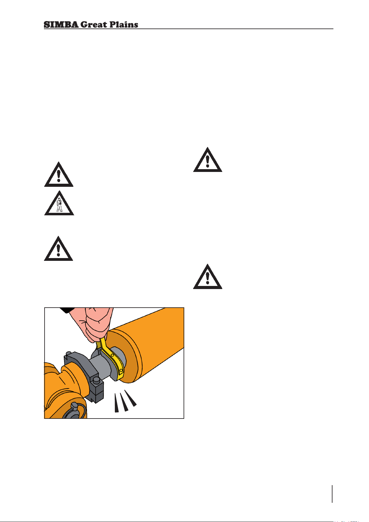
Only use appropriate aids when checking
for leaks. Repair any damage immediately.
Spurting oil can cause injuries and res!
In case of injury, contact a doctor immediately.
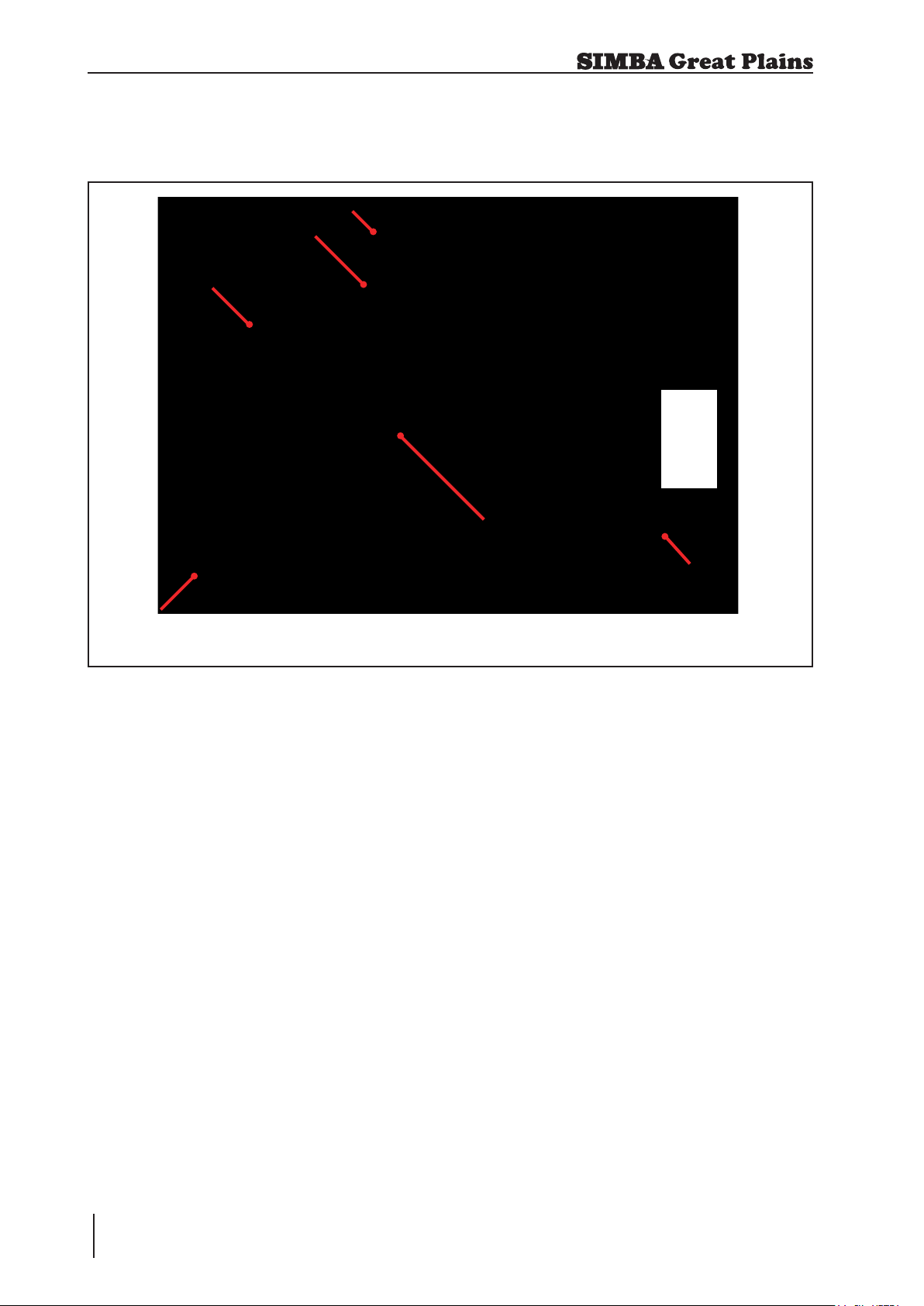
The socket and plugs for the hydraulic
connections between the tractor and the
machine should be colour-coded in order
to avoid incorrect use.
Fig. 1.01: HydraulicTaps
1.6.3 Changing Equipment
• Secure the machine to prevent it from
accidentally rolling away!
• Use suitable supports to secure any
raised frame sections suspended above
you!
• Caution! Risk of injury due to projecting
parts!
Never climb on to rotating parts
such as the roll unit. These parts
may rotate causing you to slip and
suffer serious injury!
Removing components during
mai nten ance may affect the
stability of the machine. Ensure
it is fully supported in case of
unexpected weight shifts.
1.6.4 During Operation
Ensure that the working range and the area
around the machine are clear (children!)
before operating the machine.
Always ensure adequate visibility!
Do not stand on the machine while it is in
operation!
Operators must have a valid driving licence
in order to drive on public roads. In the
operating area, the operator is responsible
for third parties.
The person in charge must:
• provide the operator with a copy of the
Operating Instructions, and
• ensure that the operator has read and
understood the instructions.
• make sure that the operator is aware of the
specic regulations relating to the machine
when driving on public roads.
1.7 Servicing &
Maintenance
Ensure that regular checks and inspections
are always carried out within the periods
required by law or specified in these
Operating Instructions.
When carrying out service and maintenance
work always:
• switch off the tractor engine and remove
the ignition key.
• wait until all the machine parts have
stopped moving.
• depressurise the hydraulic system.
Many hydraulic circuits contain lock or
overcentre valves which can retain pressure
in the lines even after depressurising the
tractor side of these circuits. If in doubt,
consult trained personnel (such as your
local Simba Great Plains Dealer) to ensure
such valves are depressurised to the correct
procedure before removing or servicing
any parts connected downstream of these
valves.
Operating Instructions
13Single Press
Page 14

1. Safety Data
Check all hydraulic lines for leaks, loose
connections, chafe marks and damage.
Remedy any deciencies immediately! Pay
particular attention to hose renewal intervals
as outlined in the specic sections which
follow. ALL hydraulic hoses have a safe
maximum working life of 6 (SIX) years from
date of installation, provided they remain in a
safe condition. Hoses which exceed 6 years
of age should be replaced, or inspected and
certied by a suitably qualied person to
have an extended life period which should
be recorded.
Pay particular attention to those items which
require specialist service tools or training
to be carried out by qualied personnel. Do
not attempt to service these items yourself!
These include items retaining pressure (e.g.
accumulator circuits), or force (e.g. spring
tines), and DD Rolls of any type.
On a new machine tighten all nuts and
bolts after 5 hours work and again after 15
hours. This also applies to parts that have
been moved or replaced. After the initial 15
hours of work a once a week check should
be sufcient depending on daily work rates.
1.8 Operating Areas
The operating areas include the drawbar,
hydraulic connections and depth adjustment
equipment as well as all operating points
requiring maintenance.
All operating areas will be specied and
described in detail in the following chapters
on servicing and maintenance.
Observe all safety regulations included in
the section dealing with Safety, and in the
subsequent sections.
Prior to performing maintenance and
servicing work, ensure that the machine
is positioned on solid, level ground and is
secured to prevent it rolling away. Do not
use any parts to climb on to the machine
unless they are specically designed for
this purpose.
Before cleaning the machine with water,
steam jets (h igh-pr e ssure c leani n g
apparatus) or other cleaning agents, cover
all openings into which, for reasons of safety
or operation, no water, steam or cleaning
agents are to penetrate (bearings, for
instance).
Lubricate all the lubricating points to force
out any trapped water.
When carrying out servicing and maintenance
work, retighten any loose screw connections.
1.9 Authorised Operators
Onl y those per sons who hav e been
authorised and instructed by the operator
may operate the machine. The operator
must be at least 16 years of age.
1.10 Protective
Equipment
For operation and maintenance, you require:
• Tight tting clothing.
• Strong protective gloves (to provide
protection against sharp-edged machine
components).
• Protective goggles (to stop dirt getting into
your eyes).
When servicing the machine take precautions
against soil, dust, seed coatings, oil or any
other hazardous substances that you might
encounter.
Single Press
14
Operating Instructions
Page 15

2. Transportation / Installation
2. Transportation and Installation
Transportation and initial installation of the
machine are described in this chapter.
2.1 Delivery
The machine is normally delivered fully
assembled.
• The machine can be lifted off with a crane
or other suitable lifting equipment.
• The machine should be hitched to a
tractor and driven off a low-loader.
2.2 Transportation
The Single Press can be transported on
public roads by hitching it up to a tractor or
on a low-loader.
2.3 Installation
When c a rryin g out ins t allat i on and
maintenance work there is a higher risk
of injury. It is important that you familiarise
yourself with the machine and read the
Operating Instructions beforehand.
Operator instruction and initial installation of
the machine are carried out by our service
technicians or authorised distributors.
The machine must not be used in any way
beforehand! The machine can only be
released for operation after instructions have
been provided by our service technicians or
authorised distributors.
• If any modules or parts have been
removed for transportation, these shall
be mounted by our service technicians/
authorised dealers before the instruction
takes place.
• It is important to observe the permitted
d i m e nsi o n s a n d w e igh t s wh e n
transporting the machine.
• If the machine is transported on a trailer
or a low-loader, it must be secured using
straps or other devices.
• Before transporting the machine on
public roads, it must be adjusted to
its transportation position and the
stipulations relating to road transportation
fullled.
• The maximum permissible speed is 25
km/h.
• Check all important screw connections!
• Lubricate all nipples and joints!
• Check all hydraulic connections and lines
for damage.
Operating Instructions
15Single Press
Page 16
2. Transportation / Installation
2.4 Hitching Up
When hitching-up the machine,
ensure that no-one is between the
tractor and the machine.
When the Single Press is parked
for extended periods of time
it should ideally be left in the
unfolded, i.e. work, position for
stability, safety and ease of access
for maintenance. However,
parking the Single Press in the
folded position (using the parking
stands provided) is acceptable in
the normal course of operation.
Tractor Oil Flow Adjustment:
As a general rule the tractor oil
flow rate should be set in the
lowest setting before starting.
This can then be increased to
allow the desired rate of operation
as applicable. This will minimise
excessive oil ow and consequent
power usage and heat generation.
2.4.1 Hitching up a Tractor to the Single Press / Preparing for Transport
1. Couple the four hydraulic hoses to
the tractor ensuring that the two wing
hoses are together and the two drawbar
cylinder hoses are together.
2. Use the hydraulics to raise or lower the
height of the shackle before hitching up
to the tractor drawbar clevis.
Do not use the tractor pick-up hitch
to attach the machine to the tractor.
This could cause damage to the
tractor and the machine.
3. Carefully operate the hydraulics to
lower the drawbar and tilt the Single
Press onto the road transport wheels.
Fully extend the drawbar cylinder.
4. Operate the hydraulics to fold the
wings.
Do not open taps while tractor
hydraulics are in oat.
The hoses in the lift circuit have
a maximum rated pressure of
415bar, and should be replaced
every 6 years. Other components
in this locking circuit have a
maximum rated pressure of at
least 350bar.
5. Ensure that the wing strap is tted to
tie the two wing sections together.
6. Ensure that parking stands are locked
in the transport position, ie. fully raised.
7. Remove the wheel chocks and stow.
Single Press
16
Operating Instructions
Page 17
2. Transportation / Installation
2.5 Folding and Unfolding
Check for exposed persons when
lowering / unfolding the machine.
Do not climb on the machine to t
or remove the transport strap, this
should be done from the ground.
2.5.1 Unfolding into the Work Position
1. Ensure that the parking stands are in
the fully raised position.
2. Remove the transport strap from the
rear wing. Stow the transport strap on
the lights as shown in Fig. 2.02.
2.5.2 Folding into the Transport Position
1. Raise the machine onto the transport
wheels.
2. Operate the hydraulics to fully fold the
wings.
3. Fit the transport strap across the pins
on the rear wing cylinders for transport
safety.
4. Close the taps on the hosemast.
5. Lower the parking stands if the Single
Press is to be unhitched from the
tractor in the folded position.
3. Open the taps on the drawbar cylinder.
Beware of sudden or uncontrolled
movements if the taps are opened
with the hydraulics in oat. Do
not open taps with the tractor
hydraulics in oat.
4. Operate the hydraulics to fully unfold
the wings.
5. Lower the machine to the ground until
the chassis is level front to rear or the
drawbar cylinders touch the depth
stops.
Fig. 2.02: Transport Strap Stowage in Work
Operating Instructions
17Single Press
Page 18

2. Transportation / Installation
2.6 Preceding Implements
Adding a preceding implement
to the Single Press will affect
the stability and handling of the
machine both in transport and
work.
2.6.1 Hitching a Disc Cultivator
Ahead of the Single Press
1. Remove the transport straps from the
disc cultivator, exercise great CARE
when extending the axle cylinder.
2. Reverse the disc cultivator up to the
Single Press drawbar ensuring that
the two drawbars are aligned allowing
a slight clearance to e nable the
machines to be coupled together.
3. Lower the disc cultivator to the ground.
4. Connect the hydraulic hoses from the
Single Press into the disc cultivator rear
outlets ensuring that the wing hoses
are together and the drawbar cylinder
hoses are together. Ensure that the
folding circuits and lift (drawbar)
circuits are coupled correctly.
8. Operate the hydraulics to lower the
rear axle and drawbar, tilting the Single
Press onto the road transport wheels.
Fully extend the drawbar cylinders.
9. Operate the hydraulics to fold the
wings.
10. Operate the hydraulics to lift the disc
cultivator into the transport position.
11. Fit the disc cultivator transport straps.
12. Fit the Single Press wing transport
strap to tie the two wing sections
together.
13. Ensure that parking stands are locked
up in their work position.
With both machines in the transport position
i.e. raised and folded, the chassis of the
disc cultivator should be slightly nose down
or horizontal even when the downward
load from the Single Press is applied to the
drawbar of the disc cultivator.
The frame may be levelled by altering the
rearward tilt of the Single Press to increase
or reduce the loading on the disc rear
drawbar.
5. Raise the Single Press drawbar above
the disc cultivator drawbar (200mm
approx.). Depth control shims may
need to be removed.
6. Raise the disc cultivator to the same
height as the Single Press drawbar
then reverse the disc cultivator to
couple the two machines together.
7. Fit the drawbar pin.
Single Press
18
Operating Instructions
2.6.2 Transporting a Single
Press Towed Behind a Disc
Cultivator
With both machines in the transport position
i.e. raised and folded, the chassis of the
disc cultivator should be slightly nose down
or horizontal even when the downward
load from the Single Press is applied to the
drawbar of the disc cultivator. The chassis
should NEVER be tail low in transport as
this will give a high negative loading on the
tractor which could lead to loss of traction
to the rear wheels.
Page 19
2. Transportation / Installation
Extreme caution must be taken when
the Single Press is transported up steep
gradients and across side slopes. Higher
drawbar loading can be achieved by
shortening the drawbar cylinder.
Prior to leaving the eld to travel on a public
highway ensure that any clods of soil are
removed from the machine to prevent them
from fouling the road.
MAXIMUM ROAD TRANSPORT SPEED 16
MPH (25 km/h).
2.6.3 Changing from Wor k
to Road Tr ansport (Single
Press Towed Behind a Disc
Cultivator)
1. Operate the hydraulics to raise the disc
and Single Press.
2.7 When Driving on the Road
When driving on the road the machine must
be converted to the transportation position.
When driving on the road, raise
the machine completely to prevent
any elements dragging on the
ground.
2.8 Parking the machine
In order to avoid damage as a result of
moisture, the machine should be parked, if
possible, indoors or under cover.
When manoeuvring the machine,
pay attention to your surroundings.
Ensure that nobody is in the
manoeuvring area (watch for
children!).
2. Operate the hydraulics to fold the
wings on both the disc cultivator and
the Single Press.
3. Fit the transp ort st raps to both
machines.
It may be necessary to shorten
the drawbar cylinder of the disc
culti vator until the c hassis is
horizontal or slightly nose down
before moving the machines.
Shortening the Single Press drawbar
cylinder will increase the loading on the rear
of the disc cultivator frame. If necessary this
can be used to level the chassis for road
transport.
• Park the machine on level and solid ground.
• With the machine raised move the
parking stands into position.
• Lower the machine onto the parking
stands ensuring that it is stable.
• Place the wheel chocks into position.
• Remove the drawbar pin and drive
forward slowly until hitch is clear of
tractor drawbar.
• Lower the drawbar to the ground.
• Switch off the tractor.
• Disconnect hydraulic lines from the
tractor.
If parking on uneven or sloping
ground unfold the machine and
lower rst to avoid instability.
Fig. 2.02: Parking Postion
19Single Press
Operating Instructions
Page 20

2. Transportation / Installation
Single Press
20
Operating Instructions
Page 21

3. Technical Data
3. Technical Data Single Press
4.2m 4.6m 5.5m 6.6m 7.6m 8.2m
Working Width 4402mm 4879mm 5812mm 6753mm 7682mm 8176mm
Transport Width 2597mm 2597mm 2597mm 2597mm 2597mm 2597mm
Transport Height 2393mm 2578mm 2935mm 3221mm 3552mm 3850mm
Length 4689mm 4835mm 5144mm 5645mm 5966mm 5901mm
Weight With DD700 2271Kg 2531Kg 2778Kg 3121Kg 3394Kg 3517Kg
Weight With Aqueel 2 1928Kg 2074Kg 2267Kg 2532Kg 2683Kg 2857Kg
Tractor Power Req.
Drawbar Load ** 322Kg 315Kg 260Kg 160Kg 57Kg 113Kg
Axle Load 1949Kg 2216Kg 2518Kg 2961Kg 3337Kg 3404Kg
Centre of Gravity *** 3597mm 3670mm 3799mm 3978mm 4122mm 4057mm
(Hp)*
* It is important to correctly match your implement to your tractor for optimum performance.
** Varies with lift, tilt and options.
*** Dimension from hitch in road transport.
85 - 105 100 -120 110 - 140 130 - 160 150 - 190 165 - 200
Operating Instructions
21Single Press
Page 22
4. Adjustment / Operation
4. Adjustment/Operation
4.1 Description
3
4
5
6
Fig. 4.01: Single Press
1. Wing Support Chain s
2. Drawbar
3. Transport Strap
4. Chocks
5. Transport Wheels
6. DD700 Roll
The Simba Great Plains Single Press is a
versatile implement designed to perform
effective consolidation. The Single Press
may be towed on its own or in tandem behind
another implement e.g. disc cultivator.
1
2
The use of the Single Press in tandem with
a disc cultivator for straw incorporation
consolidates the straw/soil mix through the
soil prole. This ensures maximum straw/soil
contact to increase the breakdown process,
minimise slug problems and to leave a rm
weatherproof nish.
It can be used in reduced tillage systems
behind a disc cultivator to incorporate stubble
or to work down ploughing on medium to
heavy soil types. Like all Simba Great Plains
machines it features the latest innovations
which combine to give an efcient, well-built
unit with unrivalled reliability.
Single Press
22
Operating Instructions
Page 23

4.2 Double Disc Roller
The standard DD700 roller is made up of
individual Double Disc (patented) Ring
segments.
The DD rings are designed to consolidate
the soil whilst cutting and crushing any clods.
Even in heavy, wet soils it can easily be
operated with minimal blockages occurring.
4. Adjustment / Operation
The DD roller carries a proportion of the
machine’s weight to ensure consolidation.
The corrugated surface left by the roller is
weatherproof both for wet or dry situations.
Fig. 4.02: Double Disc Roller
Fig. 4.03: Aqueel 2 Roller
4.4 Levelling Boards
The action of the sprung leaf type levelling
boards is to carry and drop soil to level in
front of the press rings, to rub clod against
clod for additional soil breakdown, to force
clods down into the soil prole and to present
remaining clods passing between the leaves
into the row of press rings.
The levelling boards are set using shims in
the levelling board cylinders. During work,
these cylinders should be retracted onto the
shims but can be extended to release any
soil / trash build up.
4.3 Aqueel 2 Roller
The Aqueel 2 is a rubber, specialist selfcleaning tyre which leaves a patterned
sur fac e profile consisti ng of con ica l
indentations. This is designed to combat
surface water movement and wind erosion
in the eld. The benet of Aqueeled ground
(reservoir tillage) is gained on light, easy
working soils that can slump or compact.
23Single Press
Operating Instructions
Page 24

4. Adjustment / Operation
4.5 Work Settings
In work the wing cylinders should be fully
extended. The gangs are able to oat over
any undulations on the ground due to the
accumulators in the hydraulic system.
Optimum performance has been found
to be achieved when the press roll rings
have worn away the painted nish leaving
a smooth shiny surface. When the press
roll rings are new or rusty, soil may tend to
pick up on the surface and blockage may
occur, this will reduce when the rings are
shiny again.
The Single Press should be run with the
chassis level front to rear by extending the
drawbar cylinder to the necessary position.
The cylinder should not be over extended
as this will remove the load on the rings
which could lead to reduced drive and hence
blockage of the axles.
Running the Single Press level allows the
press rings to give an even consolidation
and clod crushing action.
Running the machine significantly nose
down or raised will reduce the load on the
rear axle leading to loss of drive of the axle
and then blockage, together with a reduced
consolidation effect.
If any roll axle starts to block regularly, this
is generally an indication that the roll axle
is not tight. Failure to keep the axles tight
results in loss of drive between each pair of
rings allowing rings to turn individually on
the axle. Should this occur the axle must
be tightened immediately to prevent any
damage occurring to the axle shaft.
If the roll axles start to block regularly this
may also be an indication that the ground
conditions are too wet for the Single Press
to be effective.
It is not necessary to tilt the Single Press onto
the transport wheels during headland turns
whether the machine is used independently
or in tandem with a disc cultivator. Normally,
the Single Press should be tilted onto the
roll to a point where the rear axle wheels
are clear of ground contact.
Shims should be added to the levelling board
cylinders until the levelling boards are carrying soil. The levelling boards will need to
be set higher during 1st pass operations
especially on ploughed land where large
clods may not be able to pass under or between the sprung leaves. The boards need
to carry a certain amount of soil to effect a
levelling operation and also to give a clod
to clod crushing action.
4.6 Pitch Control
Pitch control on the Single Press is governed
by the quantity of shims tted to the drawbar
cylinder. Increasing the number of shims will
lift the front of the chassis when lowered into
the work position.
In practice it is possible to use the Single
Press on ground conditions that are unsuitable to achieve the desired effect, and it
is usually possible to operate the machine
without regular blockage under such unsuitable conditions, assuming that the axles are
tight and rings smooth.
As such, especially under wet conditions,
it is advisable to check on the cultivation
effect of the Single Press. Often the use of
the press 12 - 24 hours after a disc cultivator
(or longer following a plough) gives a far
superior surface consolidation effect.
It is not necessary to tilt the Single Press
onto the transport wheels during headland
turns whether the machine is used independently or in tandem with a disc cultivator.
Full y ext endi ng th e dra wbar
cylinder and then reversing into
the headland furrow could lead to
damage of the cylinder.
Single Press
24
Operating Instructions
Page 25
4. Adjustment / Operation
4.7 Using Shims
Before using shims to alter machine settings
ensure the machine is stationary and the
tractor is turned off with the keys out. Ensure
that all operators are clear of the machine
and that no load is being held on any existing
shims in the cylinder.
To t the shims hold them by the handle and,
using a rm action, clip them onto the rod
as shown in Fig. 4.04. They are removed by
using a nger to pull rmly on the handle.
Check the cylinders for damage
and debris before tting shims.
Only attempt to add or remove
shims using the handle. Trying to
manipulate shims using the jaws
could result in injury.
When changing machine settings
ensure both sides of the machine
mirror each other. The left hand
cylinder should contain the same
amount of shims as the right, for
example. Failure to do this could
result in damage to the machine.
4.8 Work Instructions
Driving speed
The Single Press can be driven at speeds
of up to 12 km/h.
This depends on the eld conditions (type
of soil, surface trash, etc.).
Drive more slowly if the conditions are
difcult or a rmer nish is required.
When reversing the UniPress into
corners when working headlands
ensure that the levelling boards
are fully raised and the machine
tilted onto the roll rings far enough
to allow the lower ends of the
sprung leaves to clear the ground.
Parking the Machine
In order to avoid damage as a result of
moisture, the machine should be parked, if
possible, indoors or under cover.
When manoeuvring the machine,
pay attention to your surroundings.
Ensure that nobody (children!) is
in the manoeuvring area.
Fig. 4.04: Shims
• Park the machine on level and solid ground.
• With the machine raised, lower the
parking stands into position.
• Lower the machine onto the parking
stands ensuring that it is stable.
• Place the chocks in position.
• Remove the drawbar pin and drive forward
slowly until hitch is clear of tractor drawbar.
Lower the drawbar to the ground.
• Switch off the tractor.
• Disconnect hydraulic and electric lines
from the tractor.
25Single Press
Operating Instructions
Page 26

4. Adjustment / Operation
4.9 Checks
The working qu ality de pends on the
adjustments and checks made prior to and
during work, as well as on regular servicing
and maintenance of the machine.
Before beginning work it is therefore
important to carry out any necessary
servicing and to lubricate the machine as
required.
Checks prior to, and during
work:
• Is the machine correctly hitched up and
the coupling device locked?
• Have the hydraulic and electric lines
been connected according to the colour
coding?
• Is the machine in a level operating
position and the working depth set
correctly?
• Regularly inspect the machine for
damage and signs of overloading (stress
cracks on welded joints, frame distortion)
Working Elements
• Are the double disc rings and other
cul tiva tion to ols in a service able
condition?
• Are the scrapers still operable, so that
the rolls do not jam?
Single Press
26
Operating Instructions
Page 27
5. Servicing and Maintenance
5. Servicing and
Maintenance
Follow the safety instructions for
servicing and maintenance.
Maintenance work should only
be undertaken with the machine
unfolded and lowered or on stands
with the hydraulic taps shut.
When working under the machine
ensure that the tractor handbrake
is on.
5.1 Servicing
Your machine has been designed and
constructed for maximum performance,
oper ation al efficie ncy an d ope rator
friendliness under a wide variety of operating
conditions.
5.3 Double Disc Axles
The axles on this roller are tensioned by the
main axle through the centre of the rings
and bearings.
Specialist equipment is required
for the disassembly of Double
Disc axles. Please consult your
dealer under any circumstances
that require disassembly of these
axles.
Maintenance of these rollers is limited to
daily greasing of the bearings to ush out
dirt, and regular inspection to ensure the
assemblies are tight, and scrapers are
correctly set. The axles can be tightened
provided the bearing pillar ‘U’ bolts are
loosened to avoid preloading the bearings
as they move sideways to each other.
Ensure the bearing pillars are re-tightened
to the mainframe after this.
Prior to delivery, your machine has been
checked at the factory and by your authorised
dealer to ensure that you receive a machine
in optimum condition.
To ensure trouble-free operation,
it is important that servicing and
maintenance work is performed at
the recommended intervals.
5.2 Cleaning
In order to ensure that the machine is
always in operating condition and to achieve
optimum performance, perform the cleaning
and servicing work at regular intervals.
Avoid cleaning the roll bearings with a
high-pressure hose or a direct water jet.
The housing, screwed connections and ball
bearings are not watertight.
5.4 Hydraulics
A low oil ow should be used,
i.e., tractor tickover or low ow
selected.
The wing circuit is controlled by an
overcentre valve contained within
the manifold block which positively
locks oil ow until pressurised by
the tractor. System pressure can
be retained in the circuit even
after depressurisation of the
tractor quick release couplings.
Exercise extreme care when
checking the valve or circuits,
and under no circumstances
attempt to adjust or loosen ttings
without prior reference to your
authorised Simba Great Plains
dealer, and detailed maintenance
instructions.
Operating Instructions
27Single Press
Page 28

5. Servicing and Maintenance
5.5 Preparation for
Storage
If you need to store the machine for a longer
period, observe the following points:
• Park the machine undercover if possible.
• Protect the roll against rust. If you need
to spray the implements with oil, use light
biologically degradable oils, e.g. rape oil.
Cover any rubber sections before
using oil sprays. These sections
mus t no t be oil ed. Remo ve
any traces of oil with a suitable
cleaning agent.
5.6 Operator Support
If you have a problem, please contact your
dealer. They will endeavour to solve any
problems which may occur and provide you
with support at all times.
In order to enable your dealer to deal with
problems as quickly as possible, it helps if
you can provide them with the following data.
Always state the:
• Customer Number
• Name and Address
• Machine Model
• Serial Number of Machine
• Date of Purchase and Operating Hours
• Type of Problem
5.7 Maintenance Intervals
Apart from daily m a i ntenanc e , t h e
maintenance intervals are based on the
number of operating hours and time data.
Keep a record of your operating hours to
ensure that the specified maintenance
intervals are adhered to as closely as
possible.
Never use a machine that is due for
maintenance. Ensure that all deciencies
found during regular checks are remedied
immediately.
Avoid sharp-edged and pointed
parts (disc blades, etc.) when
working on the machine.
Place the machine on suitable
s u p p o r t s w h e n w o r k i n g
underneath! Do not work under a
machine which is not supported!
On a new machine tighten all nuts and bolts
after 5 hours work and again after 15 hours.
This also applies to parts that have been
moved or replaced. After the initial 15 hours
of work a once a week check should be
sufcient depending on daily work rates.
Single Press
28
Operating Instructions
Page 29
5. Servicing and Maintenance
5.8 To Adjust the System Pressure
A low oil ow should be used,
i.e., tractor tickover or low ow
selected.
The wing circuit is controlled by an
overcentre valve which positively
locks oil ow until pressurised by
the tractor. System pressure can
be retained in the circuit even
after depressurisation of the
tractor quick release couplings.
Exercise extreme care when
checking the valve or circuits, and
under no circumstances attempt
to adjust or loosen ttings without
prior reference to your authorised
dealer, and detailed maintenance
instructions.
If the system needs adjusting, fully raise the
machine, partially fold the wings & hold them
in this position. To adjust the pressure utilise
valve A (shown in Fig. 5.01). Unscrew the
adjusting screw:
• Turning adjuster clockwise increases
pressure at wing tips.
• Turn ing adju ster anti-clo ckwi se
decreases pressure at wing tips.
Once the desired setting is achieved lock
the valve.
FRONT OF MACHINE
A
In some cases it may be necessary to
adjust the wing fold circuit pressure. Higher
pressure will cause the wing tips to dig in
causing the centre of the machine to lift it
out. Too little pressure will cause the wing
tips to lift out & the centre of the machine
to dig in. When towing another implement
behind the Single Press, the pressure may
need increasing to compensate.
In all cases, regardless of tractor make,
adjustment should start from minimum
pressure and gradually increase up to
desired pressure.
Valve adjustment should be
carried out in small increments. A
full turn of the valve will cause a
signicant change in the operation
of the machine.
Fig. 5.01: Adjusting system pressure
Only valve A should be adjusted. All
other valves are set at the factory
and should not be tampered with.
Operating Instructions
29Single Press
Page 30

5. Servicing and Maintenance
5.9 Maintenance Overview
Key
Inspect
L
Grease
Transport
Strap
Before Each Use
Levelling
Boards
L
L
10 Hours
Hubs
Hubs
Before Each Use
L
Parking
Stands
Before Each Use
Drawbar
L
Pivots
50 Hours
Aqueel 2
Bearings
DD Rolls
10 Hours
All
Hydraulics
Before Each Use
L
L
Scrapers
L
10 Hours
Lights
L
Before Each Use
Wheel Nut Torque:
270Nm
Tyres:
400/60-15.5 14 Ply
Max Tyre Pressure:
50psi / 3.5bar
Before Each Use
600 Hours
DD Axles
10 Hours
200 Hours
One pump only!
Wing
Pivots
50 Hours
Single Press
30
Operating Instructions
Page 31

5. Servicing and Maintenance
5.10 Lubricating the Machine
Please read the section below carefully
before lubricating the machine.
The machine must be lubricated regularly in
order for it to remain serviceable. Regular
lub ricatio n also contrib utes to wards
extending the service life of your machine.
The recommended lubricating intervals are
specied in “Maintenance Overview”.
After it has been washed using a highpressure hose or steam cleaned, the
machine should always be lubricated using
a grease gun.
5.11 Handling of Lubricants
Please ensure that you read the following
ins truc tion s as we ll as the releva nt
information. This also applies to any of your
employees who handle lubricants.
Hygiene
Lubricants do not present a health hazard
provided they are used for their specied
purpose.
In the case of prolonged skin contact,
lubricants, especially low-viscosity oils, may
remove the natural layer of fat contained in
the skin, resulting in dryness and possible
irritation.
It is important to take extreme care when
handling waste oil as it may contain other
irritants.
Vapours given off by cleaning agents and
oils are also a potential health hazard.
You should therefore not carry any oily cloths
around. Change soiled work clothing as
soon as possible.
Always exercise extreme care and observe
the recommended hygiene rules when
handling mineral oil products. Details of
these handling regulations can be found
in information provided by the health
authorities.
Storage and Handling
• Always store lubricants where they
cannot be accessed by children.
• Never store lubricants in open or
unlabelled containers.
Fresh Oil
• Apart from taking the usual care and
observing hygiene rules, there is no need
to take any special precautions when
handling fresh oil.
Waste Oil
• Waste o i l c an c o n t a in h a r m f ul
contaminants which may cause skin
cancer, allergies and other illnesses.
Attention!
Oil is a toxic substance. Should you swallow
any oil, do not try to vomit. Contact a doctor
immediately.
Protect your hands with barrier cream or
wear gloves to avoid contact with the skin.
Wash off any traces of oil thoroughly with
soap and hot water.
• Wash your skin thoroughly with soap
and water.
• Use special cleaning agents to clean any
dirt off your hands.
• Never wash oil residue from your skin
with petrol, diesel fuel or parafn.
• Avoid skin contact with any oily clothing.
• Do not keep any oily rags in your pockets.
• Wash soiled clothing before wearing it
again.
• Ensure that any oily footwear is disposed
of in the proper manner.
Operating Instructions
31Single Press
Page 32

5. Servicing and Maintenance
Measures in case of injury
through oil
Eyes:
Should any oil be splashed into your eyes,
rinse with water for 15 minutes. If the eye is
still irritated, contact a doctor immediately
If oil is swallowed
If oil is swallowed, it is important not to induce
vomiting. Contact a doctor immediately.
Skin irritation caused by oil
In case of prolonged skin contact, wash off
the oil with soap and water.
Oil Spills
Use either sand or a suitable granular
absorbent to soak up any spilt oil. Dispose
of the oil-contaminated absorbent in the
proper manner.
5.12 Lubricants & Hydraulic Oil
Hydraulic System
The hydraulic uid from the tractor is mixed
with the hydraulic uid from the machine.
The supplied machine hydraulic system
contains Total AZOLLA ZS 32 oil.
Lubricants
All lubricating points on the machine can be
lubricated with multigrade lubricating grease
as specied in DIN 51825 KP/2K - 40.
Oil Fires
Never use water to extinguish an oil re.
The oil will oat on the water causing the
re to spread.
Burning oil-lubricant must be extinguished
using a carbon dioxide powder or foam
extinguisher. Always wear respiratory
equipment when dealing with res of this
type.
Waste Oil Disposal
Oil-contaminated waste and used oil must
be disposed of in accordance with current
legislation.
Waste oil must be collected and disposed of
in accordance with local regulations. Never
pour used oil into unsealed sewage systems
or drains or onto the ground.
Single Press
32
Operating Instructions
Page 33

6. Faults and Remedies
6. Faults and Remedies
Single Press Troubleshooting
Fault Possible Cause Remedy
Roll axle starts to block
regularly.
Machine running too tail
low.
Roll axle is not tight. Tighten axle.
Ground conditions too wet. Wait for more suitable
Roll scrapers incorrectly
adjusted.
Lengthen work drawbar
cylinder until chassis is
horizontal or just tail low.
Increase quantity of shims
in depth stop unit.
ground conditions.
Set scrapers to run just
clear of rings and centrally
between each ring.
Operating Instructions
33Single Press
Page 34

7. Parts and Assembly
7. Parts & Assembly
General Assembly .................................................................................. 36
4.2m Single Press Complete ......................................................................................... 36
4.6m Single Press Complete ......................................................................................... 38
5.5m Single Press Complete ......................................................................................... 40
6.6m Single Press Complete ......................................................................................... 42
7.6m Single Press Complete ......................................................................................... 44
8.2m Single Press Complete ......................................................................................... 46
Drawbar Assembly......................................................................................................... 48
Chassis Assembly ......................................................................................................... 50
6 Stud Hub Assembly .................................................................................................... 52
Wings ...................................................................................................... 54
4.2m Wing Assembly LH ............................................................................................... 54
4.2m Wing Assembly RH ............................................................................................... 56
4.6m Wing Assembly LH ............................................................................................... 58
4.6m Wing Assembly RH ............................................................................................... 60
5.5m Wing Assembly LH ............................................................................................... 62
5.5m Wing Assembly RH ............................................................................................... 64
6.6m Wing Assembly LH ............................................................................................... 66
6.6m Wing Assembly RH ............................................................................................... 68
7.6m Wing Assembly LH ............................................................................................... 70
7.6m Wing Assembly RH ............................................................................................... 72
8.2m Wing Assembly LH ............................................................................................... 74
8.2m Wing Assembly RH ............................................................................................... 76
DD700 Roll Assembly ............................................................................. 78
4.2m Roll Assembly RH ................................................................................................. 78
4.2m Roll Assembly LH ................................................................................................. 80
4.6m Roll Assembly RH ................................................................................................. 82
4.6m Roll Assembly LH ................................................................................................. 84
5.5m Roll Assembly RH ................................................................................................. 86
5.5m Roll Assembly LH ................................................................................................. 88
6.6m Roll Assembly RH ................................................................................................. 90
6.6m Roll Assembly LH ................................................................................................. 92
7.6m Roll Assembly RH ................................................................................................. 94
7.6m Roll Assembly LH ................................................................................................. 96
8.2m Roll Assembly RH ................................................................................................. 98
8.2m Roll Assembly LH ............................................................................................... 100
D Axle Assembly - 5 Ring ............................................................................................ 102
DD Axle Assembly - 6 Ring.......................................................................................... 104
DD Axle Assembly - 7 Ring.......................................................................................... 106
DD Axle Assembly - 8 Ring (2 Overhung) ................................................................... 108
DD Axle Assembly - 9 Ring...........................................................................................110
DD Axle Assembly - 9 Ring (2 Overhung) ....................................................................112
DD Axle Assembly - 10 Ring (2 Overhung) ..................................................................114
Double Disc Pillar Assembly .........................................................................................116
Single Press
34
Operating Instructions
Page 35

7. Parts and Assembly
Aqueel 2 Roll Assembly ....................................................................... 118
4.2m Aqueel 2 Roll Assembly RH .................................................................................118
4.2m Aqueel 2 Roll Assembly LH ................................................................................ 120
4.6m Aqueel 2 Roll Assembly RH ................................................................................ 122
4.6m Aqueel 2 Roll Assembly LH ................................................................................ 124
5.5m Aqueel 2 Roll Assembly RH ................................................................................ 126
5.5m Aqueel 2 Roll Assembly LH ................................................................................ 128
6.6m Aqueel 2 Roll Assembly RH ................................................................................ 130
6.6m Aqueel 2 Roll Assembly LH ................................................................................ 132
7.6m Aqueel 2 Roll Assembly RH ................................................................................ 134
7.6m Aqueel 2 Roll Assembly LH ................................................................................ 136
8.2m Aqueel 2 Roll Assembly RH ................................................................................ 138
8.2m Aqueel 2 Roll Assembly LH ................................................................................ 140
Stickers ................................................................................................ 142
4.2m Single Press Stickers.......................................................................................... 142
4.6m Single Press Stickers.......................................................................................... 144
5.5m Single Press Stickers.......................................................................................... 146
6.6m Single Press Stickers.......................................................................................... 148
7.6m Single Press Stickers.......................................................................................... 150
8.2m Single Press Stickers.......................................................................................... 152
Hydraulics ............................................................................................ 154
Lift Circuit Components .............................................................................................. 154
4.2m-5.5m Wing Circuit Components.......................................................................... 156
6.6m-8.2m Wing Circuit Components.......................................................................... 158
Lift Circuit .................................................................................................................... 160
4.2m-5.5m Wing Circuit ............................................................................................... 161
6.6m-8.2m Wing Circuit ............................................................................................... 162
Operating Instructions
35Single Press
Page 36

7. Parts and Assembly
Single Press
36
Operating Instructions
Page 37

7. Parts and Assembly
A
m
m
AS3844
SINGLEPRESS 4.2m TOP LEVEL
SSEMBLY
ITEM PART NO DESCRIPTION QTY COMMENTS
1
2
3
4
5
6
7
8
9
10
11
12
13
14
15
16
17
18
19
20
21
22
23
24
25
26
27
28
29
30
31
32
33
34
35
36
37
38
39
40
41
42
43
44
45
46
47
48
49
50
AS3000 DRAWBAR ASSEMBLY - 4.2m 1
AS3830 SINGLE PRESS WING ASSEMBLY RH 4.2
AS3831 SINGLE PRESS WING ASSEMBLY LH 4.2
AS3842 SINGLEPRESS - CHASSIS ASSEMBLY 1
AS3891 4.2m RH WING DD700 WING LAYOUT 1
AS3892 4.2m LH WING DD700 WING LAYOUT 1
AS3915 SINGLE PRESS 4.2m STICKER LAYOUT 1
AS3921 SINGLEPRESS 4.2,4.6,5.5 - WING FOLD HY1
AS3924 SINGLEPRESS - LIFT HYDRAULICS 1
P17400 MANUAL - S/PRESS 2010 1
1
1
37Single Press
Operating Instructions
Page 38

7. Parts and Assembly
Single Press
38
Operating Instructions
Page 39

7. Parts and Assembly
A
m
m
AS3845
SINGLEPRESS 4.6m TOP LEVEL
SSEMBLY
ITEM PART NO DESCRIPTION QTY COMMENTS
1
2
3
4
5
6
7
8
9
10
11
12
13
14
15
16
17
18
19
20
21
22
23
24
25
26
27
28
29
30
31
32
33
34
35
36
37
38
39
40
41
42
43
44
45
46
47
48
49
50
AS3000 DRAWBAR ASSEMBLY - 4.2m 1
AS3832 SINGLE PRESS WING ASSEMBLY RH 4.6
AS3833 SINGLE PRESS WING ASSEMBLY LH 4.6
AS3842 SINGLEPRESS - CHASSIS ASSEMBLY 1
AS3893 4.6m RH WING DD700 WING LAYOUT 1
AS3894 4.6m LH WING DD700 WING LAYOUT 1
AS3916 SINGLE PRESS 4.6m STICKER LAYOUT 1
AS3921 SINGLEPRESS 4.2,4.6,5.5 - WING FOLD HY1
AS3924 SINGLEPRESS - LIFT HYDRAULICS 1
P17400 MANUAL - S/PRESS 2010 1
1
1
39Single Press
Operating Instructions
Page 40

7. Parts and Assembly
Single Press
40
Operating Instructions
Page 41

7. Parts and Assembly
A
m
m
AS3846
SINGLEPRESS 5.5m - TOP LEVEL
SSEMBLY
ITEM PART NO DESCRIPTION QTY COMMENTS
1
2
3
4
5
6
7
8
9
10
11
12
13
14
15
16
17
18
19
20
21
22
23
24
25
26
27
28
29
30
31
32
33
34
35
36
37
38
39
40
41
42
43
44
45
46
47
48
49
50
AS3000 DRAWBAR ASSEMBLY - 4.2m 1
AS3834 SINGLE PRESS WING ASSEMBLY RH 5.5
AS3835 SINGLE PRESS WING ASSEMBLY LH 5.5
AS3842 SINGLEPRESS - CHASSIS ASSEMBLY 1
AS3895 5.5m RH WING DD700 WING LAYOUT 1
AS3896 5.5m LH WING DD700 WING LAYOUT 1
AS3917 SINGLE PRESS 5.5m STICKER LAYOUT 1
AS3921 SINGLEPRESS 4.2,4.6,5.5 - WING FOLD HY1
AS3924 SINGLEPRESS - LIFT HYDRAULICS 1
P17400 MANUAL - S/PRESS 2010 1
1
1
41Single Press
Operating Instructions
Page 42

7. Parts and Assembly
Single Press
42
Operating Instructions
Page 43

7. Parts and Assembly
A
R
D
AS3847
SINGLEPRESS 6.6m - TOP LEVEL
SSEMBLY
ITEM PART NO DESCRIPTION QTY COMMENTS
1
2
3
4
5
6
7
8
9
10
11
12
13
14
15
16
17
18
19
20
21
22
23
24
25
26
27
28
29
30
31
32
33
34
35
36
37
38
39
40
41
42
43
44
45
46
47
48
49
50
AS3000 DRAWBAR ASSEMBLY - 4.2m 1
AS3836 SINGLEPRESS 6.6m - WING ASSEMBLY
AS3837 SINGLEPRESS 6.6m - WING ASSEMBLY LH1
AS3842 SINGLEPRESS - CHASSIS ASSEMBLY 1
AS3897 SINGLEPRESS 6.6m - WING RH DD700 LAY1
AS3898 SINGLEPRESS 6.6m - WING LH DD700 LAY1
AS3923 SINGLEPRESS 6.6, 7.6 & 8.2 - WING FOL
AS3924 SINGLEPRESS - LIFT HYDRAULICS 1
P17400 MANUAL - S/PRESS 2010 1
AS3918 SINGLE PRESS 6.6m STICKER LAYOUT 1
1
1
43Single Press
Operating Instructions
Page 44

7. Parts and Assembly
Single Press
44
Operating Instructions
Page 45

7. Parts and Assembly
A
R
D
AS3848
SINGLEPRESS 7.6m - TOP LEVEL
SSEMBLY
ITEM PART NO DESCRIPTION QTY COMMENTS
1
2
3
4
5
6
7
8
9
10
11
12
13
14
15
16
17
18
19
20
21
22
23
24
25
26
27
28
29
30
31
32
33
34
35
36
37
38
39
40
41
42
43
44
45
46
47
48
49
50
AS3000 DRAWBAR ASSEMBLY - 4.2m 1
AS3838 SINGLEPRESS 7.6m - WING ASSEMBLY
AS3839 SINGLEPRESS 7.6m - WING ASSEMBLY LH1
AS3842 SINGLEPRESS - CHASSIS ASSEMBLY 1
AS3899 SINGLE PRESS 7.6m RH WING DD700 WIN1
AS3900 7.6m LH WING DD700 WING LAYOUT 1
AS3919 SINGLEPRESS 7.6m - STICKER LAYOUT 1
AS3923 SINGLEPRESS 6.6, 7.6 & 8.2 - WING FOL
AS3924 SINGLEPRESS - LIFT HYDRAULICS 1
P17400 MANUAL - S/PRESS 2010 1
1
1
45Single Press
Operating Instructions
Page 46

7. Parts and Assembly
Single Press
46
Operating Instructions
Page 47

7. Parts and Assembly
A
R
D
AS3849
SINGLEPRESS 8.2m - TOP LEVEL
SSEMBLY
ITEM PART NO DESCRIPTION QTY COMMENTS
1
2
3
4
5
6
7
8
9
10
11
12
13
14
15
16
17
18
19
20
21
22
23
24
25
26
27
28
29
30
31
32
33
34
35
36
37
38
39
40
41
42
43
44
45
46
47
48
49
50
AS3000 DRAWBAR ASSEMBLY - 4.2m 1
AS3840 SINGLEPRESS 8.2m - WING ASSEMBLY
AS3841 SINGLEPRESS 8.2m - WING ASSEMBLY LH1
AS3842 SINGLEPRESS - CHASSIS ASSEMBLY 1
AS3901 SINGLEPRESS 8.2m - WING RH DD700 LAY1
AS3902 SINGLEPRESS 8.2m - WING LH DD700 LAY1
AS3920 SINGLEPRESS 8.2m - STICKER LAYOUT 1
AS3923 SINGLEPRESS 6.6, 7.6 & 8.2 - WING FOL
AS3924 SINGLEPRESS - LIFT HYDRAULICS 1
P17400 MANUAL - S/PRESS 2010 1
1
1
47Single Press
Operating Instructions
Page 48

7. Parts and Assembly
TITLE
COMPANYMASS KgCOSTCATEGORYCOMMENTSQTYMATERIALDESCRIPTIONISSUEPART NOITEM
0.57
£2.73B 1Steel - EN 8NUT CASTLE 1¾" BSW AP003691
0.50£0.63B 1EN 8 / 080M40PIN Ø25x115AP012742
KN PRODUCTS0.06£1.32B 1Steel - CrBoBUSH SPRUNG - Ø32xØ26x30BP016453
0.02£0.03B 1Steel - 43CNUT LOCK M12AP020074
0.13£0.63B 2Steel, High Strength
Low Alloy
NUT LOCK 1" P020125
FARM POWER0.05£0.14B 1 LYNCH PIN CAT 2AP024846
0.01£0.05B 1Steel - 43CPIN SPLIT Ø5.5x64AP02491
7
1
10
2
3
24
22
17
16
21
16
23 12 27
6
13
8
13
8
DAS3000
ISSUE
ASSEMBLY
FROM SERIAL NO. TO SERIAL NO.
PART NO.
ARH
22/03/2005
DATE:-
DRAWN:-
© 2007
11
4
8
18
15
8
25
25
9
5
20
9
14
9
5
19
9
SIMBA
UNIPRESS
MACHINE:-
14
Single Press
48
Operating Instructions
26
DESCRIPTION:-
DRAWBAR ASSEMBLY - 4.2m
Page 49

7. Parts and Assembly
AS3000
ITEM PART NO DESCRIPTION QTY COMMENTS
1
2
3
4
5
6
7
8
9
10
11
12
13
14
15
16
17
18
19
20
21
22
23
24
25
26
27
28
29
30
31
32
33
34
35
36
37
38
39
40
41
42
43
44
45
46
47
48
49
50
P00369 NUT CASTLE 1¾" BSW 1
P01274 PIN Ø25x115 1
P01645 BUSH SPRUNG - Ø32xØ26x30 1
P02007 NUT LOCK M12 1
P02012 NUT LOCK 1" 2
P02484 LYNCH PIN CAT 2 1
P02491 PIN SPLIT Ø5.5x64 1
P02600 WASHER FLAT M10 4
P02604 WASHER FLAT M24 Ø50 4
P02623 WASHER FLAT M45 1
P03088 BOLT M12x60 GR. 8.8 1
P05400 WASHER FLAT M6 3
P05534 NUT LOCK M10 2
P08548 BOLT 1" UNFx7" GR. V 2
P09092 HOSE STOWAGE PLATE 1
P09112 CLAMP ½" BSP PAIR 4
P09113 CLAMP - TOP PLATE 2
P09252 HOSE MAST 1
P09516 HITCH - FRONT 1
P09686 DRAWBAR - UNIPRESS 4.2m 1
P10049 BOLT M8x25 STAUFF STACK 2
P10278 BOLT M8x45 GR. 8.8 2
P10293 BOLT M6x20 GR. 8.8 3
P10727 BOLT 1 3/4" BSWx280 1
P12690 BOLT M10x30 GR. 8.8 2
P16360 CAT3-CAT2 BUSH INSERT 1
P17815 MANUAL HOLDER - COMPLETE 1
DRAWBAR ASSEMBLY - 4.2m
Operating Instructions
49Single Press
Page 50

7. Parts and Assembly
Single Press
50
Operating Instructions
Page 51

7. Parts and Assembly
A
AS3842
SINGLEPRESS - CHASSIS
SSEMBLY
ITEM PART NO DESCRIPTION QTY COMMENTS
1
2
3
4
5
6
7
8
9
10
11
12
13
14
15
16
17
18
19
20
21
22
23
24
25
26
27
28
29
30
31
32
33
34
35
36
37
38
39
40
41
42
43
44
45
46
47
48
49
50
P00071 NIPPLE - GREASE 1
P00874 BOLT M20x70 GR. 8.8 4
P01274 PIN Ø25x115 5
P01587 CHAIN 50x25xØ16 STATE LENGTH 2
P01645 BUSH SPRUNG - Ø32xØ26x30 5
P01845 TOPLINK CAT 1 2
P02007 NUT LOCK M12 2
P02009 NUT LOCK M20 4
P02310 5/8 Screw Pin Shackle 2
P02484 LYNCH PIN CAT 2 5
P02601 WASHER FLAT M12 2
P02603 WASHER FLAT M20 8
P02789 BOLT M8x20 GR. 8.8 8
P03089 BOLT M12x65 GR. 8.8 2
P04128 WHEEL ASSY 400/60x15.5 6 STUD 2
P04233 SPANNER - M60 2
P04753 BOLT M8x60 GR. 8.8 2
P05122 SERIAL PLATE 1
P05213 NUT LOCK M8 TYPE T 2
P05361 RATCHET STRAP 1
P05535 WASHER FLAT M8 12
P05796 REFLECTOR - RED 2
P05797 LIGHT UNIT 2
P05820 JUNCTION BOX 1
P06337 BULB INDICATOR LLB 335 2
P06338 BULB STOP/TAIL LIGHT LLB 380 2
P06400 BOLT M4x15 GR. 8.8 4
P06402 WASHER FLAT M4 4
P07543 PLASTIC END CAP 40x40 2
P07768 LIGHT MOUNTING BRACKET 2
P08802 SHIM KIT 7 PIECE 1
P08817 WASHER SPRING M8 8
P11630 BUSH Ø65xØ45x5 2
P13033 HUB ASSEMBLY 6 STUD COMPLETE 2
P13150 MAINFRAME - AQUEELPRESS 1
P14032 RIVET Ø5x16 2
P16552 NUT LOCK M4 4
P17386 CHOCK TYPE UK46St 2
P17387 CHOCK CARRIER UK46ST 2
51Single Press
Operating Instructions
Page 52

7. Parts and Assembly
Single Press
52
Operating Instructions
Page 53

7. Parts and Assembly
AS1577
HUB ASSEMBLY 6 STUD
COMPLETE
ITEM PART NO DESCRIPTION QTY COMMENTS
1
2
3
4
5
6
7
8
9
10
11
12
13
14
15
16
17
18
19
20
21
22
23
24
25
26
27
28
29
30
31
32
33
34
35
36
37
38
39
40
41
42
43
44
45
46
47
48
49
50
P12900 NIPPLE - GREASE M8 1
P13033 HUB ASSEMBLY 6 STUD COMPLETE 1
P13034 HUB 6 STUD 1
P13036 BEARING 30213 Ø120xØ65 1
P13037 GREASE SEAL Ø120xØ67 1
P13039 BEARING 32210 Ø90xØ50 1
P13040 SPRING CLIP Ø4x67 1
P13041 NUT CASTLE M39x1.5 1
P13042 DUST CAP 6 STUD 1
P13043 WHEEL STUD M18x1.5x50 10.9 6
P13044 WHEEL NUT M18x1.5 6
P13189 HUB NUT AND LOCK CLIP 1
P13325 SEAL SHIELD Ø150xØ67 1
P17703 SEAL SHIELD Ø136xØ67 1
ITEMS 1 + 3-14
KIT PART ONLY SEE ITEM 12
KIT PART ONLY SEE ITEM 12
KIT ITEMS 7 + 8
USE BEFORE 06/2010
USE AFTER 06/2010
Operating Instructions
53Single Press
Page 54

7. Parts and Assembly
Single Press
54
Operating Instructions
Page 55

7. Parts and Assembly
AS3830
SINGLE PRESS WING ASSEMBLY
RH 4.2m
ITEM PART NO DESCRIPTION QTY COMMENTS
1
2
3
4
5
6
7
8
9
10
11
12
13
14
15
16
17
18
19
20
21
22
23
24
25
26
27
28
29
30
31
32
33
34
35
36
37
38
39
40
41
42
43
44
45
46
47
48
49
50
P00071 NIPPLE - GREASE 2
P01274 PIN Ø25x115 1
P01597 BOLT M36x240 GRS GR. 8.8 2
P01645 BUSH SPRUNG - Ø32xØ26x30 1
P01704 BOLT M16x50 GR8.8 2
P02008 NUT LOCK M16 'TYPE T' 2
P02012 NUT LOCK M36 2
P02310 5/8 Screw Pin Shackle 1
P02484 LYNCH PIN CAT 2 2
P02541 WASHER FLAT M36 4
P02602 WASHER FLAT M16 4
P06155 RATCHET STRAP MOUNT 1
P09714 PARKING STAND STOP 1
P09730 PIN - PARKING STAND 1
P10284 WING RH 4.2m 1
P10492 PARKING STAND 1
Operating Instructions
55Single Press
Page 56

7. Parts and Assembly
Single Press
56
Operating Instructions
Page 57

7. Parts and Assembly
AS3831
SINGLE PRESS WING ASSEMBLY
LH 4.2m
ITEM PART NO DESCRIPTION QTY COMMENTS
1
2
3
4
5
6
7
8
9
10
11
12
13
14
15
16
17
18
19
20
21
22
23
24
25
26
27
28
29
30
31
32
33
34
35
36
37
38
39
40
41
42
43
44
45
46
47
48
49
50
P00071 NIPPLE - GREASE 2
P01274 PIN Ø25x115 1
P01597 BOLT M36x240 GRS GR. 8.8 2
P01645 BUSH SPRUNG - Ø32xØ26x30 1
P01704 BOLT M16x50 GR8.8 2
P02008 NUT LOCK M16 'TYPE T' 2
P02012 NUT LOCK M36 2
P02310 5/8 Screw Pin Shackle 1
P02484 LYNCH PIN CAT 2 2
P02541 WASHER FLAT M36 4
P02602 WASHER FLAT M16 4
P06155 RATCHET STRAP MOUNT 1
P09714 PARKING STAND STOP 1
P09730 PIN - PARKING STAND 1
P10285 WING LH 4.2m 1
P10492 PARKING STAND 1
Operating Instructions
57Single Press
Page 58

7. Parts and Assembly
Single Press
58
Operating Instructions
Page 59

7. Parts and Assembly
AS3832
SINGLE PRESS WING ASSEMBLY
RH 4.6m
ITEM PART NO DESCRIPTION QTY COMMENTS
1
2
3
4
5
6
7
8
9
10
11
12
13
14
15
16
17
18
19
20
21
22
23
24
25
26
27
28
29
30
31
32
33
34
35
36
37
38
39
40
41
42
43
44
45
46
47
48
49
50
P00071 NIPPLE - GREASE 2
P01274 PIN Ø25x115 1
P01597 BOLT M36x240 GRS GR. 8.8 2
P01645 BUSH SPRUNG - Ø32xØ26x30 1
P01704 BOLT M16x50 GR8.8 2
P02008 NUT LOCK M16 'TYPE T' 2
P02012 NUT LOCK M36 2
P02310 5/8 Screw Pin Shackle 1
P02484 LYNCH PIN CAT 2 2
P02541 WASHER FLAT M36 4
P02602 WASHER FLAT M16 4
P06155 RATCHET STRAP MOUNT 1
P09714 PARKING STAND STOP 1
P09730 PIN - PARKING STAND 1
P10425 WING RH 4.6m 1
P10492 PARKING STAND 1
Operating Instructions
59Single Press
Page 60

7. Parts and Assembly
Single Press
60
Operating Instructions
Page 61

7. Parts and Assembly
AS3833
SINGLE PRESS WING ASSEMBLY
LH 4.6m
ITEM PART NO DESCRIPTION QTY COMMENTS
1
2
3
4
5
6
7
8
9
10
11
12
13
14
15
16
17
18
19
20
21
22
23
24
25
26
27
28
29
30
31
32
33
34
35
36
37
38
39
40
41
42
43
44
45
46
47
48
49
50
P00071 NIPPLE - GREASE 2
P01274 PIN Ø25x115 1
P01597 BOLT M36x240 GRS GR. 8.8 2
P01645 BUSH SPRUNG - Ø32xØ26x30 1
P01704 BOLT M16x50 GR8.8 2
P02008 NUT LOCK M16 'TYPE T' 2
P02012 NUT LOCK M36 2
P02310 5/8 Screw Pin Shackle 1
P02484 LYNCH PIN CAT 2 2
P02541 WASHER FLAT M36 4
P02602 WASHER FLAT M16 4
P06155 RATCHET STRAP MOUNT 1
P09714 PARKING STAND STOP 1
P09730 PIN - PARKING STAND 1
P10426 WING LH 4.6m 1
P10492 PARKING STAND 1
Operating Instructions
61Single Press
Page 62

7. Parts and Assembly
Single Press
62
Operating Instructions
Page 63

7. Parts and Assembly
AS3834
SINGLE PRESS WING ASSEMBLY
RH 5.5m
ITEM PART NO DESCRIPTION QTY COMMENTS
1
2
3
4
5
6
7
8
9
10
11
12
13
14
15
16
17
18
19
20
21
22
23
24
25
26
27
28
29
30
31
32
33
34
35
36
37
38
39
40
41
42
43
44
45
46
47
48
49
50
P00071 NIPPLE - GREASE 2
P01274 PIN Ø25x115 1
P01597 BOLT M36x240 GRS GR. 8.8 2
P01645 BUSH SPRUNG - Ø32xØ26x30 1
P01704 BOLT M16x50 GR8.8 2
P02008 NUT LOCK M16 'TYPE T' 2
P02012 NUT LOCK M36 2
P02310 5/8 Screw Pin Shackle 1
P02484 LYNCH PIN CAT 2 2
P02541 WASHER FLAT M36 4
P02602 WASHER FLAT M16 4
P06155 RATCHET STRAP MOUNT 1
P09714 PARKING STAND STOP 1
P09730 PIN - PARKING STAND 1
P10427 WING RH 5.5m 1
P10492 PARKING STAND 1
Operating Instructions
63Single Press
Page 64

7. Parts and Assembly
Single Press
64
Operating Instructions
Page 65

7. Parts and Assembly
AS3835
SINGLE PRESS WING ASSEMBLY
LH 5.5m
ITEM PART NO DESCRIPTION QTY COMMENTS
1
2
3
4
5
6
7
8
9
10
11
12
13
14
15
16
17
18
19
20
21
22
23
24
25
26
27
28
29
30
31
32
33
34
35
36
37
38
39
40
41
42
43
44
45
46
47
48
49
50
P00071 NIPPLE - GREASE 2
P01274 PIN Ø25x115 1
P01597 BOLT M36x240 GRS GR. 8.8 2
P01645 BUSH SPRUNG - Ø32xØ26x30 1
P01704 BOLT M16x50 GR8.8 2
P02008 NUT LOCK M16 'TYPE T' 2
P02012 NUT LOCK M36 2
P02310 5/8 Screw Pin Shackle 1
P02484 LYNCH PIN CAT 2 2
P02541 WASHER FLAT M36 4
P02602 WASHER FLAT M16 4
P06155 RATCHET STRAP MOUNT 1
P09714 PARKING STAND STOP 1
P09730 PIN - PARKING STAND 1
P10428 WING LH 5.5m 1
P10492 PARKING STAND 1
Operating Instructions
65Single Press
Page 66

7. Parts and Assembly
Single Press
66
Operating Instructions
Page 67

7. Parts and Assembly
AS3836
SINGLEPRESS 6.6m - WING
ASSEMBLY RH
ITEM PART NO DESCRIPTION QTY COMMENTS
1
2
3
4
5
6
7
8
9
10
11
12
13
14
15
16
17
18
19
20
21
22
23
24
25
26
27
28
29
30
31
32
33
34
35
36
37
38
39
40
41
42
43
44
45
46
47
48
49
50
P00071 NIPPLE - GREASE 2
P01274 PIN Ø25x115 2
P01597 BOLT M36x240 GRS GR. 8.8 2
P01645 BUSH SPRUNG - Ø32xØ26x30 2
P01704 BOLT M16x50 GR8.8 2
P02008 NUT LOCK M16 'TYPE T' 2
P02012 NUT LOCK M36 2
P02310 5/8 Screw Pin Shackle 1
P02484 LYNCH PIN CAT 2 3
P02541 WASHER FLAT M36 4
P02602 WASHER FLAT M16 4
P06155 RATCHET STRAP MOUNT 1
P09714 PARKING STAND STOP 1
P09730 PIN - PARKING STAND 1
P10431 AQUEEL PRESS RH WING 1
P10492 PARKING STAND 1
Operating Instructions
67Single Press
Page 68

7. Parts and Assembly
Single Press
68
Operating Instructions
Page 69

7. Parts and Assembly
AS3837
SINGLEPRESS 6.6m - WING
FRAME ASSEMBLY LH
ITEM PART NO DESCRIPTION QTY COMMENTS
1
2
3
4
5
6
7
8
9
10
11
12
13
14
15
16
17
18
19
20
21
22
23
24
25
26
27
28
29
30
31
32
33
34
35
36
37
38
39
40
41
42
43
44
45
46
47
48
49
50
P00071 NIPPLE - GREASE 2
P01274 PIN Ø25x115 2
P01597 BOLT M36x240 GRS GR. 8.8 2
P01645 BUSH SPRUNG - Ø32xØ26x30 2
P01704 BOLT M16x50 GR8.8 2
P02008 NUT LOCK M16 'TYPE T' 2
P02012 NUT LOCK M36 2
P02310 5/8 Screw Pin Shackle 1
P02484 LYNCH PIN CAT 2 3
P02541 WASHER FLAT M36 4
P02602 WASHER FLAT M16 4
P06155 RATCHET STRAP MOUNT 1
P09714 PARKING STAND STOP 1
P09730 PIN - PARKING STAND 1
P10432 AQUEEL PRESS LH WING 1
P10492 PARKING STAND 1
Operating Instructions
69Single Press
Page 70

7. Parts and Assembly
Single Press
70
Operating Instructions
Page 71

7. Parts and Assembly
AS3838
SINGLE PRESS WING ASSEMBLY
LH 7.6m
ITEM PART NO DESCRIPTION QTY COMMENTS
1
2
3
4
5
6
7
8
9
10
11
12
13
14
15
16
17
18
19
20
21
22
23
24
25
26
27
28
29
30
31
32
33
34
35
36
37
38
39
40
41
42
43
44
45
46
47
48
49
50
P00071 NIPPLE - GREASE 2
P01274 PIN Ø25x115 2
P01597 BOLT M36x240 GRS GR. 8.8 2
P01645 BUSH SPRUNG - Ø32xØ26x30 2
P01704 BOLT M16x50 GR8.8 2
P02008 NUT LOCK M16 'TYPE T' 2
P02012 NUT LOCK M36 2
P02310 5/8 Screw Pin Shackle 1
P02484 LYNCH PIN CAT 2 3
P02541 WASHER FLAT M36 4
P02602 WASHER FLAT M16 4
P06155 RATCHET STRAP MOUNT 1
P09714 PARKING STAND STOP 1
P09730 PIN - PARKING STAND 1
P10433 WING RH 7.6m 1
P10492 PARKING STAND 1
Operating Instructions
71Single Press
Page 72

7. Parts and Assembly
Single Press
72
Operating Instructions
Page 73

7. Parts and Assembly
AS3839
SINGLE PRESS WING ASSEMBLY
RH 7.6m
ITEM PART NO DESCRIPTION QTY COMMENTS
1
2
3
4
5
6
7
8
9
10
11
12
13
14
15
16
17
18
19
20
21
22
23
24
25
26
27
28
29
30
31
32
33
34
35
36
37
38
39
40
41
42
43
44
45
46
47
48
49
50
P00071 NIPPLE - GREASE 2
P01274 PIN Ø25x115 2
P01597 BOLT M36x240 GRS GR. 8.8 2
P01645 BUSH SPRUNG - Ø32xØ26x30 2
P01704 BOLT M16x50 GR8.8 2
P02008 NUT LOCK M16 'TYPE T' 2
P02012 NUT LOCK M36 2
P02310 5/8 Screw Pin Shackle 1
P02484 LYNCH PIN CAT 2 3
P02541 WASHER FLAT M36 4
P02602 WASHER FLAT M16 4
P06155 RATCHET STRAP MOUNT 1
P09714 PARKING STAND STOP 1
P09730 PIN - PARKING STAND 1
P10434 WING LH 7.6m 1
P10492 PARKING STAND 1
Operating Instructions
73Single Press
Page 74

7. Parts and Assembly
Single Press
74
Operating Instructions
Page 75

7. Parts and Assembly
AS3840
SINGLEPRESS 8.2m - WING
ASSEMBLY RH
ITEM PART NO DESCRIPTION QTY COMMENTS
1
2
3
4
5
6
7
8
9
10
11
12
13
14
15
16
17
18
19
20
21
22
23
24
25
26
27
28
29
30
31
32
33
34
35
36
37
38
39
40
41
42
43
44
45
46
47
48
49
50
P00071 NIPPLE - GREASE 2
P01274 PIN Ø25x115 2
P01597 BOLT M36x240 GRS GR. 8.8 2
P01645 BUSH SPRUNG - Ø32xØ26x30 2
P01704 BOLT M16x50 GR8.8 2
P02008 NUT LOCK M16 'TYPE T' 2
P02012 NUT LOCK M36 2
P02310 5/8 Screw Pin Shackle 1
P02484 LYNCH PIN CAT 2 3
P02541 WASHER FLAT M36 4
P02602 WASHER FLAT M16 4
P06155 RATCHET STRAP MOUNT 1
P09714 PARKING STAND STOP 1
P09730 PIN - PARKING STAND 1
P10492 PARKING STAND 1
P11224 WING RH 8.2m 1
Operating Instructions
75Single Press
Page 76

7. Parts and Assembly
Single Press
76
Operating Instructions
Page 77

7. Parts and Assembly
AS3841
SINGLEPRESS 8.2m - WING
FRAME ASSEMBLY LH
ITEM PART NO DESCRIPTION QTY COMMENTS
1
2
3
4
5
6
7
8
9
10
11
12
13
14
15
16
17
18
19
20
21
22
23
24
25
26
27
28
29
30
31
32
33
34
35
36
37
38
39
40
41
42
43
44
45
46
47
48
49
50
P00071 NIPPLE - GREASE 2
P01274 PIN Ø25x115 2
P01597 BOLT M36x240 GRS GR. 8.8 2
P01645 BUSH SPRUNG - Ø32xØ26x30 2
P01704 BOLT M16x50 GR8.8 2
P02008 NUT LOCK M16 'TYPE T' 2
P02012 NUT LOCK M36 2
P02310 5/8 Screw Pin Shackle 1
P02484 LYNCH PIN CAT 2 3
P02541 WASHER FLAT M36 4
P02602 WASHER FLAT M16 4
P06155 RATCHET STRAP MOUNT 1
P09714 PARKING STAND STOP 1
P09730 PIN - PARKING STAND 1
P10492 PARKING STAND 1
P11225 WING LH 8.2m 1
Operating Instructions
77Single Press
Page 78

7. Parts and Assembly
Single Press
78
Operating Instructions
Page 79

7. Parts and Assembly
AS3891
4.2m RH WING DD700 WING
LAYOUT
ITEM PART NO DESCRIPTION QTY COMMENTS
1
2
3
4
5
6
7
8
9
10
11
12
13
14
15
16
17
18
19
20
21
22
23
24
25
26
27
28
29
30
31
32
33
34
35
36
37
38
39
40
41
42
43
44
45
46
47
48
49
50
AS1208 AXLE ASSEMBLY - DD700 9 RINGS 1
P02008 NUT LOCK M16 'TYPE T' 12
P02602 WASHER FLAT M16 12
P04179 WASHER FLAT M12 Ø38 16
P06802 BOLT U M16 GR8.8 190x117 6
P08923 DECAL - DD SMALL 1
P09558 SCRAPER PLATE 6
P09559 SCRAPER STEM RH 4
P09560 SCRAPER STEM LH 2
P10029 SCRAPER 1 1/2 2
P10870 BOLT M12x30 GR. 8.8 16
P11694 DECAL - GREASE 10 HOURS 2
P12558 DECAL - AXLE TENSION 1
Operating Instructions
79Single Press
Page 80

7. Parts and Assembly
Single Press
80
Operating Instructions
Page 81

7. Parts and Assembly
AS3892
4.2m WING LH DD700 WING
LAYOUT
ITEM PART NO DESCRIPTION QTY COMMENTS
1
2
3
4
5
6
7
8
9
10
11
12
13
14
15
16
17
18
19
20
21
22
23
24
25
26
27
28
29
30
31
32
33
34
35
36
37
38
39
40
41
42
43
44
45
46
47
48
49
50
AS0894
AXLE ASSEMBLY - DD700 10 RINGS 2 OVERHUNG
P02008 NUT LOCK M16 'TYPE T' 14
P02602 WASHER FLAT M16 14
P04179 WASHER FLAT M12 Ø38 18
P06802 BOLT U M16 GR8.8 190x117 7
P08923 DECAL - DD SMALL 1
P09558 SCRAPER PLATE 7
P09559 SCRAPER STEM RH 1
P09560 SCRAPER STEM LH 6
P10029 SCRAPER 1 1/2 2
P10870 BOLT M12x30 GR. 8.8 18
P11694 DECAL - GREASE 10 HOURS 2
P12558 DECAL - AXLE TENSION 1
1
Operating Instructions
81Single Press
Page 82

7. Parts and Assembly
Single Press
82
Operating Instructions
Page 83

7. Parts and Assembly
AS3893
4.6M RH WING DD700 WING
LAYOUT
ITEM PART NO DESCRIPTION QTY COMMENTS
1
2
3
4
5
6
7
8
9
10
11
12
13
14
15
16
17
18
19
20
21
22
23
24
25
26
27
28
29
30
31
32
33
34
35
36
37
38
39
40
41
42
43
44
45
46
47
48
49
50
AS0775 AXLE ASSEMBLY - DD700 5 RINGS 2
P02008 NUT LOCK M16 'TYPE T' 10
P02602 WASHER FLAT M16 10
P02603 WASHER FLAT M20 2
P04179 WASHER FLAT M12 Ø38 18
P06802 BOLT U M16 GR8.8 190x117 5
P08923 DECAL - DD SMALL 1
P09558 SCRAPER PLATE 7
P09559 SCRAPER STEM RH 5
P10029 SCRAPER 1 1/2 2
P10870 BOLT M12x30 GR. 8.8 18
P11694 DECAL - GREASE 10 HOURS 4
P12558 DECAL - AXLE TENSION 1
P12777 BOLT M20x180 GR12.9 2
Operating Instructions
83Single Press
Page 84

7. Parts and Assembly
Single Press
84
Operating Instructions
Page 85

7. Parts and Assembly
AS3894
4.6m WING DD700 WING
LAYOUT
ITEM PART NO DESCRIPTION QTY COMMENTS
1
2
3
4
5
6
7
8
9
10
11
12
13
14
15
16
17
18
19
20
21
22
23
24
25
26
27
28
29
30
31
32
33
34
35
36
37
38
39
40
41
42
43
44
45
46
47
48
49
50
AS0775 AXLE ASSEMBLY - DD700 5 RINGS 1
AS0903
AXLE ASSEMBLY - DD700 6 RINGS 2 OVERHUNG
P02008 NUT LOCK M16 'TYPE T' 12
P02602 WASHER FLAT M16 12
P02603 WASHER FLAT M20 2
P04179 WASHER FLAT M12 Ø38 20
P06802 BOLT U M16 GR8.8 190x117 6
P08923 DECAL - DD SMALL 1
P09558 SCRAPER PLATE 8
P09560 SCRAPER STEM LH 6
P10029 SCRAPER 1 1/2 2
P10870 BOLT M12x30 GR. 8.8 20
P11694 DECAL - GREASE 10 HOURS 4
P12558 DECAL - AXLE TENSION 1
P12777 BOLT M20x180 GR12.9 2
1
Operating Instructions
85Single Press
Page 86

7. Parts and Assembly
Single Press
86
Operating Instructions
Page 87

7. Parts and Assembly
AS3895
5.5m RH WING DD700 WING
LAYOUT
ITEM PART NO DESCRIPTION QTY COMMENTS
1
2
3
4
5
6
7
8
9
10
11
12
13
14
15
16
17
18
19
20
21
22
23
24
25
26
27
28
29
30
31
32
33
34
35
36
37
38
39
40
41
42
43
44
45
46
47
48
49
50
AS0776 AXLE ASSEMBLY - DD700 6 RINGS 2
P02008 NUT LOCK M16 'TYPE T' 14
P02602 WASHER FLAT M16 14
P04179 WASHER FLAT M12 Ø38 22
P06802 BOLT U M16 GR8.8 190x117 7
P08923 DECAL - DD SMALL 1
P09558 SCRAPER PLATE 9
P09559 SCRAPER STEM RH 5
P09560 SCRAPER STEM LH 2
P10029 SCRAPER 1 1/2 2
P10870 BOLT M12x30 GR. 8.8 22
P11694 DECAL - GREASE 10 HOURS 4
P12558 DECAL - AXLE TENSION 1
Operating Instructions
87Single Press
Page 88

7. Parts and Assembly
Single Press
88
Operating Instructions
Page 89

7. Parts and Assembly
AS3896
5.5m LH WING DD700 WING
LAYOUT
ITEM PART NO DESCRIPTION QTY COMMENTS
1
2
3
4
5
6
7
8
9
10
11
12
13
14
15
16
17
18
19
20
21
22
23
24
25
26
27
28
29
30
31
32
33
34
35
36
37
38
39
40
41
42
43
44
45
46
47
48
49
50
AS0776 AXLE ASSEMBLY - DD700 6 RINGS 1
AS2441
AXLE ASSEMBLY - DD700 7 RINGS 3 OVERHUNG
P02008 NUT LOCK M16 'TYPE T' 16
P02602 WASHER FLAT M16 16
P04179 WASHER FLAT M12 Ø38 24
P06802 BOLT U M16 GR8.8 190x117 8
P08923 DECAL - DD SMALL 1
P09558 SCRAPER PLATE 10
P09559 SCRAPER STEM RH 4
P09560 SCRAPER STEM LH 4
P10029 SCRAPER 1 1/2 2
P10870 BOLT M12x30 GR. 8.8 24
P11694 DECAL - GREASE 10 HOURS 4
P12558 DECAL - AXLE TENSION 1
1
Operating Instructions
89Single Press
Page 90

7. Parts and Assembly
TITLE
COMPANYMASS KgCOSTCATEGORYCOMMENTSQTYMATERIALDESCRIPTIONISSUEPART NOITEM
384.85 A 2 AXLE ASSEMBLY - DD700 7
RINGS
AAS06431
0.04
£0.06BDIN 98518Steel, High Strength
Low Alloy
NUT LOCK M16 'TYPE T'AP020082
0.02£0.03B 16Steel, High Strength
Low Alloy
WASHER FLAT M16AP026023
0.02£0.03B 2Steel, High Strength
WASHER FLAT M20AP026034
BAS3897
ISSUE
ASSEMBLY
10
8
2
3
9
A
6
18
2
11
5
11
17
5
15
16
16
14
11
5
1
5
11
8
FROM SERIAL NO. TO SERIAL NO.
PART NO.
AGD
20/11/2009
DATE:-
DRAWN:-
© 2009
SIMBA
MACHINE:-
1
12
B
1
13
7
4
A
DESCRIPTION:-
SINGLEPRESS 6.6m - WING RH DD700 LAYOUT
Single Press
90
Operating Instructions
Page 91

7. Parts and Assembly
AS3897
SINGLE PRESS 6.6m - WING RH DD700
LAYOUT
ITEM PART NO DESCRIPTION QTY COMMENTS
1
2
3
4
5
6
7
8
9
10
11
12
13
14
15
16
17
18
19
20
21
22
23
24
25
26
27
28
29
30
31
32
33
34
35
36
37
38
39
40
41
42
43
44
45
46
47
48
49
50
AS0643 AXLE ASSEMBLY - DD700 7 RINGS 2
P02008 NUT LOCK M16 'TYPE T' 18
P02602 WASHER FLAT M16 16
P02603 WASHER FLAT M20 2
P04179 WASHER FLAT M12 Ø38 26
P06802 BOLT U M16 GR8.8 190x117 8
P08923 DECAL - DD SMALL 1
P09558 SCRAPER PLATE 10
P09559 SCRAPER STEM RH 8
P10029 SCRAPER 1 1/2 2
P10870 BOLT M12x30 GR. 8.8 25
P11694 DECAL - GREASE 10 HOURS 4
P12558 DECAL - AXLE TENSION 1
P12777 BOLT M20x180 GR12.9 2
P18644 SCRAPER PLATE 1
P18645 SCRAPER STEM RH CUTOUT 1
P18649 BOLT M16x200 GR 8.8 CSK 2
P18650 CLAMP PLATE 100x M16 1
Operating Instructions
91Single Press
Page 92

7. Parts and Assembly
TITLE
COMPANYMASS KgCOSTCATEGORYCOMMENTSQTYMATERIALDESCRIPTIONISSUEPART NOITEM
384.85 A 1 AXLE ASSEMBLY - DD700 7
RINGS
AAS06431
432.59 A 1 AXLE ASSEMBLY - DD700 8
RINGS 2 OVERHUNG
BAS08962
0.04
£0.06
BDIN 98520
Steel, High Strength
Low Alloy
NUT LOCK M16 'TYPE T'
AP020083
BAS3898
ISSUE
ASSEMBLY
12
6
9
2
15
6
17
16
18
3
B
13
5
12
19
12
6
9
3
4
10
FROM SERIAL NO. TO SERIAL NO.
PART NO.
AGD
20/11/2009
DATE:-
DRAWN:-
© 2009
SIMBA
12
6
SINGLE PRESS
MACHINE:-
11
1
A
13
Single Press
92
Operating Instructions
7
A
8
14
DESCRIPTION:-
SINGLEPRESS 6.6m - WING LH DD700 LAYOUT
Page 93

7. Parts and Assembly
A
AS3898
SINGLE PRESS 6.6m - WING LH DD700
LAYOUT
ITEM PART NO DESCRIPTION QTY COMMENTS
1
2
3
4
5
6
7
8
9
10
11
12
13
14
15
16
17
18
19
20
21
22
23
24
25
26
27
28
29
30
31
32
33
34
35
36
37
38
39
40
41
42
43
44
45
46
47
48
49
50
AS0643 AXLE ASSEMBLY - DD700 7 RINGS 1
AS0896
XLE ASSEMBLY - DD700 8 RINGS 2 OVER1
P02008 NUT LOCK M16 'TYPE T' 20
P02602 WASHER FLAT M16 18
P02603 WASHER FLAT M20 2
P04179 WASHER FLAT M12 Ø38 28
P06802 BOLT U M16 GR8.8 190x117 9
P08923 DECAL - DD SMALL 1
P09558 SCRAPER PLATE 11
P09560 SCRAPER STEM LH 9
P10029 SCRAPER 1 1/2 2
P10870 BOLT M12x30 GR. 8.8 28
P11694 DECAL - GREASE 10 HOURS 4
P12558 DECAL - AXLE TENSION 1
P12777 BOLT M20x180 GR12.9 2
P18644 SCRAPER PLATE 1
P18649 BOLT M16x200 GR 8.8 CSK 2
P18650 CLAMP PLATE 100x M16 1
P18654 SCRAPER STEM LH CUTOUT 1
93Single Press
Operating Instructions
Page 94

7. Parts and Assembly
TITLE
COMPANYMASS KgCOSTCATEGORYCOMMENTSQ TYMATERIALDESCRIPTIONISSUEPART NOITEM
432.59 A 2 AXLE ASSEMBLY - DD700 8
RINGS 2 OVERHUNG
BAS08961
0.04
£0.06BDIN 98522Steel, High Strength
Low Alloy
NUT LOCK M16 'TYPE T'AP020082
0.02£0.03B 18Steel, High Strength
Low Alloy
WASHER FLAT M16AP026023
BAS3899
ISSUE
ASSEMBLY
9
7
2
3
A
8
5
16
10
4
10
B
11
4
FROM SERIAL NO. TO SERIAL NO.
PART NO.
MACHINE:-
KSL
DRAWN:-
© 2009
SIMBA
08/12/2009
DATE:-
S/PRESS
12
1
1
4
7
10
2
17
12
14
15
8
6
15
13
1
1
A
11
DESCRIPTION:-
SINGLE PRESS 7.6m RH WING DD700 WING LAYOUT
Single Press
94
Operating Instructions
Page 95

7. Parts and Assembly
A
AS3899
7.6m RH WING DD700 WING
LAYOUT
ITEM PART NO DESCRIPTION QTY COMMENTS
1
2
3
4
5
6
7
8
9
10
11
12
13
14
15
16
17
18
19
20
21
22
23
24
25
26
27
28
29
30
31
32
33
34
35
36
37
38
39
40
41
42
43
44
45
46
47
48
49
50
AS0896
XLE ASSEMBLY - DD700 8 RINGS 2 OVER2
P02008 NUT LOCK M16 'TYPE T' 22
P02602 WASHER FLAT M16 18
P04179 WASHER FLAT M12 Ø38 30
P06802 BOLT U M16 GR8.8 190x117 9
P08923 DECAL - DD SMALL 1
P09558 SCRAPER PLATE 12
P09559 SCRAPER STEM RH 9
P10029 SCRAPER 1 1/2 2
P10870 BOLT M12x30 GR. 8.8 30
P11694 DECAL - GREASE 10 HOURS 4
P12558 DECAL - AXLE TENSION 1
P18643 SCRAPER 1 1/2 1
P18644 SCRAPER PLATE 1
P18645 SCRAPER STEM RH CUTOUT 2
P18649 BOLT M16x200 GR 8.8 CSK 4
P18650 CLAMP PLATE 100x M16 2
95Single Press
Operating Instructions
Page 96

7. Parts and Assembly
TITLE
COMPANYMASS KgCOSTCATEGORYCOMMENTSQTY
MATERIAL
DESCRIPTIONISSUEPART NO
480.33 A 1 AXLE ASSEMBLY - DD700 9
RINGS 2 OVERHUNG
BAS08951
432.59 A 1 AXLE ASSEMBLY - DD700 8
RINGS 2 OVERHUNG
BAS08962
0.04
£0.06BDIN 98524Steel, High Strength
Low Alloy
NUT LOCK M16 'TYPE T'AP020083
0.02£0.03B 20Steel, High Strength
WASHER FLAT M16AP026024
3
10
BAS3900
ISSUE
ASSEMBLY
4
11
5
9
1
11
5
8
8
14
FROM SERIAL NO. TO SERIAL NO.
PART NO.
KSL
08/12/2009
DATE:-
DRAWN:-
© 2009
SIMBA
15
10
16
14
18
5
11
5
SINGLE PRESS
MACHINE:-
A
12
Single Press
96
Operating Instructions
11
8
173
9
A
6
7
2
2
13
DESCRIPTION:-
7.6m LH WING DD700 WING LAYOUT
Page 97

7. Parts and Assembly
A
A
AS3900
7.6m LH WING DD700 WING LAYOUT
ITEM PART NO DESCRIPTION QTY COMMENTS
10
11
12
13
14
15
16
17
18
19
20
21
22
23
24
25
26
27
28
29
30
31
32
33
34
35
36
37
38
39
40
41
42
43
44
45
46
47
48
49
50
1
2
3
4
5
6
7
8
9
AS0895
AS0896
P02008 NUT LOCK M16 'TYPE T' 24
P02602 WASHER FLAT M16 20
P04179 WASHER FLAT M12 Ø38 32
P06802 BOLT U M16 GR8.8 190x117 10
P08923 DECAL - DD SMALL 1
P09558 SCRAPER PLATE 12
P09560 SCRAPER STEM LH 10
P10029 SCRAPER 1 1/2 2
P10870 BOLT M12x30 GR. 8.8 32
P11694 DECAL - GREASE 10 HOURS 4
P12558 DECAL - AXLE TENSION 1
P18644 SCRAPER PLATE 2
P18645 SCRAPER STEM RH CUTOUT 1
P18649 BOLT M16x200 GR 8.8 CSK 4
P18650 CLAMP PLATE 100x M16 2
P18654 SCRAPER STEM LH CUTOUT 1
XLE ASSEMBLY - DD700 9 RINGS 2 OVER1
XLE ASSEMBLY - DD700 8 RINGS 2 OVER1
97Single Press
Operating Instructions
Page 98

7. Parts and Assembly
Single Press
98
Operating Instructions
Page 99

7. Parts and Assembly
AS3901
8.2m RH WING DD700 WING
LAYOUT
ITEM PART NO DESCRIPTION QTY COMMENTS
1
2
3
4
5
6
7
8
9
10
11
12
13
14
15
16
17
18
19
20
21
22
23
24
25
26
27
28
29
30
31
32
33
34
35
36
37
38
39
40
41
42
43
44
45
46
47
48
49
50
AS0895
AXLE ASSEMBLY - DD700 9 RINGS 2 OVERHUNG
AS0953 AXLE ASSEMBLY - DD700 8 RINGS 1
P02008 NUT LOCK M16 'TYPE T' 24
P02602 WASHER FLAT M16 23
P04179 WASHER FLAT M12 Ø38 32
P06802 BOLT U M16 GR8.8 190x117 12
P08923 DECAL - DD SMALL 1
P09558 SCRAPER PLATE 14
P09559 SCRAPER STEM RH 8
P09560 SCRAPER STEM LH 4
P10029 SCRAPER 1 1/2 2
P10870 BOLT M12x30 GR. 8.8 32
P11694 DECAL - GREASE 10 HOURS 4
P12558 DECAL - AXLE TENSION 1
1
Operating Instructions
99Single Press
Page 100

7. Parts and Assembly
Single Press
100
Operating Instructions
 Loading...