

Page 1
From Serial No. 18009156
P16867 07/05/09
Page 2

X-Press Trailing Kit
2
Operating Instructions
Page 3

Declaration of Conformity
DECLARATION OF CONFORMITY
Simba International Limited hereby declare that the Simba X-Press Trailing Kit, as defined by the Serial
Number attached to the Machine Chassis, conforms with the following Directives and Regulations, and has
been certified accordingly.
EC Machinery Directive 98/37/EC.
The Supply of Machinery (Safety) Regulations 1992 (S.I. 1992/3073) as amended
(S.I. 1994/2063 and S.I. 2005/831).
The Provision and Use of Work Equipment Regulations 1992 (S.I. 1992/2932).
Specifically related harmonised standards are:
EN ISO 12100-1: 2003 (Safety of Machinery).
EN ISO 12100-2: 2003 (Safety of Machinery).
EN 1553: 2000 (Agricultural machinery - agricultural self-propelled, mounted,
semi-mounted and trailed machinery - common safety requirements).
THE MANUFACTURER:
Simba International Limited
Woodbridge Road
SLEAFORD
Lincolnshire
NG34 7EW
England
Telephone (+44) (0)1529 304654.
CERTIFIED ON BEHALF OF SIMBA INTERNATIONAL LIMITED:
Rod Daffern
Director
3X-Press Trailing Kit
Operating Instructions
Page 4

Warranty
WARRANTY
TERMS AND CONDITIONS
In this warranty Simba International Ltd., is referred to as “the Company”.
1. Subject to the provisions of this warranty the Company warrants each new machine sold by
it to be sold free from any defect in material or workmanship for a period of 12 months from
date of installation with the end-user.
Some specific items have additional warranty over and above the standard 12 months.
Details of these can be obtained upon request directly from the distributor or Simba
International Ltd.
2. If the machine or part thereof supplied by the Company is not in accordance with the
warranty given in clause 1 the Company will at its option:
(a) make good the machine or part thereof at the Company’s expense, or
(b) make an allowance to the purchaser against the purchase price of the machine or
part thereof, or
(c) accept the return of the machine and at the buyers option either:
I) repay or allow the buyer the invoice price of the machine or part thereof, or
II) replace the machine or part thereof as is reasonably practical.
3. This warranty shall not oblige the Company to make any payment in respect of loss of profit
or other consequential loss or contingent liability of the Purchaser alleged to arise from any
defect in the machine or impose any liability on the Company other than that contained in
clause 2.
4. Any claim under this warranty must be notified to the Company in writing specifying the
matters complained of within 14 days from the date of repair.
5. Any claim under this warranty must be made by the original purchaser of the machine and
is not assignable to any third party.
6. If the purchaser hires out the machine to any third party the warranty shall apply only to
matters notified to the Company in writing within 90 days of the date of delivery and clause
1 shall be read as if the period of 90 days were substituted for the period of 12 months.
7. The warranty will cease to apply if:
(a) any parts not made, supplied or approved in writing by the Company are fitted to the
machine or
(b) any repair is carried out to the machine other than by or with the express written approval
of the Company or
(c) any alterations not expressly authorized by the Company in writing are made to the
machine or
(d) the machine is damaged by accident or
(e) the machine is abused or overloaded or used for a purpose or load beyond its design
capabilities, or used in conjunction with a tractor whose power output capability exceeds
the stated implement power requirement by more than 40%. For the purpose of these
terms and conditions, “stated implement power requirement” refers to wheeled tractors
unless specifically stated. These power requirements should be reduced by 20% when
used in conjunction with tracked tractors.
(f) the machine is operated as part of a ‘cultivation train’ where more than one implement is
being towed, without the express written approval of Simba International Ltd.
(g) any maintenance is not carried out in accordance with the service schedules in the
operator’s manual.
(h) the Installation and Warranty Registration Certificate is not received by Simba International
Ltd., Service Dept., Woodbridge Road, Sleaford, Lincolnshire, England, NG34 7EW, within
7 days of installing a new machine.
X-Press Trailing Kit
4
Operating Instructions
Page 5

Machine Identification
Enter the relevant data in the following list upon
acceptance of the machine:
Serial Number
Type of Machine
Machine Width
Year of Construction
Delivery Date
First Operation
Accessories
Operating Instructions/Spare Parts List: May 2009
Machine Identification
Dealer Address: Name: ......................................................................
Street: ......................................................................
Place: ......................................................................
Tel.: ................................................................. ....
Dealer's Customer No.: ............................................................
SIMBA Address: SIMBA
Woodbridge Road Ind. Est.
Sleaford
Lincolnshire
NG34 7EW
Tel.: 01529 304654
Fax: 01529 413468
E-Mail: simba.international@simba.co.uk
SIMBA Customer No.: .................................................................
Operating Instructions
5X-Press Trailing Kit
Page 6

Table of Contents
Contents
Machine Identification ....................................................................................................... 5
Contents .......................................................................................................................... 6
Introduction ............................................................................................. 8
Foreword ......................................................................................................................... 8
Warranty Guidelines ......................................................................................................... 8
1. Safety Data ...................................................................................... 9
1.1 Safety Symbols ...................................................................................................... 9
1.2 Use for the Intended Purpose ............................................................................... 11
1.3 Operational Safety................................................................................................ 11
1.3.1 No Liability for Consequential Damage ................................................................ 11
1.4 Road Traffic Safety ............................................................................................... 12
1.5 Accident Prevention ............................................................................................. 12
1.5.1 Hitching-up the machine ....................................................................................... 12
1.5.2 Changing Equipment ............................................................................................ 12
1.5.3 During Operation .................................................................................................. 12
1.6 Servicing & Maintenance ......................................................................................13
1.7 Operating Areas ................................................................................................... 13
1.8 Authorised Operators ........................................................................................... 13
1.9 Protective Equipment ........................................................................................... 13
2. Transportation and Installation.................................................... 14
2.1 Delivery ................................................................................................................ 14
2.2 Transportation ...................................................................................................... 14
2.3 Installation ............................................................................................................ 14
2.4 Hitching Up........................................................................................................... 15
2.4.1 Hitching up a Tractor to an X-Press / Preparing for Transport ................................ 15
2.5 Folding and Unfolding ........................................................................................... 15
2.5.1 Unfolding into the Work Position ........................................................................... 15
2.5.2 Folding into the Transport Position........................................................................ 15
2.5 When driving on the road ...................................................................................... 16
2.6 Parking the machine ............................................................................................. 16
3. Adjustment/Operation ................................................................... 17
3.1 Description........................................................................................................... 17
3.2 Work Settings....................................................................................................... 18
3.4 Work Instructions ..................................................................................................19
3.5 Parking the machine ............................................................................................. 19
3.6 Checks................................................................................................................. 19
X-Press Trailing Kit
6
Operating Instructions
Page 7

Table of Contents
4. Servicing and Maintenance .......................................................... 20
4.1 Servicing .............................................................................................................. 20
4.2 Cleaning ............................................................................................................... 20
4.3 Operator Support ................................................................................................. 20
4.4 Maintenance Intervals ........................................................................................... 20
4.5 Wheel Hubs .......................................................................................................... 20
4.6 Maintenance Overview ......................................................................................... 21
4.7 Overview of Lubricating Points ............................................................................. 21
4.8 Lubricating the Machine........................................................................................ 22
4.9 Handling of Lubricants .......................................................................................... 22
4.10 Lubricants & Hydraulic Oil ..................................................................................... 23
5. Parts & Assembly .......................................................................... 25
Operating Instructions
7X-Press Trailing Kit
Page 8

Introduction
Introduction
Foreword
Make sure you have read and follow the
Operating Instructions carefully before using
the machine. By doing so, you will avoid
accidents, reduce repair costs and downtime
and increase the reliability and service life
of your machine. Pay attention to the safety
instructions!
SIMBA will not accept any responsibility for
any damage or malfunctions resulting from
failure to comply with the Operating
Instructions.
These Operating Instructions will assist you
in getting to know your machine and in using
it correctly for its intended purposes. First,
you are given general instructions in
handling the machine. This is followed by
sections on servicing, maintenance and the
action to be taken should a malfunction
occur.
We reserve the right to alter
illustrations as well as technical data
and weights contained in these
Operating Instructions for the purpose
of improving the X-Press.
Warranty Guidelines
1. The period of liability for material defects
(warranty) relating to our products is 12
months. In the case of written deviations
from the statutory provisions, these
agreements shall apply.
They shall become effective upon installation
of the machine with the end customer. All wear
parts are excluded from the warranty.
2. Warranty claims must be submitted to the
SIMBA Customer Service Department in
Sleaford via your dealer. It is only possible
to process claims which have been correctly
completed and submitted no later than 14
days after the date of repair.
These operating instructions are to be read
and followed by all persons working on or
with the machine, e.g.:
• Operation (including preparation, remedying
of faults in the operating sequence and
servicing).
• Maintenance (maintenance and inspection)
• Transportation.
Together with the Operating Instructions, you
receive a Spare Parts List and a Machine
Registration form. Field service technicians
will instruct you in the operation and
servicing of your machine. Following this,
the Machine Registration form is to be
returned to SIMBA. This confirms your
formal acceptance of the machine. The
warranty period begins on the date of delivery.
3. In the case of deliveries made under the
warranty which are subject to the return of
the old parts, the old parts must be returned
to SIMBA within 28 days after the damage
occurred.
4. In the case of deliveries made under the
warranty which are not subject to the return
of the old parts, these parts must be kept for
the purpose of further decisions for a period
of 3 months after receipt of the warranty claim.
5. Warranty repairs to be carried out by
outside companies, or repairs which are
expected to take more than 10 working
hours, must be agreed upon in advance with
the Customer Service Department.
X-Press Trailing Kit
8
Operating Instructions
Page 9
1. Safety Data
1. Safety Data
The following warnings and safety instructions
apply to all sections of these Operating
Instructions.
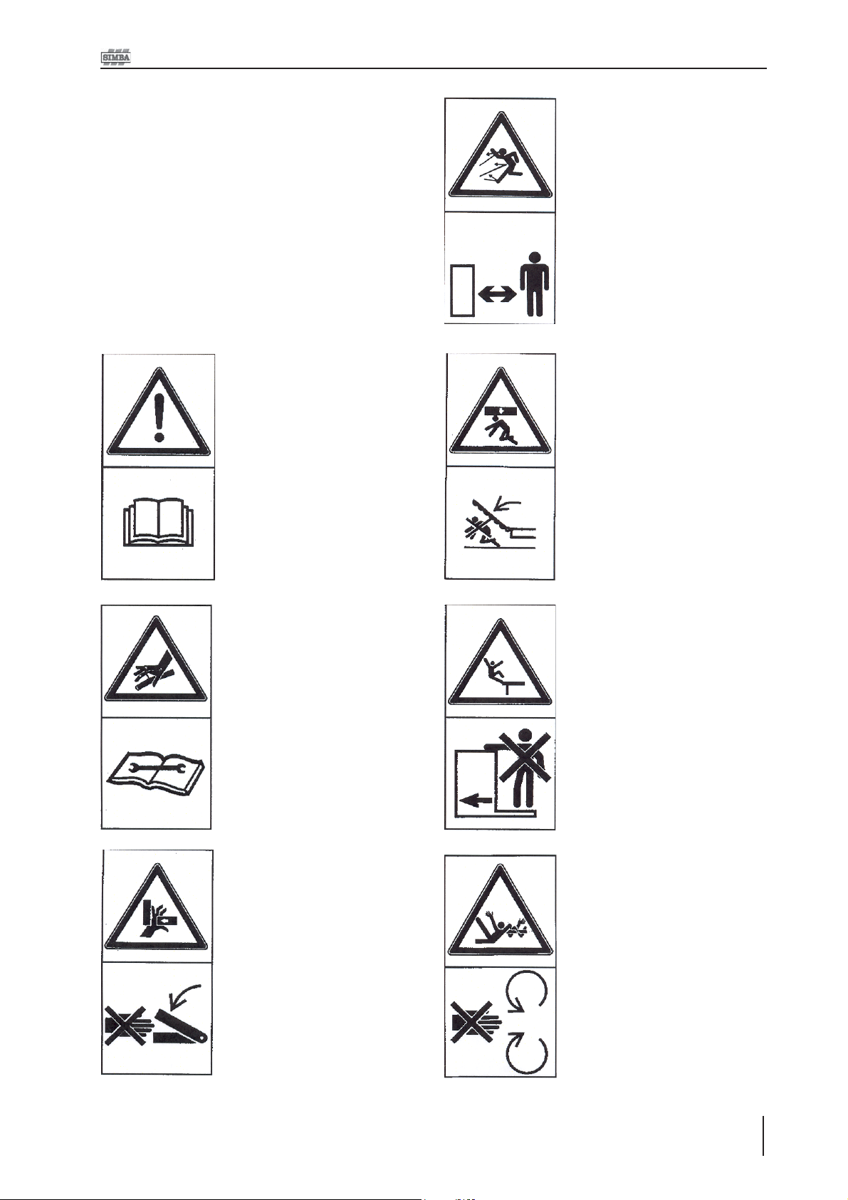
1.1 Safety Symbols
On the machine
Read and observe the Operating Instructions before
starting up the machine!
Parts may fly off during
operation. Keep a safe
distance away from the
machine!
Keep clear of the working
range of foldable machine
components!
Watch out for escaping
pressurised fluids! Follow
the instructions in the
Operating Instructions!
Never reach into areas
where there is a danger of
being crushed by moving
parts!
No passengers are allowed
on the machine!
Never reach into any
revolving parts!
Operating Instructions
9X-Press Trailing Kit
Page 10

1. Safety Data
Refer to Operating
Instructions before
attempting maintenance.
Operating Instructions:
The Operating Instructions distinguish
between three different types of warning and
safety instructions. The following graphic
symbols are used:
Important!
Risk of injury!
Risk of fatal and serious injuries!
It is important that all the safety instructions
contained in these Operating Instructions
and all the warning signs on the machine
are read carefully.
Ensure that the warning signs are legible.
Replace any signs that are missing or
damaged.
These instructions must be followed in order
to prevent accidents. Inform other users of
the warnings and safety instructions.
Do not carry out any operations which may
affect safe use of the machine.
X-Press Trailing Kit
10
Operating Instructions
Page 11

1. Safety Data
1.2 Use for the Intended
Purpose
The X-Press Trailing Kit is built using the
latest technology and in accordance with the
relevant recognised safety regulations.
However, risks of injury for the operator or third
parties and impairment of the machine or
other tangible assets can arise during use.
The machine is only to be operated when in
a technically perfect condition and for the
intended purpose, taking into consideration
safety and risks and following the Operating
Instructions. In particular, faults that can
impair safety are to be remedied
immediately.
Original parts and accessories from SIMBA
have been specially designed for this
machine. Spare parts and accessories not
supplied by us have not been tested or
authorised. Installation or use of non-original
SIMBA products may have a detrimental
effect on specific design features of the
machine and affect the safety of machine
operators and the machine itself. SIMBA will
accept no liability for damage resulting from
the use of non-original parts or accessories.
1.3 Operational Safety
The machine is to be put in operation only
after instruction has been provided by an
employee of the authorised dealer or an
employee of SIMBA. The “Machine
Registration” form is to be completed and
returned to SIMBA.
All protective and safety equipment, such
as removable protective equipment, must be
in place and functioning reliably before the
machine is put in use.
Check screws and bolts regularly for
tightness and retighten if necessary.
In the event of malfunctions, stop and
secure the machine immediately.
Ensure that any faults are remedied
immediately.
1.3.1 No Liability for
Consequential Damage
The X-Press Trailing Kit has been
manufactured by SIMBA with great care.
However, problems may still occur when it is
used for the intended purpose. These may
include:
The SIMBA X-Press Trailing Kit is designed
solely to enhance a cultivation implement.
Use for any other purpose, e.g., as a means
of transport, will be deemed to be improper
use. SIMBA will accept no liability for damage
resulting from improper use. The risk will be
borne solely by the operator.
• Worn wearing parts.
• Damage caused by external factors.
• Incorrect driving speeds.
• Incorrect setting of the unit (incorrect
attachment, non-adherence to the Setting
instructions).
Therefore, it is crucial to always
check your machine before and
during operation for correct
operation.
Compensation claims for damage which has
not occurred to the machine is excluded. This
includes any consequential damage resulting
from incorrect operation.
11X-Press Trailing Kit
Operating Instructions
Page 12

1. Safety Data
1.4 Road Traffic Safety
When driving on public roads, tracks and
areas, it is important to observe the relevant
road traffic laws as well as the specific
regulations relating to this machine.
Pay attention to the permitted axle
loads, tyre carrying capacity, and
total weight in order to maintain
adequate braking and steerability.
Passengers on the machine are
strictly forbidden!
Max. road transport speed 16mph
(25km/h).
1.5 Accident Prevention
1.5.3 During Operation
Ensure that the working range and the area
around the machine are clear (children!)
before operating the machine.
Always ensure adequate visibility!
Do not stand on the machine while it is in
operation!
Operators must have a suitable valid driving
licence in order to drive on public roads. In
the operating area, the operator is
responsible for third parties.
The person in charge must:
• provide the operator with a copy of the
Operating Instructions, and
In addition to the Operating Instructions, it is
important to observe the accident prevention
regulations specified by agricultural trade
associations.
1.5.1 Hitching-up the
machine
There is a risk of injury when hitching/
unhitching the machine. Observe the following:
• Secure the machine against rolling.
• Take special care when reversing the tractor!
• There is a risk of being crushed between
the machine and the tractor!
• Park the machine on firm, level ground.
1.5.2 Changing Equipment
• Secure the machine to prevent it from
accidentally rolling away!
• Use suitable supports to secure any raised
frame sections suspended above you!
• Caution! Risk of injury due to projecting parts!
• ensure that the operator has read and
understood the instructions.
• make sure that the operator is aware of the
specific regulations relating to the machine
when driving on public roads.
Never climb on to rotating parts such
as the roll unit. These parts may
rotate causing you to slip and suffer
serious injury!
X-Press Trailing Kit
12
Operating Instructions
Page 13

1. Safety Data
1.6 Servicing &
Maintenance
Ensure that regular checks and inspections
are always carried out within the periods
required by law or specified in these
Operating Instructions.
When carrying out service and maintenance
work always:
• switch off the tractor engine and remove
the ignition key.
• wait until all the machine parts have
stopped moving.
• depressurize the hydraulic system.
Prior to performing maintenance and
servicing work, ensure that the machine is
positioned on solid, level ground and is
secured to prevent it rolling away. Do not
use any parts to climb on to the machine
unless they are specifically designed for this
purpose.
1.7 Operating Areas
The operating areas include the drawbar,
hydraulic connections and depth adjustment
equipment as well as all operating points
requiring maintenance.
All operating areas will be specified and
described in detail in the following chapters
on servicing and maintenance.
Observe all safety regulations included in the
Section dealing with Safety, and in the subsequent sections.
1.8 Authorised Operators
Only those persons who have been
authorised and instructed by the operator may
operate the machine. The operator must be
at least 16 years of age.
1.9 Protective Equipment
For operation and maintenance, you require:
Before cleaning the machine with water,
steam jets (high-pressure cleaning
apparatus) or other cleaning agents, cover
all openings into which, for reasons of safety
or operation, no water, steam or cleaning
agents are to penetrate (bearings, for
instance).
Next, check all hydraulic lines for leaks, loose
connections, chafe marks and damage.
Remedy any deficiencies immediately!
Lubricate all the lubricating points to force
out any trapped water.
In the case of hydraulic cylinders that have
been cleaned using high pressure equipment
ensure that all hydraulic circuits are functional
and pressurised fully in both directions. This
provides the necessary coating of oil onto
cylinder rods after cleaning.
• Tight fitting clothing.
•Strong protective gloves (to provide
protection against sharp-edged machine
components).
• Protective goggles (to stop dirt getting into
your eyes).
When carrying out servicing and maintenance
work, retighten any loose screw connections.
13X-Press Trailing Kit
Operating Instructions
Page 14

2. Transportation / Installation
2. Transportation and
Installation
Transportation and initial installation of the
machine are described in this chapter.
2.1 Delivery
The Trailing Kit is normally delivered, fully
assembled on a machine. Some Trailing Kits
may be delivered as a package of parts
requiring assembly onto an X-Press.
• The machine can be lifted off with a crane
or other suitable lifting equipment.
• The machine should be hitched to a tractor
and driven off a low-loader.
2.2 Transportation
The X-Press can be transported on public
roads by hitching it up to a tractor or on a lowloader.
• It is important to observe the permitted
dimensions and weights when transporting the
machine.
2.3 Installation
When carrying out installation and
maintenance work there is a higher risk of
injury. It is important that you familiarise
yourself with the machine and read the
Operating Instructions beforehand.
Operator instruction and initial installation of
the machine are carried out by our service
technicians or authorised distributors.
The machine must not be used in any way
beforehand! The machine can only be
released for operation after instructions have
been provided by our service technicians or
authorised distributors.
• If any modules or parts have been removed
for transportation, these shall be mounted by
our service technicians/authorised dealers
before the instruction takes place.
• Check all important screw connections!
• Lubricate all nipples and joints!
• Check all hydraulic connections and lines
for damage.
• If the machine is transported on a trailer or a
low-loader, it must be secured using straps
or other devices.
• Before transporting the machine on public
roads, it must be adjusted to its transportation
position and the stipulations relating to road
transportation fulfilled.
• The maximum permissible speed is 25 km /h.
X-Press Trailing Kit
14
Operating Instructions
Page 15

2. Transportation / Installation
2.4 Hitching Up
2.4.1 Hitching up a Tractor
to an X-Press fitted with a
Trailing Kit / Preparing for
Transport
When hitching-up the machine,
ensure that no-one is between the
tractor and the machine.
When the X-Press is parked for
extended periods of time it should
ideally be left in the unfolded, i.e.
work position for stability, safety and
ease of access for maintenance.
However, parking the X-Press in the
folded position (ensuring that the
wing cylinder taps are closed) is
acceptable in the normal course of
operation.
Tractor Oil Flow Adjustment:
As a general rule the tractor oil flow
rate should be set in the lowest
setting before starting. This can then
be increased to allow the desired
rate of operation as applicable. This
will minimise excessive oil flow and
consequent power usage and heat
generation.
4. Raise the front of the machine and move
the parking stand to the work position.
5. If the machine is already folded it is now
ready for transport. If the machine is
unfolded please refer to 2.5.2.
Ensure that the wing taps are closed
before transporting the machine.
2.5 Folding and Unfolding
2.5.1 Unfolding into the Work
Position
1 Fully raise the machine on the transport
axle and the front linkage.
2 Open the taps on the wing cylinders.
3 Unfold the wings and continue to
pressure down to ensure they will hold
in work.
2.5.2 Folding into the
Transport Position
1 Fully raise the machine on the transport
axle and the front linkage.
1. Reverse the tractor up to the bar coupler
and engage the link arms.
2. Ensure the tractor hydraulics are
depressurised and in the locked or
closed (not float) setting.
3. Couple the hydraulic hoses to the tractor
ensuring that the two wing hoses
(yellow) are together and the lift cylinder
hoses (red) are together. (if the optional
front cylinder is fitted connect these
hoses also).
2 Fold the wings.
3 Shut the taps on the wing cylinders to
secure them for transport.
4 Clean any loose material off the
machine to avoid dropping onto the
carriageway.
5 The machine is now ready for road
transport.
Road transport speed should not
exceed 25kmh (16mph) .
15X-Press Trailing Kit
Operating Instructions
Page 16

2. Transportation / Installation
2.5 When driving on the
road
When driving on the road the machine must
be converted to the transportation position.
When driving on the road, raise the
machine completely to prevent the
working elements dragging on the
ground.
Ensure that the tractor rear lights
are visible from behind during
transport.
2.6 Parking the machine
In order to avoid damage as a result of
moisture, the machine should be parked, if
possible, indoors or under cover.
When manoeuvring the machine,
pay attention to your surroundings.
Ensure that nobody is in the
manoeuvring area (watch for
children!).
• Park the machine on level and solid ground.
• Raise the machine and lower the parking
stand.
• Lower the machine to the ground, ensuring
that it is stable.
• Disengage from the linkage and drive
forward slowly until the tractor is clear.
• Switch off the tractor.
• Disconnect hydraulic and electric lines from
the tractor.
X-Press Trailing Kit
16
Operating Instructions
Page 17

3. Adjustment/Operation
3.1 Description
5
4
3. Adjustment / Operation
6
7
3
2
Fig. 3.01: Simba 4m Mounted X-Press with Trailing Kit fitted
1. Bar Coupler
2. Drawbar
3. Front Lights
4. Transport Wheels
5. Rear Lights
6. Rear Lift Cylinder
7. Optional Front Lift Cylinder
The SIMBA X-Press Trailing Kit can be fitted
to 4m Folding Mounted X-Presses
manufactured from 2007 onwards. The kit
converts a 3 point linkage machine requiring
125-150hp into a semi mounted trailed unit
requiring 100-125hp.
1
The wheel units are used for road transport
and headland turns. The machine is lifted
clear of the ground using the rear hydraulic
cylinder.
17X-Press Trailing Kit
Operating Instructions
Page 18

3. Adjustment / Operation
3.2 Work Settings
The X-Press should be run with the chassis
level to slightly tail low. In practice it is possible
to use the X-Press on ground conditions that
are unsuitable to achieve the desired effect,
and it is usually possible to operate the DD
Light roll without regular blockage under such
unsuitable conditions, assuming that the roll
assemblies are tight, the scrapers correctly
adjusted and rings smooth. As such,
especially under wet conditions, it is advisable
to check on the cultivation effect of the XPress.
Optimum performance has been found to be
achieved when the DD Light roll rings have
worn away the painted finish leaving a smooth
shiny surface. When the DD Light rings are
new or rusty, soil may tend to pick up on the
surface and blockage may occur, this will
reduce when the rings are shiny again.
The X-Press should be lifted fully clear of the
ground onto the transport wheels for all
headland turns. Turning with the disc units or
roller on the ground could lead to damage of
these components.
The changes must be made with the finished
cultivation in mind. Increasing rear blade
angle could lead to blocking of the blades /
roller in some circumstances.
If the rear roller is not giving enough
consolidation the tractor linkage may be
raised slightly to transfer weight to the roller.
Alternatively, reducing forward speed will
allow the roller more time to consolidate the
ground.
If an optional front cylinder is fitted to the
machine this can be used to alter the front to
rear pitch of the machine.
3.3 Adjusting Depth
Working depth is controlled using the tractor
linkage and the roll linkage.
Roll depth is controlled using the depth stops
and pins on the roll linkage. Reversing the
depth stop through 180° and refitting gives a
finer depth adjustment.
In work machine will want to normally move to
the left due to the forces acting on the front
and rear gangs. This can be countered by
allowing the machine to be offset from the
tractor centre line by enabling the tractor
linkage to float sideways. This is done by
removing or loosening the linkage sway bars.
If the machine always moves to the left either:
a) reduce the front gang angle to reduce
the forces acting on the front blades
which will move the machine towards
the centre or
b) increase the angle on the rear blades
to increase the forces acting on them.
Fig. 3.02: X-Press with Trailing Kit in work position
When the depth has been altered, lower the
machine into work and check operation. If
the depth change has been significant then
other setting could be affected. This could
be chassis pitch (front to rear) and disc angle
for the given depth.
A small amount of cultivation, eg. a 20 metre
run, should be carried out before altering
these settings to check whether they are now
suitable for the cultivation effect required.
These settings should be addressed
immediately to prevent too much work being
carried out.
X-Press Trailing Kit
18
Operating Instructions
Page 19

3. Adjustment / Operation
3.4 Work Instructions
Driving speed
The X-Press can be driven at speeds of up
to 12 km/h.
This depends on the field conditions (type of
soil, surface trash, etc.).
Drive more slowly if the conditions are difficult
or a firmer finish is required.
Turning:
The X-Press should be lifted fully
clear of the ground onto the transport
wheels for all headland turns (using
the rear cylinder). Turning with the
disc units or roller on the ground
could lead to damage of these
components.
The transport wheels should be fully raised in
work.
3.5 Parking the
3.6 Checks
The working quality depends on the
adjustments and checks made prior to and
during work, as well as on regular servicing
and maintenance of the machine.
Before beginning work it is therefore
important to carry out any necessary servicing
and to lubricate the machine as required.
Checks prior to, and during
work:
• Is the machine correctly hitched up and the
coupling device locked?
• Have the hydraulic lines been connected
according to the colour coding?
• Is the machine in a level operating position
and the working depth set correctly?
Working Elements
• Are the discs and other cultivation tools in a
serviceable condition?
• Are the scrapers still operable, so that the
rolls do not jam?
machine
In order to avoid damage as a
result of moisture, the machine
should be parked, if possible, indoors or
under cover.
When manoeuvring the machine, pay attention
to your surroundings. Ensure that nobody is
in the manoeuvring area (watch for children!).
• Park the machine on level and solid ground.
• Raise the machine and lower the parking
stand.
• Lower the machine to the ground, ensuring
that it is stable.
• Disengage from the linkage and drive
forward slowly until the tractor is clear.
• Switch off the tractor.
• Disconnect hydraulic and electric lines from
Operating Instructions
19X-Press Trailing Kit
Page 20

4. Servicing and Maintenance
4. Servicing and
Maintenance
Follow the safety instructions for
servicing and maintenance.
These instructions refer only to the
Trailing Kit. For detailed
maintenance instructions for your
X-Press refer to the Operator‘s
Manual.
4.1 Servicing
Your machine has been designed and
constructed for maximum performance,
operational efficiency and operator
friendliness under a wide variety of operating
conditions.
Prior to delivery, your machine has
been checked at the factory and by
your authorised dealer to ensure that
you receive a machine in optimum
condition.
To ensure trouble-free operation, it is
important that servicing and maintenance
work is performed at the recommended
intervals.
4.2 Cleaning
In order to ensure that the machine is always
in operating condition and to achieve
optimum performance, perform the cleaning
and servicing work at regular intervals.
4.3 Operator Support
If you have a problem, please contact your
dealer. They will endeavour to solve any
problems which may occur and provide you
with support at all times.
In order to enable your dealer to deal with
problems as quickly as possible, it helps if
you can provide them with the following data.
Always state the:
• Customer Number
• Name and Address
• Machine Model
• Serial Number of Machine
• Date of Purchase and Operating Hours
• Type of Problem
4.4 Maintenance Intervals
Apart from daily maintenance, the
maintenance intervals are based on the
number of operating hours and time data.
Keep a record of your operating hours to
ensure that the specified maintenance
intervals are adhered to as closely as
possible.
Never use a machine that is due for
maintenance. Ensure that all deficiencies
found during regular checks are remedied
immediately.
Avoid sharp-edged and pointed
parts when working on the
machine.
X-Press Trailing Kit
20
Operating Instructions
Place the machine on suitable
supports when working
underneath! Do not work under a
machine which is not supported!
4.5 Wheel Hubs
Wheel hub maintenance and
servicing should be carried out by
an authorised Simba dealer.
Page 21

y
(
)
4. Servicing and Maintenance
4.6 Maintenance Overview
After first operation Instructions Interval Note
Check all screw, bolt and plug
connections
Lubricate machine See overview of lubricating points --- Page 21
During operation
Lubricate machine See overview of lubricating points --- Page 21
Hydraulic system and
components
Parking Stand Check condition and function daily --After season
Lubricate machine See overview of lubricating points --- Page 21
Bolts Grease any exposed threads --- --Entire machine Carry out cleaning and maintenance --- --After 4 years
Hydraulic pipes (if applicable) Replace MRL Anh I EN 1533
if applicable
Check they are firmly seated. Tighten
/ Secure if necessar
Check seals, signs of crushing/wear,
function and condition
--- ---
daily ---
4.7 Overview of Lubricating Points
X-Press Trailing Kit Lubrication Points Interval Diag. No.
Linkage Pivots 50 hours 4.01
Transport Axle Cylinder / Optional Front Cyl. 50 hours 4.02
Wheel Hubs
cap s hould be removed and hub pac ked w ith grease)
(Note: on hubs w ithout nipples fitted hub
È
È
Fig. 4.01: Bar Coupler Grease Points
Fig. 4.02: Lift Cylinder Grease Point
600 hours 4.03
È
Fig. 4.03: Wheel Hub Grease Points
È
21X-Press Trailing Kit
Operating Instructions
Page 22

4. Servicing and Maintenance
4.8 Lubricating the
Machine
Please read the section entitled "Using
Lubricants" carefully before lubricating the
machine.
The machine must be lubricated regularly in
order for it to remain serviceable. Regular
lubrication also contributes towards extending
the service life of your machine.
The recommended lubricating intervals are
specified in "Inspection" and "Maintenance
Intervals".
After it has been washed using a highpressure hose or steam cleaned, the machine
should always be lubricated using a grease
gun. Ensure that the universal joints and
splined shafts are lubricated regularly.
4.9 Handling of Lubricants
Please ensure that you read the following
instructions as well as the relevant
information. This also applies to any of your
employees who handle lubricants.
Hygiene
Lubricants do not present a health hazard
provided they are used for their specified
purpose.
Always exercise extreme care and observe
the recommended hygiene rules when
handling mineral oil products. Details of these
handling regulations can be found in
information provided by the health authorities.
Storage and Handling
• Always store lubricants where they cannot be
accessed by children.
• Never store lubricants in open or unlabelled
containers.
Fresh Oil
• Apart from taking the usual care and observing hygiene rules, there is no need to take
any special precautions when handling fresh
oil.
Waste Oil
• Waste oil can contain harmful contaminants
which may cause skin cancer, allergies and
other illnesses.
Attention!
Oil is a toxic substance. Should you swallow
any oil, do not try to vomit. Contact a doctor
immediately.
Protect your hands with barrier cream or wear
gloves to avoid contact with the skin. Wash
off any traces of oil thoroughly with soap and
hot water.
In the case of prolonged skin contact,
lubricants - especially low-viscosity oils - may
remove the natural layer of fat contained in
the skin, resulting in dryness and possible
irritation .
It is important to take extreme care when
handling waste oil as it may contain other
irritants.
Vapours given off by cleaning agents and oils
are also a potential health hazard.
You should therefore not carry any oily cloths
around. Change soiled work clothing as soon
as possible.
X-Press Trailing Kit
22
Operating Instructions
• Wash your skin thoroughly with soap and water.
• Use special cleaning agents to clean any
dirt off your hands.
• Never wash oil residue from your skin with
petrol, diesel fuel or paraffin.
• Avoid skin contact with any oily clothing.
• Do not keep any oily rags in your pockets.
• Wash soiled clothing before wearing it
again.
• Ensure that any oily footwear is disposed of in
the proper manner.
Page 23

4. Servicing and Maintenance
Measures in case of injury
through oil
Eyes:
Should any oil be splashed into your eyes,
rinse with water for 15 minutes. If the eye is
still irritated, contact a doctor immediately
If oil is swallowed
If oil is swallowed, it is important not to induce
vomiting. Contact a doctor immediately.
Skin irritation caused by oil
In case of prolonged skin contact, wash off
the oil with soap and water.
Oil Spills
Use either sand or a suitable granular
absorbent to soak up any spilt oil. Dispose of
the oil-contaminated absorbent in the proper
manner.
Oil Fires
Never use water to extinguish an oil fire. The
oil will float on the water causing the fire to
spread.
4.10 Lubricants &
Hydraulic Oil
Hydraulic System
The hydraulic fluid from the tractor is mixed
with the hydraulic fluid from the machine.
The supplied machine hydraulic system
contains Total AZOLLA ZS 32 oil.
Lubricants
Simba strongly recommend the use of
Lithium Complex EP2 Grease in the disc
hubs of your X-Press. This grease is a
Lithium Complex soap dispersed in a mineral oil and is interpreted by IARC as being
non-carcinogenic. Grease cartridges are
available from Simba (P12710). Using this
grease in combination with the labyrinth type
seal it is permissible to lengthen the greasing interval on the disc hubs to 200 hours.
If using a standard agricultural grease the
disc hubs should be lubricated every 50
hours.
Burning oil-lubricant must be extinguished
using a carbon dioxide powder or foam
extinguisher. Always wear respiratory
equipment when dealing with fires of this type.
Waste Oil Disposal
Oil-contaminated waste and used oil must be
disposed of in accordance with current
legislation.
Waste oil must be collected and disposed of
in accordance with local regulations. Never
pour used oil into unsealed sewage systems
or drains or onto the ground.
Advantages of Lithium Complex EP2
Grease
Excellent mechanical stability.
Excellent load carrying properties.
Wide temperature range.
Excellent oxidation stability.
Excellent water resistance.
Compatability with other greases.
All other lubricating points on the machine can
be lubricated with multigrade lubricating
grease as specified in DIN 51825 KP/2K -
40.
Operating Instructions
23X-Press Trailing Kit
Page 24

5. Parts & Assembly
X-Press Trailing Kit
24
Operating Instructions
Page 25

5. Parts & Assembly
Table of contents
Trailing Kit Complete Assembly .............. 26
Drawbar Assembly ................................. 28
Lift Axle Assembly .................................. 30
Unbraked Axle Assembly ........................ 32
Rear Hydraulic Assembly ....................... 34
Optional Front Hydraulic Assembly ......... 36
Light Kit ................................................. 38
Light Kit (for Pre-2008 machines) ........... 40
TurboJet Mounting Kit............................. 42
Spreader Bar Assembly ......................... 44
5. Parts & Assembly
Operating Instructions
25X-Press Trailing Kit
Page 26

5. Parts & Assembly
A
AS3605
ARH
14/12/2007
XPTK
TRAILING KIT XPTK - XPRESS 4.0m FW
X-Press Trailing Kit
26
Operating Instructions
Page 27

5. Parts & Assembly
AS3605
TRAILING KIT XPTK
XPRESS 4.0m FW
ITEM PART NO DESCRIPTION QTY COMMENTS
AS2684 SPREADER RAIL MOUNTING 1
1
AS3402 LIFT AXLE ASSEMBLY - XPTK 1
2
AS3403 HYDRAULIC ASSEMBLY - LIFT XPT K 1
3
AS3405 LIGHT KIT PR E 2008 - XPT K 1
4
AS3406 LIGHT KIT FRONT - XPTK 1
5
AS3407 AXLE ASSEMBLY - NON BRAKED - XPTK 1
6
AS3606 DRAWBAR ASSEMBLY - XPTK 1
7
AS3614 HYDRAULIC ASSEMBLY - LIFT XPT K 1
8
AS3624 TURBOJET 6 MOUNTING KIT 1
9
P13013 MANUAL CASE Ø100 1
10
P16867 MANUAL - XPTK 2009 1
11
12
13
14
15
16
17
18
19
20
21
22
23
24
25
26
27
28
29
30
31
32
33
34
35
36
37
38
39
40
41
42
43
44
45
46
47
48
49
50
(OPTION )
Operating Instructions
27X-Press Trailing Kit
Page 28

5. Parts & Assembly
D
AS3606
ARH
03/12/2008
X-Press Trailing Kit
28
Operating Instructions
DRAWBAR ASSEMBLY - XPTK
Page 29

5. Parts & Assembly
AS3606
DR AW BAR ASSEMBLY
XPT K
ITEM PART NO DESCRIPTION QTY COMMENTS
P00071 NIPPLE - GREASE 2
1
P00205 QUICK RELEASE MALE - ½" BSP 2
2
P01102 BOLT M16x70 GR. 8.8 4
3
P02008 NUT LOCK M16 'TYPE T ' 6
4
P02263 DOWTY SEAL ½" BSP 2
5
P02483 LYNCH PIN CAT 1 2
6
P02600 WASHER FLAT M10 8
7
P02602 WASHER FLAT M16 12
8
P02608 WASHER FLAT M30 1
9
P02649 BOLT M16x90 GR. 8.8 2
10
P03686 ADAPTOR MALE - MALE ½"-3/8" BSP 2
11
P04127 BUSH SPRUNG - Ø40xØ32x25 3
12
P04423 LYNCH PIN CAT 3 2
13
P04753 BOLT M8x60 GR. 8.8 4
14
P05401 WASHER SPRING M6 2
15
P05534 NUT LOCK M10 6
16
P06641 ADAPT OR MALE - MALE 3/8"-3/8" BSP 2
17
P09092 HOSE STOWAGE PLATE 1
18
P09142 CLAMP PLATE ¼" 4
19
P10231 CLAMP STAUFF 3/8" 2 HOSE 8
20
P10293 BOLT M6x20 GR. 8.8 2
21
P10636 BUSH SPRUNG - Ø40xØ31x20 2
22
P11077 B OLT M 10x50 GR.8.8 2
23
P11642 DECAL - AT T ENT ION 1
24
P11644 DECAL - DO NOT RIDE 1
25
P11645 DECAL - HAND TRAP 1
26
P11695 DECAL - GREASE 50 HOURS 2
27
P11697 DECAL - ANTI TAMPER 1
28
P12559 DECAL - UNBRAKED 1
29
P12690 BOLT M10x30 GR. 8.8 2
30
P13387 DECAL - SIMBA 85x150 2
31
P13843 DECAL - X-PRESS 62x580 2
32
P14025 PIN Ø30x129 1
33
P14520 BOLT M10x70 GR8.8 2
34
P14754 BALL CAT 3 LOW ER Ø37 2
35
P14781 BUSH SPRUNG - Ø44xØ36x30 4
36
P14842-1 HA 3/8"X2500 F-F 2
37
P16246 LINKAGE ADAPTOR - XPT K 1
38
P16250 SPACER Ø60x38x10 2
39
P16283 PIN Ø16x83 1
40
P16284 HOSE PLATE 1
41
P16296 LOOM 4.3M - 12N M-F 1
42
P16854 BRACE FIXED EXTENSION 1
43
P16855 DRAWBAR - XPTK 1
44
P16856 LINKAGE BAR - 984mm 1
45
P16857 PARKING STAND 1
46
P16858 DRAWBAR BRACE - UPPER 1
47
P16864 PIN Ø36x225 1
48
P16865 PIN Ø36x230 1
49
P16925 BUSH - Ø39.75mm 2
50
Operating Instructions
29X-Press Trailing Kit
Page 30

5. Parts & Assembly
D
AS3402
ARH
10/01/2008
X-Press Trailing Kit
30
Operating Instructions
LIFT AXLE ASSEMBLY - XPTK
Page 31

5. Parts & Assembly
AS3402
LIFT AXLE AS SEMBLY
XPT K
ITEM PART NO DESCRIPTION QTY COMMENTS
1
2
3
4
5
6
7
8
9
10
11
12
13
14
15
16
17
18
19
20
21
22
23
24
25
26
27
28
29
30
31
32
33
34
35
36
37
38
39
40
41
42
43
44
45
46
47
48
49
50
P00789 BOLT M24x180 GR. 8.8 5
P01102 BOLT M16x70 GR. 8.8 4
P01901 BOLT M16x80 GR. 8.8 8
P02008 NU T LOCK M16 'TYPE T ' 12
P02010 NU T LOCK M24 6
P02483 LYNCH PIN CAT 1 4
P02602 WASHER FLAT M16 24
P02604 WASHER FLAT M24 Ø50 12
P02608 WASHER FLAT M30 4
P03118 BOLT M24x300 GR. 8.8 1
P04127 BUSH SPRUNG - Ø40xØ32x25 2
P04753 BOLT M8x60 GR. 8.8 1
P08802 SHIM KIT 7 PIECE 1
P09142 CLAMP PLATE ¼" 3
P10096 BOLT M8x35 GR. 8.8 2
P10231 CLAMP ST AUFF 3/8" 2 HOSE 4
P10636 BUSH SPRUNG - Ø40xØ31x20 8
P11644 DECAL - DO NOT RIDE 1
P11695 DECAL - GREASE 50 HOURS 1
P13387 DECAL - SIMBA 85x150 1
P13843 DECAL - X-PRESS 62x580 1
P14024 BACK PLAT E 2
P14025 PIN Ø30x129 1
P14072 PIN Ø30x93 3
P16243 CYLINDER - Ø100x130 - 50 1
P16252 AXLE BRACE - XPTK 1
P16253 LIFT AXLE - XPT K 1
P16254 AXLE MOU NT ING 1
P16542 RETAINING CLAMP 1
P16930 CLAMP PLATE M24x2H 2
Operating Instructions
31X-Press Trailing Kit
Page 32

5. Parts & Assembly
A
AS3407
ARH
10/01/2008
X-Press Trailing Kit
32
Operating Instructions
AXLE ASSEMBLY - NON BRAKED - XPTK
Page 33

5. Parts & Assembly
AS3407
AXLE - NON BR AKED
XPT K
ITEM PART NO DESCRIPTION QTY COMMENTS
1
2
3
4
5
6
7
8
9
10
11
12
13
14
15
16
17
18
19
20
21
22
23
24
25
26
27
28
29
30
31
32
33
34
35
36
37
38
39
40
41
42
43
44
45
46
47
48
49
50
P04128 WHEEL ASSY 400/60x15.5 6 STUD 2
P04412 RIM 400/60 - 6 STUD 1
P04413 TYRE 400/60-15.5 14PLY 1
P14182 BOT T OM AXLE C/W 6 ST UD HUB 1
Operating Instructions
33X-Press Trailing Kit
Page 34

5. Parts & Assembly
AAS3403
ARH
10/01/2008
V2
C2
C1
V1
HYDRAULIC ASSEMBLY - LIFT XPTK
X-Press Trailing Kit
34
Operating Instructions
Page 35

5. Parts & Assembly
AS3403
HYDRAULIC ASSEMBLY
LIFT XP T K
ITEM PART NO DESCRIPTION QTY COMMENTS
1
2
3
4
5
6
7
8
9
10
11
12
13
14
15
16
17
18
19
20
21
22
23
24
25
26
27
28
29
30
31
32
33
34
35
36
37
38
39
40
41
42
43
44
45
46
47
48
49
50
P00205 QUICK RELEASE MALE - ½" BSP 2
P02263 DOWTY SEAL ½" BSP 2
P03686 ADAPTOR MALE - MALE ½"-3/8" BSP 2
P03687 DOW T Y SEAL 3/8" BSP 7
P09314 MALE - MALE AD APT OR 3/8" BSP 4
P10227 ADAPTOR MALE-FEM 3/8" BSP 1
P11604 BANJO BOLT 3/8" 1
P11605 BANJO BLOCK 3/8" 1
P13690 XPTK HA 3/8"x350 1
P16243 CYLINDER - Ø100x130 - 50 1
P16285 CHECK VALVE FPD-3/8-35L 1
P16302 HA 3/8"X5000 F-F90 2
Operating Instructions
35X-Press Trailing Kit
Page 36

5. Parts & Assembly
B
AS3614
KSL
10/01/2008
X-Press Trailing Kit
36
Operating Instructions
HYDRAULIC ASSEMBLY - LIFT XPTK
Page 37

5. Parts & Assembly
AS3614
HYDRAULIC ASSEMBLY
LIFT XPTK (OPTIONAL FRONT CYLINDER)
ITEM PART NO DESCRIPTION QTY COMMENTS
1
2
3
4
5
6
7
8
9
10
11
12
13
14
15
16
17
18
19
20
21
22
23
24
25
26
27
28
29
30
31
32
33
34
35
36
37
38
39
40
41
42
43
44
45
46
47
48
49
50
P00205 QUICK RELEASE MALE - ½" BSP 2
P02263 DOWTY SEAL ½" BSP 2
P03686 ADAPTOR MALE - MALE ½"-3/8" BSP 2
P03687 DOW T Y SEAL 3/8" BSP 7
P04753 BOLT M8x60 GR. 8.8 1
P08802 SHIM KIT 7 PIECE 1
P09142 CLAMP PLATE ¼" 1
P09314 MALE - MALE AD APT OR 3/8" BSP 4
P09539 CAP FOR MALE - RED 2
P10227 ADAPTOR MALE-FEM 3/8" BSP 1
P10231 CLAMP ST AUFF 3/8" 2 HOSE 2
P11604 BANJO BOLT 3/8" 1
P11605 BANJO BLOCK 3/8" 1
P13690 XPTK HA 3/8"x350 1
P16243 CYLINDER - Ø100x130 - 50 1
P16284 HOSE PLATE 1
P16285 CHECK VALVE FPD-3/8-35L 1
P16871 HA - 1/2"x3000 F/F 90 SW 1
P16873 HA - 1/2"x3000 F/F 90 SW 1
Operating Instructions
37X-Press Trailing Kit
Page 38

5. Parts & Assembly
1009
BAS3406
(2700)
1009
658
ARH
10/01/2008
XPTK
X-Press Trailing Kit
38
Operating Instructions
LIGHT KIT FRONT - XPTK
Page 39

5. Parts & Assembly
AS3406
ITEM PART NO DESCRIPTION QTY COMMENTS
1
2
3
4
5
6
7
8
9
10
11
12
13
14
15
16
17
18
19
20
21
22
23
24
25
26
27
28
29
30
31
32
33
34
35
36
37
38
39
40
41
42
43
44
45
46
47
48
49
50
P00002 BOLT U M12 GR 8.8 70x54 2
P02007 NU T LOCK M12 4
P02601 WASHER FLAT M12 4
P04754 NU T LOCK M8 8
P05535 WASHER FLAT M8 16
P07543 PLASTIC END CAP 40x40 2
P09597 BOLT M8x25 GR. 8.8 8
P14973 LIGHT BEAM 1
P15560 LIGHT BOAR D FR H 1
P15561 LIGHT BOAR D FLH 1
LIGHT KIT FRONT - XPTK
Operating Instructions
39X-Press Trailing Kit
Page 40

5. Parts & Assembly
A
AS3405
ARH
10/01/2008
XPTK
LIGHT KIT PRE 2008 - XPTK
X-Press Trailing Kit
40
Operating Instructions
Page 41

5. Parts & Assembly
AS3405
LIGHT KIT PR E 2008
XPT K
ITEM PART NO DESCRIPTION QTY COMMENTS
1
2
3
4
5
6
7
8
9
10
11
12
13
14
15
16
17
18
19
20
21
22
23
24
25
26
27
28
29
30
31
32
33
34
35
36
37
38
39
40
41
42
43
44
45
46
47
48
49
50
P14973 LIGHT BEAM 1
P02601 WASHER FLAT M12 4
P02007 NU T LOCK M12 4
P00002 BOLT U M12 GR 8.8 70x54 2
P15562 LIGHT BOAR D RRH 1
P15563 LIGHT BOAR D RLH 1
P07543 PLASTIC END CAP 40x40 2
P09597 BOLT M8x25 GR. 8.8 8
P04754 NU T LOCK M8 8
P05535 WASHER FLAT M8 16
P15887 BASE LOOM - X-PRESS 4m FW 1
Operating Instructions
41X-Press Trailing Kit
Page 42

5. Parts & Assembly
AAS3624
PJG
11/02/2008
XP-4m FW TRAILED
PLATE Z
OF DRAWBAR AS SHOWN
MOUNT RADAR TO UNDERSIDE
ON LIFT AXLE.
MOUNT P16359 TO PLATE Z
TURBOJET 6 MOUNTING KIT
X-Press Trailing Kit
42
Operating Instructions
Page 43

5. Parts & Assembly
AS3624
TURBOJET 6
MOUNTING KIT
ITEM PART NO DESCRIPTION QTY COMMENTS
1
2
3
4
5
6
7
8
9
10
11
12
13
14
15
16
17
18
19
20
21
22
23
24
25
26
27
28
29
30
31
32
33
34
35
36
37
38
39
40
41
42
43
44
45
46
47
48
49
50
AS3576 TURBOJET 6 - GENERAL ASSEMBLY 1
P00003 BOLT M12x40 GR. 8.8 8
P01901 BOLT M16x80 GR. 8.8 4
P02007 NU T LOCK M12 12
P02008 NU T LOCK M16 'TYPE T ' 4
P02600 WASHER FLAT M10 6
P02601 WASHER FLAT M12 24
P02602 WASHER FLAT M16 8
P02789 BOLT M8x20 GR. 8.8 4
P03093 BOLT M12x75 GR. 8.8 4
P05534 NU T LOCK M10 3
P07522 ST EP 1000x300x45 1
P08817 WASHER SPRING M8 4
P11644 DECAL - DO NOT RIDE 1
P12690 BOLT M10x30 GR. 8.8 3
P15198 DECAL - SIMBA 65x114 4
P15589 RDS RADAR 1
P16359 TURBOJET MOUNT - XPTK 1
P16364 ST EP BRACKET 2
P16366 STEP BRACKET CLAMP 2
P16369 RADAR MOUNT 1
Operating Instructions
43X-Press Trailing Kit
Page 44

5. Parts & Assembly
50
304
304
A
304
304
304
304
304
B
AS2684
PJG
24/08/2006
DIMENSIONS FOR REFERENCE ONLY
FIT SPREADER PLATES BETWEEN
EVERY OTHER PAIR OF DD RINGS AS SHOWN
304
304
304
X-PRESS 4m F/W
304
304
50
X-Press Trailing Kit
44
Operating Instructions
SPREADER RAIL MOUNTING
Page 45

5. Parts & Assembly
AS2684
SPREADER BAR ASSEMBLY - X-PRESS
4.0m F/W
ITEM PART NO DESCRIPTION QTY COMMENTS
1
2
3
4
5
6
7
8
9
10
11
12
13
14
15
16
17
18
19
20
21
22
23
24
25
26
27
28
29
30
31
32
33
34
35
36
37
38
39
40
41
42
43
44
45
46
47
48
49
50
AS2520 DISTRIBUTOR HEAD ASSEMBLY 14
P02600 WASHER FLAT M10 24
P05534 NU T LOCK M10 12
P06403 BOLT M10x20 GR. 8.8 8
P10578 WASHER 3/8" SHAKEPROOF 4
P13961 BOLT U M10 GR 8.8 71x88 4
P14483 CHANN EL - 2m 2
P14520 BOLT M10x70 GR8.8 4
P14573 D/RAIL LOCK NUT 8
P15821 OSR RAIL PIVOT 4
P15893 OSR RAIL MOUNT 4
Operating Instructions
45X-Press Trailing Kit
Page 46

5. Parts & Assembly
X-Press Trailing Kit
46
Operating Instructions
 Loading...