

Page 1

From Serial No. 12682
P15061 30/1 1/06
Page 2

Solo
2
Operating Instructions
Page 3

Declaration of Conformity
DECLARATION OF CONFORMITY
Simba International Limited hereby declare that the Product described in this Operators Manual, and defined
by the Serial Number Plate attached to the Chassis of the Machine (a part copy of which is detailed overleaf
and must be completed indicating the relevant machine details), conforms with the following Directives and
Regulations, and has been certified accordingly .
EC Machinery Directive 89/392/EEC, as amended by 91/3688/EEC, 93/44/EEC, and
93/688/EEC.
In order to fulfill the requirements of health and safety described in the EC Directive, the following standards
and technical specifications have been taken into account:
EN 292 - 1
EN 292 - 2
THE MANUFACTURER
Simba International Limited
Woodbridge Road
SLEAFORD
NG34 7EW
Lincolnshire
NG34 7EW
England.
T elephone 01529 304654.
CERTIFIED ON BEHALF OF SIMBA INTERNA TIONAL LIMITED.
Rod Daffern
Chairman
Simba International Limited
Operating Instructions
3Solo
Page 4

Warranty
WARRANTY
TERMS AND CONDITIONS
In this warranty Simba International Ltd., is referred to as “the Compan y”.
1. Subject to the provisions of this warranty the Com pany w arrants each new m achine sold by
it to be sold free from any defect in material or workmanship for a period of 12 months from
date of installation with the end-user.
Some specific items have additional warranty over and above the standard 12 months.
Details of these can be obtained upon request directly from the distributor or Simba
International Ltd.
2. If the machine or part thereof supplied by the Company is not in accordance with the
warranty given in clause 1 the Com pany will at its option:
(a) make good the machine or part thereof at the Com pany’s expense, or
(b) make an allowance to the purchaser against the purchase price of the machine or
part thereof, or
(c) accept the return of the machine and at the buyers option either:
I) repay or allow the buyer the invoice price of the machine or part thereof, or
II) replace the machine or part thereof as is reasonably practical.
3. This warranty shall not oblige the Com pan y to make any paym ent in respect of loss of profit
or other consequential loss or contingent liability of the Purchaser alleged to arise from any
defect in the machine or impose any liability on the Company other than that contained in
clause 2.
4. Any claim under this warranty must be notified to the Company in writing specifying the
matters complained of within 14 days from the date of repair.
5. Any claim under this warranty mus t be made by the o riginal purchaser of the machine and
is not assignable to any third party.
6. If the purchaser hires out the machine to any third party the warranty shall apply only to
matters notified to the Company in writing within 90 days of the date of delivery and clause
1 shall be read as if the period of 90 days were substituted for the period of 12 months.
7. The warranty will cease to apply if:
(a) any parts not made, supplied or approved in writing by the Company are fitted to the
machine or
(b) any repair is carried out to the machine other than by or with the express written approval
of the Company or
(c) any alterations not expressly authorized by the Company in writing are made to the
machine or
(d) the m achine is damaged b y accident or
(e) the machine is abused or overloaded or used for a purpose or load beyond its design
capabilities, or used in conjunction with a tractor whose power output capability exceeds
the stated implement power requirement by more than 40%. For the purpose of these
terms and conditions, “stated implement power requirement” refers to wheeled tractors
unless specifically stated. These power requirements should be reduced by 20% when
used in conjunction with tracked tractors.
(f) the machine is operated as part of a ‘cultivation train’ where m ore than one implement is
being towed, without the express written approval of Simba International Ltd.
(g) any maintenance is not carried out in accordance with the service schedules in the
operator’s manual.
(h) the Installation and W arranty Registration Certificate is not received by Simba International
Ltd., Service Dept., Woodbridge Road, Sleaford, Lincolnshire, England, NG34 7EW , within
7 days of in s t alling a n ew mach in e.
Solo
4
Operating Instructions
Page 5

Machine Identification
Enter the relevant data in the following list upon
acceptance of the machine:
Ser ia l N umber
Type of M achine
Mach ine Width
Year of Construction
Delive r y Date
First O per at ion
Accessories
Operating Instructions/Sp are Parts List: November 2006
Machine Identification
Dealer Address: Name: ......................................................................
Street: ......................................................................
Place: ......................................................................
Tel.: ................................................................. ....
Dealer's Customer No.: ............................................................
SIMBA Address: SIMBA
Woodbridge Road Ind. Est.
Sleaford
Lincolnshire
NG34 7EW
Tel.: 01529 304654
Fax: 01529 413468
E-Mail: simba.international@simba.co.uk
SIMBA Customer No.: .................................................................
Operating Instructions
5Solo
Page 6

T able of Contents
Contents
Machine Identification.......................................................................................................5
Contents ..........................................................................................................................6
Introduction ............................................................................................. 8
Foreword .........................................................................................................................8
Warranty Guidelines .........................................................................................................8
1. Safety Data ..................................................................................... 9
1.1 Safety Symbols ..................................................................................................... 9
1.2 Use for the Intended Purpose .............................................................................. 11
1.3 Operational Safety .............................................................................................. 11
1.3.1 No Liability for Consequential Damage ............................................................... 11
1.4 Road Traf fic Safety..............................................................................................12
1.5 Accident Prevention ............................................................................................ 12
1.5.1 Hitching-up the machine ......................................................................................12
1.5.2 On the Hydraulic System .....................................................................................12
1.5.3 Changing Equipment........................................................................................... 13
1.5.4 During Operation................................................................................................. 13
1.6 Servicing & Maintenance ....................................................................................13
1.7 Operating Areas..................................................................................................14
1.8 Authorised Operators..........................................................................................14
1.9 Protective Equipment..........................................................................................14
2. Transportation and Installation .................................................. 15
2.1 Delivery...............................................................................................................15
2.2 Transportation .....................................................................................................15
2.3 Installation ...........................................................................................................15
2.4 Hitching Up .........................................................................................................16
2.4.1 Hitching up a Tractor to the Solo / Prep aring for Transport ...................................16
2.5 Folding and Unfolding .........................................................................................17
2.5.1 Unfolding into the Work Position..........................................................................17
2.5.2 Folding into the Transport Position ......................................................................17
2.6 Trailing Implements .............................................................................................18
2.6.1 Hitching a Press Roll to the Solo .........................................................................18
2.7 When driving on the road.....................................................................................18
2.8 Parking the machine ...........................................................................................18
3. Technical Data Solo ..................................................................... 19
4. Adjustment/Operation .................................................................. 20
4.1 Description .........................................................................................................20
4.2 Solo Designations...............................................................................................21
4.3 Disc Gangs.........................................................................................................22
4.4 Coulter Coverer...................................................................................................23
4.5 Double Disc Roller ..............................................................................................23
4.6 T erra-Grip T ines ..................................................................................................24
4.7 Pro-Lift T ines.......................................................................................................25
4.8 Pro-Lift Wings.....................................................................................................25
4.9 Work Settings .....................................................................................................26
Solo
6
Operating Instructions
Page 7

T able of Contents
4.10 St arting Settings..................................................................................................27
4.11 Depth Control...................................................................................................... 28
4.12 Work Instructions.................................................................................................28
4.13 Parking the machine ...........................................................................................28
4.14 Checks ............................................................................................................... 29
5. Ser vicing and Maintenance ......................................................... 30
5.1 Servicing.............................................................................................................30
5.2 Cleaning .............................................................................................................30
5.3 Tightening Disc Axles .......................................................................................... 30
5.4 T erra-Grip T ine Beams ........................................................................................30
5.5 T erra-Grip T ine Points .........................................................................................31
5.6 Pro-Lift T ines.......................................................................................................31
5.7 Double Disc Axles...............................................................................................31
5.8 Roll Wing Shims..................................................................................................31
5.9 Hydraulics ...........................................................................................................32
5.9.1 Drawbar & Axle Phasing .....................................................................................32
5.9.2 Pro-Lift Trip-Reset T ine Hydraulics ...................................................................... 33
5.9.3 2 Litre Accumulators............................................................................................34
5.9.4 Roll Hydraulics ....................................................................................................35
5.10 Changing Roll Configuration................................................................................36
5.1 1 Preparation for Storage.......................................................................................38
5.12 Operator Support ................................................................................................38
5.13 Maintenance Intervals..........................................................................................38
5.14 Maintenance Overview ........................................................................................39
5.15 Overview of Lubricating Points ............................................................................40
5.16 Lubricating the Machine ......................................................................................42
5.17 Handling of Lubricants.........................................................................................42
5.18 Lubricants & Hydraulic Oil ...................................................................................43
6. Faults and Remedies ......................................................................... 44
7. Parts & Assembly ............................................................................... 45
7.1 Parts & Assembly Contents................................................................................... 45
Operating Instructions
7Solo
Page 8

Introduction
Introduction
Foreword
Make sure you have read and follow the
Operating Instructions carefully before using
the machine. By doing so, you will avoid
accidents, reduce repair costs and downtime
and increase the reliability and service life
of your machine. Pay attention to the safety
instructions!
SIMBA will not accept any responsibility for
any damage or malfunctions resulting from
failure to comply with the Operating
Instructions.
These Operating Instructions will assist you
in getting to know your machine and in using
it correctly for its intended purposes. First,
you are given general instructions in
handling the machine. This is followed by
sections on servicing, maintenance and the
action to be taken should a malfunction
occur.
We reserve the right to alter
illustrations as well as technical data
and weights contained in these
Operating Instructions for the purpose
of improving the Solo.
Warranty Guidelines
1. The period of liability for material defects
(warranty) relating to our products is 12
months. In the case of written deviations
from the statutory provisions, these
agreements shall apply.
They shall become effective upon installation
of the machine with the end customer. All wear
parts are excluded from the warranty .
2. Warranty claims must be submitted to the
SIMBA Customer Service Department in
Sleaford via your dealer. It is only possible
to process claims which have been correctly
completed and submitted no later than 14
days after the date of repair .
These operating instructions are to be read
and followed by all persons working on or
with the machine, e.g.:
• Operation (including preparation, remedying
of faults in the operating sequence and
servicing).
• Maintenance (maintenance and inspection)
• Transportation.
T ogether with the Operating Instructions, you
receive a Spare Parts List and a Machine
Registration form. Field service technicians
will instruct you in the operation and
servicing of your machine. Following this,
the Machine Registration form is to be
returned to SIMBA. This confirms your
formal acceptance of the machine. The
warranty period begins on the date of delivery .
3. In the case of deliveries made under the
warranty which are subject to the return of
the old parts, the old parts must be returned
to SIMBA within 28 days after the damage
occurred.
4. In the case of deliveries made under the
warranty which are not subject to the return
of the old parts, these parts must be kept for
the purpose of further decisions for a period
of 3 months after receipt of the warranty claim.
5. Warranty repairs to be carried out by
outside companies, or repairs which are
expected to take more than 10 working
hours, must be agreed upon in advance with
the Customer Service Department.
Solo
8
Operating Instructions
Page 9
1. Safety Data
1. Safety Data
The following warnings and safety
instructions apply to all sections of these
Operating Instructions.
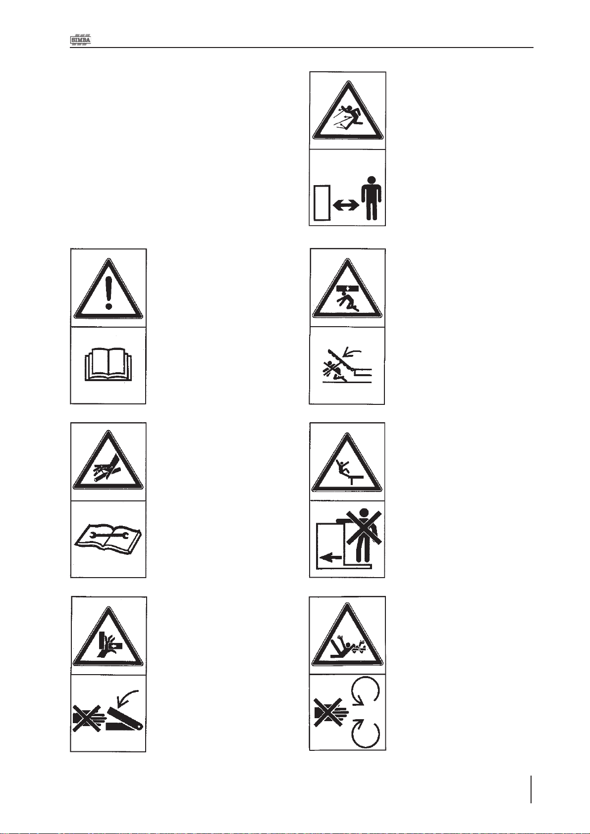
1.1 Safety Symbols
On the machine
Read and observe the Operating Instructions before
starting up the machine!
Parts may fly off during
operation. Keep a safe
distance away from the
machine!
Keep clear of the working
range of foldable machine
components!
Watch out for escaping
pressurised fluids! Follow
the instructions in the
Operating Instructions!
Never reach into areas
where there is a danger of
being crushed by moving
parts!
No passengers are allowed
on the machine!
Never reach into any
revolving parts!
Operating Instructions
9Solo
Page 10
1. Safety Data
Refer to Operating
Instructions before
attempting maintenance.
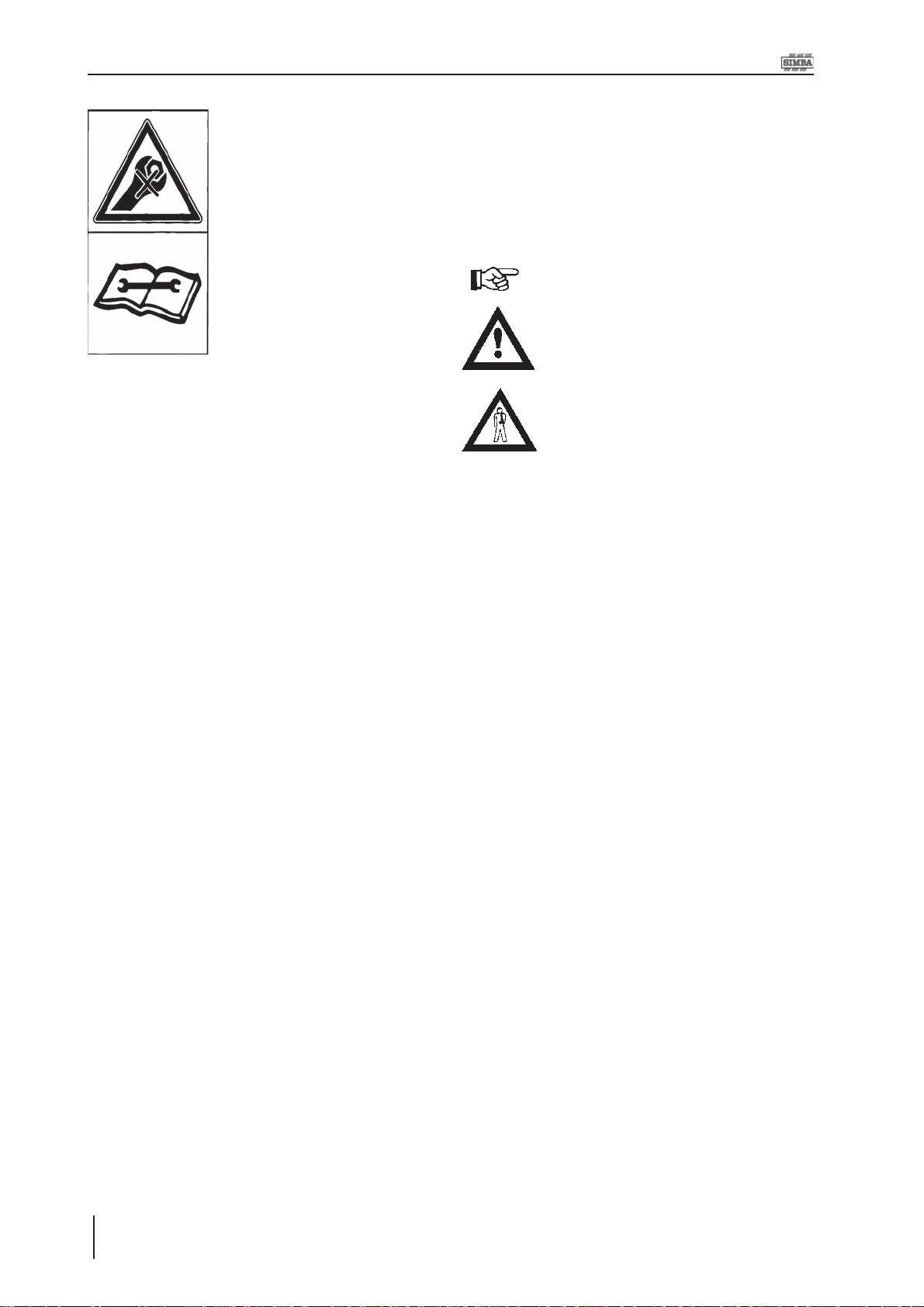
Operating Instructions:
The Operating Instructions distinguish
between three different types of warning and
safety instructions. The following graphic
symbols are used:
Important!
Risk of injury!
Risk of fatal and serious injuries!
It is important that all the safety instructions
contained in these Operating Instructions
and all the warning signs on the machine
are read carefully.
Ensure that the warning signs are legible.
Replace any signs that are missing or
damaged.
These instructions must be followed in order
to prevent accidents. Inform other users of
the warnings and safety instructions.
Do not carry out any operations which may
affect safe use of the machine.
Solo
10
Operating Instructions
Page 11

1. Safety Data
1.2 Use for the Intended
Purpose
The SIMBA Solo is built using the latest
technology and in accordance with the relevant recognised safety regulations. However,
risks of injury for the operator or third parties
and impairment of the machine or other
tangible assets can arise during use.
The machine is only to be operated when in
a technically perfect condition and for the
intended purpose, taking into consideration
safety and risks and following the Operating
Instructions. In particular, faults that can
impair safety are to be remedied
immediately.
Original parts and accessories from SIMBA
have been specially designed for this
machine. Spare parts and accessories not
supplied by us have not been tested or
authorised. Installation or use of non-original
SIMBA products may have a detrimental
effect on specific design features of the
machine and affect the safety of machine
operators and the machine itself. SIMBA will
accept no liability for damage resulting from
the use of non-original parts or accessories.
1.3 Operational Safety
The machine is to be put in operation only
after instruction has been provided by an
employee of the authorised dealer or an
employee of SIMBA. The “Machine
Registration” form is to be completed and
returned to SIMBA.
All protective and safety equipment, such
as removable protective equipment, must be
in place and functioning reliably before the
machine is put in use.
Check screws and bolts regularly for
tightness and retighten if necessary .
In the event of malfunctions, stop and
secure the machine immediately .
Ensure that any faults are remedied
immediately.
1.3.1 No Liability for
Consequential Damage
The Solo has been manufactured by SIMBA
with great care. However, problems may still
occur when it is used for the intended purpose.
These may include:
The SIMBA Solo is designed solely as a
cultivation implement. Use for any other
purpose, e.g., as a means of transport, will
be deemed to be improper use. SIMBA will
accept no liability for damage resulting from
improper use. The risk will be borne solely by
the operator.
• Worn wearing parts.
• Damage caused by external factors.
• Incorrect driving speeds.
• Incorrect setting of the unit (incorrect
attachment, non-adherence to the Setting
instructions).
Therefore, it is crucial to always
check your machine before and
during operation for correct
operation and adequate application
accuracy .
Compensation claims for damage which has
not occurred to the machine is excluded. This
includes any consequential damage resulting
from incorrect operation.
Operating Instructions
11Solo
Page 12

1. Safety Data
1.4 Road Traffic Safety
When driving on public roads, tracks and
areas, it is important to observe the relevant
road traffic laws as well as the specific
regulations relating to this machine.
Pay attention to the permitted axle
loads, tyre carrying capacity, and
total weight in order to maintain
adequate braking and steerability .
Passengers on the machine are
strictly forbidden!
Max. road transport speed 16mph
(25km/h).
1.5 Accident Prevention
In addition to the Operating Instructions, it is
important to observe the accident prevention
regulations specified by agricultural trade
associations.
1.5.1 Hitching-up the
machine
There is a risk of injury when hitching/
unhitching the machine. Observe the following:
• Secure the machine against rolling.
• T ake special care when reversing the tractor!
• There is a risk of being crushed between
the machine and the tractor!
• Park the machine on firm, level ground.
1.5.2 On the Hydraulic
System
Do not connect the hydraulic lines to the tractor
until both hydraulic systems (machine and
tractor) are depressurised.
Any hydraulic system containing an
accumulator can remain under
pressure permanently (even after
following manual depressurisation
procedures with a tractor /
implement combination). It is
therefore important to check all
lines, pipes, and screw
connections regularly for leaks and
any recognisable external
damage.
Only use appropriate aids when checking for
leaks. Repair any damage immediately.
Spurting oil can cause injuries and fires!
In case of injury , contact a doctor immediately .
Solo
12
Operating Instructions
The socket and plugs for the hydraulic
connections between the tractor and the
machine should be colour-coded in order to
avoid incorrect use.
Page 13

1. Safety Data
1.5.3 Changing Equipment
• Secure the machine to prevent it from
accidentally rolling away!
• Use suitable supports to secure any raised
frame sections suspended above you!
• Caution! Risk of injury due to projecting parts!
Never climb on to rotating parts such
as the roll unit. These parts may
rotate causing you to slip and suffer
serious injury!
1.5.4 During Operation
Ensure that the working range and the area
around the machine are clear (children!)
before operating the machine.
Always ensure adequate visibility!
Do not stand on the machine while it is in
operation!
Operators must have a valid driving licence
in order to drive on public roads. In the
operating area, the operator is responsible
for third parties.
The person in charge must:
• provide the operator with a copy of the
Operating Instructions, and
1.6 Servicing &
Maintenance
Ensure that regular checks and inspections
are always carried out within the periods
required by law or specified in these
Operating Instructions.
When carrying out service and maintenance
work always:
• switch off the tractor engine and remove
the ignition key.
• wait until all the machine parts have
stopped moving.
• depressurize the hydraulic system.
Prior to performing maintenance and
servicing work, ensure that the machine is
positioned on solid, level ground and is
secured to prevent it rolling away. Do not
use any parts to climb on to the machine
unless they are specifically designed for this
purpose.
Before cleaning the machine with water,
steam jets (high-pressure cleaning
apparatus) or other cleaning agents, cover
all openings into which, for reasons of safety
or operation, no water, steam or cleaning
agents are to penetrate (bearings, for
instance).
• ensure that the operator has read and
understood the instructions.
• make sure that the operator is aware of
the specific regulations relating to the
machine when driving on public roads.
Next, check all hydraulic lines for leaks, loose
connections, chafe marks and damage.
Remedy any deficiencies immediately!
Lubricate all the lubricating points to force
out any trapped water.
When carrying out servicing and maintenance
work, retighten any loose screw connections.
13Solo
Operating Instructions
Page 14

1. Safety Data
1.7 Operating Areas
The operating areas include the drawbar,
hydraulic connections and depth adjustment
equipment as well as all operating points
requiring maintenance.
All operating areas will be specified and
described in detail in the following chapters
on servicing and maintenance.
Observe all safety regulations included in the
Section dealing with Safety , and in the subsequent sections.
1.8 Authorised Operators
Only those persons who have been
authorised and instructed by the operator may
operate the machine. The operator must be
at least 16 years of age.
1.9 Protective Equipment
For operation and maintenance, you require:
• Tight fitting clothing.
•Strong protective gloves (to provide
protection against sharp-edged machine
components).
• Protective goggles (to stop dirt getting into
your eyes).
Solo
14
Operating Instructions
Page 15

2. Transportation / Inst allation
2. Transportation and
Installation
Transportation and initial installation of the
machine are described in this chapter.
2.1 Delivery
The machine is normally delivered, fully
assembled.
• The machine can be lifted off with a crane
or other suitable lifting equipment.
• The machine should be hitched to a tractor
and driven off a low-loader .
2.2 Transportation
The Solo can be transported on public roads
by hitching it up to a tractor or on a low-loader.
• It is important to observe the permitted
dimensions and weights when transporting the
machine.
• If the machine is transported on a trailer or a
low-loader, it must be secured using straps
or other devices.
2.3 Installation
When carrying out installation and
maintenance work there is a higher risk of
injury. It is important that you familiarise
yourself with the machine and read the
Operating Instructions beforehand.
Operator instruction and initial installation of
the machine are carried out by our service
technicians or authorised distributors.
The machine must not be used in any way
beforehand! The machine can only be
released for operation after instructions have
been provided by our service technicians or
authorised distributors.
• If any modules or parts have been removed
for transportation, these shall be mounted by
our service technicians/authorised dealers
before the instruction takes place.
• Check all important screw connections!
• Lubricate all nipples and joints!
• Check all hydraulic connections and lines
for damage.
• Before transporting the machine on public
roads, it must be adjusted to its transportation
position and the stipulations relating to road
transportation fulfilled.
• The maximum permissible speed is 25 km /h.
Operating Instructions
15Solo
Page 16

2. T ransportation / Installation
2.4 Hitching Up
2.4.1 Hitching up a Tractor
to the Solo / Preparing for
Transport
When hitching-up the machine,
ensure that no-one is between the
tractor and the machine.
When the Solo is parked for
extended periods of time it should
ideally be left in the unfolded, i.e.
work, position for stability , safety and
ease of access for maintenance.
However, parking the Solo in the
folded position (using the parking
pins provided) is acceptable in the
normal course of operation.
4. Carefully operate the hydraulics to lower
the drawbar and tilt the Solo onto the
road transport wheels. Fully extend the
drawbar cylinder and lift axle cylinder
and add in the requisite amount of shims
for road transport.
5. Ensure that the wing transport pins are
fitted.
6. If the machine is already folded it is now
ready for transport. If the machine is
unfolded then operate the fold circuit and
fit the wing transport pins. Refer to 2.5.2.
Tractor Oil Flow Adjustment:
As a general rule the tractor oil flow
rate should be set in the lowest
setting before starting. This can then
be increased to allow the desired
rate of operation as applicable. This
will minimise excessive oil flow and
consequent power usage and heat
generation.
1. Ensure the tractor hydraulics are
depressurised and in the locked or
closed (not float) setting.
2. Couple the hydraulic hoses to the tractor
ensuring that the two wing hoses
(yellow) are together , the two drawbar
cylinder hoses (red) are together and the
trip-reset tine hoses (green) - if
applicable - are together.
3. Connect the tractor to the drawbar using
the hydraulics to raise or lower the height
of the shackle.
Solo
16
Operating Instructions
Page 17

2. Transportation / Inst allation
2.5 Folding and Unfolding
2.5.1 Unfolding into the Work
Position
1. Raise the machine enough to facilitate
easy removal of shims from the lift axle
rams.
2. Remove the requisite amount of shims
from the lift axle rams - normally one
50mm silver shim will be left in place.
3. Lower the machine to a height where it
is comfortable to reach the disc gang
locking and adjustment handles.
Ensure gangs are clear of the ground.
4. Unlock the front and rear disc gangs,
rotate them round and lock securely in
the desired working position. On 380
models, move and lock the tine beams
into the work position.
5. Swing the right hand side coulter
coverer into the work position.
6. Remove transport pins from press roll
unit.
2.5.2 Folding into the
Transport Position
1. Fully raise the machine.
2. Pressure the tines into the fully raised
position (hydraulic tine models only).
3. Fold the press unit.
4. Lower the machine to a height where it
is comfortable to reach the disc gang
locking and adjustment handles.
Ensure gangs are clear of the ground.
5. Fit transport pins to the press roll unit.
6. Swing the right hand side coulter
coverer into the transport position and
secure with the locking collar.
7. Unlock the front and rear disc gangs,
rotate them round and lock securely in
the transport position.
8. Add the requisite amount of shims to the
lift axle rams to give a transport height
of 250-300mm.
7. Fully raise the machine.
8. Unfold the press unit.
9. Pressure the tines down into the work
position (hydraulic tine models only).
10. Lower the machine into work.
9. Lower the machine onto the shims to
give a road transport height of 250300mm.
Road transport speed should not
exceed 16mph (25kmh).
17Solo
Operating Instructions
Page 18

2. T ransportation / Installation
2.6 Trailing Implements
2.6.1 Hitching a Press Roll to
the Solo
rear roll)
1. Raise Machine to remove shims from
the lift axle to allow rear drawbar to be
raised/lowered.
2. Reverse the Solo up to the press roll,
ensuring that the drawbars are correctly
aligned allowing a slight clearance to
enable the machines to be coupled
together.
3. Lower the Solo to the ground.
(Not applicable for machines with
Maximum rear drawbar vertical
loading - 650kg
2.7 When driving on the
road
When driving on the road the machine must
be converted to the transportation position.
When driving on the road, raise the
machine completely to prevent the
working elements dragging on the
ground.
2.8 Parking the machine
In order to avoid damage as a result of
moisture, the machine should be parked, if
possible, indoors or under cover .
When manoeuvring the machine,
pay attention to your surroundings.
Ensure that nobody is in the
manoeuvring area (watch for
children!).
4. Attach the hydraulic hoses between the
Solo and the press roll.
5. Open the t aps on the press roll drawbar.
6. Raise the press roll drawbar to
approximately 300mm above the Solo
drawbar clevis.
7. Close the press roll drawbar taps.
8. Raise/lower the Solo to the same height
as the press roll drawbar, then reverse
the Solo to couple the two machines
together.
9. Open the t aps on the press roll drawbar.
10. Fully raise both machines into the road
transport position.
• Park the machine on level and solid ground.
• Raise the machine and remove shims from
the lift axle and drawbar cylinders.
• Lower the machine to the ground, ensuring
that it is stable.
When parking, ensure that no load
is carried by the T erra-Grip tines (if
fitted). This can lead to breakage
of the points.
• Remove the drawbar pin and drive forward
slowly until hitch is clear of tractor drawbar.
• Lower the drawbar to the ground.
• Switch off the tractor .
• Disconnect hydraulic lines from the tractor.
11. Close the taps on the press roll
drawbar .
Solo
18
Operating Instructions
Page 19

3. Technical Data Solo
MID ROLL
REAR ROLL
MID ROLL
REAR ROLL
3. T echnical Data
330 330R 380 380R
Working Width
Transport Wi dt h
Transport Hei ght
Length
Wei ght wi t h Pr o- Li f t t ines
Weight with ST tines
Tract or Power Requir ed ( H. P. ) *
with Pro-Lift tines
Tract or Power Requir ed ( H. P. ) *
wi th ST ti n e s
3300mm 3300mm 3800mm 3800mm
2950mm 2950mm 2950mm 2950mm
3000mm 3000mm 3250mm 3250mm
9050mm 9050mm 9150mm 9150mm
6050kg 6230kg N/A N/A
6250kg 6250kg 6900kg 6900kg
270-300 240-270 N/A N/A
200-240 180-220 240-270 220-250
* It is important to correctly match your implement to your tractor for optimum performance.
19Solo
Operating Instructions
Page 20
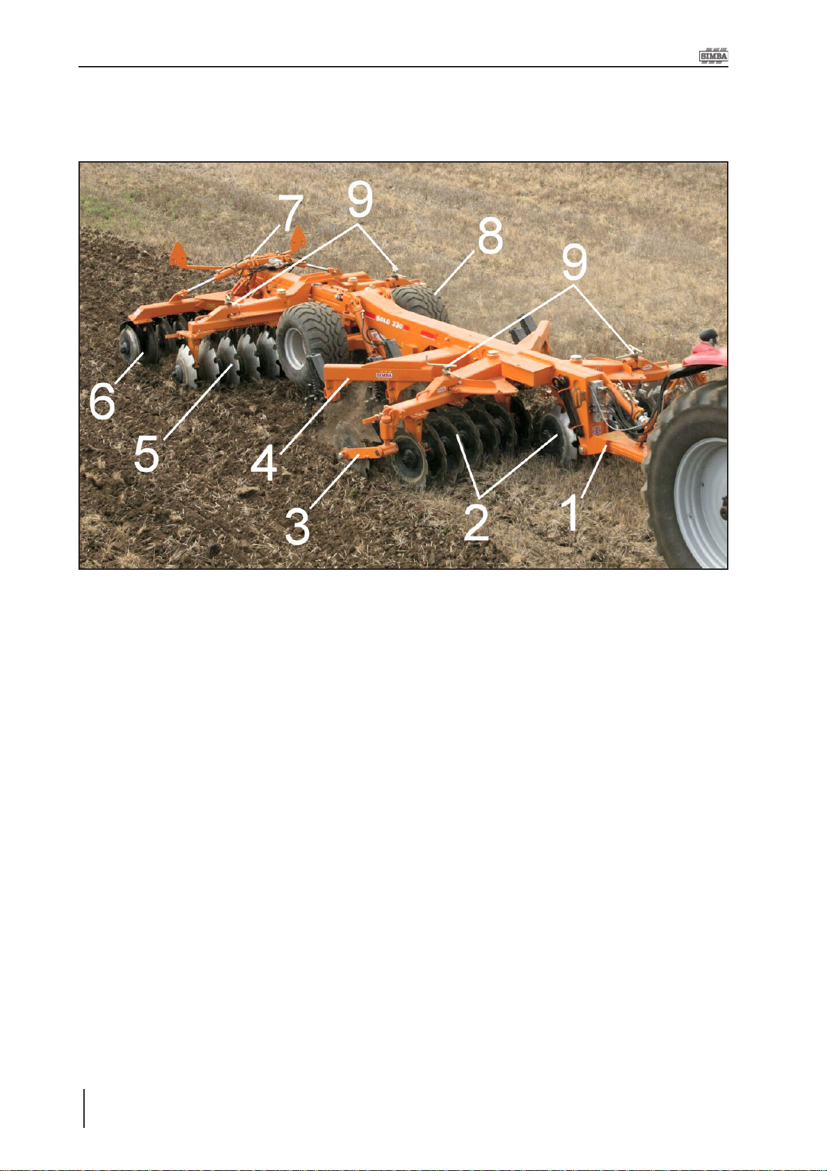
4. Adjustment / Operation
4. Adjustment/Operation
4.1 Description
Fig. 4.01: Simba Solo (Solo 330 ST R model shown)
1. Drawbar
2. Front Discs
3. Coulter Coverers
4. Tine Beam
5. Rear Discs
6. DD600 Roll
7. Roll Depth Adjuster
8. Transport Wheels
9. Disc Angle Locking Units
Solo
20
Operating Instructions
Page 21

4. Adjustment / Operation
The SIMBA Solo is an amalgamation of time
proven, successful Simba design
components brought together to form this
important development. The Solo has been
designed and produced in conjunction with
the Simba ECOtillage™ system to provide a
one pass mix with a fissured layer at disc
depth for through drainage and root access
to lower horizons. This enables rapid
drainage and access after rain, creating a
greater effective capacity for moisture
compared to ploughing for the same effective
total depth of cultivation.
In principle, the machine is a tandem disc with
trip reset Pro-Lift tines or Terra-Grip tines,
designed for low draft, high speed operations.
The addition of an integral roller ahead of the
rear gang, or a rear mounted roll, enables
more effective cultivation in one pass. The
leading set of disc blades cultivate the top
horizon, minimising clod formation and
reducing tine loadings and blockage. This
starts the ‘top down’ cultivation process,
retaining weathered tilth in the surface level
for stale seedbed purposes. The trip reset
tines follow the disc blades to shatter at depth
retaining the surface intact to work as an
ECOtillage
the problem of ‘wet years’ in non-plough
based terms. The key to the Solo’s success
is the lower draft tine point and wing which
maintain shatter across the full width of
cultivation. The mid/rear roll or trailing press
then consolidates the surface, cracks any
clods and firms the soil profile before/after the
rear gang completes mixing to depth. The
corrugated top and shattered lower horizons
are left fully weatherproof to any conditions
between cultivation and drilling whilst retaining
moisture below the surface for rapid straw
breakdown and optimum establishment of the
next crop.
™ stale seedbed. This eliminates
4.2 Solo Designations
Solo 380 ST R
123
1. This number refers to the working width
of the machine.
2. The ‘ST‘ stands for Shallow Tine. If a
machine is fitted with Terragrip tines it
is given this designation. If a machine
is fitted with hydraulic reset Pro-Lift tines
these letters will be absent from the
designation.
3. The ‘R‘ refers to the Rear roll format of
the machine. If no ‘R‘ is present in the
designation then the machine is set up
in the mid-roll format.
Examples:
Solo 380 ST - This is a 3.8m wide machine,
with Terragrip tines in the midroll configuration.
Solo 330 R - This is a 3.3m wide machine,
with hydralic trip-reset tines in
the rear roll configuration.
Operating Instructions
21Solo
Page 22
4. Adjustment / Operation
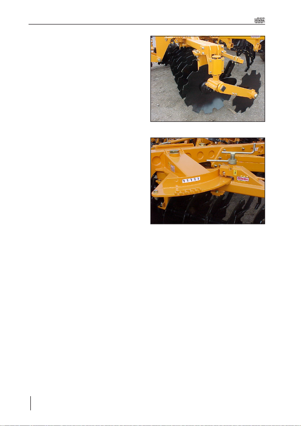
4.3 Disc Gangs
As with any disc combination the angle of the
disc gangs is dependant on the type of
operation being carried out in terms of the
degree of soil movement required. The nearer
the disc gang is to minumum angle, the lower
the degree of both soil movement and
penetration that will be achieved. The main
consideration once the discs are working is
to ensure that they are leaving a level surface
with no ridging or trenching either to the
outside or in the centre and are working with
equal effect across the width of each group
of gangs. In some cases it may be necessary
to replace the outer blade on the rear gangs
for one of a smaller diameter to return less
soil, thereby reducing any trough. It is
permissible to use the Coulter Coverer unit
without the scraper “knife” attached in
conditions where it may run clearer without it.
Fig. 4.02: Front Disc Gang
It is widely accepted through field experience
that a progressive discing effect will achieve
better results under normal circumstances
than a more aggressive approach.
Gang angling is set / altered using the pivoting
adjuster units. Ensure that the gang angles
are mirrored across the machine (for example
if the right hand front gang is set at “3” then
the left hand front gang should be set at “3”
also). Front to rear gang angles may differ
as required.
Position 1 on the gangs = minimum angle,
position 5 = maximum angle.
The Solo should be run level; the rear discs
are set lower and will work deeper than the
front.
Fig. 4.03: Disc Gang Angling / Locking
Solo
22
Operating Instructions
Page 23
4. Adjustment / Operation
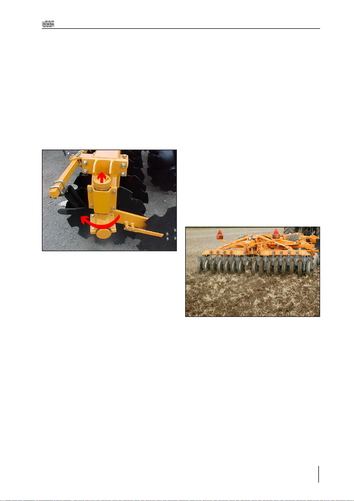
4.4 Coulter Coverer
The coulter coverers are located at the ends
of the front disc gangs. These units are
designed to stop the throw of soil beyond the
cultivating width of the machine. The coverer
on the right hand side of the machine has a
transport and work setting. To change
between the two, the collar should be lifted
and the coverer arm rotated. The collar can
then be lowered to lock the arm in position
(see Fig. 4.04 below).
4.5 Double Disc Roller
The standard DD600 roller is made up of
individual Double Disc (patented) Ring
segments.
The DD rings are designed to consolidate the
soil whilst cutting and crushing any clods.
Even in heavy, wet soils it can easily be
operated with minimal blockages occurring.
The rear DD roller carries a proportion of the
machine’s weight to ensure consolidation. It
also regulates the depth of the machine. The
corrugated surface left by the roller is
weatherproof both for wet or dry situations.
The DD roll can be positioned at the rear of
the machine (rear roll) or between the tine
beam and rear disc gang (mid-roll).
Fig. 4.04: RH Coulter Coverer (shown in transport
position).
Fig. 4.05: DD600 Roll
Operating Instructions
23Solo
Page 24
4. Adjustment / Operation
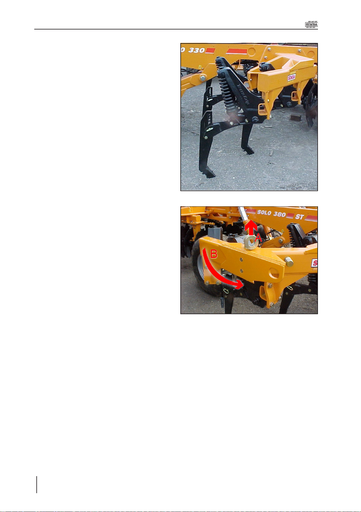
4.6 Terra-Grip Tines
Terra-Grip tines have a robust, basic
construction and are suitable for all soil types.
The spring-loaded auto-reset system with a
500kg trip force on each tine prevents
damage to the tines and tine brackets.
When the auto reset system is activated an
initial progressive phase holds the tine in the
ground in a steady position until the trip point
is reached. In the subsequent spring
compression phase the tine is raised gently
and rapidly to a maxmum height of 230mm.
The tines can be fitted with a selection of points
depending on application and have 6 depth
settings in 25mm increments.
Fig. 4.06: T erra-Grip Tines
The clip-on points are attached to the tine with
a quick release mechanism. A wedge
shaped bracket is bolted on to the tine and a
hammer is used to force the coulter on/off the
taper using the removal tool provided to
disengage the quick release system.
The quick release mechanism makes it
possible to change the points quickly and
easily without having to use any other tools.
The quick release system consists of a
wedge, plunger and a rubber spring.
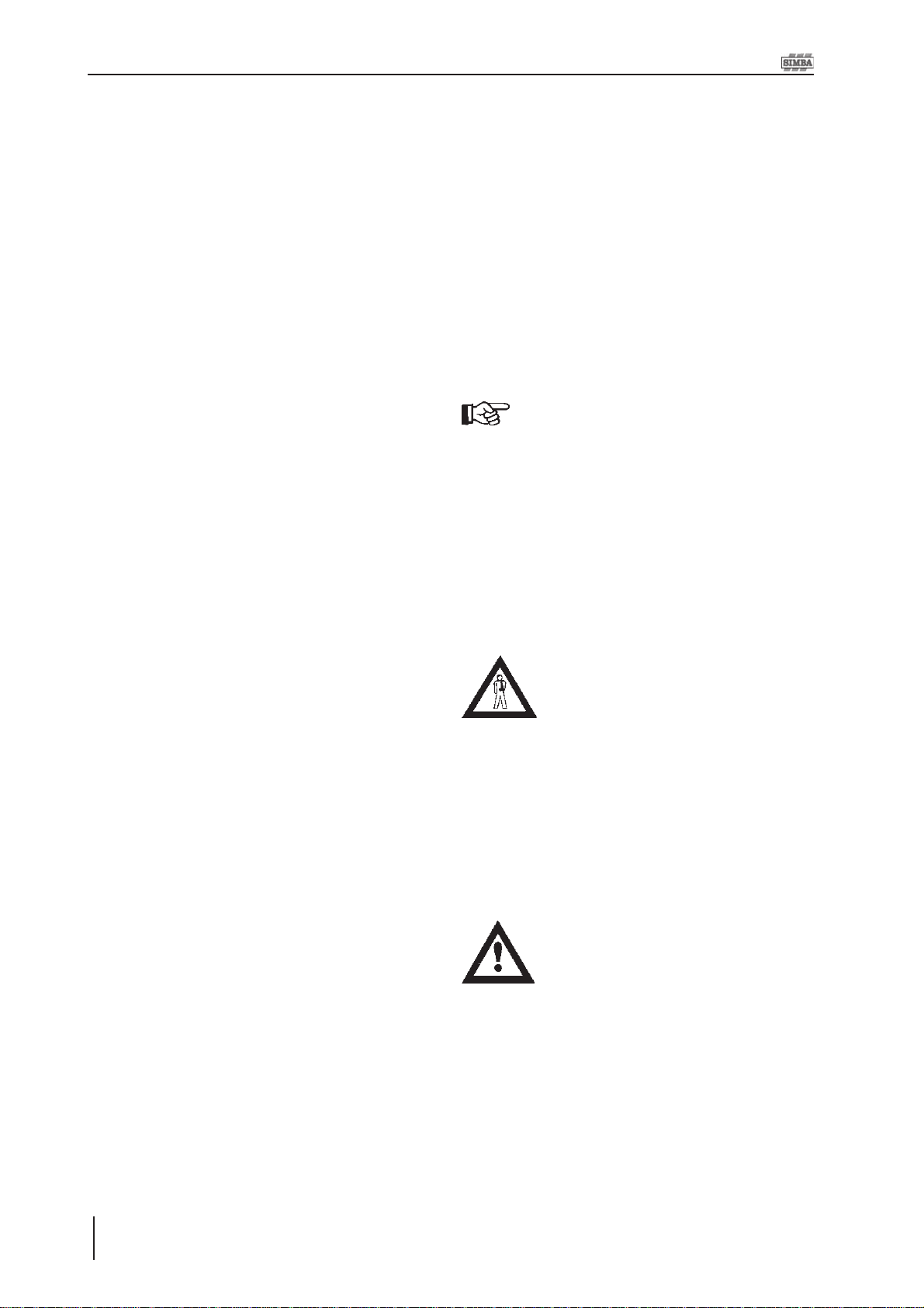
On 380 models the tine beam has two
settings, work and transport. In order to
change between the two remove the locking
handle (A on Fig. 4.07) and swing the gang
round (B). The locking handle can then be
wound onto the protruding bolt in order to
tighten the assembly for work.
Fig. 4.07: Folding Tine Beam on 380 Models
Solo
24
Operating Instructions
Page 25

4. Adjustment / Operation
4.7 Pro-Lift Tines
The arrangement of the toolbars in a ‘V’ frame
gives lower draught requirements and
maximises the loosening effect of each tine.
The depth of the subsurface tines can be
altered by moving the tines vertically relative
to disc depth in their respective clamps using
the 4 holes in the leg. Altering the drawbar
and lift circuit depth will also affect subsoiling
depth as well as discing depth.
Different wings are available to suit the soil
conditions and optimise the performance of
the machine.
It is important to set the machine up correctly
in order to achieve an efficient and worthwhile
operation. Although the Solo can work down
to around 350mm (14") this does not mean
that running at this depth is always worthwhile,
taking time to identify where there is a
problem in the soil profile and working to the
minimum depth required will save a lot of
otherwise wasted fuel and time. It is also very
important not to operate below the critical
depth of the tine, this is where the tine no
longer produces upward movement of soil
and effectively behaves as a mole plough,
therefore not producing the shattering effect
desired.
If the tines are operating below their critical
depth, this is indicated by a reduced
(minimal) heave/shattering effect coupled with
an extremely high draft requirement. Under
these circumstances either reduce tine depth,
increase the front disc depth to alleviate the
problem or change the type of wings.
4.8 Pro-Lift Wings
Standard Wing
P09060
• Maximum soil disturbance with
minimum draft requirement under normal
circumstances.
• Wing angle reduces wear rates on leg.
Extra Lift Wing
P10392
• Increased lift height and and rake angle
creates greater soil disturbance on all soil
types especially in moister conditions.
• Lower relative distance between edge
of wing and point reduces draft requirement.
• Has ability to work at lower depths with
no decrease in soil disturbance or risk of
smear.
• Effectively increases critical tine depth.
Extra Wide Wing
P10411
Pro-Lift tines are not available on
Solo 380 models.
• Improved lateral shatter in moist/wet
soils, or non-cohesive soils.
• Ideal for deep vegetable applications
under light/medium soils.
25Solo
Operating Instructions
Page 26

4. Adjustment / Operation
4.9 Work Settings
In work the wing cylinders should be fully
extended. A simple pressurised hydraulic
circuit automatically sets itself as the wings
are unfolded.
Optimum performance has been found to be
achieved when the press roll rings have worn
away the painted finish leaving a smooth shiny
surface. When the press roll rings are new or
rusty , soil may tend to pick up on the surface
and blockage may occur , this will reduce when
the rings are shiny again.
The Solo should be run with the chassis level
by extending the drawbar cylinder to the
necessary position and adding shims as
appropriate. In practice it is possible to use
the Solo on ground conditions that are
unsuitable to achieve the desired effect, and
it is usually possible to operate without regular
blockage under such unsuitable conditions,
assuming that the axles are tight and rings
smooth. As such, especially under wet
conditions, it is advisable to check on the
cultivation effect of the Solo.
General Rules when Setting
the Solo
• The drawbar cylinder setting and the roll
depth setting work on a 2:1 ratio. For
example; if 50mm of shims are added into
the drawbar cylinder then 25mm of shims
should be added into the roll depth control
rod in order to keep the machine level.
• The roll depth control rod works on a 1:1
ratio. If 25mm of shims are added into the
depth control rod this will result in the
machine running 25mm deeper.
Generally a forward speed of 5-7 mph (8-1 1
kph) will achieve optimum results, maximising
inversion and burial. Speeds in excess of
those stated above will tend to give a
deterioration in the quality of the work. This
may be seen as a ridge and trough effect
across the work surface due to soil being
thrown too far by the leading discs, the rear
discs then are unable to turn enough soil back.
In normal operation the machine should be
hydraulically drawn onto the drawbar shims,
however, it is permissibleto operate the lift
circuit in float in order to allow the implement
to follow contours as the tractor drawbar drops
(eg. over the brow of a hill).
Solo
26
Operating Instructions
Page 27

4. Adjustment / Operation
4.10 Starting Settings
This page details the recommended starting
settings for the Solo. These settings can then
be used as a base for further adjustment in
order to get the optimum performace from
your machine.
Ensure all settings from the left and right hand
sides of the machine mirror each other .
Disc Angles
Front Disc Gangs:
Drawbar Cylinder
Y ellow
1x
20mm
1x
Silver
51mm
Rear Disc Gangs:
Roll Depth
Red
1x
The drawbar cylinder shim settings are subject to the tractor
drawbar height. As such, the
shim settings shown above are
intended as a suggestion only .
The machine should be set to
run with the chassis level.
10mm
Tines
Pro-Lift Terra-Grip
1x
Black
29mm
Ä
Ä
27Solo
Operating Instructions
Page 28
4. Adjustment / Operation
4.11 Depth Control
Working depth can be set by mid or rear roll
and/or by transport wheels. Under normal
conditions the weight of the machine will be
carried on the roll and the drawbar of the
tractor , with the main lift wheels either fully up
or floating. Depth is set using the depth
control rod situated on the roll unit with shims
added and removed as appropriate. This is
achieved by raising the machine so that the
roll is clear of the ground and operating the
roll hydraulics until the wings just start to fold.
In this position it is possible for shims to be
added/removed from the depth control rod.
The roll can then be pressured back down and
the machine can continue to work. The front
to rear pitch of the machine should be
adjusted as appropriate to compensate for
changes in working depth by adjusting the
amount of shims on the drawbar cylinder.
Some conditions or finished effects may
dictate that depth control is carried out using
both the roll and the lift wheels.
4.12 Work Instructions
Driving speed
The Solo can be driven at speeds of up to 12
km/h.
This depends on the field conditions (type of
soil, surface trash, etc.).
Drive more slowly if the conditions are difficult
or a firmer finish is required.
Turning:
Before turning, the machine should
be eased out of work while driving.
Likewise, it should eased back into
work once the turn has been
completed.
4.13 Parking the machine
In order to avoid damage as a result of
moisture, the machine should be parked, if
possible, indoors or under cover .
With a Mid Roll / Rear Roll
Use roll depth adjuster/hydraulic cylinder to
set machine working depth - ensure wheels
are lifted clear of or just touching soil. Use
shims on drawbar cylinders to set chassis
pitch level. Machine can be run in float to
contour follow.
With the Transport Wheels
Use shims on lift cylinders to set machine
depth and shims on drawbar cylinders for
pitch. Balance the weight on wheels and roll
if they are to be used together for depth
control.
When manoeuvring the machine,
pay attention to your surroundings.
Ensure that nobody is in the
manoeuvring area (watch for
children!).
• Park the machine on level and solid ground.
• Raise the machine and remove shims from
the lift axle and drawbar cylinders.
• Lower the machine to the ground, ensuring
that it is stable.
When parking, ensure that no load
is carried by the T erra-Grip tines (if
fitted). This can lead to breakage
of the points.
• Remove the drawbar pin and drive forward
slowly until hitch is clear of tractor drawbar.
• Lower the drawbar to the ground.
• Switch off the tractor .
• Disconnect hydraulic lines from the tractor.
Solo
28
Operating Instructions
Page 29

4.14 Checks
The working quality depends on the
adjustments and checks made prior to and
during work, as well as on regular servicing
and maintenance of the machine.
Before beginning work it is therefore
important to carry out any necessary servicing
and to lubricate the machine as required.
Checks prior to, and during
work:
• Is the machine correctly hitched up and the
coupling device locked?
• Have the hydraulic lines been connected
according to the colour coding?
• Is the machine in a level operating position
and the working depth set correctly?
4. Adjustment / Operation
Working Elements
• Are the discs and other cultivation tools in a
serviceable condition?
• Are the scrapers still operable, so that the
rolls do not jam?
Operating Instructions
29Solo
Page 30

5. Servicing and Maintenance
5. Servicing and
Maintenance
Follow the safety instructions for
servicing and maintenance.
5.1 Servicing
Your machine has been designed and
constructed for maximum performance,
operational efficiency and operator
friendliness under a wide variety of operating
conditions.
Prior to delivery, your machine has been
checked at the factory and by your authorised
dealer to ensure that you receive a machine
in optimum condition.
To ensure trouble-free operation, it
is important that servicing and
maintenance work is performed at
the recommended intervals.
5.2 Cleaning
In order to ensure that the machine is always
in operating condition and to achieve
optimum performance, perform the cleaning
and servicing work at regular intervals.
Avoid cleaning the roll / disc bearings with a
high- pressure hose or a direct water jet. The
housing, screwed connections and ball
bearings are not watertight.
5.3 Tightening Disc Axles
1. Loosen the bearing mounting bolts on
one pillar. This is to allow the bearing
to move slightly when tightening the
axle. This ensures that the bearings are
not preloaded, which could lead to early
failure.
When the axle needs tightening
again, loosen the bearing that was
not loosened the previous time.
2. Undo and remove the locking plate bolt
and plate.
3. Loosen axle slightly and spin discs
relative to each other / spools and
bearings.
4. Fit one of the disc axle spanners onto
the nut at the opposite end of the gang
that is being tightened. The spanner
should be jammed onto the ground to
prevent it from slipping when the axle
is tightened. Ensure the security of this
spanner is maintained as the axle is
tightened / loosened. Injury can occur if
this spanner is unattended and slips
free,
5. Tighten the axle. Continue to tighten the
axle until the locking plate can be
refitted. DO NOT back the nut off to allow
the plate to be fitted.
6. Refit and tighten the locking plate bolt.
7. Tighten the bearing bolts.
Solo
30
Operating Instructions
5.4 Terra-Grip Tine Beams
A pair of shims located within the tine beam
on 380 models are there to retain the
tightness while the machine is in the work
position. These shims create a fulcrum which,
when the lock bolt is tightened, locks the the
wing securely in position by removing
clearances in the pivot. The amount of shims
can be varied to give a gap of 2-3mm at the
point indicated in Fig. 5.02 before tightening
the lock bolt (which will close the gap).
Page 31

Fig. 5.01: Inner Tine Beam Shims
5. Servicing and Maintenance
Do not attempt to assist fitting tine
point with a steel headed hammer ,
as this can lead to splintering of the
metal due to its hardness, which
can cause injury. If tine fitting
requires assistance, a copper/hide
mallet should be used. Goggles
should be worn.
5.7 Double Disc Axles
The axles on this roller are tensioned by the
main axle through the centre of the rings and
bearings.
Specialist equipment is required
for the disassembly of Double Disc
axles. Please consult your dealer
under any circumstances that
require disassembly of these
axles.
Fig. 5.02: Tightening the Tine Beam
5.5 Terra-Grip Tine Points
When changing points on Terra-
Grip tines extreme care should be
taken. Wear goggles at all times
when changing tine points.
5.6 Pro-Lift Tines
When fitting new tine points, ensure all rough
or square edges on the mating faces of the
legs are removed prior to fitting the new tips
(if necessary).
REMOVE SQUARE/ROUGH EDGES
BEFORE ATTACHI NG TINE POINT
Maintenance of these rollers is limited to daily
greasing of the bearings to flush out dirt, and
regular inspection to ensure the assemblies
are tight, and scrapers are correctly set. The
axles can be tightened provided the bearing
pillar ‘U’ bolts are loosened to avoid
preloading the bearings as they move
sideways to each other. Ensure the bearing
pillars are re- tightened to the mainframe after
this.
5.8 Roll Wing Shims
A set of shims are located on the ends of the
wings. These can be added to / subtracted
from in order to ensure that the roll runs level
when pressured down in work.
Fig. 5.03: Fitting Pro-Lift Tine Points
Fig. 5.04: Roll Wing Shims
31Solo
Operating Instructions
Page 32

5. Servicing and Maintenance
5.9 Hydraulics
A low oil flow should be used, i.e.,
tractor tickover or low flow
selected.
The wing circuit is controlled by an
overcentre valve contained within
the manifold block which positively
locks oil flow until pressurised by
the tractor. System pressure can
be retained in the circuit even after
depressurisation of the tractor
quick release couplings.
Exercise extreme care when
checking the valve or circuits, and
under no circumstances attempt
to adjust or loosen fittings without
prior reference to your authorised
simba dealer, and detailed
maintenance instructions.
5.9.1 Drawbar & Axle
Phasing
The following procedure allows a greater
degree of control when raising/lowering and
levelling the machine (front to rear). For
minimum heat build up in hydraulic fittings
(due to raised oil temperatures through the
restricted fittings) the tractor flow rate should
be set in it’s lowest setting.
The restrictor A in Fig. 5.05 can be used
to slow oil from the drawbar cylinder when
raising the machine.
The restrictor B in Fig. 5.05 can be used
to slow oil from the axle cylinder when
lowering the machine.
A combination of the restriction instructions
above should be used to raise and lower
approximately parallel to the ground.
Solo
32
Operating Instructions
Fig. 5.05: Drawbar & Axle Phasing
Page 33

5. Servicing and Maintenance
5.9.2 Pro-Lift Trip-Reset
Tine Hydraulics
Fig. 5.06: Pro-Lift Tine Hydraulic Manifold
The circuit allows for the tines to be
pressurised down into work, whereupon a
relief valve limits this applied tractor down
pressure to a value less than the main system
accumulator (80b x 2 litre). This allows tines
to trip in work, the oil being absorbed by the
main accumulator. A secondary (rod side)
accumulator ensures this side of the cylinder
is maintained full of oil to minimise cavitation
and seal damage. A pre charge valve restricts
return rod side oil flow to the tractor as the
tines are pressurised down to ensure this
secondary circuit is charged.
In operation, oil is locked in the cylinder circuit
at a pressure determined by the relief valves
90-120 bar full bore side and 20 to 60 bar
rod side. This occurs at all times, even with
the circuit in float at the tractor, provided the
tines are fully down. For extremely stony
conditions, adjust the valve to read 90 bar on
the gauge as the tines are pressured down.
For heavy soils with little stone where
compaction is present it is possible to
increase this pressure to 120 bar.
If the tine circuit should need setting the following procedure should be followed (an assistant will be required):
1 First locate the manifold block; it is lo-
cated on the left hand side of the machine attached to the main chassis, just
behind the wing that supports the trip
reset tines.
2 With the valve block directly in front of
you, undo the lock nut on the valve on
the top face of the block. Using a 4mm
allen key turn the valve all the way clockwise, then turn it anticlockwise 2 full
turns.
3 Locate the valve on the front face of the
block (the one facing the rear of the tractor) and undo the lock nut then turn the
valve all the way clockwise.
4 Locate the valve on the rear face of the
block (facing the rear of the machine)
and undo the lock nut then turn the valve
all the way anticlockwise.
5 S tart the tractor and put the spool lever
that controls the tines in to the float position. Both the gauges will go to zero
and the tines will go down. This indicates that system is depressurised.
6 Now get your assistant to pressure the
tines down. Whilst they are being pressured down, turn the valve on the rear
face of the block slowly clockwise. The
pressure on the lower gauge will start
to rise. Turn the valve until you reach
approximately 80 to 90 bar (the pressure on the upper gauge will now be
reading approximately 10 to 15 bar).
Lock off all the valves. The tine circuit
is now set.
Operating Instructions
33Solo
Page 34

5. Servicing and Maintenance
5.9.3 2 Litre Accumulators
The manufacturers of this part recommend
that the pressure of the nitrogen pre-charge
is checked annually (seasonally). The
recognised procedure for testing the nitrogen
pressure uses specialised test equipment. In
instances where this equipment is not
available the following procedure should be
used.
1. Attach the Solo 330 to a tractor and
attach the lift and tine circuits.
2. Raise the machine clear of a firm
surface. Function the tine circuit, noting
the pressures registered on the gauges
when the tines are pressured down. The
following settings are normal.
Soil Type S e tting Cyl. Ga uge Rod Gauge
Normal 90 bar 20-40 bar
Hard / St one Free 120 bar 40-60 bar
It is important that this procedure is carried
out to avoid damage to the machine. In a
situation where nitrogen pressure has
dropped there will be no indication in normal
work as the void usually filled with nitrogen
will become filled with oil and the gauges will
register no change in working pressure.
Fig. 5.07: 2 Litre Acumulator
3. Remove three tines from the machine
leaving one of the inner tines in the
deepest work setting.
4. Lower the machine carefully. The aim
is to cause the remaining tine to trip and
note the change in cylinder gauge
pressure. The cylinder gauge should
show a rise indicated in the table below .
Soil Type S etting
Normal 90 bar 1 5-20 bar
Hard / St one Free 120 bar 35-40 bar
Starting Cyl.
Pressure
Pressure
Rise
5. If less than full tine trip is achieved or a
pressure rise of greater than 55 bar is
indicated then the 2 litre accumulator
should be recharged to 80 bar nitrogen
pressure or replaced with a correctly
charged accumulator .
Solo
34
Operating Instructions
Page 35

5. Servicing and Maintenance
V
5.9.4 Roll Hydraulics
Tampering with a pressurised
hydraulic system is extremely
dangerous.
Pressure may be retained in the
roll circuit between the valve and
the cylinders. Although it shouldn’t
be necessary to remove the fittings
between the valve and the
cylinders, the de-pressurisation
procedure should be followed
before doing so.
De-pressurisation Procedure
for Roll Hydraulics
To de-pressurise the circuit, identify and
adjust the following valves on the roll valve
block.
All valves can be identified by stamped codes
adjacent to each valve.
Roll Hydraulics Setting
Procedure - Factory settings
The following table outlines the re-setting of
the roll hydraulics back to factory settings.
Each number below corresponds to the
relevant valve on the hydraulic block located
near the roll section of the machine.
alve # Function Setting Procedure
1 Over Centre Valve
for locking w ings
down in work
2 Over Centre Valve
for holding wings
safely d uring
unfolding
Adjust the valve all the way
out (an ti-clockwise) th en a
half turn in (clockwise).
Adjust the valve all the way
anti-clockwise then check
by unfolding the wings to a
45° an gl e and pu tting the
hydraulics into float. The
wings will now be locked.
Slowly turn the va lve
clockwise until the wings
start to lower. At this point
stop t he wings lowering by
slowly turning the valve anticlockwise. When the wings
have stopped lowering turn
the valve one full turn anticlockwise and lock it off.
1. Set tractor hydraulics to neutral,
machine lowered and unfolded.
2. Adjust Over Centre valve (1) fully
clockwise.
3. Adjust Over Centre valve (2) fully
clockwise.
4. Set main system to float, or allow oil
pressure to be released in both
directions.
The manifold may need depressurising after being subjected to
high oil flow.
3 Relief Valve -
Unfolding
4 Relief Valve -
Folding
Set to 80 bar
Set to 150 ba r
35Solo
Operating Instructions
Page 36

5. Servicing and Maintenance
5.10 Changing Roll
Configuration
The following procedures outline changing the
configuration of the roll from the mid mounted
position to the rear position and vice versa.
Extreme care should be exercised
while performing this operation and
all Health & Safety guidelines
present in this manual should be
adhered to.
Mid-Roll to Rear Roll
1. Unfold the press unit (all other working
elements should remain in the transport
position).
2. Remove the depth control rod and the
shim storage tie rod (items 17&19 on
Page 128).
3. Put the wing circuit into float .
4. Remove the 6 nuts on the rampoint unit
and the 2 outer cylinder bolts.
5. Disconnect the hydraulic hose on the
valve block (at ports F01 & FI1) and at
the junction in the pipes. Remove and
stow this hose (in the toolbox).
Pressure may be retained in the
circuit between the valve and the
cylinders. Although it shouldn’t be
necessary to remove the fittings
between the valve and the
cylinders, the de-pressurisation
procedure (page 35) should be
followed before doing so.
6. Remove the bolts from the lift cylinders
on the carriage unit and lower the roll
unit to the ground.
7. Fully raise the machine and put the
maximum amount of shims into the lift
axle rams.
8. Open the drawbar taps and lower the
machine until the front gangs are just
clear of the ground so that the rear
gangs can clear the roll unit.
9. Drive the machine forward until the back
gang is clear of the roll unit.
10. Raise the machine, take out the lift axle
shims before lowering the machine
again.
11. Remove the 4 bolts on the rear gang
mounting unit (as seen on Page 86).
12. Close the drawbar cylinder taps.
13. Carefully raise the machine until the
gang unit is clear of the mounting plate.
14. Reverse the machine through the rear
gang hole and bolt the rear gang and
chassis support (see Page 76) loosely
into position.
15. Raise the machine and place the rear
gangs into the minimum angle setting.
16. Remove the rear drawbar .
17. Remove wear pads for the roll carriage
from the mid-mount position to the rear
position (item 31 on Page 66).
18. Raise the roll carriage unit to the
mounting plate at the back of the
machine and attach along with chassis
support unit. Tighten the bolt s left loose
in 14.
19. Re-insert the depth rod and the shim
storage bar.
20. Bolt on the top cylinder plate.
21. Lift the carriage unit and attach the rams
to the top.
22. Re-route hoses as per revised piping
for mid/rear roll configuration. Utilise the
the hoses that were not removed
(P13639 (3/8" 1650mm long)). Take
care whilstreconnecting the hoses to
the valve to put the twin cable-tied hose
into port F01 (rod side) and the single
cable-tied hose into port FI1 (cylinder
side).
Solo
36
Operating Instructions
Page 37

5. Servicing and Maintenance
Rear Roll to Mid Roll
1. Unfold the press unit (all other working
elements should remain in the transport
position).
2. Remove the depth control rod and the
shim storage tie rod (items 17&19 on
Page 128).
3. Put the wing circuit into float.
4. Remove the 6 nuts on the rampoint unit
and the 2 outer rampoint bolts (fold
cylinders).
5. Disconnect the hydraulic hoses on the
valve block (at ports F01 & FI1).
Pressure may be retained in the
circuit between the valve and the
cylinders. Although it shouldn’t be
necessary to remove the fittings
between the valve and the
cylinders, the de-pressurisation
procedure (page 35) should be
followed before doing so.
7. Remove the bolts from the lift (rotate)
cylinders on the carriage unit and lower
the upper roll carriageunit to the ground.
8. Remove the chassis support unit and
reattach the disc gang for safety .
9. Remove the remaining (rear) lower roll
carriage bolts and lower the roll to the
ground.
10. Remove wear pads for the roll carriage
from the rear position to the mid-mount
position (item 31 on Page 66).
11. Remove the bolts on the rear gang
mounting unit (as seen on Page 86).
12. Close the drawbar cylinder taps.
13. Carefully raise the machine until the
gang unit is clear of the mounting plate.
14. Drive forwards so the machine passes
through the rear gang hole and bolt into
position.
15. Raise the machine and place the rear
gangs into the transport angle setting.
16. Fully raise the machine and put the
maximum amount of shims into the lift
axle rams.
17. Open the drawbar taps and lower the
machine until the front gangs are just
clear of the ground so that the rear
gangs can clear the roll unit.
18. Reverse the machine until the back
gang is clear of the roll unit.
19. Raise the machine, take out the lift axle
shims before lowering the machine
again.
20. Raise the roll carriage unit to the
mounting plate at the mid-mount
position of the machine.
21. Re-insert the depth rod and the shim
storage bar .
22. Bolt on the top cylinder plate.
23. Lift the carriage unit and attach the rams
to the top.
24. Re-route hoses as per revised piping
for mid/rear roll configuration. Utilise the
the hoses from the toolbox (P13640 (3/
8" 1450mm long)) between the junction
and the valve to bridge the gap. Take
care whilst reconnecting the hoses to
the valve to put the twin cable-tied
hose into port F01 (rod side) and the
single cable-tied hose into port FI1
(cylinder side).
25. Fit the rear drawbar (see page 70).
Operating Instructions
37Solo
Page 38

5. Servicing and Maintenance
5.11 Preparation for
Storage
If you need to store the machine for a longer
period, observe the following points:
• Park the machine undercover if possible.
• Protect the roll / discs against rust. If you
need to spray the implements with oil, use
light biologically degradable oils, e.g. rape
oil.
Cover any rubber sections before
using oil sprays. These sections
must not be oiled.
Remove any traces of oil with a
suitable cleaning agent.
5.12 Operator Support
If you have a problem, please contact your
dealer. They will endeavour to solve any
problems which may occur and provide you
with support at all times.
In order to enable your dealer to deal with
problems as quickly as possible, it helps if
you can provide them with the following data.
Always state the:
5.13 Maintenance
Intervals
Apart from daily maintenance, the
maintenance intervals are based on the
number of operating hours and time data.
Keep a record of your operating hours to
ensure that the specified maintenance
intervals are adhered to as closely as
possible.
Never use a machine that is due for
maintenance. Ensure that all deficiencies
found during regular checks are remedied
immediately.
Avoid sharp-edged and pointed
parts (disc blades, etc.) when
working on the machine.
Place the machine on suitable
supports when working
underneath! Do not work under a
machine which is not supported!
• Customer Number
• Name and Address
• Machine Model
• Serial Number of Machine
• Date of Purchase and Operating Hours
• T ype of Problem
Solo
38
Operating Instructions
Page 39

5.14 Maintenance Overview
5. Servicing and Maintenance
--- ---
Solo 330/380 Maintenance O verview
Remove caps & tighten nuts, then back off the nut one flat to
ensure smooth operation. Replace cap
Af ter f irst operati on Instructi o ns Interval Note
Check all screw, bolt and plug connections Check they are firmly seated. Tighten / Secure if necessary --- ---
Check wheel studs for tightness Check on delivery and before transporting the machine --- ---
Dur ing operation
Lubricate machine See overview of lubricating points --- Page 40
Lubricate machine See overview of lubricating points --- Page 40
Wheel studs Check tightness before transporting the machine daily ---
Disc Angle Locks, Working Depth Check setting and ensure they are firmly secured daily Page 24
Hydraulic system and components Check seals, signs of crushing/wear, function and condition daily Page 32
Disc Axle Bearings Check condition, mountings and smooth operation daily Pages 22, 30
Roll Axle bearings Check condition, mountings and smooth operation daily Pages 23, 31
Double Disc roller ring segments Check condition and ensure they are firmly secured daily Pages 22, 30
Af ter season
Safety devices (Transport Pins) Check condition and function daily ---
Lubricate machine See overview of lubricating points --- Page 40
Bolts / Lock Bolts Grease any exposed threads --- ---
Af ter 4 years
Gang pivots
Entire machine Carry out cleaning and maintenance --- ---
Hydraulic pipes Replace MRL Anh I EN 1533
Spray Double Disc roll with oil Use biological oil if possible - cover rubber elements --- ---
39Solo
Operating Instructions
Page 40

5. Servicing and Maintenance
5.15 Overview of Lubricating Points
Solo lubr ication po ints In terval Diag. No.
DD Roll Bearings Daily 5.08
Disc Bearings Daily 5.09
Coulter Coverers Daily 5.10
Gang Pivots 50 Hours 5.11
Pro-Lift Time Arms 50 Hours 5.12
Disc Angle Locking Handles 50 Hours 5.13
Wheel Bearings 50 Hours 5.14
Transport Axle Pivot 50 Hours 5.15
Roll Carriage Pivot 50 Hours 5.16
Wing Pivots 50 Hours 5.17
Drawbar Pivot 50 Hours 5.18
Fig. 5.08: DD Roll Grease Points Fig. 5.09: Disc Axle Grease Points
Fig. 5.10: Coulter Coverer Grease Points
Fig. 5.1 1: Gang Pivot Grease Points
Solo
40
Operating Instructions
Page 41

5. Servicing and Maintenance
Fig. 5.12: Pro-Lift Tine Arm Grease Points
Fig. 5.14: Wheel Hub Grease Points Fig. 5.15: Transport Axle Pivot Grease Point
Fig. 5.13: Disc Angle Lock Grease Points
Fig. 5.16: Roll Carriage Pivot Grease Points
Fig. 5.18: Drawbar Pivot Grease Point
Fig. 5.17: Wing Pivot Grease Points
41Solo
Operating Instructions
Page 42

5. Servicing and Maintenance
5.16 Lubricating the
Machine
Please read the section entitled "Using
Lubricants" carefully before lubricating the
machine.
The machine must be lubricated regularly in
order for it to remain serviceable. Regular
lubrication also contributes towards extending
the service life of your machine.
The recommended lubricating intervals are
specified in "Inspection" and "Maintenance
Intervals".
After it has been washed using a highpressure hose or steam cleaned, the machine
should always be lubricated using a grease
gun. Ensure that the universal joints and
splined shafts are lubricated regularly .
5.17 Handling of
Lubricants
Always exercise extreme care and observe
the recommended hygiene rules when
handling mineral oil products. Details of these
handling regulations can be found in
information provided by the health authorities.
Storage and Handling
• Always store lubricants where they cannot be
accessed by children.
• Never store lubricants in open or unlabelled
containers.
Fresh Oil
• A part from taking the usual care and observing hygiene rules, there is no need to take
any special precautions when handling fresh
oil.
Waste Oil
• Waste oil can contain harmful cont aminants
which may cause skin cancer, allergies and
other illnesses.
Please ensure that you read the following
instructions as well as the relevant
information. This also applies to any of your
employees who handle lubricants.
Hygiene
Lubricants do not present a health hazard
provided they are used for their specified
purpose.
In the case of prolonged skin contact,
lubricants - especially low-viscosity oils - may
remove the natural layer of fat contained in
the skin, resulting in dryness and possible
irritation .
It is important to take extreme care when
handling waste oil as it may contain other
irritants.
V apours given off by cleaning agents and oils
are also a potential health hazard.
Y ou should therefore not carry any oily cloths
around. Change soiled work clothing as soon
as possible.
Attention!
Oil is a toxic substance. Should you swallow
any oil, do not try to vomit. Contact a doctor
immediately.
Protect your hands with barrier cream or wear
gloves to avoid contact with the skin. Wash
off any traces of oil thoroughly with soap and
hot water .
• Wash your skin thoroughly with soap and water.
• Use special cleaning agents to clean any
dirt off your hands.
• Never wash oil residue from your skin with
petrol, diesel fuel or paraffin.
• A void skin contact with any oily clothing.
• Do not keep any oily rags in your pockets.
• Wash soiled clothing before wearing it
again.
• Ensure that any oily footwear is disposed of in
the proper manner .
Solo
42
Operating Instructions
Page 43

5. Servicing and Maintenance
Measures in case of injury
through oil
Eyes:
Should any oil be splashed into your eyes,
rinse with water for 15 minutes. If the eye is
still irritated, contact a doctor immediately
If oil is swallowed
If oil is swallowed, it is important not to induce
vomiting. Contact a doctor immediately .
Skin irritation caused by oil
In case of prolonged skin contact, wash off
the oil with soap and water.
Oil Spills
Use either sand or a suitable granular
absorbent to soak up any spilt oil. Dispose of
the oil-contaminated absorbent in the proper
manner.
5.18 Lubricants &
Hydraulic Oil
Hydraulic System
The hydraulic fluid from the tractor is mixed
with the hydraulic fluid from the machine.
The supplied machine hydraulic system
contains T ot al AZOLLA ZS 32 oil.
Lubricants
All lubricating points on the machine can be
lubricated with multigrade lubricating grease
as specified in DIN 51825 KP/2K - 40.
Oil Fires
Never use water to extinguish an oil fire. The
oil will float on the water causing the fire to
spread.
Burning oil/lubricant must be extinguished
using a carbon dioxide powder or foam
extinguisher. Always wear respiratory
equipment when dealing with fires of this type.
Waste Oil Disposal
Oil-contaminated waste and used oil must be
disposed of in accordance with current
legislation.
Waste oil must be collected and disposed of
in accordance with local regulations. Never
pour used oil into unsealed sewage systems
or drains or onto the ground.
Operating Instructions
43Solo
Page 44

6. Faults and Remedies
6. Faults and Remedies
Solo 330/380 Trou bl eshooti ng
Fault Possible cau s e Remedy
Machine pulls t o one side Discs set unevenly Adjust each pair of disc gangs
Tines set un evenl y Adjust t ine depth
Rol l blocked Unblock roll
Machine not running level
front to rear (if not
deliberate)
Tr ansport w heels fail t o
lift machine
Discs fail to penetrate More dept h needed Adjust dept h cont r ol
Disc gang un even
wor king depth side to
side
Machine pullin g up clods Chassis r unn in g nose down Add shims t o dr aw bar cylinder
Mach ine set in cor r ect ly
Tr actor r el ief valve operat in g
tr act or hydraulics worn
Gang angle too lit t l e
Blades wor n Repl ace bl ades
Adju st drawbar shims to
compensate or if n ose diving
decrease mid/ r ear r ol l pr essure.
Decrease fl ow rate
Check gang settin gs and
incr ease gang angle if
appropriate
Adjust dept h contr ol u nit on r oll /
sh ims in drawbar cylinder s
Rear disc dragging u p
wet soil
Ridge is for m ed bet w een
gan gs in wor k
Trou gh is for med
betw een gangs in w or k
Solo
44
Operating Instructions
Chassis runn ing tail low
Gang an gl e too sev er e
Speed too h igh Adjust f or ward speed
Gang angle too lit t l e
Speed too l ow Adjust forw ar d speed
Rem ove shims f rom dr awbar
cylinder
Adjust gang angl e and / or
operat in g dept h
Adjust gang angl e and / or
operat in g dept h
Page 45

7. Par ts & Assembl y
Table of contents
7. Parts & Assembly
General Assembly ...................... 4 6
330 Pro-Lift Mid-Roll Full Assembly .........46
330 Pro-Lift Rear-Roll Full Assembly .......48
330 ST - 5 Tine Mid-Roll Full Assembly....50
330 ST - 5 T ine Rear-Roll Full Assembly..52
330 ST - 7 Tine Mid-Roll Full Assembly....54
330 ST - 7 T ine Rear-Roll Full Assembly..56
380 ST - 7 Tine Mid-Roll Full Assembly....58
380 ST - 7 T ine Rear-Roll Full Assembly..60
380 ST - 9 Tine Mid-Roll Full Assembly....62
380 ST - 9 T ine Rear-Roll Full Assembly..64
Chassis Assembly...................................66
Drawbar Assembly..................................68
Rear Drawbar Assembly .........................70
Lift Axle Assembly ...................................72
Light Mounting Assembly.........................74
Chassis Support Assembly .....................76
Disc Gangs & Axles ....................78
330 Front RH Disc Gang Assembly.........78
330 Front LH Disc Gang Assembly .........80
380 Front RH Disc Gang Assembly.........82
380 Front LH Disc Gang Assembly .........84
Rear Gang Carrier Assembly ..................86
330 Rear RH Disc Gang Assembly .........88
330 Rear LH Disc Gang Assembly..........90
380 Rear RH Disc Gang Assembly .........92
380 Rear LH Disc Gang Assembly..........94
Coulter Coverer RH Assembly.................96
Coulter Coverer LH Assembly .................98
7 Blade Front Disc Axle.........................100
8 Blade Front Disc Axle.........................102
7 Blade Rear Disc Axle .........................104
8 Blade Rear Disc Axle .........................106
Series 2 Bearing Assembly...................108
Double Disc Roll..................... 128
Roll Carriage Assembly ....................... 128
330 RH Roll Wing Assembly................. 130
330 LH Roll Wing Assembly ................. 132
380 RH Roll Wing Assembly................. 134
380 LH Roll Wing Assembly ................. 136
330 RH Roll Unit Assembly................... 138
330 LH Roll Unit Assembly................... 140
380 RH Roll Unit Assembly................... 142
380 LH Roll Unit Assembly................... 144
Double Disc Axle Assembly 8 Rings ..... 14 6
Double Disc Axle Assembly 9 Rings ..... 14 8
Double Disc Pillar Assembly ................ 150
Following Har row (optional) ........... 152
330 Following Harrow RH................... 15 2
330 Following Harrow LH ................... 154
380 Following Harrow RH................... 15 6
380 Following Harrow LH ................... 158
Hydraulics.............................. 160
Lift Circuit Components...................... 160
Lift Circuit........................................... 162
Wing Circuit Components .................. 164
Wing Circuit ....................................... 166
Pro-Lift T ine Circuit Components........ 168
Pro-Lift Tine Circuit ............................ 170
Pro-Lift Tines ........................... 11 0
Pro-Lift Tine Beam Assembly ................110
Pro-Lift Tine Arm Assembly ................... 112
Pro-Lift Tine Assembly .......................... 114
Terra-Grip Tines ...................... 11 6
330 ST - 5 T ine Frame Assembly .......... 116
330 ST - 7 T ine Frame Assembly .......... 118
380 ST - 7 T ine Frame Assembly ..........120
380 ST - 9 T ine Frame Assembly ..........122
T erra-Grip Centre T ine Assembly...........124
T erra-Grip Tine Assembly ......................126
45Solo
Operating Instructions
Page 46

7. Parts & Assembly
PJG
AAS2275
21/11/2005
SOLO 330 PROLIFT
SOLO 330 PROLIFT FULL ASSEMBLY - MID ROLL FORMAT
Solo
46
Operating Instructions
Page 47

7. Parts & Assembly
AS2275
S O LO 3 3 0 P ROLIF T F ULL AS SEMBLY -
MID ROLL FORMAT
ITEM PART NO DESCRIPTION QTY COMMENTS
1
2
3
4
5
6
7
8
9
10
11
12
13
14
15
16
17
18
19
20
21
22
23
24
25
26
27
28
29
30
31
32
33
34
35
36
37
38
39
40
41
42
43
44
45
46
47
48
49
50
AS228 6 CHASSIS ASSEMBLY 1
AS228 5 DRAWBAR ASSEMBLY 1
AS228 9 REAR GANG CARRIER ASSEMBL Y 1
AS2291 LIGHT MOUNT ASSEMBLY 1
AS229 0 ROLL C ARRIAG E ASSEMBLY 1
AS230 4 PROLI F T TINE BEAM ASSEMBLY - HYD. TRIP 1
AS229 4 FRONT GANG ASSEMBLY RH 1
AS229 5 GANG ASSEMBLY FRONT LH 1
AS228 8 LIFT AX L E ASSEMBL Y 1
AS229 8 REAR GANG ASSEMBLY RH 1
AS229 9 GANG ASSMEBLY REAR LH 1
AS230 9 ROLL WI NG ASSEMBLY RH 1
AS231 0 ROLL WI NG ASSEMBLY L H 1
AS2 328 LIFT CI RCUIT - HY DRAULIC COMPO NE NTS 1
AS2 330 FOLDING RO LL C IRCUI T - HYDRAULI C COM P O NE NTS 1
AS229 2 REAR DRAWBAR ASSEMBLY 1
AS2420 DD600 ROLL UNIT RH 1
AS2419 DD600 ROLL UNIT LH 1
Operating Instructions
47Solo
Page 48

7. Parts & Assembly
AAS2276
PJG
21/11/2005
SOLO 330 PROLIFT
Solo
48
Operating Instructions
SOLO 330 PROLIFT FULL ASSEMBLY - MID ROLL FORMAT
Page 49

7. Parts & Assembly
AS2276
SOLO 330 PR OLIFT R EAR ROLL FORMAT FU LL
ASSE MBLY
IT EM PART N O D ESCRIPT ION QTY COMMENT S
1
2
3
4
5
6
7
8
9
10
11
12
13
14
15
16
17
18
19
20
21
22
23
24
25
26
27
28
29
30
31
32
33
34
35
36
37
38
39
40
41
42
43
44
45
46
47
48
49
50
AS22 86 CHASSIS ASS EMBLY 1
AS22 85 DRAWBAR ASSEMBLY 1
AS22 89 REAR GANG CARRI ER ASSEMBLY 1
AS22 9 1 LI G HT MOUNT ASSEMBLY 1
AS22 90 ROLL C ARRI AGE ASSEM BLY 1
AS23 04 PROLI FT TINE BEAM ASSE MBLY - HYD. TRIP 1
AS22 94 FRONT GANG ASSEMBL Y RH 1
AS22 95 GANG ASSEMBL Y FRO NT LH 1
AS22 8 8 LI FT AX L E ASSEM BLY 1
AS22 98 REAR GANG ASSEMBL Y RH 1
AS22 99 GANG ASSMEBL Y REAR LH 1
AS23 09 ROLL WI NG ASSEM BLY RH 1
AS23 10 ROLL WI NG ASSEM BLY L H 1
AS2328 LIFT CIRCUIT - HYDRAULIC COMPONENTS 1
AS2 3 3 0 ROL L C I RC UIT - HYD RAUL I C C OMPO NENTS 1
AS16 94 CHASSIS SUPPO RT 1 FI TTED IN "R" FORMAT ONLY
AS2420 DD600 ROLL UNIT RH 1
AS2419 DD600 ROLL UNIT LH 1
Operating Instructions
49Solo
Page 50

7. Parts & Assembly
A
AS2277
PJG
06/01/2006
SOLO 330 ST
Solo
50
Operating Instructions
SOLO 330ST 5TINE MID-ROLL FORMAT
Page 51

7. Parts & Assembly
AS2277
ITEM PART NO DESCRIPTION QTY COMMENTS
1
2
3
4
5
6
7
8
9
10
11
12
13
14
15
16
17
18
19
20
21
22
23
24
25
26
27
28
29
30
31
32
33
34
35
36
37
38
39
40
41
42
43
44
45
46
47
48
49
50
AS22 8 6 CHASSIS ASSEMBL Y 1
AS22 8 5 DRAWBAR ASSEMBLY 1
AS22 8 8 LI FT AXL E ASSEM BLY 1
AS22 8 9 REAR GANG CARRI ER ASSEMBLY 1
AS22 9 0 ROLL C ARRI AGE ASSEMBL Y 1
AS22 9 1 LIG HT MOUNT ASSEMBLY 1
AS22 9 4 FRONT GANG ASSEMBLY RH 1
AS22 9 5 GANG ASSEMBLY FRONT LH 1
AS22 9 8 REAR GANG ASSEMBLY RH 1
AS22 9 9 GANG ASSMEBLY REAR LH 1
AS23 0 5 ST TINE FRAME ASSEMBL Y - 5 TINE 1
AS23 0 9 ROLL WI NG ASSEMBL Y RH 1
AS23 1 0 ROLL WI NG ASSEMBL Y L H 1
AS2420 DD600 ROLL UNIT RH 1
AS2419 DD600 ROLL UNIT LH 1
AS2328 LIFT CIRCUIT - HYDRAULIC COMPONENTS 1
AS2 330 FOLDING RO LL C IRCUIT - HYDRA UL IC COMPO NE NTS 1
AS22 9 2 REAR DRAWBAR ASSEMBLY 1
SO LO 330ST 5TIN E MID-ROLL FOR M AT
Operating Instructions
51Solo
Page 52

7. Parts & Assembly
A
AS2278
PJG
06/01/2006
SOLO 330 ST
Solo
52
Operating Instructions
SOLO 330ST 5TINE REAR-ROLL FORMAT
Page 53

7. Parts & Assembly
AS2278
ITEM PART N O DESCRIPTION QTY COMMENTS
1
2
3
4
5
6
7
8
9
10
11
12
13
14
15
16
17
18
19
20
21
22
23
24
25
26
27
28
29
30
31
32
33
34
35
36
37
38
39
40
41
42
43
44
45
46
47
48
49
50
AS2286 CHASSIS ASSEMBLY 1
AS2285 DRAWBAR ASSEMBLY 1
AS2288 LIFT AXLE ASSEMBLY 1
AS2289 REAR GANG CARRIER ASSEMBLY 1
AS2290 ROLL CARRIAGE ASSEMBLY 1
AS2291 LIGHT MOUNT ASSEMBLY 1
AS2294 FRONT GANG ASSEMBLY RH 1
AS2295 GANG ASSEMBLY FRONT LH 1
AS2298 REAR GANG ASSEMBLY RH 1
AS2299 GANG ASSMEBLY REAR LH 1
AS2305 ST TINE FRAME ASSEMBLY - 5 TINE 1
AS2309 ROLL WING ASSEMBLY RH 1
AS2310 ROLL WING ASSEMBLY LH 1
AS2420 DD600 ROLL UNIT RH 1
AS2419 DD600 ROLL UNIT LH 1
AS2328 LIFT CIRCUIT - HYDRAULIC COMPONENTS 1
AS2330 FOLDING ROLL CIRCUIT - HYDRAULIC COMPONENTS 1
AS1694 CHASSIS SUPPORT 1 FITTED IN "R" FORMAT ONLY
SOLO 330ST 5 TINE REAR-ROLL FORMAT
Operating Instructions
53Solo
Page 54

7. Parts & Assembly
A
AS2279
PJG
06/01/2006
SOLO 330 ST
Solo
54
Operating Instructions
SOLO 330ST 7 TINE MID-ROLL FORMAT
Page 55

7. Parts & Assembly
AS2279
SOLO 330ST 7 T IN E -
MID-ROLL FORMAT
IT EM PART N O DESCRIPTION QTY COMMENT S
1
2
3
4
5
6
7
8
9
10
11
12
13
14
15
16
17
18
19
20
21
22
23
24
25
26
27
28
29
30
31
32
33
34
35
36
37
38
39
40
41
42
43
44
45
46
47
48
49
50
AS22 8 6 CHASSI S ASSEMBL Y 1
AS22 8 5 DRAWBAR ASSEMBLY 1
AS22 8 8 LI F T AXL E ASSEMBL Y 1
AS22 89 REAR GANG CARRI ER ASSEMBLY 1
AS22 90 ROL L C ARRI AGE ASSEMBL Y 1
AS22 91 LIGHT MOUNT ASSEMBLY 1
AS22 9 4 FRONT GANG ASSEMBLY RH 1
AS22 9 5 GANG ASSEMBL Y FRONT LH 1
AS22 98 REAR GANG ASSEMBLY RH 1
AS22 99 GANG ASSMEBL Y REAR LH 1
AS23 0 9 ROLL WI NG ASSEMBL Y RH 1
AS23 1 0 ROLL WI NG ASSEMBL Y L H 1
AS2420 DD600 ROLL UNIT RH 1
AS2419 DD600 ROLL UNIT LH 1
AS2328 LIFT CIRCUIT 1
AS2 3 30 F O L DING ROL L CI RCUIT 1
AS22 92 REAR DRAWBAR ASSEMBLY 1
AS23 0 6 ST TINE FRAME ASSEMBLY - 7 TINE 1
Operating Instructions
55Solo
Page 56

7. Parts & Assembly
A
AS2280
PJG
06/01/2006
SOLO 330 ST
Solo
56
Operating Instructions
SOLO 330ST 7 TINE REAR-ROLL FORMAT
Page 57

7. Parts & Assembly
AS2280
S O LO 330 ST 7 T INE -
REAR-ROLL FORMAT
ITEM PART NO DESCRIPTION QTY COMMENTS
1
2
3
4
5
6
7
8
9
10
11
12
13
14
15
16
17
18
19
20
21
22
23
24
25
26
27
28
29
30
31
32
33
34
35
36
37
38
39
40
41
42
43
44
45
46
47
48
49
50
AS22 8 6 CHASSIS ASSEMBL Y 1
AS22 8 5 DRAWBAR ASSEMBLY 1
AS22 8 8 LIF T AXL E ASSEMBLY 1
AS22 8 9 REAR GANG C ARRIER ASSEMBL Y 1
AS22 9 0 ROLL C ARRI AGE ASSEM BL Y 1
AS22 9 1 LIG HT MOUNT ASSEMBLY 1
AS22 9 4 FRONT GANG ASSEMBL Y RH 1
AS22 9 5 GANG ASSEMBLY F RONT LH 1
AS22 9 8 REAR GANG ASSEMBL Y RH 1
AS22 9 9 GANG ASSMEBLY REAR LH 1
AS23 0 9 ROLL WI NG ASSEM BLY RH 1
AS23 1 0 ROLL WI NG ASSEM BLY L H 1
AS2420 DD600 ROLL UNIT RH 1
AS2419 DD600 ROLL UNIT LH 1
AS2 3 2 8 LIFT CI RC UIT - HYDRA UL IC CO M PONENTS 1
AS2330 FOLDING RO LL C IRCUIT - H YDR AU L IC COMPO N EN TS 1
AS23 0 6 ST TINE FRAME ASSEM BL Y - 7 TINE 1
AS16 9 4 CHASSIS SUPPORT 1 FITTED IN "R" FORMAT ONLY
Operating Instructions
57Solo
Page 58

7. Parts & Assembly
PJG
AAS2281
09/01/2006
SOLO 380ST
SOLO 380ST 7 T INE - MID ROLL FORMAT
Solo
58
Operating Instructions
Page 59

7. Parts & Assembly
AS2281
SOLO 380ST 7 T IN E -
MID-ROLL FORMAT
IT EM PART N O DESCRIPTION QTY COMMENT S
1
2
3
4
5
6
7
8
9
10
11
12
13
14
15
16
17
18
19
20
21
22
23
24
25
26
27
28
29
30
31
32
33
34
35
36
37
38
39
40
41
42
43
44
45
46
47
48
49
50
AS22 8 6 CHASSI S ASSEMBL Y 1
AS22 8 5 DRAWBAR ASSEMBLY 1
AS22 9 6 GANG ASSEMBL Y - FRONT RH 1
AS22 9 7 GANG ASSEMBL Y - FRONT LH 1
AS23 0 7 ST TINE FRAME ASSEMBLY - 7 TINE 1
AS22 8 8 LI F T AXL E ASSEMBL Y 1
AS22 90 ROL L C ARRI AGE ASSEMBL Y 1
AS22 89 REAR GANG CARRI ER ASSEMBLY 1
AS22 91 LIGHT MOUNT ASSEMBLY 1
AS22 92 REAR DRAWBAR ASSEMBLY 1
AS23 0 0 GANG ASSEMBL Y - REAR RH 1
AS23 01 GANG ASSEMBL Y REAR LH 1
AS23 1 1 ROLL WI NG ASSEMBL Y RH 1
AS23 1 2 ROLL WI NG ASSEMBL Y L H 1
AS2422 DD600 ROLL UNIT RH 1
AS2421 DD600 ROLL UNIT LH 1
AS2 3 30 F O L DING ROL L CI RCUIT 1
AS 23 28 LIF T CI R CUIT 1
Operating Instructions
59Solo
Page 60

7. Parts & Assembly
A
AS2282
PJG
09/01/2006
SOLO 380ST
Solo
60
Operating Instructions
SOLO 380ST 7 TINE - REAR-ROLL FORMAT
Page 61

7. Parts & Assembly
AS2282
SOLO 380ST 7 T INE - R EAR -ROLL FORM AT
ITEM PART N O D ESCRIPTION QTY COMMENT S
1
2
3
4
5
6
7
8
9
10
11
12
13
14
15
16
17
18
19
20
21
22
23
24
25
26
27
28
29
30
31
32
33
34
35
36
37
38
39
40
41
42
43
44
45
46
47
48
49
50
AS22 8 6 CHASSIS ASSEMBLY 1
AS22 85 DRAWBAR ASSEMBLY 1
AS22 9 6 GANG ASSEMBLY - FRONT RH 1
AS22 9 7 GANG ASSEMBLY - FRONT RH 1
AS23 0 7 ST TINE FRAME ASSEMBLY - 7 TI NE 1
AS22 88 LIF T AXL E ASSEMBLY 1
AS22 90 ROLL C ARRI AGE ASSEMBL Y 1
AS22 89 REAR GANG CARRIER ASSEMBLY 1
AS22 9 1 LIGHT MOUNT ASSEMBLY 1
AS23 0 0 GANG ASSEMBLY - REAR RH 1
AS23 0 1 GANG ASSEMBLY REAR LH 1
AS23 11 ROLL WI NG ASSEMBLY RH 1
AS23 12 ROLL WI NG ASSEMBLY L H 1
AS2422 DD600 ROLL UNIT RH 1
AS2421 DD600 ROLL UNIT LH 1
AS23 30 F OLD ING ROLL CIRCUIT - HY DRAULIC COM P O NE NTS 1
AS23 28 LIFT CI RCUIT - HYDRAULIC COMPO NE NTS 1
AS16 9 4 CHASSIS SUPPORT 1
FITTED IN " R " FORMAT ONLY
Operating Instructions
61Solo
Page 62

7. Parts & Assembly
A
AS2283
PJG
09/01/2006
SOLO 380ST
Solo
62
Operating Instructions
SOLO 380ST 9 TINE - MID ROLL FORMAT
Page 63

7. Parts & Assembly
AS2283
SOLO 380 ST 9 TINE - MID-RO LL
FORMAT
ITEM PART NO DESCRIPTION QTY COMMENTS
1
2
3
4
5
6
7
8
9
10
11
12
13
14
15
16
17
18
19
20
21
22
23
24
25
26
27
28
29
30
31
32
33
34
35
36
37
38
39
40
41
42
43
44
45
46
47
48
49
50
AS2286 CHASSIS ASSEMBLY 1
AS2285 DRAWBAR ASSEMBLY 1
AS2296 GANG ASSEMBLY - FRONT RH 1
AS2297 GANG ASSEMBLY - FRONT RH 1
AS2288 LIFT AXLE ASSEMBLY 1
AS2290 ROLL CARRIAGE ASSEMBLY 1
AS2289 REAR GANG CARRIER ASSEMBLY 1
AS2291 LIGHT MOUNT ASSEMBLY 1
AS2292 REAR DRAWBAR ASSEMBLY 1
AS2300 GANG ASSEMBLY - REAR RH 1
AS2301 GANG ASSEMBLY REAR LH 1
AS2311 ROLL WING ASSEMBLY RH 1
AS2312 ROLL WING ASSEMBLY LH 1
AS2422 DD600 ROLL UNIT RH 1
AS2421 DD600 ROLL UNIT LH 1
AS2330 FOLDING ROLL CIRCUIT - HYDRAULIC COMPONENTS 1
AS2328 LIFT CIRCUIT - HYDRAULIC COMPONENTS 1
AS2308 ST TINE FRAME ASSEMBLY - 9 TINE 1
Operating Instructions
63Solo
Page 64

7. Parts & Assembly
A
AS2284
PJG
09/01/2006
SOLO 380ST
Solo
64
Operating Instructions
SOLO 380ST 9 TINE - REAR-ROLL FORMAT
Page 65

7. Parts & Assembly
AS2284
SOLO 380 ST 9 T INE -
REAR ROLL FORMAT
ITEM PART NO DESCRIPTI ON QTY COMMENT S
1
2 AS2285 DRAWBAR ASSEMBLY 1
3 AS2296 GANG ASSEMBLY - FRO NT RH 1
4
5
6
7
8
9
10 AS2 3 0 1 GANG ASSEMBLY REAR LH 1
11 AS2 3 1 1 ROLL WI NG ASSEMBL Y RH 1
12
13
14
15
16
17
18 AS1 6 9 4 CHASSIS SUPPORT 1 FITTED IN "R" FORMAT ONLY
19
20
21
22
23
24
25
26
27
28
29
30
31
32
33
34
35
36
37
38
39
40
41
42
43
44
45
46
47
48
49
50
AS22 86 CHASSIS ASSEM BLY 1
AS22 97 GANG ASSEMBLY - FRO NT RH 1
AS22 88 LI FT AX LE ASSEMBL Y 1
AS22 90 ROLL C ARRI AG E ASSEMBL Y 1
AS22 89 REAR GANG CARRIER ASSEMBLY 1
AS22 91 LI GHT MOUNT ASSEMBLY 1
AS23 00 GANG ASSEMBLY - REAR RH 1
AS23 12 ROLL WI NG ASSEM BLY L H 1
AS2422 DD600 ROLL UNIT RH 1
AS2421 DD600 ROLL UNIT LH 1
AS2 3 3 0 FOL DING ROL L C IRCUI T - HYDRAUL IC C O M PO NENTS 1
AS23 28 LI FT CIRCUI T - HYDRAULIC C O MPONENTS 1
AS23 08 ST TINE FRAME ASSEMBLY - 9 TI NE 1
Operating Instructions
65Solo
Page 66

7. Parts & Assembly
A
AS2286
PJG
10/11/2005
SOLO 330/380
Solo
66
Operating Instructions
CHASSIS ASSEMBLY
Page 67

7. Parts & Assembly
AS2286
IT EM PART N O DESCRIPTION QTY COMMENT S
1
2
3
4
5
6
7
8
9
10
11
12
13
14
15
16
17
18
19
20
21
22
23
24
25
26
27
28
29
30
31
32
33
34
35
36
37
38
39
40
41
42
43
44
45
46
47
48
49
50
P14100 CHASSIS 1
P10005 BUSH Ø65xØ45x5 6
P00 07 1 NIPPL E - GREASE 1
P12610 BOLT M24x120 GR 10.9 STR 3
P02010 NUT LOCK M24 21
P02 6 0 4 WASHER FLAT M24 Ø 5 0 24
P01281 BOLT M12x100 GR. 8.8 2
P02 6 0 1 WASHER FLAT M12 4
P02 0 3 7 WASHER SPRING M 1 2 4
P09 09 2 HOSE STOWAGE PLATE 1
P02 6 0 0 WASHER FLAT M10 4
P05534 NUT LOCK M10 2
P06651 BOLT M10x25 GR. 8.8 2
P08851 SPANNER 66AF RING 1
P08853 SPANNER 90AF OPEN 1
P08894 SPANNER 66AF RING BENT 1
P14140 BUSH Ø45xØ21x20 4
P02 6 0 3 WASHER FLAT M20 8
P02654 BOLT M20x65 GR. 8.8 4
P02009 NUT LOCK M20 4
P12770 NUT CASTLE M45x3 3
P02488 PIN SPLIT Ø5x75 3
P14139 DUST CAP Ø110 2
P10017 TOOLBOX BODY 1
P10870 BOLT M12x30 GR. 8.8 2
P09162 TOOLBOX LID 1
P08802 SHIM KIT 7 PIECE 3
P11157 SHIM - SILVER 203mm 2
P12792 BOLT M24x70 GR. 8.8 18
P14138 BOLT M45x425 1
P10 5 0 5 SI DE BEARI NG 2
P10716 BOLT M12x30 CSK SOCKET 2
P02007 NUT LOCK M12 2
P08440 WASHER SHIM 0.5mm 4 Ø50xØ13
P10 2 3 1 C L AMP STAUFF 3/8" 2 HOSE 6
P09 1 4 2 C L AMP PL ATE ¼" 6
P10096 BOLT M8x35 GR. 8.8 6
CHASSIS ASSEMBLY
Operating Instructions
67Solo
Page 68

7. Parts & Assembly
B
AS2285
PJG
10/11/2005
SOLO 330/380
Solo
68
Operating Instructions
DRAWBAR ASSEMBLY
Page 69

7. Parts & Assembly
AS2285
IT EM PART N O DESCRIPTION QTY COMMENT S
1
2
3
4
5
6
7
8
9
10
11
12
13
14
15
16
17
18
19
20
21
22
23
24
25
26
27
28
29
30
31
32
33
34
35
36
37
38
39
40
41
42
43
44
45
46
47
48
49
50
P14101 DRAWBAR - SOLO 1
P14141 BUSH Ø31.5 x Ø24. 5 x20 8
P12768 BOLT M24x180 GR12.9 2
P02 6 0 4 WASHER FLAT M24 Ø 5 0 4
P02010 NUT LOCK M24 3
P14 0 0 1 HOSE MAST - X - PRESS 1
P03090 BOLT M12x70 GR. 8.8 2
P02 6 0 1 WASHER FLAT M12 4
P02007 NUT LOCK M12 2
P10 2 3 1 C L AMP STAUFF 3/8" 2 HOSE 3
P09 1 4 2 C L AMP PL ATE ¼" 2
P10096 BOLT M8x35 GR. 8.8 2
P14157 BOLT M45x360 1
P12770 NUT CASTLE M45x3 1
P02488 PIN SPLIT Ø5x75 1
P02 6 0 5 WASHER FLAT M24 Ø 6 0 2
P09516 HITCH - FRONT 1
P10049 BOLT M8x25 STAUFF STACK 1
P10234 LOCK CLIP 1
P12610 BOLT M24x120 GR 10.9 STR 1
D RAW BAR ASSEM B LY
Operating Instructions
69Solo
Page 70

7. Parts & Assembly
A
AS2292
PJG
11/11/2005
SOLO 330/380
Solo
70
Operating Instructions
REAR DRAWBAR ASSEMBLY
Page 71

7. Parts & Assembly
AS2292
IT EM PART N O DESCRIPTION QTY COMMENT S
1
2
3
4
5
6
7
8
9
10
11
12
13
14
15
16
17
18
19
20
21
22
23
24
25
26
27
28
29
30
31
32
33
34
35
36
37
38
39
40
41
42
43
44
45
46
47
48
49
50
P10 5 8 5 DRAWBAR SIDE PL ATE RH 1
P10 5 8 6 DRAWBAR SIDE PL ATE LH 1
P09 5 1 7 PERFEC T HITCH - REAR 1
P03714 BUSH SPRUNG - Ø26xØ20x20 4
P10 5 8 8 DRAWBAR PIN L OCK PLATE 1
P02 6 0 3 WASHER FLAT M20 4
P02009 NUT LOCK M20 2
P12777 BOLT M20x180 GR12.9 2
P10235 DRAWBAR PIN Ø30 1
P02484 LYNCH PIN CAT 2 1
P02657 BOLT M24x280 GR8.8 4
P02010 NUT LOCK M24 4
P02 6 0 4 WASHER FLAT M24 Ø 5 0 8
R EAR DRAWBAR ASSE MBLY
Operating Instructions
71Solo
Page 72

7. Parts & Assembly
AAS2288
PJG
11/11/2005
SOLO 330/380
LIFT AXLE ASSEMBLY
Solo
72
Operating Instructions
Page 73

7. Parts & Assembly
AS2288
IT EM PART N O DESCRIPTION QTY COMMENT S
1
2
3
4
5
6
7
8
9
10
11
12
13
14
15
16
17
18
19
20
21
22
23
24
25
26
27
28
29
30
31
32
33
34
35
36
37
38
39
40
41
42
43
44
45
46
47
48
49
50
P14102 LIFT AXLE 1
P10005 BUSH Ø65xØ45x5 2
P02 6 0 4 WASHER FLAT M24 Ø 5 0 2
P02010 NUT LOCK M24 2
P14024 BACK PLATE 2
P01901 BOLT M16x80 GR. 8.8 8
P02 6 0 2 WASHER FLAT M16 8
P02008 NUT LOCK M16 8
P10 0 3 8 GREASE PI PE KIT - DISC 1
P12654 WHEEL 500/50-17 2
P04753 BOLT M8x60 GR. 8.8 2
P08 8 1 7 WASHER SPRING M 8 2
P14261 BOTTOM AXLE C/W 6 STUD HUBS 1
P12610 BOLT M24x120 GR 10.9 STR 2
LIFT A X LE ASSEMBLY
Operating Instructions
73Solo
Page 74

7. Parts & Assembly
AAS2291
PJG
11/11/2005
SOLO 330/380
LIGHT MOUNT ASSEMBLY
Solo
74
Operating Instructions
Page 75

7. Parts & Assembly
AS2291
IT EM PART N O DESCRIPTION QTY COMMENT S
1
2
3
4
5
6
7
8
9
10
11
12
13
14
15
16
17
18
19
20
21
22
23
24
25
26
27
28
29
30
31
32
33
34
35
36
37
38
39
40
41
42
43
44
45
46
47
48
49
50
P14104 LIGHT MOUNT 1
P03092 BOLT M24x50 GR. 8.8 4
P02 6 0 4 WASHER FLAT M24 Ø 5 0 4
P02010 NUT LOCK M24 4
P10590 JUNCTION BOX MOUNT 1
P05820 JUNCTION BOX 1
P05 4 0 1 WASHER SPRING M 6 2
P10293 BOLT M6x20 GR. 8.8 2
P0 579 6 REFLECTOR - RED 2
P05797 LIGHT UNIT 2
P06337 BULB INDICATOR LLB 335 2
P06338 BULB STOP/TAIL LIGHT LLB 380 2
P12424 TRAILER SOCKET FEMALE 12N 1
P12425 SOCKET 12N - BOOT 1
P12426 SOCKET 12N - INSTALL KI T 1
P06400 BOLT M4x15 GR. 8.8 4
P10591 END CAP - 40x40RHS Ø10 2
P06 4 0 2 WASHER FLAT M4 4
P06401 NUT PLAIN M4 4
LIGHT MOUNT ASSEMBLY
Operating Instructions
75Solo
Page 76

7. Parts & Assembly
AS1694
A
AS1694
10464
FITTED IN 'R' FORMAT ONLY
ARH
24/05/2004
Solo
76
Operating Instructions
CHASSIS SUPPORT
Page 77

7. Parts & Assembly
AS1694
CHASSIS SUPPORT ASSEMBLY
SOLO 330
IT EM PART N O DESCRIPTION QTY COMMENT S
1
2
3
4
5
6
7
8
9
10
11
12
13
14
15
16
17
18
19
20
21
22
23
24
25
26
27
28
29
30
31
32
33
34
35
36
37
38
39
40
41
42
43
44
45
46
47
48
49
50
P12 5 6 9 C HASSI S SUPPORT 1
P02 6 0 8 WASHER FLAT M30 4
P03120 BOLT M30x110 GR. 8.8 2
P02011 NUT LOCK M30 2
Operating Instructions
77Solo
Page 78

7. Parts & Assembly
AAS2294
PJG
15/11/2005
SOLO 330
Solo
78
Operating Instructions
FRONT GANG ASSEMBLY RH
Page 79

7. Parts & Assembly
AS2294
IT EM PART N O DESCRIPTION QTY COMMENT S
1
2
3
4
5
6
7
8
9
10
11
12
13
14
15
16
17
18
19
20
21
22
23
24
25
26
27
28
29
30
31
32
33
34
35
36
37
38
39
40
41
42
43
44
45
46
47
48
49
50
AS16 9 0 7 BL ADE SR2 GANG 1
AS23 0 2 CO ULTER COVERER ASSEMBLY RH 1
P00002 BOLT U M12 GR8.8 70x54 10
P00 07 1 NIPPL E - GREASE 2
P0 0 8 94 SCRAP ER RH THROW 5
P02007 NUT LOCK M12 20
P02008 NUT LOCK M16 12
P02009 NUT LOCK M20 10
P02 0 3 5 WASHER SPRING M 1 0 2
P02 6 0 1 WASHER FLAT M12 20
P02 6 0 2 WASHER FLAT M16 24
P02 6 0 3 WASHER FLAT M20 20
P02 6 0 4 WASHER FLAT M24 Ø 5 0 8
P02649 BOLT M16x90 GR. 8.8 12
P02654 BOLT M20x65 GR. 8.8 10
P10 0 1 9 GREASE PI PE MO UNT 2
P10 0 3 8 GREASE PI PE KIT - DISC 2
P10 2 5 4 C APSC REW M10 x 2 5 G R10 .9 2
P11144 ROLL PIN - Ø6x40 1
P12766 BOLT M24x180 GR10.9 4
P13757 DISC GANG LOCK 1
P14105 PILLAR RH 2
P14117 GANG BEAM - FRONT 1
P14142 BUSH Ø34 x Ø30 x 20 1
P14143 GANG LOCK NUT 1
P14144 PIN Ø30x66 1
P14146 SCRAPER RAIL - FRONT 1
P14 1 5 0 SC RAPER RAIL SUPPORT 1
P14151 RETAINING PLATE 3
P14154 GANG BOLT Ø45 x 325 1
P14155 O-RING Ø49 x 2.5 1
P14156 WHEEL Ø76x34x20 1
P02 5 9 3 WASHER SPRING M 2 4 4
P00717 NUT PLAIN M24 4
P11 8 8 8 PI L L AR SC RAPER RH THROW 2
SOLO 330 - GANG AS S EM BLY FR O NT RH
Operating Instructions
79Solo
Page 80

7. Parts & Assembly
AAS2295
PJG
16/11/2005
SOLO 330
Solo
80
Operating Instructions
GANG ASSEMBLY FRONT LH
Page 81

7. Parts & Assembly
AS2295
IT EM PART N O DESCRIPTION QTY COMMENT S
1
2
3
4
5
6
7
8
9
10
11
12
13
14
15
16
17
18
19
20
21
22
23
24
25
26
27
28
29
30
31
32
33
34
35
36
37
38
39
40
41
42
43
44
45
46
47
48
49
50
AS16 9 0 7 BL ADE SR2 GANG 1
AS23 0 3 CO VERER ASSEMBLY 1
P00002 BOLT U M12 GR8.8 70x54 10
P00 07 1 NIPPL E - GREASE 2
P0 0 8 94 SCRAP ER RH THROW 5
P02007 NUT LOCK M12 20
P02008 NUT LOCK M16 12
P02009 NUT LOCK M20 10
P02 0 3 5 WASHER SPRING M 1 0 2
P02 5 9 3 WASHER SPRING M 2 4 4
P02 6 0 1 WASHER FLAT M12 20
P02 6 0 2 WASHER FLAT M16 24
P02 6 0 3 WASHER FLAT M20 20
P02 6 0 4 WASHER FLAT M24 Ø 5 0 8
P02649 BOLT M16x90 GR. 8.8 12
P02654 BOLT M20x65 GR. 8.8 10
P10 0 1 9 GREASE PI PE MO UNT 2
P10 0 3 8 GREASE PI PE KIT - DISC 2
P10 2 5 4 C APSC REW M10 x 2 5 G R10 .9 2
P11144 ROLL PIN - Ø6x40 1
P13757 DISC GANG LOCK 1
P14106 PILLAR LH 2
P14117 GANG BEAM - FRONT 1
P14142 BUSH Ø34 x Ø30 x 20 1
P14143 GANG LOCK NUT 1
P14144 PIN Ø30x66 1
P14146 SCRAPER RAIL - FRONT 1
P14 1 5 0 SC RAPER RAIL SUPPORT 1
P14151 RETAINING PLATE 3
P14154 GANG BOLT Ø45 x 325 1
P14155 O-RING Ø49 x 2.5 1
P14156 WHEEL Ø76x34x20 1
P12766 BOLT M24x180 GR10.9 4
P00717 NUT PLAIN M24 4
P11 8 8 7 PI L L AR SC RAPER LH THROW 2
GANG ASSMEBLY FRON T LH
Operating Instructions
81Solo
Page 82

7. Parts & Assembly
AAS2296
PJG
22/11/2005
SOLO 380
Solo
82
Operating Instructions
GANG ASSEMBLY - FRONT RH
Page 83

7. Parts & Assembly
AS2296
IT EM PART N O DESCRIPTION QTY COMMENT S
1
2
3
4
5
6
7
8
9
10
11
12
13
14
15
16
17
18
19
20
21
22
23
24
25
26
27
28
29
30
31
32
33
34
35
36
37
38
39
40
41
42
43
44
45
46
47
48
49
50
AS18 6 5 8 BL ADE SR2 FRONT GANG 1
AS23 0 2 CO ULTER COVERER ASSEMBLY RH 1
P00002 BOLT U M12 GR8.8 70x54 12
P00 07 1 NIPPL E - GREASE 2
P0 0 8 94 SCRAP ER RH THROW 6
P02007 NUT LOCK M12 24
P02008 NUT LOCK M16 12
P02009 NUT LOCK M20 10
P02 0 3 5 WASHER SPRING M 1 0 2
P02 5 9 3 WASHER SPRING M 2 4 4
P02 6 0 1 WASHER FLAT M12 24
P02 6 0 2 WASHER FLAT M16 24
P02 6 0 3 WASHER FLAT M20 20
P02 6 0 4 WASHER FLAT M24 Ø 5 0 8
P02649 BOLT M16x90 GR. 8.8 12
P02654 BOLT M20x65 GR. 8.8 10
P10 0 1 9 GREASE PI PE MO UNT 2
P10 0 3 8 GREASE PI PE KIT - DISC 2
P10 2 5 4 C APSC REW M10 x 2 5 G R10 .9 2
P11144 ROLL PIN - Ø6x40 1
P12766 BOLT M24x180 GR10.9 4
P13757 DISC GANG LOCK 1
P14105 PILLAR RH 2
P14118 GANG BEAM - FRONT 1
P14142 BUSH Ø34 x Ø30 x 20 1
P14143 GANG LOCK NUT 1
P14144 PIN Ø30x66 1
P14 14 7 SCAPER RAIL - FRONT 1
P14 1 5 0 SC RAPER RAIL SUPPORT 1
P14151 RETAINING PLATE 3
P14154 GANG BOLT Ø45 x 325 1
P14155 O-RING Ø49 x 2.5 1
P14156 WHEEL Ø76x34x20 1
P00717 NUT PLAIN M24 4
P11 8 8 8 PI L L AR SC RAPER RH THROW 2
SOLO 380 GANG ASSEMBLY - FRONT RH
Operating Instructions
83Solo
Page 84

7. Parts & Assembly
AAS2297
PJG
23/11/2005
SOLO 380
Solo
84
Operating Instructions
GANG ASSEMBLY - FRONT LH
Page 85

7. Parts & Assembly
AS2297
IT EM PART N O DESCRIPTION QTY COMMENT S
1
2
3
4
5
6
7
8
9
10
11
12
13
14
15
16
17
18
19
20
21
22
23
24
25
26
27
28
29
30
31
32
33
34
35
36
37
38
39
40
41
42
43
44
45
46
47
48
49
50
AS18 6 5 8 BL ADE SR2 FRONT GANG 1
AS23 0 3 CO VERER ASSEMBLY 1
P00002 BOLT U M12 GR8.8 70x54 12
P00 07 1 NIPPL E - GREASE 2
P00895 SCRAPER LH THROW 6
P02007 NUT LOCK M12 24
P02008 NUT LOCK M16 12
P02009 NUT LOCK M20 10
P02 0 3 5 WASHER SPRING M 1 0 2
P02 5 9 3 WASHER SPRING M 2 4 4
P02 6 0 1 WASHER FLAT M12 24
P02 6 0 2 WASHER FLAT M16 24
P02 6 0 3 WASHER FLAT M20 20
P02 6 0 4 WASHER FLAT M24 Ø 5 0 8
P02649 BOLT M16x90 GR. 8.8 12
P02654 BOLT M20x65 GR. 8.8 10
P10 0 1 9 GREASE PI PE MO UNT 2
P10 0 3 8 GREASE PI PE KIT - DISC 2
P10 2 5 4 C APSC REW M10 x 2 5 G R10 .9 2
P11144 ROLL PIN - Ø6x40 1
P12766 BOLT M24x180 GR10.9 4
P13757 DISC GANG LOCK 1
P14106 PILLAR LH 2
P14118 GANG BEAM - FRONT 1
P14142 BUSH Ø34 x Ø30 x 20 1
P14143 GANG LOCK NUT 1
P14144 PIN Ø30x66 1
P14 14 7 SCAPER RAIL - FRONT 1
P14 1 5 0 SC RAPER RAIL SUPPORT 1
P14151 RETAINING PLATE 3
P14154 GANG BOLT Ø45 x 325 1
P14155 O-RING Ø49 x 2.5 1
P14156 WHEEL Ø76x34x20 1
P00717 NUT PLAIN M24 4
P11 8 8 7 PI L L AR SC RAPER LH THROW 2
SOLO 380 GANG AS SE M BLY - FR ONT LH
Operating Instructions
85Solo
Page 86

7. Parts & Assembly
PJG
AAS2289
11/11/2005
SOLO 330/380
REAR GANG CARRIER ASSEMBLY
Solo
86
Operating Instructions
Page 87

7. Parts & Assembly
AS2289
IT EM PART N O DESCRIPTION QTY COMMENT S
1
2
3
4
5
6
7
8
9
10
11
12
13
14
15
16
17
18
19
20
21
22
23
24
25
26
27
28
29
30
31
32
33
34
35
36
37
38
39
40
41
42
43
44
45
46
47
48
49
50
P00 07 1 NIPPL E - GREASE 2
P02009 NUT LOCK M20 4
P02011 NUT LOCK M30 4
P02488 PIN SPLIT Ø5x75 2
P02 6 0 3 WASHER FLAT M20 8
P02 6 0 8 WASHER FLAT M30 4
P03115 BOLT M20x60 GR. 8.8 4
P10005 BUSH Ø65xØ45x5 4
P12765 BOLT M30x120 GR. 8.8 4
P12770 NUT CASTLE M45x3 2
P14 11 0 REAR GANG CARRIER 1
P14139 DUST CAP Ø110 2
P14140 BUSH Ø45xØ21x20 4
REAR GANG CARRIER ASSEMBLY
Operating Instructions
87Solo
Page 88

7. Parts & Assembly
AAS2298
PJG
18/11/2005
SOLO 330
Solo
88
Operating Instructions
REAR GANG ASSEMBLY RH
Page 89

7. Parts & Assembly
AS2298
IT EM PART N O DESCRIPTION QTY COMMENT S
1
2
3
4
5
6
7
8
9
10
11
12
13
14
15
16
17
18
19
20
21
22
23
24
25
26
27
28
29
30
31
32
33
34
35
36
37
38
39
40
41
42
43
44
45
46
47
48
49
50
AS17 4 7 7 BL ADE SR2 REAR GANG 1
P00002 BOLT U M12 GR8.8 70x54 10
P00 07 1 NIPPL E - GREASE 2
P00895 SCRAPER LH THROW 4
P02007 NUT LOCK M12 20
P02008 NUT LOCK M16 8
P02009 NUT LOCK M20 8
P02 0 3 5 WASHER SPRING M 1 0 2
P02 5 9 3 WASHER SPRING M 2 4 4
P02 6 0 1 WASHER FLAT M12 20
P02 6 0 2 WASHER FLAT M16 16
P02 6 0 3 WASHER FLAT M20 16
P02 6 0 4 WASHER FLAT M24 Ø 5 0 8
P02649 BOLT M16x90 GR. 8.8 8
P02654 BOLT M20x65 GR. 8.8 8
P10 0 1 9 GREASE PI PE MO UNT 2
P10 0 3 8 GREASE PI PE KIT - DISC 2
P10 2 5 4 C APSC REW M10 x 2 5 G R10 .9 2
P11144 ROLL PIN - Ø6x40 1
P12766 BOLT M24x180 GR10.9 4
P13 38 4 SCRAPER REVERSED LH THROW 1
P13757 DISC GANG LOCK 1
P14106 PILLAR LH 2
P14 11 9 GANG BEAM - REAR 1
P14142 BUSH Ø34 x Ø30 x 20 1
P14143 GANG LOCK NUT 1
P14144 PIN Ø30x66 1
P14 1 4 8 SC RAPER RAIL - REAR 1
P14151 RETAINING PLATE 2
P14154 GANG BOLT Ø45 x 325 1
P14155 O-RING Ø49 x 2.5 1
P14156 WHEEL Ø76x34x20 1
P00717 NUT PLAIN M24 4
P11 8 8 7 PI L L AR SC RAPER LH THROW 2
SOLO 330 - GANG AS S EMBLY R EAR RH
Operating Instructions
89Solo
Page 90

7. Parts & Assembly
AAS2299
PJG
18/11/2005
SOLO 330
Solo
90
Operating Instructions
GANG ASSMEBLY REAR LH
Page 91

7. Parts & Assembly
AS2299
IT EM PART N O DESCRIPTION QTY COMMENT S
1
2
3
4
5
6
7
8
9
10
11
12
13
14
15
16
17
18
19
20
21
22
23
24
25
26
27
28
29
30
31
32
33
34
35
36
37
38
39
40
41
42
43
44
45
46
47
48
49
50
AS17 4 7 7 BL ADE SR2 REAR GANG 1
P00002 BOLT U M12 GR8.8 70x54 10
P00 07 1 NIPPL E - GREASE 2
P0 0 8 94 SCRAP ER RH THROW 4
P02007 NUT LOCK M12 20
P02008 NUT LOCK M16 8
P02009 NUT LOCK M20 8
P02 0 3 5 WASHER SPRING M 1 0 2
P02 5 9 3 WASHER SPRING M 2 4 4
P02 6 0 1 WASHER FLAT M12 20
P02 6 0 2 WASHER FLAT M16 16
P02 6 0 3 WASHER FLAT M20 16
P02 6 0 4 WASHER FLAT M24 Ø 5 0 8
P02649 BOLT M16x90 GR. 8.8 8
P02654 BOLT M20x65 GR. 8.8 8
P10 0 1 9 GREASE PI PE MO UNT 2
P10 0 3 8 GREASE PI PE KIT - DISC 2
P10 2 5 4 C APSC REW M10 x 2 5 G R10 .9 2
P11144 ROLL PIN - Ø6x40 1
P12766 BOLT M24x180 GR10.9 4
P13 3 8 5 SC RAPER REVERSED RH THROW 1
P13757 DISC GANG LOCK 1
P14105 PILLAR RH 2
P14 11 9 GANG BEAM - REAR 1
P14142 BUSH Ø34 x Ø30 x 20 1
P14143 GANG LOCK NUT 1
P14144 PIN Ø30x66 1
P14 1 4 8 SC RAPER RAIL - REAR 1
P14151 RETAINING PLATE 2
P14154 GANG BOLT Ø45 x 325 1
P14155 O-RING Ø49 x 2.5 1
P14156 WHEEL Ø76x34x20 1
P00717 NUT PLAIN M24 4
P11 8 8 8 PI L L AR SC RAPER RH THROW 2
SOLO 330 - GANG ASSEMBLY REAR LH
Operating Instructions
91Solo
Page 92

7. Parts & Assembly
AAS2300
PJG
23/11/2005
SOLO 380
Solo
92
Operating Instructions
GANG ASSEMBLY - REAR RH
Page 93

7. Parts & Assembly
AS2300
ITEM PART N O DESCRIPTI ON QTY COMMENT S
1
2
3
4
5
6
7
8
9
10
11
12
13
14
15
16
17
18
19
20
21
22
23
24
25
26
27
28
29
30
31
32
33
34
35
36
37
38
39
40
41
42
43
44
45
46
47
48
49
50
AS17 08 8 BL ADE SR2 REAR GANG 1
P14 12 0 GANG BEAM - REAR RH 1
P14106 PILLAR LH 2
P00895 SCRAPER LH THROW 5
P14149 SCRAPER RAIL - REAR 1
P14151 RETAINING PLATE 2
P14144 PIN Ø30x66 1
P14142 BUSH Ø34 x Ø30 x 20 1
P14156 WHEEL Ø76x34x20 1
P14143 GANG LOCK NUT 1
P13757 DISC GANG LOCK 1
P14154 GANG BOLT Ø45 x 325 1
P14155 O-RING Ø49 x 2.5 1
P10 01 9 GREASE PI PE MOUNT 2
P02009 NUT LOCK M20 8
P10254 CAPSCREW M10x25 GR10.9 2
P02649 BOLT M16x90 GR. 8.8 8
P02 03 5 WASHER SPRING M1 0 2
P02 60 2 WASHER FLAT M16 16
P11144 ROLL PIN - Ø6x40 1
P02008 NUT LOCK M16 8
P00 07 1 NIPPL E - G REASE 2
P02654 BOLT M20x65 GR. 8.8 8
P02 60 3 WASHER FLAT M20 16
P00002 BOLT U M12 GR8.8 70x54 12
P1 3 3 8 4 SC RA PER REVE RSED L H THROW 1
P02 60 1 WASHER FLAT M12 24
P02007 NUT LOCK M12 24
P02 60 4 WASHER FLAT M24 Ø5 0 8
P02 59 3 WASHER SPRING M2 4 4
P10 03 8 GREASE PI PE K I T - DI SC 2
P00717 NUT PLAIN M24 4
P12766 BOLT M24x180 GR10.9 4
P11 88 7 PI L LAR SC RAPER LH THROW 2
SOLO 380 GAN G AS SEMBLY - REAR R H
Operating Instructions
93Solo
Page 94

7. Parts & Assembly
AAS2301
PJG
23/11/2005
SOLO 380
Solo
94
Operating Instructions
GANG ASSEMBLY REAR LH
Page 95

7. Parts & Assembly
AS2301
IT EM PART N O DESCRIPTION QTY COMMENT S
1
2
3
4
5
6
7
8
9
10
11
12
13
14
15
16
17
18
19
20
21
22
23
24
25
26
27
28
29
30
31
32
33
34
35
36
37
38
39
40
41
42
43
44
45
46
47
48
49
50
AS17 0 8 8 BL ADE SR2 REAR GANG 1
P00002 BOLT U M12 GR8.8 70x54 12
P00 07 1 NIPPL E - GREASE 2
P0 0 8 94 SCRAP ER RH THROW 5
P02007 NUT LOCK M12 24
P02008 NUT LOCK M16 8
P02009 NUT LOCK M20 8
P02 0 3 5 WASHER SPRING M 1 0 2
P02 5 9 3 WASHER SPRING M 2 4 4
P02 6 0 1 WASHER FLAT M12 24
P02 6 0 2 WASHER FLAT M16 16
P02 6 0 3 WASHER FLAT M20 16
P02 6 0 4 WASHER FLAT M24 Ø 5 0 8
P02649 BOLT M16x90 GR. 8.8 8
P02654 BOLT M20x65 GR. 8.8 8
P10 0 1 9 GREASE PI PE MO UNT 2
P10 0 3 8 GREASE PI PE KIT - DISC 2
P10 2 5 4 C APSC REW M10 x 2 5 G R10 .9 2
P11144 ROLL PIN - Ø6x40 1
P12766 BOLT M24x180 GR10.9 4
P13 3 8 5 SC RAPER REVERSED RH THROW 1
P13757 DISC GANG LOCK 1
P14105 PILLAR RH 2
P14121 GANG BEAM - REAR LH 1
P14142 BUSH Ø34 x Ø30 x 20 1
P14143 GANG LOCK NUT 1
P14144 PIN Ø30x66 1
P14 1 4 9 SC RAPER RAIL - REAR 1
P14151 RETAINING PLATE 2
P14154 GANG BOLT Ø45 x 325 1
P14155 O-RING Ø49 x 2.5 1
P14156 WHEEL Ø76x34x20 1
P00717 NUT PLAIN M24 4
P11 8 8 8 PI L L AR SC RAPER RH THROW 2
SOLO 380 GANG AS SE M BLY - R E AR LH
Operating Instructions
95Solo
Page 96

7. Parts & Assembly
B
AS2302
PJG
11/11/2005
SOLO 330/380
ALTERNATIVE HUB ASSEMBLY HAVING ALTERNAT IVE THREAD PROFILES ON ITEMS 31, 33 & 34
IDENTIFY BY PRESENCE OF ROLL PIN (ITEM 32) RATHER THAN SPRING CLIP (ITEM 26)
COULTER COVERER ASSEMBLY RH
Solo
96
Operating Instructions
Page 97

7. Parts & Assembly
AS2302
ITEM PART NO DESCRIPTION QTY COMMENTS
1
2
3
4
5
6
7
8
9
10
11
12
13
14
15
16
17
18
19
20
21
22
23
24
25
26
27
28
29
30
31
32
33
34
35
36
37
38
39
40
41
42
43
44
45
46
47
48
49
50
P14111 COVERER MOUNT RH 1
P11590 RUBBER ROD - Ø28x145 8
P14112 COVERER ARM PIVOT 1
P14115 TINE ARM RH 1
P14159 LOCK NUT - COVERER 1
P07544 PLASTIC END CAP 50x50 1
P12415 BEARING + SEAL KIT COMPLETE 1 NOT AVAILABLE INDIVIDUALLY
P12907 NUT CASTLE M27x1.5 1
P12909 HUB CAP 1
P10524 DISC COULTER Ø610 5 HOLE NOTCHED 1
P11032 BOLT M12x25 GR. 8.8 5
P02037 WASHER SPRING M12 5
P00071 NIPPLE - GREASE 1
P02602 WASHER FLAT M16 8
P02008 NUT LOCK M16 4
P11494 BOLT M16x55 GR. 8.8 4
P05534 NUT LOCK M10 8
P02600 WASHER FLAT M10 16
P00001 BOLT M10x40 GR.8.8 8
P10543 COULTER KNIFE 1
P02652 BOLT M12x90 GR. 8.8 2
P02601 WASHER FLAT M12 2
P02007 NUT LOCK M12 2
P14161 BASE PLATE 2
P12906 SPINDLE 1
P12908 SPRING PIN 1
P08818 GRUBSCREW M6x12 GR10.9 1
J220211381 SPINDLE 1
J913010636 ROLL PIN Ø5x36 1
J911131272 NUT CASTLE M27x2 1
J220211770 HUB CAP 1
COU LTER CO V ERER AS SEMBLY RH
ALTER NATI VE HUB AS SEMBLY
Operating Instructions
97Solo
Page 98

7. Parts & Assembly
B
AS2303
PJG
15/11/2005
SOLO 330/380
ALTERNATIVE HUB ASSEMBLY HAVING ALTERNATIVE THREAD PROFILES ON ITEMS 31, 33 & 34
IDENTIFY BY PRESENCE OF ROLL PIN (ITEM 32) RATHER THAN SPRING CLIP (ITEM 26)
COVERER ASSEMBLY LH
Solo
98
Operating Instructions
Page 99

7. Parts & Assembly
AS2303
ITEM PART NO DESCRIPTION QTY COMMENTS
1
2
3
4
5
6
7
8
9
10
11
12
13
14
15
16
17
18
19
20
21
22
23
24
25
26
27
28
29
30
31
32
33
34
35
36
37
38
39
40
41
42
43
44
45
46
47
48
49
50
P141 13 COVERER MO UNT LH 1
P11590 RUBBER ROD - Ø28x145 8
P141 61 BASE PLATE 2
P141 14 COVERER ARM PIVI OT LH 1
P141 16 COVERER ARM LH 1
P075 44 PLASTIC END CAP 50 x5 0 1
P026 02 WASHER FLAT M16 8
P02008 NUT LOCK M16 4
P11494 BOLT M16x55 GR. 8.8 4
P00001 BOLT M10x40 GR.8.8 8
P026 00 WASHER FLAT M10 16
P05534 NUT LOCK M10 8
P10543 COULTER KNIFE 1
P02652 BOLT M12x90 GR. 8.8 2
P026 01 WASHER FLAT M12 2
P02007 NUT LOCK M12 2
P124 15 BEARING + SEAL K IT CO MPLETE 1 NOT AVAILABLE INDI VIDUALLY
P129 09 HUB CAP 1
P10524 DISC COULTER Ø610 5 HOLE NOTCHED 1
P11032 BOLT M12x25 GR. 8.8 5
P020 37 WASHER SPRING M12 5
P000 71 NIPPLE - GREASE 1
P08818 GRUBSCREW M6x12 GR10.9 1
P12907 NUT CASTLE M27x1.5 1
P129 0 6 SPINDLE 1
P129 08 SPRING PIN 1
J220211381 SPINDLE 1
J913010636 ROLL PIN Ø5x36 1
J911131272 NUT CASTLE M27x2 1
J220211770 HUB CAP 1
COULTER COVERER ASSEMBLY LH
ALTERNATIVE HUB ASSEMBLY
Operating Instructions
99Solo
Page 100

7. Parts & Assembly
AAS1690
ARH
01/06/2004
Solo
100
Operating Instructions
7 BLADE SR2 GANG
 Loading...