

Page 1
P14222 26/09/06
Page 2

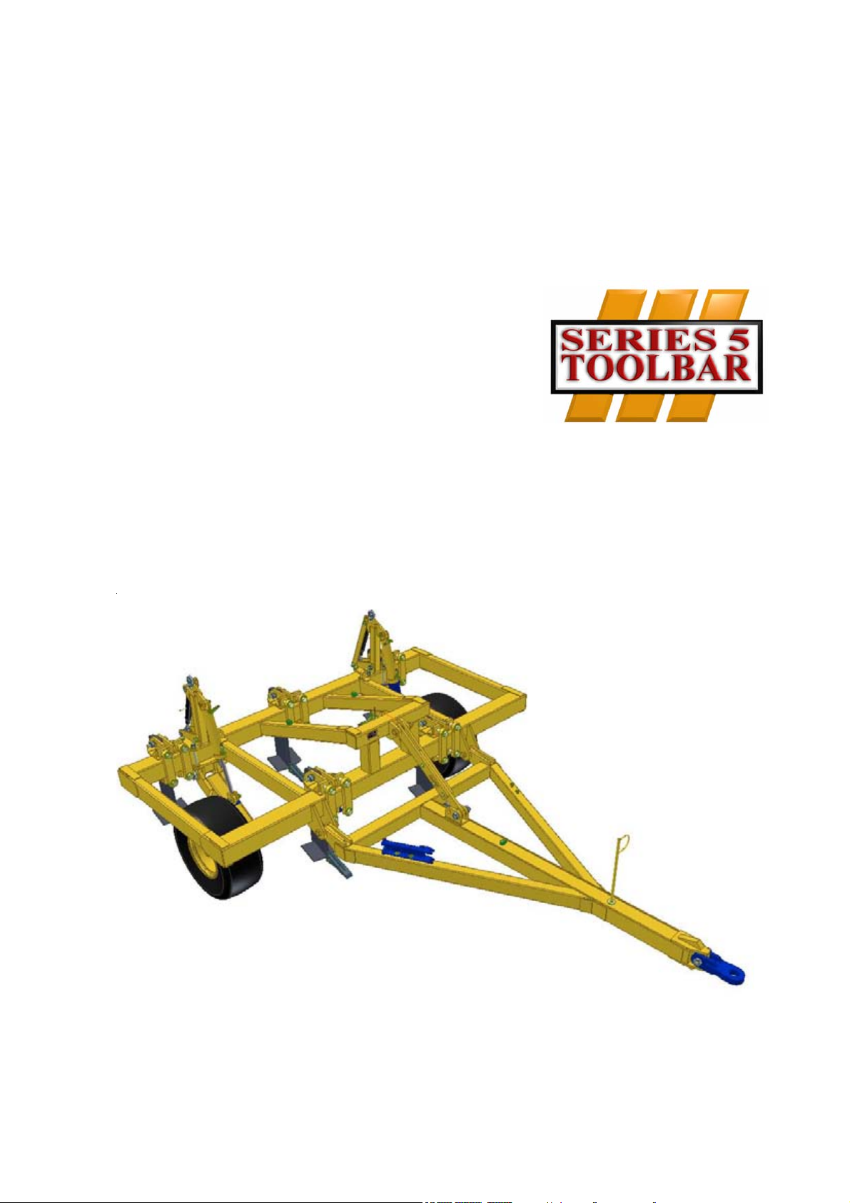
Series 5 Toolbar
2
Operating Instructions
Page 3

Declaration of Conformity
DECLARATION OF CONFORMITY
Simba International Limited hereby declare that the Product described in this Operators Manual, and defined
by the 5 digit Registration number stamped onto the inside of the roller, conforms with the following Directives
and Regulations, and has been certified accordingly.
EC Machinery Directive 89/392/EEC, as amended by 91/3688/EEC, 93/44/EEC, and
93/688/EEC.
In order to fulfill the requirements of health and safety described in the EC Directive, the following standards
and technical specifications have been taken into account:
EN 292 - 1
EN 292 - 2
THE MANUFACTURER
Simba International Limited
Woodbridge Road
SLEAFORD
NG34 7EW
Lincolnshire
NG34 7EW
England.
Telephone 01529 304654.
CERTIFIED ON BEHALF OF SIMBA INTERNATIONAL LIMITED.
Philip J. Wright. BSc (Hons) C Eng. MI Agr.E
Technical Director.
Operating Instructions
3Series 5 Toolbar
Page 4

y
.
a
e
r
r
t
y
e
o
e
e
l
e
s
e
s
s
e
l
Warranty
WARRANTY
TERMS AND CONDITIONS
In this warranty Simba International Ltd., is referred to as “the Company”.
1. Subject to the provisions of this warranty the Company warrants each new machine sold b
it to be sold free from any defect in material or workmanship for a period of 12 months from
date of installation with the end-user.
Some specific items have additional warranty over and above the standard 12 months
Details of these can be obtained upon request directly from the distributor or Simb
International Ltd.
2. If the machine or part thereof supplied by the Company is not in accordance with th
warranty given in clause 1 the Company will at its option:
(a) make good the machine or part thereof at the Company’s expense, or
(b) make an allowance to the purchaser against the purchase price of the machine o
part thereof, or
(c) accept the return of the machine and at the buyers option either:
I) repay or allow the buyer the invoice price of the machine or part thereof, o
II) replace the machine or part thereof as is reasonably practical.
3. This warranty shall not oblige the Company to make any payment in respect of loss of profi
or other consequential loss or contingent liability of the Purchaser alleged to arise from an
defect in the machine or impose any liability on the Company other than that contained in
clause 2.
4. Any claim under this warranty must be notified to the Company in writing specifying th
matters complained of within 14 days from the date of repair.
5. Any claim under this warranty must be made by the original purchaser of the machine and
is not assignable to any third party.
6. If the purchaser hires out the machine to any third party the warranty shall apply only t
matters notified to the Company in writing within 90 days of the date of delivery and claus
1 shall be read as if the period of 90 days were substituted for the period of 12 months.
7. The warranty will cease to apply if:
(a) any parts not made, supplied or approved in writing by the Company are fitted to th
machine or
(b) any repair is carried out to the machine other than by or with the express written approva
of the Company or
(c) any alterations not expressly authorized by the Company in writing are made to th
machine or
(d) the machine is damaged by accident or
(e) the machine is abused or overloaded or used for a purpose or load beyond its design
capabilities, or used in conjunction with a tractor whose power output capability exceed
the stated implement power requirement by more than 40%. For the purpose of thes
terms and conditions, “stated implement power requirement” refers to wheeled tractor
unless specifically stated. These power requirements should be reduced by 20% when
used in conjunction with tracked tractors.
(f) the machine is operated as part of a ‘cultivation train’ where more than one implement i
being towed, without the express written approval of Simba International Ltd.
(g) any maintenance is not carried out in accordance with the service schedules in th
operator’s manual.
(h) the Installation and Warranty Registration Certificate is not received by Simba Internationa
Ltd., Service Dept., Woodbridge Road, Sleaford, Lincolnshire, England, NG34 7EW, within
7 days of installing a new machine.
Series 5 Toolbar
4
Operating Instructions
Page 5

Machine Identification
Enter the relevant data in the following list upon
acceptance of the machine:
Serial Number
Type of Machine
Machine Width
Year of Construction
Delivery Date
First Operation
Accessories
Operating Instructions/Spare Parts List: September 2006
Machine Identification
Dealer Address: Name: ......................................................................
Street: ......................................................................
Place: ......................................................................
Tel.: ................................................................. ....
Dealer's Customer No.: ............................................................
SIMBA Address: SIMBA
Woodbridge Road Ind. Est.
Sleaford
Lincolnshire
NG34 7EW
Tel.: 01529 304654
Fax: 01529 413468
E-Mail: simba.international@simba.co.uk
SIMBA Customer No.: .................................................................
Operating Instructions
5Series 5 Toolbar
Page 6

Series 5 Toolbar
6
Operating Instructions
Page 7

Table of Contents
Contents
Machine Identification .......................................................................................................5
Introduction ............................................................................................. 8
Foreword ......................................................................................................................... 8
Warranty Guidelines ......................................................................................................... 8
1. Safety Data .......................................................................................... 9
1.2 Use for the Intended Purpose ................................................................................. 9
1.3 Operational Safety ............................................................................................... 10
1.4 No Liability for Consequential Damage ................................................................ 10
1.5 Changing Equipment ........................................................................................... 10
1.6 During Operation ................................................................................................. 10
1.7 Servicing & Maintenance ..................................................................................... 10
2. Transportation and Installation ................................................... 11
2.1 Delivery ................................................................................................................ 11
2.2 Transportation ...................................................................................................... 11
2.3 Installation ............................................................................................................ 11
2.4 Hitching-up the machine ....................................................................................... 11
2.5 When driving on the road...................................................................................... 12
2.6 Parking the machine ............................................................................................ 12
3. Adjustment/Operation ................................................................... 13
3.1 Description .......................................................................................................... 13
3.1.1 Mainframe ........................................................................................................... 13
3.1.2 Trailing Kit............................................................................................................ 14
3.1.3 Tines .................................................................................................................... 15
3.2 Work Instructions .................................................................................................. 15
3.3 Checks ................................................................................................................ 15
3.4 Parking ................................................................................................................ 15
3.5 Settings ............................................................................................................... 16
4. Servicing and Maintenance ......................................................... 17
4.1 Servicing ............................................................................................................. 17
4.2 Cleaning .............................................................................................................. 17
4.3 Storage / Parking ................................................................................................. 17
4.4 Operator Support ................................................................................................. 17
4.5 Maintenance Intervals ........................................................................................... 17
4.6 Maintenance Overview ......................................................................................... 18
4.7 Overview of Lubricating Points ............................................................................. 19
4.8 Lubricating the Machine ....................................................................................... 19
4.8.1 Handling of Lubricants.......................................................................................... 19
4.8.2 Hygiene ............................................................................................................... 19
4.8.3 Storage and Handling .......................................................................................... 20
4.8.4 Measures in case of injury through oil ................................................................... 20
4.8.5 Oil Spills............................................................................................................... 20
4.8.6 Oil Fires ............................................................................................................... 20
4.8.7 Waste Oil Disposal .............................................................................................. 20
4.9 Lubricants & Hydraulic Oil .................................................................................... 20
4.9.1 Hydraulic System ................................................................................................. 20
4.9.2 Lubricants ............................................................................................................ 20
5. Parts & Assembly ......................................................................... 21
Operating Instructions
7Series 5 Toolbar
Page 8

Introduction
Introduction
Foreword
Make sure you have read and follow the
Operating Instructions carefully before using
the machine. By doing so, you will avoid
accidents, reduce repair costs and downtime
and increase the reliability and service life
of your machine. Pay attention to the safety
instructions!
SIMBA will not accept any responsibility for
any damage or malfunctions resulting from
failure to comply with the Operating
Instructions.
These Operating Instructions will assist you
in getting to know your component and in using
it correctly for its intended purposes. First, you
are given general instructions in handling the
component. This is followed by sections on
servicing, maintenance and the action to be
taken should a malfunction occur.
We reserve the right to alter
illustrations as well as technical data
and weights contained in these
Operating Instructions for the purpose
of improving the component.
Warranty Guidelines
1. The period of liability for material defects
(warranty) relating to our products is 12
months. In the case of written deviations
from the statutory provisions, these
agreements shall apply.
They shall become effective upon installation
of the machine with the end customer. All wear
parts are excluded from the warranty.
2. Warranty claims must be submitted to the
SIMBA Customer Service Department in
Sleaford via your dealer. It is only possible
to process claims which have been correctly
completed and submitted no later than 14
days after the date of repair.
These operating instructions are to be read
and followed by all persons working on or
with the component, e.g.:
• Operation (including preparation, remedying
of faults in the operating sequence and
servicing).
• Maintenance (maintenance and inspection)
• Transportation.
Together with the Operating Instructions, you
receive a Spare Parts List and a Machine
Registration form. Field service technicians
will instruct you in the operation and
servicing of your machine. Following this,
the Machine Registration form is to be
returned to SIMBA. This confirms your
formal acceptance of the machine. The
warranty period begins on the date of delivery.
3. In the case of deliveries made under the
warranty which are subject to the return of
the old parts, the old parts must be returned
to SIMBA within 28 days after the damage
occurred.
4. In the case of deliveries made under the
warranty which are not subject to the return
of the old parts, these parts must be kept for
the purpose of further decisions for a period
of 3 months after receipt of the warranty claim.
5. Warranty repairs to be carried out by
outside companies, or repairs which are
expected to take more than 10 working
hours, must be agreed upon in advance with
the Customer Service Department.
Series 5 Toolbar
8
Operating Instructions
Page 9
Safety Data
1. Safety Data
The following warnings and safety instructions
apply to all sections of these Operating
Instructions. All safety instructions for the
machine should be followed.
1.1 Operating Instructions:
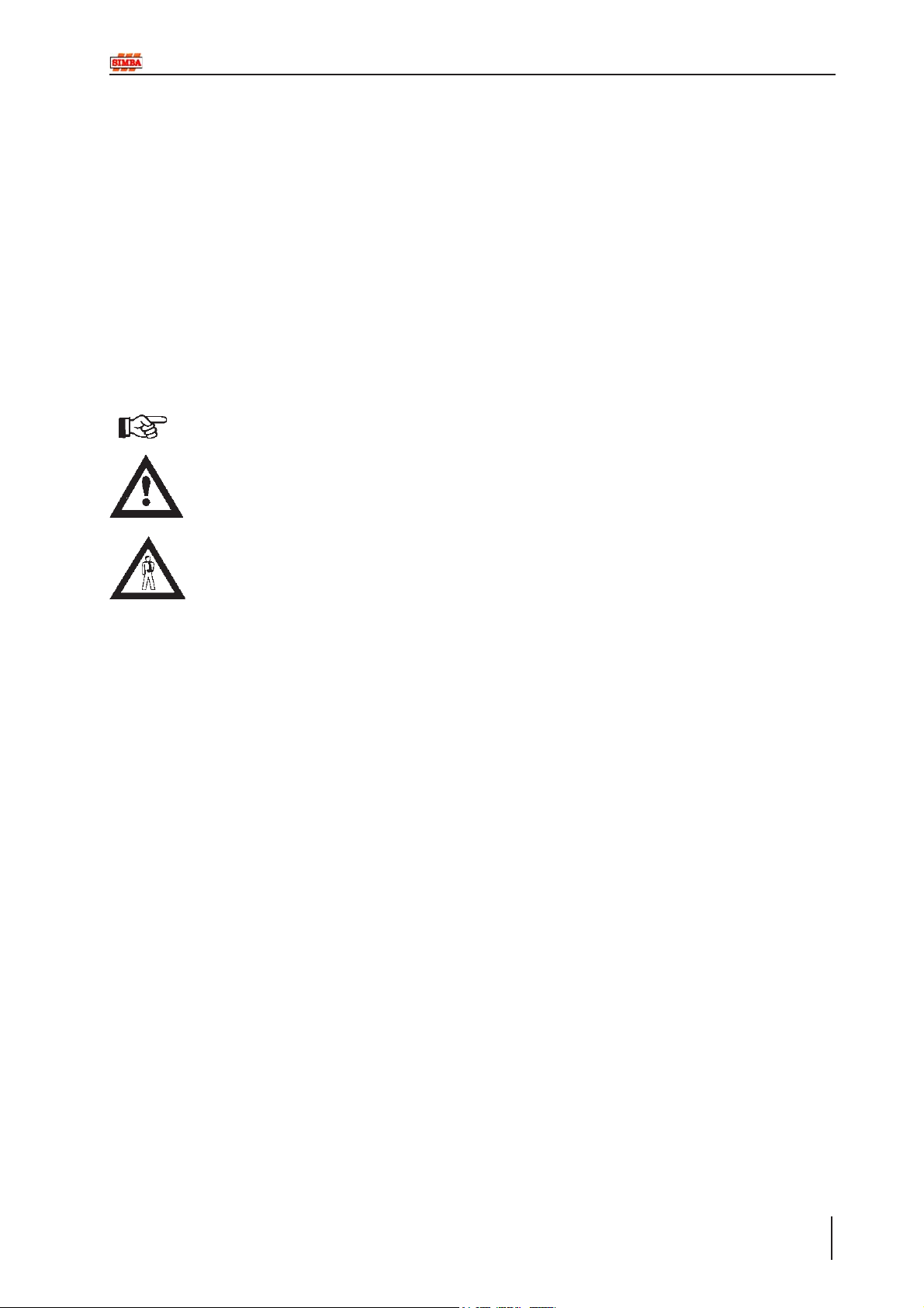
The Operating Instructions distinguish
between three different types of warning and
safety instructions. The following graphic
symbols are used:
Important!
Risk of injury!
Risk of fatal and serious injuries!
It is important that all the safety instructions
contained in these Operating Instructions
and all the warning signs on the machine
are read carefully.
1.2 Use for the Intended
Purpose
The SIMBA Series 5 Toolbar is built using
the latest technology and in accordance with
the relevant recognised safety regulations.
However, risks of injury for the operator or third
parties and impairment of the machine or
other tangible assets can arise during use.
The Toolbar unit is only to be operated when
in a technically perfect condition and for the
intended purpose, taking into consideration
safety and risks and following the Operating
Instructions. In particular, faults that can
impair safety are to be remedied
immediately.
Original parts and accessories from SIMBA
have been specially designed for this unit.
Spare parts and accessories not supplied by
us have not been tested or authorised.
Installation or use of non-original SIMBA
products may have a detrimental effect on
specific design features of the unit and affect
the safety of machine operators. SIMBA will
accept no liability for damage resulting from
the use of non-original parts or accessories.
Ensure that the warning signs are legible.
Replace any signs that are missing or
damaged.
These instructions must be followed in order
to prevent accidents. Inform other users of
the warnings and safety instructions.
Do not carry out any operations which may
affect safe use of the machine.
The SIMBA Series 5 Toolbar is designed
solely as a Toolbar unit. Use for any other
purpose, e.g., as a means of transport, will
be deemed to be improper use. SIMBA will
accept no liability for damage resulting from
improper use. The risk will be borne solely by
the operator.
Operating Instructions
9Series 5 Toolbar
Page 10

Safety Data
1.3 Operational Safety
All protective and safety equipment, such as
removable protective equipment, must be in
place and functioning reliably before the
machine is put in use.
Check screws and bolts regularly for
tightness and retighten if necessary.
In the event of malfunctions, stop and
secure the machine immediately.
Ensure that any faults are remedied
immediately.
1.4 No Liability for
Consequential Damage
The Series 5 Toolbar has been manufactured
by SIMBA with great care. However,
problems may still occur when it is used for
the intended purpose. This may include:
1.5 Changing Equipment
• Use suitable supports to secure any raised
frame sections suspended above you!
• Caution! Risk of injury due to projecting parts!
1.6 During Operation
The person in charge must:
• provide the operator with a copy of the
Operating Instructions.
• ensure that the operator has read and
understood the instructions.
1.7 Servicing &
Maintenance
Ensure that regular checks and inspections
are always carried out within the periods
required by law or specified in these
Operating Instructions.
• Worn wearing parts.
• Damage caused by external factors.
• Incorrect driving speeds.
• Incorrect setting of the unit (incorrect
attachment, non-adherence to the Setting
instructions).
Therefore, it is crucial to always
check your Toolbar unit before and
during operation for correct
operation and adequate application
accuracy.
Compensation claims for damage which has
not occurred to the component is excluded.
This includes any consequential damage
resulting from incorrect operation.
Prior to performing maintenance and
servicing work, ensure that the machine is
positioned on solid, level ground and is secure
and stable.
Before cleaning the unit with water, steam jets
(high-pressure cleaning apparatus) or other
cleaning agents, cover all openings into
which, for reasons of safety or operation, no
water, steam or cleaning agents are to
penetrate.
When carrying out servicing and maintenance
work, retighten any loose screw connections.
Series 5 Toolbar
10
Operating Instructions
Page 11

Transportation & Installation
2. Transportation and
Installation
Transportation and initial installation of the
machine are described in this chapter.
2.1 Delivery
The Toolbar unit is normally delivered, fully
assembled, on a (low-bed) truck.
The machine can be lifted off with a crane,
fork-lift truck, or other suitable lifting
equipment.
When doing so, the weight, the centre of
gravity and the attachment points on the unit
are to be taken into account.
Depending on the lifting gear, attachment is
only to be at appropriate points on the frame.
2.3 Installation
When carrying out installation and
maintenance work there is a higher risk of
injury. It is important that you familiarise
yourself with the component and read the
Operating Instructions beforehand.
2.4 Hitching-up the
machine
When hitching-up the machine,
ensure that no-one is between the
tractor and the machine.
• Couple the machine to the tractor.
• Hook up the hydraulics.
Connect the hydraulic system only
when the hydraulic couplings are
depressurised.
2.2 Transportation
The Series 5 Toolbar can be transported on
public roads by hitching it up to a tractor or on
a low-bed truck.
The Series 5 Toolbar unit must be lifted clear
of the ground for road transport when
transported behind a tractor.
• It is important to observe the permitted
dimensions and weights when transporting the
machine.
• Use suitable lifting gear, e.g. a fork-lift truck.
• If the machine is transported on a trailer or a
flat-bed truck, it must be secured using straps
or other devices.
• Before transporting the machine on public
roads, it must be adjusted to its transportation
position and the stipulations relating to road
transportation fulfilled.
• The maximum permissible speed is 25 km /h.
11Series 5 Toolbar
Operating Instructions
Page 12

Transportation & Installation
2.5 When driving on the
road
When driving on the road the machine must
be converted to the transportation position.
There is a risk of injury on specially
sharpened edges and when
making adjustments on the
machine.
When driving on the road, raise the
machine completely to prevent the
working elements dragging on the
ground. Ensure the transport locks
are fitted to the hydrailic cylinders
in road transport.
The maximum permissible road transport speed
is 25 km /h.
2.6 Parking the machine
In order to avoid damage as a result of
moisture, the machine should be parked, if
possible, indoors or under cover.
When manoeuvring the machine,
pay attention to your surroundings.
Ensure that nobody is in the
manoeuvring area (watch for
children!).
• Park the machine on level and solid ground.
• Lower the machine so that it is supported.
• Disconnect hydraulic lines from the tractor.
• Unhitch the machine.
Series 5 Toolbar
12
Operating Instructions
Page 13

3. Adjustment/Operation
2
Adjustment / Operation
Fig. 3.01: Series 5 Toolbar Frame
3.1 Description
3.1.1 Mainframe
1. Attachment points for trailing unit
2. Mainframe
The SIMBA Series 5 Toolbar is designed for
deep soil loosening. This promotes good root
development by providing a non-compacted
soil profile.
1
Operating Instructions
13Series 5 Toolbar
Page 14

Adjustment / Operation
4
6
7
5
3
Fig. 3.02: Series 5 Toolbar Trailing Kit
3.1.2 Trailing Kit
1. Hitch
2. Drawbar
3. Transport Wheels
4. Toplinks (wheel adjustment)
5. Drawbar Adjuster (pitch adjustment)
6. Transport Locks
7. Hydraulic Cylinders
The wheel units are used both for depth control
and for road transport. When in road transport
the machine is lifted clear of the ground using
a hydraulic cylinder on each wheel unit.
6
2
1
For depth control in work, each wheel is set
via toplink adjusters to the required working
depth. When in work the hydraulic cylinder on
each wheel is used in the fully closed position.
Series 5 Toolbar
14
Operating Instructions
Page 15

Adjustment / Operation
3.1.3 Tines
3.2 Work Instructions
Turning:
Before turning, the machine should
be eased out of work while driving.
Likewise, it should eased back into
work once the turn has been
completed.
In work the Series 5 Toolbar can be driven at
speeds between 8-12km/h.
3.3 Checks
The working quality depends on the
adjustments and checks made prior to and
during work, as well as on regular servicing
and maintenance of the component.
Before beginning work it is therefore
important to carry out any necessary servicing
required.
Fig. 3.03: Series 5 Toolbar Tines
The subsoiler times are manufactured from
40mm thick high tensile steel to reduce
bending in adverse conditions. The tine units
are also shear bolt protected to minimise the
risk of damage to the legs and frame. The
tines feature 2 part pinned-on tips and
replacable wings.
Working Elements
• Are the working elements in good working
order?
3.4 Parking
In order to avoid damage as a result of
moisture, the machine should be parked, if
possible, indoors or under cover.
When manoeuvring the machine,
pay attention to your surroundings.
Ensure that nobody is in the
manoeuvring area (watch for
children!).
• Park the machine on level and solid ground.
• Lower the machine so that it is supported.
• Disconnect hydraulic lines from the tractor.
• Unhitch the machine.
Operating Instructions
15Series 5 Toolbar
Page 16

Adjustment / Operation
A
B
Fig. 3.04: Series 5 Toolbar Settings
3.5 Settings
The drawbar may be attached to the tractor
rigid drawbar or the pick up hitch. Altering the
length of the drawbar adjuster (C) will raise
or lower the back of the frame to alter the
draught requirements and quality of work. The
drawbar adjuster may also be used to take
account of varying tractor drawbar heights.
Alteration of working depth is effected by
altering the length of the top link on each wheel
unit (A). Both wheel units must be set to exactly
the same length. Remember to check the
wheels for clearance after any adjustment.
The tie bars should NEVER be removed,
therefore should reduced depth still be
required when working at the limit of the tie
bars; the tines will need to be raised in their
clamps.
C
To adjust working depth proceed as follows: -
Raise the machine and drive forward onto
hard ground. Lower the machine fully to
eliminate pressure in the hydraulic system.
Retain the hydraulic lever in the ‘lower’ or ‘float’
position, then lengthen the adjusters to
decrease depth or shorten to increase depth
as required.
When entering work ensure that the transport
locking units are removed, then lower the
tines to the ground, draw forwards until the
correct operating depth is achieved. In work
the hydraulic cylinders (B) should be in the fully
closed position. To leave work, extend the
hydraulic cylinders so that the tines are clear
of the ground.
Series 5 Toolbar
16
Operating Instructions
Page 17

Servicing and Maintenance
4. Servicing and
Maintenance
Follow the safety instructions for
servicing and maintenance.
4.1 Servicing
Your Series 5 Toolbar unit has been designed
and constructed for maximum performance,
operational efficiency and operator
friendliness under a wide variety of operating
conditions.
Prior to delivery, your Toolbar unit has been
checked at the factory and by your authorised
dealer to ensure that you receive it in optimum
condition.
To ensure trouble-free operation, it is
important that servicing and maintenance
work is performed at the recommended
intervals.
When changing points on tines
extreme care should be taken.
Wear goggles at all times when
changing tine points.
4.2 Cleaning
In order to ensure that the Toolbar is always
in operating condition and to achieve
optimum performance, perform the cleaning
and servicing work at regular intervals.
4.3 Storage / Parking
In order to avoid damage as a result of
moisture, the machine should be parked, if
possible, indoors or under cover.
4.4 Operator Support
If you have a problem, please contact Your
dealer. They will endeavour to solve any
problems which may occur and provide you
with support at all times.
In order to enable your dealer to deal with
problems as quickly as possible, it helps if
you can provide them with the following data.
Always state the:
• Customer Number
• Name and Address
• Machine Model
• Serial Number
• Date of Purchase and Operating Hours
• Type of Problem
4.5 Maintenance Intervals
Apart from daily maintenance, the
maintenance intervals are based on the
number of operating hours and time data.
Keep a record of your operating
hours to ensure that the specified
maintenance intervals are adhered
to as closely as possible.
Never use a Series 5 Toolbar unit
that is due for maintenance. Ensure
that all deficiencies found during
regular checks are remedied
immediately.
Place the machine on suitable
supports when working
underneath! Do not work under a
machine which is not supported!
On a new machine tighten all nuts and bolts
after 5 hours work and again after 15 hours.
This also applies to parts that have been
moved or replaced. After the initial 15 hours
of work a once a week check should be
sufficient depending on daily work rates.
Operating Instructions
17Series 5 Toolbar
Page 18

Servicing and Maintenance
4.6 Maintenance Overview
--- ---
Series 5 Toolbar Maintenance Overview
Series 5 Toolbar
18
Operating Instructions
Max. Bolt Torques
M12 8.8 10 KgM ( 73 lb.ft)
M16 8.8 24 KgM ( 176 lb.ft)
M20 8.8 47 KgM ( 345 lb.ft)
M24 8.8 80 KgM ( 587 lb.ft)
M30 8.8 150 KgM (1100 lb.ft)
M36 8.8 280 KgM (2055 lb.ft)
Check they are firm ly seated. Tighten / Sec ure if necessary -
Refer to table below for bolt torques
After first operation Instructions Interval Note
Check all screw, bolt and plug connections
During operation
Lubricate m achine See overview of lubricating points --- Page 19
Toplinks / Drawbar adjuster Check setting and ensure they are firmly secured daily Page 16
Check wheel studs for tightness Check on delivery and before transporting the machine --- ---
Lubricate m ac hine See overview of lubricating points --- Page 19
Hydraulic system and components Check seals, signs of crushing/wear, function and c ondition daily ---
After season
Tines, points and wings . Check condition, mountings and settings daily Page 15
Safety devices (transport locks) Check condition and function daily ---
Lubricate m achine See overview of lubricating points --- Page 19
After 4 years
Toplinks / Bolts Grease any exposed threads --- ---
Entire machine Carry out cleaning and maintenance --- ---
Hydraulic pipes Replace MRL Anh I EN 1533
5/8" UNC 24 KgM ( 175 lb.ft)
Page 19

Servicing and Maintenance
4.7 Overview of Lubricating Points
Series 5 Toolbar lubrication points Interval Diag. No.
Trailing Unit Wheel Pivot and Pivot Bolt 50 Hours 4.01
Trailing Unit Wheel Bearings 50 Hours 4.02
Á
Fig. 4.01: Wheel Pivot Grease Points
4.8 Lubricating the
Machine
Please read the section entitled "Using
Lubricants" carefully before lubricating the
machine.
The machine must be lubricated regularly in
order for it to remain serviceable. Regular
lubrication also contributes towards extending
the service life of your machine.
The recommended lubricating intervals are
specified in "Inspection" and "Maintenance
Intervals".
After it has been washed using a highpressure hose or steam cleaned, the machine
should always be lubricated using a grease
gun. Ensure that the universal joints and
splined shafts are lubricated regularly.
4.8.1 Handling of
Lubricants
Please ensure that you read the following
instructions as well as the relevant
information. This also applies to any of your
employees who handle lubricants.
Fig. 4.02: Wheel Hub Grease Points
4.8.2 Hygiene
Lubricants do not present a health hazard
provided they are used for their specified
purpose.
In the case of prolonged skin contact,
lubricants - especially low-viscosity oils - may
remove the natural layer of fat contained in
the skin, resulting in dryness and possible
irritation .
It is important to take extreme care when
handling waste oil as it may contain other
irritants.
Vapours given off by cleaning agents and oils
are also a potential health hazard.
You should therefore not carry any oily cloths
around. Change soiled work clothing as soon
as possible.
Always exercise extreme care and observe
the recommended hygiene rules when
handling mineral oil products. Details of these
handling regulations can be found in
information provided by the health authorities.
Operating Instructions
19Series 5 Toolbar
Page 20

Servicing and Maintenance
4.8.3 Storage and
Handling
• Always store lubricants where they cannot be
accessed by children.
• Never store lubricants in open or unlabelled
containers.
Fresh Oil:
• Apart from taking the usual care and obser-
ving hygiene rules, there is no need to take
any special precautions when handling
fresh oil.
Waste Oil:
• Waste oil can contain harmful contaminants
which may cause skin cancer, allergies and
other illnesses.
Attention!
Oil is a toxic substance. Should you swallow
any oil, do not try to vomit. Contact a doctor
immediately.
Protect your hands with barrier cream or wear
gloves to avoid contact with the skin. Wash
off any traces of oil thoroughly with soap and
hot water.
• Wash your skin thoroughly with soap and water.
• Use special cleaning agents to clean any
dirt off your hands.
• Never wash oil residue from your skin with
petrol, diesel fuel or paraffin.
• Avoid skin contact with any oily clothing.
• Do not keep any oily rags in your pockets.
• Wash soiled clothing before wearing it
again.
• Ensure that any oily footwear is disposed of in
the proper manner.
4.8.4 Measures in case of
If oil is swallowed:
If oil is swallowed, it is important not to induce
vomiting. Contact a doctor immediately.
Skin irritation caused by oil:
In case of prolonged skin contact, wash off
the oil with soap and water.
4.8.5 Oil Spills
Use either sand or a suitable granular
absorbent to soak up any spilt oil. Dispose of
the oil-contaminated absorbent in the proper
manner.
4.8.6 Oil Fires
Never use water to extinguish an oil fire. The
oil will float on the water causing the fire to
spread.
Burning oil-lubricant must be extinguished
using a carbon dioxide powder or foam
extinguisher. Always wear respiratory
equipment when dealing with fires of this type.
4.8.7 Waste Oil Disposal
Oil-contaminated waste and used oil must be
disposed of in accordance with current
legislation.
Waste oil must be collected and disposed of
in accordance with local regulations. Never
pour used oil into unsealed sewage systems
or drains or onto the ground.
4.9 Lubricants &
Hydraulic Oil
4.9.1 Hydraulic System
The hydraulic fluid from the tractor is mixed
with the hydraulic fluid from the machine.
injury through oil
Eyes:
Should any oil be splashed into your eyes,
rinse with water for 15 minutes. If the eye is
still irritated, contact a doctor immediately
Series 5 Toolbar
20
Operating Instructions
The supplied machine hydraulic system
contains Total AZOLLA ZS 32 oil.
4.9.2 Lubricants
The lubricating points on the machine can be
lubricated with multigrade lubricating grease
as specified in DIN 51825 KP/2K - 40.
Page 21

5. Parts & Assembly
Table of contents
Series 5 Toolbar Complete................... 22
Trailing Kit Assembly ............................ 24
Mainframe ............................................ 26
Tine Assembly ...................................... 28
Hydraulic Components ......................... 62
Hydraulic Circuit ................................... 64
Parts & Assembly
Operating Instructions
21Series 5 Toolbar
Page 22

Parts & Assembly
AAS2374
PJW
06/12/2005
Series 5 Toolbar
22
Operating Instructions
TOOLBAR S5 4m 5 TINE FULL ASSEMBLY
Page 23

Parts & Assembly
AS2374
ITEM PART NO DESCRIPTION QTY COMMENTS
1
2
3
4
5
6
7
8
9
10
11
12
13
14
15
16
17
18
19
20
21
22
23
24
25
26
27
28
29
30
31
32
33
34
35
36
37
38
39
40
41
42
43
44
45
46
47
48
49
50
AS2373 TOOLBAR - S4/5 TINE AND CLAMP ASSEMBLY 5
AS2375 TRAILING KIT ASSEMBLY 1
AS2383 TOOLBAR S4/5 MAIN FRAME ASSEMBLY 1
TOOLBAR S5 4m 5 TINE ASSEMBLY
Operating Instructions
23Series 5 Toolbar
Page 24

Parts & Assembly
AAS2375
ARH
12/04/2004
FLATLINER
TRAILING KIT ASSEMBLY
Series 5 Toolbar
24
Operating Instructions
Page 25

Parts & Assembly
AS2375
ITEM PART NO DESCRIPTION QTY COMMENTS
1
2
3
4
5
6
7
8
9
10
11
12
13
14
15
16
17
18
19
20
21
22
23
24
25
26
27
28
29
30
31
32
33
34
35
36
37
38
39
40
41
42
43
44
45
46
47
48
49
50
P00305 HOSE MAST - 150RHS 1
P00871 ADJUSTER POST 2
P03503 WHEEL LEG RH 1
P00641 6 STUD HUB ASSEMBLY 2
P00159 TOPLINK CAT 3 19" 2
P01274 PIN Ø25x115 3
P02484 LYNCH PIN CAT 2 8
P02890 BUSH SPRUNG - Ø72xØ62x60 4
P01645 BUSH SPRUNG - Ø32xØ26x32 4
P03502 WHEEL LEG LH 1
P02608 WASHER FLAT M30 24
P02011 NUT LOCK M30 10
P02604 WASHER FLAT M24 Ø50 13
P02593 WASHER SPRING M24 1
P00717 NUT PLAIN M24 1
P10857 PIN Ø31.75x180 2
P04010 WASHER FLAT M60x10 2
P00036 BOLT M30x180 GR. 8.8 2
P00538 PIN Ø31.75x150 2
P14813 TIE BAR - 696mm CTRS 2
P01148 TRANSPORT PIN Ø25x127 2
P01149 BUSH Ø30xØ24x23 2
P03495 DRAWBAR S5 TRAILING KIT 1
P02480 SHACKLE TYPE I 1 Ø46, Ø68x9 SLOT
P04342 CAMBER PLAT E 3mm 2
P01564 TRANSPORT LOCK 100x400 2
P02483 LYNCH PIN CAT 1 4
P01697 NUT PLAIN M60 HALF 4 HALF NU T
P09112 CLAMP ½" BSP PAIR 3
P09113 CLAMP - TOP PLATE 3
P10278 BOLT M8x45 GR. 8.8 3
P00801 LOWER AXLE PIVOT 2
P00802 UPPER AXLE PIVOT 2
P06672 BOLT M30x300 GR. 10.9 8 35mm T HREAD
P03958 WHEEL ASSY 18X19.5 6 STUD 2
AS2392 T OPLINK - SIMBA FAB 1 P01562
P01871 BOLT M60x330 2
P13344 1/2 NUT PLAIN M45x3 4
P14220 BOLT M45x175 2 SUPERCEDES P00383
P12891 NIPPLE - GREASE M10 2
AS2393 HYDRAULIC COMPONENT LAYOUT 1
TRAILING KIT ASSEMBLY
Operating Instructions
25Series 5 Toolbar
Page 26

Parts & Assembly
AAS2383
PJW
09/12/2005
Series 5 Toolbar
26
Operating Instructions
TOOLBAR S4/5 MAIN FRAME ASSEMBLY
Page 27

Parts & Assembly
AS2383
ITEM PART NO DESCRIPTION QTY COMMENTS
1
2
3
4
5
6
7
8
9
10
11
12
13
14
15
16
17
18
19
20
21
22
23
24
25
26
27
28
29
30
31
32
33
34
35
36
37
38
39
40
41
42
43
44
45
46
47
48
49
50
P03494 T OOLBAR S5 4m 1
P13344 1/2 NUT PLAIN M45x3 6
P14221 BOLT M45x220 3 SUPERCEDES P00051
P05122 SERIAL PLATE 1
P13092 RIVET Ø3x10x Ø6 HEAD 4
P13013 MANUAL CASE Ø100 1
P14222 MK4 TOOLBAR - OPERAT ORS MANUAL 1
T OOLBAR S4/5 MAIN FR AME ASSEM BLY
Operating Instructions
27Series 5 Toolbar
Page 28

Parts & Assembly
PJW
A
AS2373
05/12/2005
Series 5 Toolbar
28
Operating Instructions
TOOLBAR - S4/5 TINE AND CLAMP ASSEMBLY
Page 29

Parts & Assembly
AS2373
ITEM PART NO DESCRIPTION QTY COMMENTS
1
2
3
4
5
6
7
8
9
10
11
12
13
14
15
16
17
18
19
20
21
22
23
24
25
26
27
28
29
30
31
32
33
34
35
36
37
38
39
40
41
42
43
44
45
46
47
48
49
50
P05737 TINE ST RAIGHT 40mm 1 200AR200D
P02016 POINT BODY - S4/5 1
P02017 TIP - S4 CAST 1
P02481 ROLL PIN Ø16x40 1
P00006 BOLT M12x80 GR. 8.8 1
P02601 WASHER FLAT M12 2
P02007 NUT LOCK M12 1
P14241 WING RH S4 150mm 1
P14240 WING LH S4 150mm 1
P00017 BOLT M24x100 GR. 8.8 2
P02010 NUT LOCK M24 2
P14239 TINE CLAMP RH S5 1
P14238 TINE CLAMP LH S5 1
P02012 NUT LOCK M36 5
P00036 BOLT M30x180 GR. 8.8 1
P02011 NUT LOCK M30 1
P02772 PLATE - RTG S5 2
P02609 M36 FLAT WASHER 4
P00045 BOLT M36x200 GR. 8.8 5
TOOLBAR - S4/5
TINE AND CLAMP ASSEMBLY
Operating Instructions
29Series 5 Toolbar
Page 30

Parts & Assembly
A
AS2393
PJG
16/12/2005
S5 TOOLBAR
HYDRAULIC COMPONENT LAYOUT
Series 5 Toolbar
30
Operating Instructions
Page 31

Parts & Assembly
AS2393
ITEM PART NO DESCRIPTION QTY COMMENTS
1
2
3
4
5
6
7
8
9
10
11
12
13
14
15
16
17
18
19
20
21
22
23
24
25
26
27
28
29
30
31
32
33
34
35
36
37
38
39
40
41
42
43
44
45
46
47
48
49
50
P05399 BOLT M6x75 GR. 8.8 2
P07981 NU T LOCK M6 2
P05400 WASHER FLAT M6 4
P07952 HA 1/2"x3660 2
P00184 HA 1/2"x3660 2
P02263 DOWTY SEAL ½" BSP 17
P00200 BANJO BLOCK ½" BSP 4
P00201 BANJO BOLT ½" BSP 4
P12010 HA 1/4"x300 90° 2
P02881 ADAPT OR MALE-MALE ¼" BSP 2
P02741 DOWTY SEAL ¼" BSP 2
P00191 HA 1/2"x3660 2
P00205 QUICK RELEASE MALE - ½" BSP 2
P02734 ELBOW MALE-FEM COMPACT ½" BSP 2
P00206 ADAPT OR MALE-FEM ½" BSP 2
P00209 ADAPTOR 4 WAY ½" BSP 1
P02882 ADAPTOR FEM ½" - FEM ¼" BSP 1
P02742 ADAPT OR T ¼" BSP 1
P00872 FDC - 1/2" BSP 1
P02883 PILOT CHECK VALVE 2
P00203 ADAPT OR MALE-MALE ½" BSP 7
P00164 CYLINDER - Ø3¾"x400 - 45 2 673-1073
TOOLBAR SERIES 5 - HYDRAULIC COMPONENTS
Operating Instructions
31Series 5 Toolbar
Page 32

Parts & Assembly
AAS2394
PJG
16/12/2005
S5 TOOLBAR
HYDRAULIC HOSE LAYOUT
Series 5 Toolbar
32
Operating Instructions
Page 33

Parts & Assembly
AS2394
ITEM PART NO DESCRIPTION QTY COMMENT S
1
2
3
4
5
6
7
8
9
10
11
12
13
14
15
16
17
18
19
20
21
22
23
24
25
26
27
28
29
30
31
32
33
34
35
36
37
38
39
40
41
42
43
44
45
46
47
48
49
50
P07952 HA 1/2"x3660 2
P00184 HA 1/2"x3660 2
P12010 HA 1/4"x300 90° 2
P00191 HA 1/2"x3660 2
TOOLBAR SERIES 5 - HYDRAULIC HOSE LAYOUT
Operating Instructions
33Series 5 Toolbar
Page 34

Series 5 Toolbar
34
Operating Instructions
 Loading...