

Page 1
Part Lists Great Plains Manufacturing, Inc. 1
Nutri Pro Wing Pivot Update Manual
®
Fertilizer Applicators
Null4:
Nutri-Pro
General Information
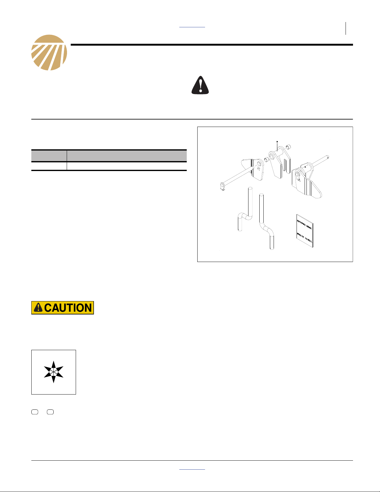
These instructions explain how to install a wing pivot
hinge update kit. It takes one kit (includes a left and a
right hinge) to update one implement:
Kit Kit Description
407-697A NP Wing Pivot Update
Tools Required
• basic hand tools
• two jack stands
• right angle grinder
• welder capable of welding 3/8” material, welding visor
and gloves
• Great Plains green spray paint (p/n 821-001C)
When you see this symbol, the subsequent instructions
and warnings are serious - follow without exception.
Your life and the lives of others depend on it!
Work Location
Move the implement to a location with:
• flat, smooth non-flammable surface free of combustibles
• adequate illumination
• clear surface beneath for recovery of any falling
or dropped parts
Sharp Object Hazard:
Be careful working near discs and tines. Edges may be sharp.
Notations and Conventions
Null4:
U
F
L
D
Call-Outs
11 19
to
Two-digit callouts in the range 11 to 19 reference new parts from the list on page 5.
“Left” and “Right” are facing in the
direction of machine travel. An orienta-
R
tion rose in the line art illustrations
shows the directions of Left, Right,
Front, Back, Up, Down.
B
Figure 1
Nutri-Pro® Hinge Update Kit
32203
© Copyright 2010 Printed 07/13/2011 Part Lists 407-703M
Page 2
2 Great Plains Manufacturing, Inc. Front Page Part Lists Nutri-Pro Hinge Update Kit
Setup
1. Place one jack stand under the end of the wing
frame and one under the rear tube in the middle of
the wing.
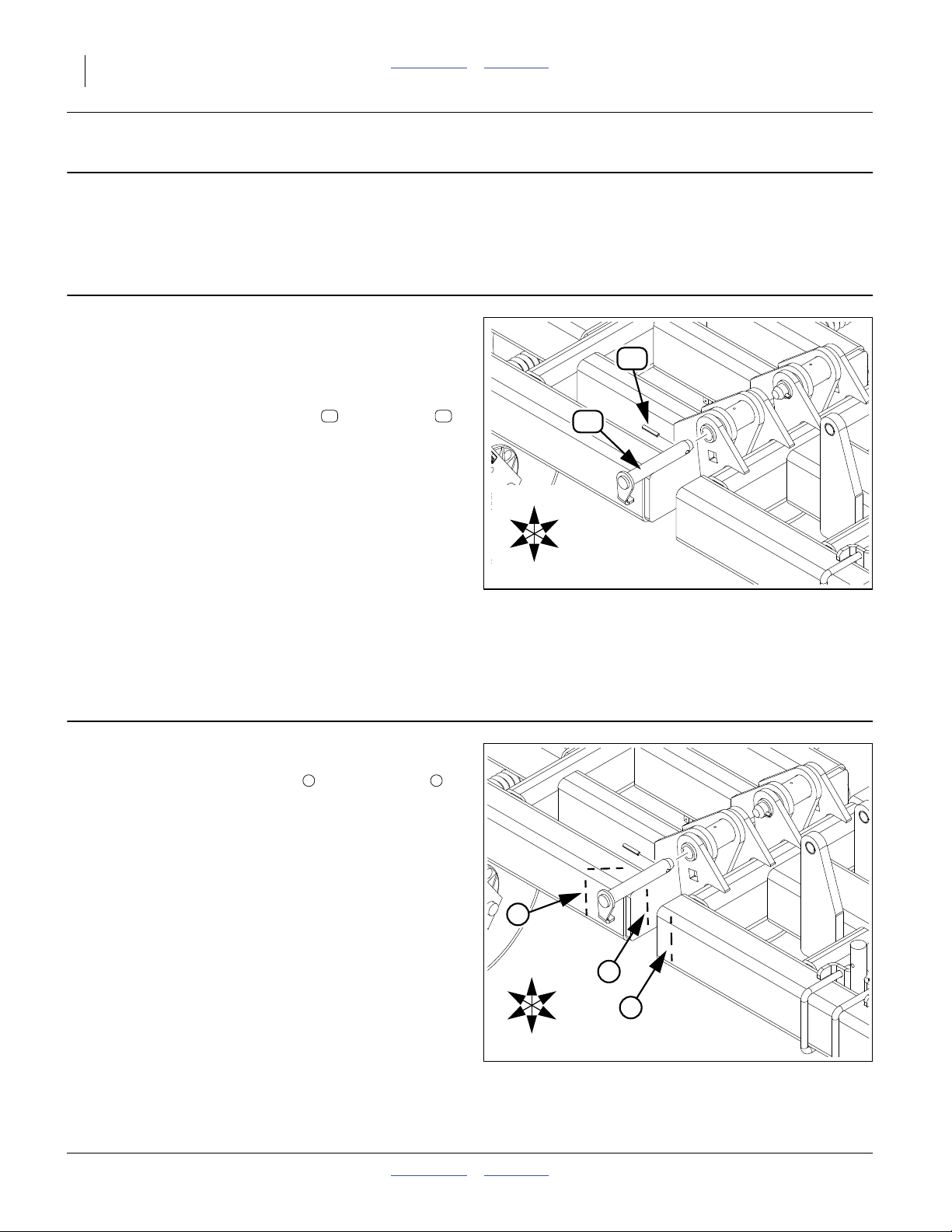
Remove
Refer to Figure 2
Note: These instructions begin with the left wing of the
implement and all illustrations correspond by
showing the left wing. Perform all steps for the
right wing also.
2. Remove only the forward roll pin and pivot pin
that hold the left wing and center frames together.
3. Only on models NP30A-11, NP30A-13, NP30L-11
and NP30L-13:
Remove the coulter assembly from the wing - nearest the pivot. The straight shank will be replaced by
an offset shank in step 14.
53 52
Null4:
R
F
U
D
53
52
B
L
Figure 2
Remove Forward Pivot Pin
32214
Null4:
Grind
Refer to Figure 3
4. Remove the paint before welding by grinding the
ends of both the center frame and wing frame
tubes. (The only areas that need grinding are where
welding will occur.)
1 2
R
F
1
U
1
B
2
L
D
Figure 3
Grind Ends
32214
407-703M Front Page Part Lists 07/13/2011
Page 3

Attach New Pivot Weldments Front Page Part Lists Great Plains Manufacturing, Inc. 3
Attach New Pivot Weldments
Refer to Figure 4 and Figure 5
R
F
19
U
B
L
D
32212
5. Insert one bushing into each end of center LH
wing pivot weldment.
6. On the end of the LH center frame slip the slotted
end of the center LH wing pivot weldment .
407-696H CENTER LH WING PIVOT WLDMNT
13
7. Test fit long pivot pin before welding.
8. For accurate placement locate dimensions from outside edge of middle section end plate and top of middle section front tube then weld in place around all
edges.
Note: Weld should be .38 fillet all sides all around.
9. On the end of the LH wing frame place the left front
wing pivot .
407-695H LEFT FRONT WING PIVOT
12
10. For accurate placement locate dimensions from top
of front wing tube and inside edge of tube on end of
wing then weld all around.
Note: Weld should be .38 fillet all sides all around.
11. To protect against corrosion, paint areas that were
grinded and where new welds are. Use Great Plains
green spray paint.
12
19
13
16
16
53
17
19
13
12
Figure 4
Left Wing Frame
Reassemble
12. Join the wing frame to the center frame by placing
the new long pivot pin through all bracket holes
and secure with roll pin saved from step 2.
407-700H NP WING PIVOT PIN LONG WLDM
16
13. Insert grease zerk into center weldment.
800-001C GREASE ZERK STRAIGHT 1/4-28
17
16
53
17
Figure 5
Dimensions
32216
07/13/2011 Front Page Part Lists 407-703M
Page 4

4 Great Plains Manufacturing, Inc. Front Page Part Lists Nutri-Pro Hinge Update Kit
Replace Coulter
Refer to Figure 6
14. For models where straight shank was removed,
insert left offset shank into front wing pivot, align
coulter with shank and attach coulter.
820-132C 1 1/2 X 22 OFFSET SHANK
18
18
R
18
U
B
Null4:
Finish
15. Repeat all steps for right wing.
F
L
D
Figure 6
Offset Shank
32211
407-703M Front Page Part Lists 07/13/2011
Page 5

Appendix Front Page Part Lists Great Plains Manufacturing, Inc. 5
Appendix
Part Lists
New Parts
The part call-out numbers in this list match all Figures in
these installation instructions. Part descriptions match
those in your updated Parts Manual.
Quantities are units (“ea”).
Kit Contents
407-697A
NP Wing Pivot Update
Callout Quantity Part Number Part Description
11 1 407-703M NUTRIPRO HINGE UPDATE MANUAL
12 1 407-695H LEFT FRONT WING PIVOT
13 1 407-696H CENTER LH WING PIVOT WLDMNT
14 1 407-698H CENTER RH WING PIVOT WLDMNT
15 1 407-699H RIGHT FRONT WING PIVOT
16 2 407-700H NP WING PIVOT PIN LONG WLDM
17 2 800-001C GREASE ZERK STRAIGHT 1/4-28
18 2 820-132C 1 1/2 X 22 OFFSET SHANK
19 4 890-011C BUSHING SPINDLE 1 1/2X1 1/4
Existing Parts Affected
The following existing parts are involved in the kit installation. The Disposition column indicates whether the part
is left in place, moved or not re-used.
The part call-out numbers in the list matches all Figures
in the installation instructions. The descriptions match
those in your implement Parts manual.
Callout Part No. Part Description Part Disposition
51 204-026D SHANK 1 1/2D X 22 FERT COUL Removed. Not reused.
52 407-473H WING PIVOT PIN WELDMENT Removed. Not reused.
53 805-249C PIN ROLL 3/8 X 2 PLT Removed and reinstalled.
07/13/2011 Front Page Part Lists 407-703M
Page 6

6 Front Page Part Lists
Great Plains Manufacturing, Inc.
Corporate Office P.O. Box 5060
Salina, Kansas 67402-5060 USA
407-703M Front Page Part Lists 07/13/2011
 Loading...