

Page 1
NTA607HD Lift Assist Adjustments
Great Plains Manufacturing, Inc. 1
Null4:
General Information
This manual is an instruction guide for reducing load on
the caster wheels or for operating with the caster wheels
fully off the ground. The result will make the NTA607HD
unit more suitable for conventional soil conditions rather
than no-till conditions.
Removing weight bar sets and adjusting the pressure
reducing valve will result in less load on the caster
wheels and less severe tracks in the field, especially in
muddy conditions.
Tools Required
• basic hand tools
• a forklift or similar hoist capable of lifting a minimum of
374kg (825 lbs)
When you see this symbol, the subsequent instructions
and warnings are serious - follow without exception.
Your life and the lives of others depend on it!
Work Location
Move the implement to a flat location
Notations and Conventions
Null4:
U
F
L
D
“Left” and “Right” are facing in the
direction of machine travel. An orienta-
R
tion rose in the line art illustrations
shows the directions of Left, Right,
Front, Back, Up, Down.
B
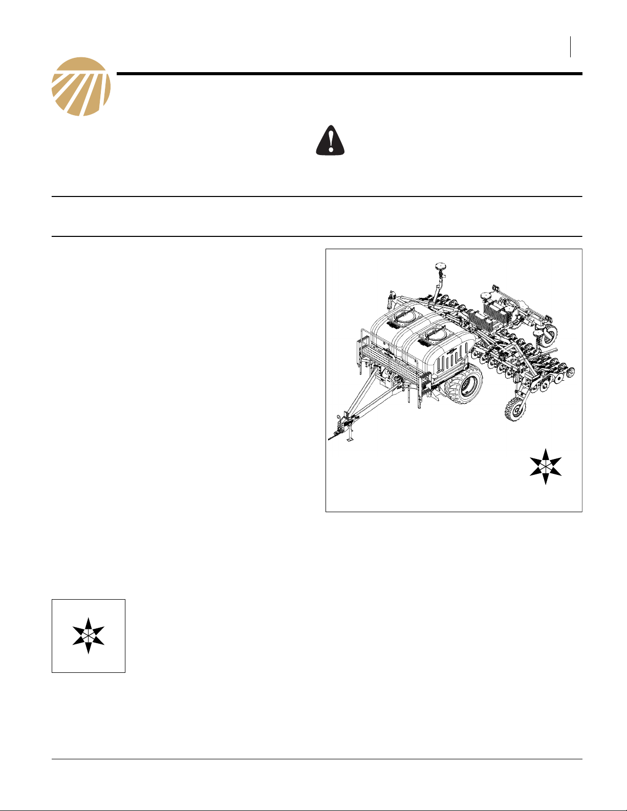
Figure 1
Standard (3 Weight) NTA607HD
R
F
U
B
L
D
31285
© Copyright 2010 Printed 12/02/2010 166-365M
Page 2
2 Great Plains Manufacturing, Inc. NTA607HD Lift Assist Adjustments
Important Safety Information
Look for Safety Symbol
The SAFETY ALERT SYMBOL indicates there is a
potential hazard to personal safety involved and extra
safety precaution must be taken. When you see this
symbol, be alert and carefully read the message that follows it. In addition to design and configuration of equipment, hazard control and accident prevention are
dependent upon the awareness, concern, prudence and
proper training of personnel involved in the operation,
transport, maintenance and storage of equipment.
Be Aware of Signal Words
Signal words designate a degree or level of hazard seriousness.
DANGER indicates an imminently hazardous situation
which, if not avoided, will result in death or serious injury.
This signal word is limited to the most extreme situations,
typically for machine components that, for functional purposes, cannot be guarded.
WARNING indicates a potentially hazardous situation
which, if not avoided, could result in death or serious
injury, and includes hazards that are exposed when
guards are removed. It may also be used to alert against
unsafe practices.
CAUTION indicates a potentially hazardous situation
which, if not avoided, may result in minor or moderate
injury. It may also be used to alert against unsafe practices.
Prepare for Emergencies
▲ Be prepared if a fire starts
▲ Keep a first aid kit and fire extinguisher handy.
▲ Keep emergency numbers for doctor, ambulance, hospital
and fire department near phone.
Be Familiar with Safety Decals
▲ Read and understand thoroughly.
▲ Read all instructions noted on the decals.
▲ Keep decals clean. Replace damaged, faded and illegible
decals.
166-365M 12/02/2010
Page 3
Important Safety Information Great Plains Manufacturing, Inc. 3
Practice Safe Maintenance
▲ Understand procedure before doing work. Use proper
tools and equipment.
▲ Work in a clean, dry area.
▲ Unfold and lower the drill, put tractor in park, turn off
engine, and remove key before performing maintenance. If
work must be performed with implement raised, use center
section lift lock and gauge lock channels provided.
▲ Make sure all moving parts have stopped and all system
pressure is relieved.
▲ Allow drill to cool completely.
▲ Disconnect battery ground cable (-) before servicing or
adjusting electrical systems.
▲ Welding: Disconnect battery ground. Protect hydraulic
lines. Avoid fumes from heated paint.
▲ Inspect all parts. Make sure parts are in good condition
and installed properly.
▲ Remove buildup of grease, oil or debris.
▲ Remove all tools and unused parts from air drill before
operation.
MetaData: End of <Safety Topics>
Null4:
12/02/2010 166-365M
Page 4
4 Great Plains Manufacturing, Inc. NTA607HD Lift Assist Adjustments
Before Starting
Dense Heavy Overhead Object Hazard:
Use adequate lifting means. Use both mounts for lifting.
Keep all workers clear of area while a weight is overhead.
Keep hands away from underside of weights, and out of stackto-stack contact regions. Weight stacks have a mass of 374kg
(825 pounds). A hoist failure could result in substantial equipment damage, serious injury or death. Hands in the path of
weight movement can be crushed.
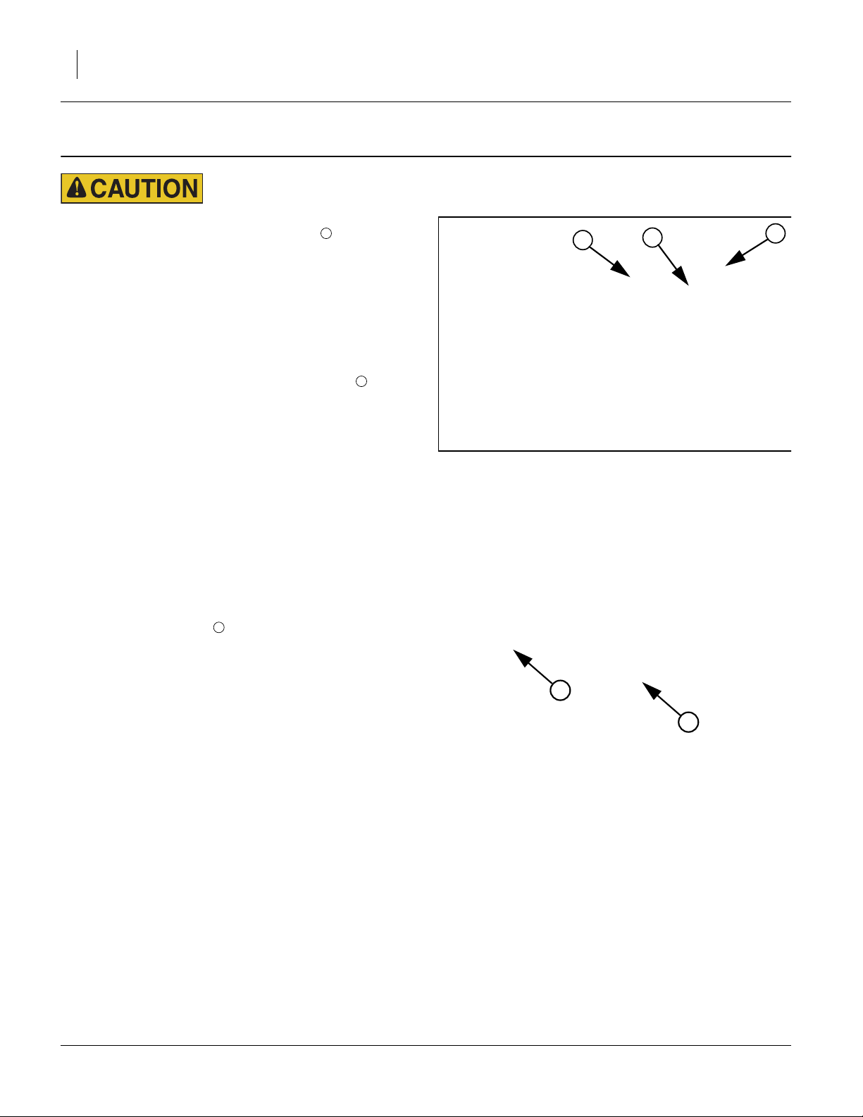
Refer to Figure 2 (6in 80-row model with blockage module)
There are three sets of weights bolted to the center
frame weldment. Remove the mid weight stack first.
This may be the only weight that needs to be removed if
it satisfactorily produces the result you desire. The only
way to judge the result is by running the unit in the field
once the weight is removed.
2
1
2
1
2
Null4:
Before Proceeding with Instructions
Refer to Figure 3
Check caster stabilizers are properly adjusted. It is
unlikely, but casters may want to swing out of position.
Stabilizer bolts should be adjusted tightly enough to
ensure this does not occur. See “Caster Brakes” in the
lubrication section of the Operator Manual (166-283M).
Do not set cart weight transfer higher than necessary.
Values close to 1000 psi can lift the rear of an empty cart
off the ground see “Cart Weight Transfer Adjustment
(Inner Valve)” on page 6.
3
Figure 2
Weight Stacks
3
3
Figure 3
Caster Stabilizers
166-365M 12/02/2010
Page 5

Remove Mid Weight Set Great Plains Manufacturing, Inc. 5
Remove Mid Weight Set
Refer to Figure 4 and Figure 5
1. Remaining clear of seed towers and hoses, disas-
semble mid weight set from the center frame
4
tubes .
1
2
Remove the1⁄2x11⁄2in bolt , hex nut and lock
washer from each top mount that hook the mid
weight and rear weight top mounts together.
(Retain bolt, nut and washer by securing them back
in the top mount holes of the mid weight after the
stack is removed.)
2. Remove the two weight bracket bolt channels that
keep the weights attached to the frame (only the left
one is visible in Figure 4). This requires removing the
nut and lock washer on the bottom of the bracket
securing each5⁄8x9in bolt .
When you take the nut off the bolt should slip out.
8
6
7
Before Proceeding:
The individual weight bars, two top mounts and long
weight mount channel weldment remain assembled as
one unit.
3. There are two weight bracket mounts on the top of
each stack of weights. Secure lifting hooks or chains
to these two mounts on the mid weight. (Take up
slack gradually to avoid deforming mounts. Minimize
load sway to avoid damage to nearby objects and the drill.)
4. Hoist mid weight up and away from implement. Place
in storage along with the two weight bracket bolt
channels (Note: channels may be used later).
6
5
2
2
R
F
1
U
D
2
4
4
B
L
Figure 4
Remove Mid Weight Stack
8
7
5
6
31736
Adjust Back Pressure
5. To manipulate the amount of down force:
In addition to removing the mid weight stack you will
need to adjust the back pressure at the pressure
reducing valve located on the left wing. See “Adjust
Weight Transfer Valves” on page 6.
Figure 5
Place Hooks on Top Weight Mounts
12/02/2010 166-365M
Page 6

6 Great Plains Manufacturing, Inc. NTA607HD Lift Assist Adjustments
Adjust Weight Transfer Valves
Refer to Figure 6 and Figure 7
Do not set cart weight transfer higher than necessary. Values
close to 1000 psi can lift the rear of an empty cart off the
ground. As a cart nears empty, the main tires can begin to slip,
or stop turning altogether, resulting in irregular seeding rates
or stoppages.
Wing Weight Transfer Adjustment (Outer Valve)
Note: This valve will most likely not need adjusting. It will
already be set to meet your requirements.
1. Release lock ring on wing-transfer valve .
Adjust knob while observing gauge .
Increase weight transfer to wings by turning knob
clockwise. Reduce weight transfer to wings by turning knob counter-clockwise.
Set pressure to at least 250 psi.
Secure setting with lock ring.
3 1
4 5
Cart Weight Transfer Adjustment (Inner Valve)
Note: This valve will need adjusting to get the results
you require.
2. Release lock ring on cart-transfer valve .
Adjust knob while observing gauge .
6 2
7 8
8
2
5
1
6
3
7
4
Figure 6
Pressure Reducing Valve
Inner Valve Controls Cart
Outer Valve Controls Wings
To avoid planting problems, do not exceed 1500 psi for wingtransfer, and 1000 psi for cart-transfer. A relief valve prevents
operating the wing-transfer at over 1500 psi.
31192
Increase weight transfer from cart by turning knob
clockwise. Reduce weight transfer from cart by turning knob counter-clockwise.
Set pressure to at least 100 psi.
Secure setting with lock ring.
3. Pull forward in ground. Assess opener penetration,
and coulter (option) penetration. Compare wings to
center section.
4. During field operations, monitor coulter and opener
depth of wings and center section. Adjust weight
transfer as required for consistent depth across drill.
5. Once the cart weight transfer has been adjusted,
adjust the rear lift assist adjustment linkage as
described in “Adjust Linkage” on page 7.
Figure 7
Pressure Reducing Valve Decals
Cart: Decal on Left
Wing: Decal on Right
166-365M 12/02/2010
Page 7

Adjust Linkage Great Plains Manufacturing, Inc. 7
Adjust Linkage
Refer to Figure 8
The factory setting of the lift assist link has approximately
7.62cm (3in) of exposed threads outside the fixed end of
the lift assist link. Adjust the link (extend it out) by only
2.54cm to 3.81cm (1 to 11⁄2in). Anymore than that could
be unsafe and lead to machine damage.
Caster Failure Hazard:
Never exceed 13.97cm (51⁄2in) of exposed threads on the lift
assist adjustment link. Exceeding this measurement could
result in linkage failure leading to severe machine damage,
bodily injury or death.
1. With drill (unfolded and lowered) place a jack stand
underneath the rear part of the frame near the caster
wheels. Support is required to take weight off the
casters for ease of adjustment. If you do not have a
jack stand, an alternative method to reduce weight
on the casters is to do the following four steps:
• turn the 90 degree ball valve on the fan to transport position
• activate the tractor remote lever to supply oil to
the fan/weight transfer circuit
• set the cart weight transfer to 100 psi
• set the wing weight transfer to the maximum
pressure setting of 1500 psi.
2. Measure from the inside face of the square nut to
the inside face of the adjuster nut (see Figure 8).
2
1
The factory setting is approximately 7.62cm (3in).
Adjust it out 2.54cm (1in) to start with. The measurement from the face of the square nut to the face of
the adjuster nut will now be 10.16cm (4in).
3. Determine if adjusting the link 2.54cm (1in) provides
a satisfactory result. See “Determine Results” on
page 8. If frame drops back too much it indicates
there is still too much weight. Follow instructions for
removng rear weight set.
Adjust Lift Assist Link
2
Figure 8
1
Null4:
31747
12
Null4:
31755
Link Adjust
factory set 7.62cm (3in)
2.54cm (1in) 10.16cm (4in)
3.81cm (1.5in)
5.08cm (2in) 12.7 (5in)
6.35cm (2.5in)
12/02/2010 166-365M
Thread
Measurement
11.43cm
(4.5in)
13.97cm
(5.5)in
PW Transport
Clearance
27.94cm (11in)
22.86cm (9in)
20.32cm (8in)
17.78cm (7in)
less than12.7cm
(5in)
Comments Casters
factory setting
moves casters 10.16cm (4in)
more than factory setting
maximum recommended link
adjustment
not recommended
start losing PW clearance
NEVER EXCEED UNSAFE thread engagement not enough
moves casters 15.24cm (6in)
more than factory setting
moves casters 20.32cm (8in)
more than factory setting
for safe transport
Page 8

8 Great Plains Manufacturing, Inc. NTA607HD Lift Assist Adjustments
Determine Results
1. Run implement in field.
2. If removing the mid weight stack satisfactorily gets
the result you desire (the tires are off the ground as
you want) you are done. Make sure to reset valve:
back pressure must be set to at least 100 psi.
3. If the result is not satisfactory and further adjustment
is desired it will be necessary to set the pressure
back down and then proceed with the rest of these
instructions to remove the rear set of weights.
Insufficient Opener Weight Risk:
It is not recommended to remove the front weight stack. If the
implement is used in heavier till field conditions there will be
insufficient down force over the coulters for penetration in the
soil.
166-365M 12/02/2010
Page 9

Remove Rear Set of Weights Great Plains Manufacturing, Inc. 9
Remove Rear Set of Weights
Refer to Figure 9
About the Weights
The 6in 80-row drill model has an extra (fifth) blockage
module that the other models (6in 40-row, 7.5in 32-row,
7.5in 64-row) do not require. It is mounted on the double
shoot blockage module mount on the rear set of
weights . It needs to be dismantled and moved as per
the following instructions. If the implement you have does
not have this mount bracket, disregard references to it
and follow all other instructions.
13
12
11
13
14
12
11
Remove Rear Weight Set
1. If you have the double shoot 6in 80-row model:
Remove double shoot blockage module mount
keeping DICKEY-john® module attached and save
along with any hardware to remount. This will be
remounted in Step 5 to the angle tower bracket.
2. Remove the5⁄8x9in bolts at either end of the two
center tower mount brackets that the rear weight
13
stack is bolted to (only left frame side is visible in
Figure 9). The U-bolt remains permanently
attached.
3. Secure lifting hooks or chains to the two mounts
on the top of the rear weight stack. (Take up slack
gradually to avoid deforming mounts. Minimize load
sway to avoid damage to nearby objects and the
drill.)
4. Hoist rear weight stack up and away from implement and place in storage along with all associated
hardware.
15
14
16
13
Reattach Mount Bracket and Module
Refer to Figure 10 and Figure 11
5. If you have the double shoot 6in 80-row model:
Attach double shoot blockage module mount
bracket with attached DICKEY-john® module
to upper set of holes in double shoot tower mount
angle bracket (Figure 10) using two bolts currently in place on the tower bracket.
Note: This bracket must be centered to connect to all
12 17
18
seed hoses.
12
11
R
F
U
D
B
L
15
Figure 9
Rear Weight Stack
17
18
14
16
31738
12
6
6
Figure 10
Blockage Monitor Mount Bracket
12/02/2010 166-365M
Page 10

10 Great Plains Manufacturing, Inc. NTA607HD Lift Assist Adjustments
Reattach Bolt Channel Brackets
6. Take the two weight bracket bolt channels and two
5
⁄8x9in bolts per bracket that were removed from
the bottom of the mid weight set and remount one
each on top of the left and right frame tubes as pictured (Figure 10 and Figure 11).
15
6
6
Adjust Back Pressure
7. To manipulate the amount of down force:
In addition to removing the rear weight stack you
should adjust the back pressure at the pressure
reducing valve located on the left wing See “Adjust
Weight Transfer Valves” on page 6.
15
6
Null4:
Determine Results
1. Run implement in field.
2. If removing the rear weight stack satisfactorily gets
the result you desire (the tires are off the ground as
you want) you are done. Make sure to reset pressure valve: back pressure must be set to at least
100 psi.
Insufficient Opener Weight Risk:
It is not recommended to remove the front weight stack. If the
implement is used in heavier till field conditions there will be
insufficient down force over the coulters for penetration in
the soil.
R
F
U
B
L
D
Figure 11
Weight Bracket Bolt Channels
15
166-365M 12/02/2010
Page 11

Appendix Great Plains Manufacturing, Inc. 11
Appendix
Abbreviations
in. inch/inches PW press wheel
kg kilograms W/ With
psi pounds per square inch X by
12/02/2010 166-365M
Page 12

12
Great Plains Manufacturing, Inc.
Corporate Office P.O. Box 5060
Salina, Kansas 67402-5060 USA
166-365M 12/02/2010
 Loading...