

Page 1
Great Plains Mfg., Inc.
Blockage Monitor Kits
Air Drills
Used with:
• 3N-4010HDA
• CTA4000 and CT4000HD
• NTA3010 and NTA3510
General Information
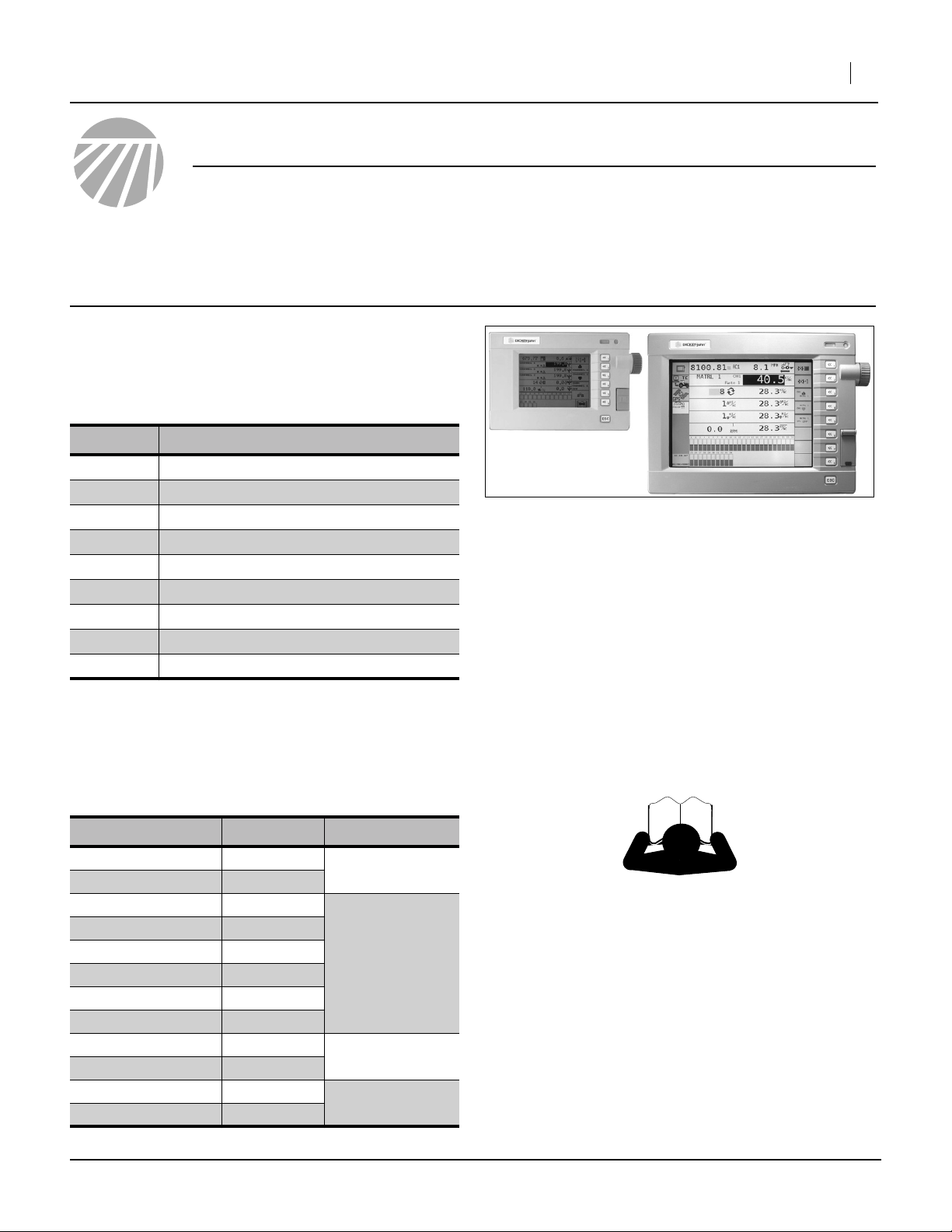
Blockage monitor kits upgrade the existing DICKEY-john
Intelli-ag AirCart Controlsystem,adding the capability to
detect extreme variations in seed flow to individual rows.
These instructions explain how to install any of the following Blockage Monitor Kits:
Kit Kit Description
168-404A NTA30-4875 DICKEY JOHN BLOCKAG
168-405A NTA30-3610 DICKEY JOHN BLOCKAG
168-406A NTA35-5575 DICKEY JOHN BLOCKAG
168-407A NTA35-4010 DICKEY JOHN BLOCKAG
168-408A CTA40-8006 DICKEY JOHN BLOCKAG
168-409A CTA40-6575 DICKEY JOHN BLOCKAG
168-410A CTA40-5010 DICKEY JOHN BLOCKAG
168-411A 3N40HD-6675 DICKEY JOHN BLOCK
168-412A 3N40HD-4810 DICKEY JOHN BLOCK
If installation is being done on a new 3N-4010HDA, use
the instructions in the 196-444Q Pre-Delivery manual.
The instructions in this manual (168-414M) presume a
drill originally delivered and setup without blockage.
Each kit updates one drill. Kits are specific to drill models
and row spacings:
Installation Instructions 1
Figure 1
Existing Intelli-ag Console
Note: The air drill must already be equipped with a
DICKEY-john Intelli-ag Air Cart Control system,
which includes a 5in or 10in LCD console (shown
above) for the tractor cab. This system is standard
with the ADC2350 and ADC2350B air drill carts.
Air drills using ADC1150, ADC2220and ADC2250
carts, and equipped with Loup monitor systems,
cannot use these blockage kits.
25421
Air Drill Models Use Kit Pages
3N4010HDA-4810
3N4010HDA-6675
CTA4000-5010
CTA4000HD-5010
CTA4000-6575
CTA4000HD-6575
CTA4000-8006
CTA4000HD-8006
NTA3010-3610
NTA3010-4875
NTA3510-4010
NTA3510-5575
©Copyright 2008 Printed 10/29/2008 168-414M
168-412A
168-411A
168-410A
168-410A
168-409A
168-409A
168-408A
168-408A
168-405A
168-404A
168-407A
168-406A
2-9, 29
2-3, 10-16, 29
2-3, 17-22, 29
2-3, 23-29
Before You Start
Review these instructions, with the following objectives:
• Compatibility: make sure the correct kit has been
ordered, and the air drill has the necessary DICKEYjohn Intelli-ag Air Cart Control system.
• Inventory: make sure all parts are present.
• Comprehension: make sure the installers understand
where each part is installed, and what tools are
required for the task.
Page 2
2 Blockage Monitor Kits
Notati
Great Plains Mfg., Inc.
Tools Required
• Current Operator manual:
3N4010HDA 196-444M
CTA4000 160-269M-A
CTA4000HD 160-037M
NTA3010 160-219M-A
NTA3510 160-219M-A
• Updated Parts manual:
3N4010HDA 196-444P
CTA4000 160-269P
CTA4000HD 160-037P
NTA3010 160-219P
NTA3510 160-219P
• tractor or hydraulic power source, and;
• basic hand tools, including a power drill and
11
3
⁄
to
⁄
16
in (17-19mm) hole saw.
4
ons and Conventions
“Left” and “Right” are facing in the
direction of machine travel. An orientation rose in the line art illustrations
shows the directions of Left, Right,
Front, Back, Up, Down.
Call-Outs
1 9
to ,
a z
to
11 40
to
91 98
to
Single-character callouts identify components in the currently referenced Figure or
Figures. These numbers may be reused for
different items from page to page.
Two-digit callouts in the range 11 to 40 reference new parts from the new parts list on
page 40. The descriptions match those on
the parts, bags or cartons, and in your
updated Parts Manual.
Two-digit callouts in the range 91 to 98 reference existing parts from the list on page 41.
The descriptions match those your Parts
Manual.
U
F
L
R
B
D
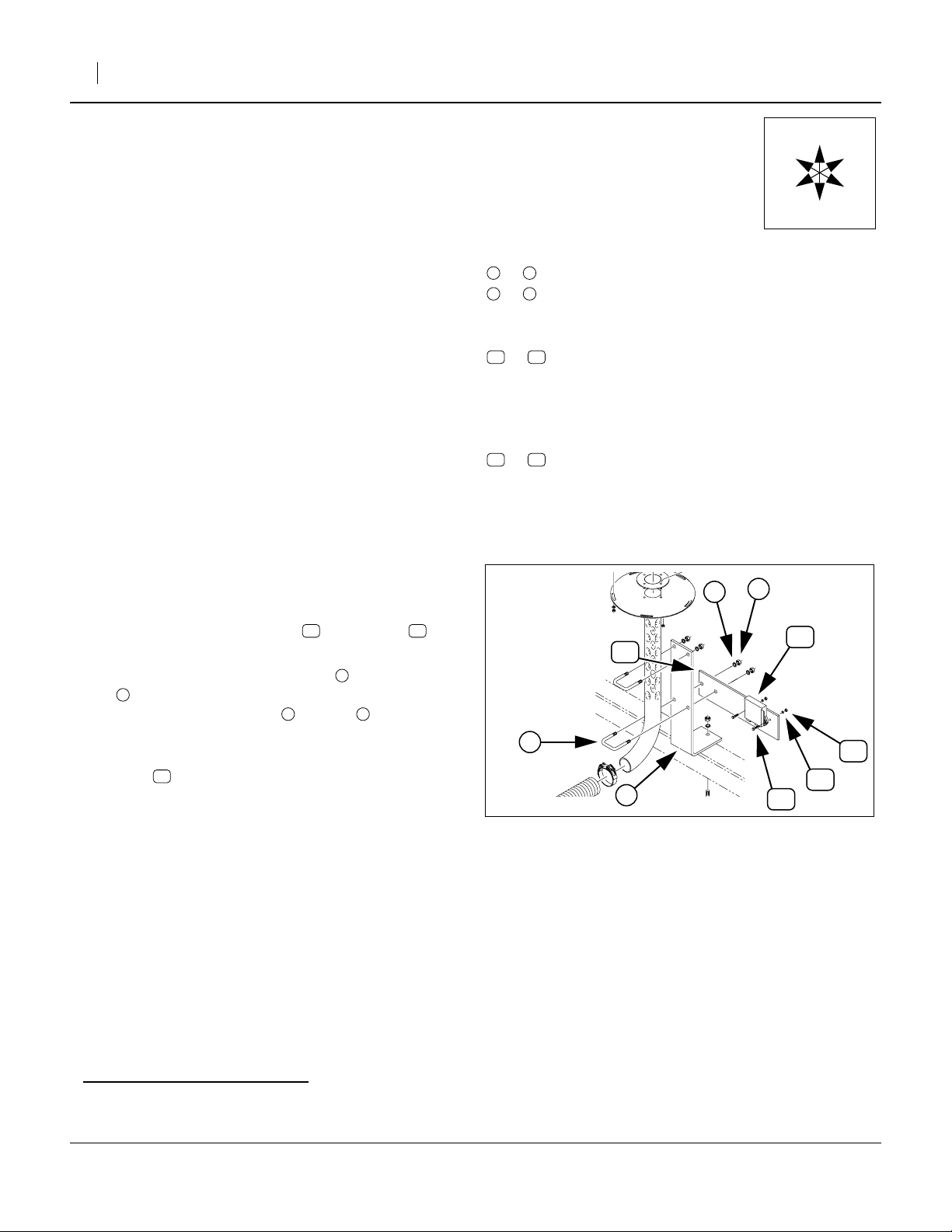
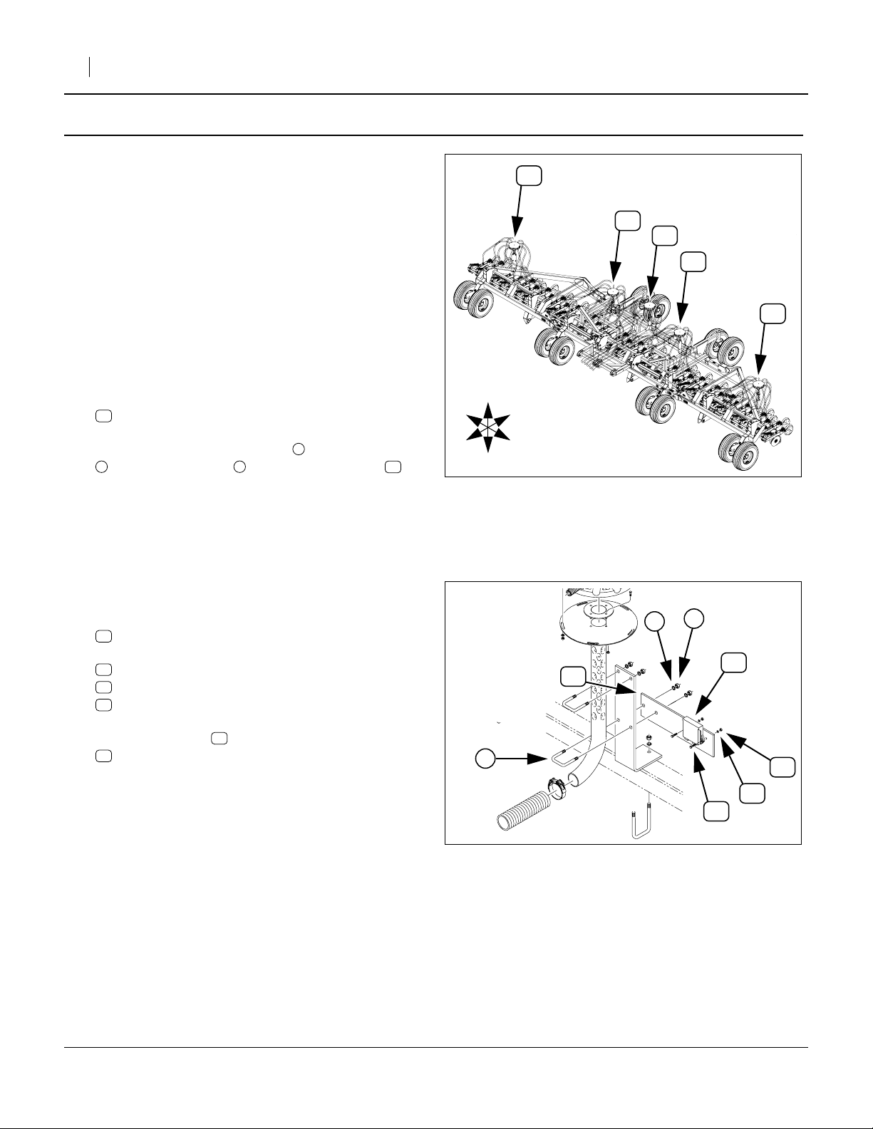
Mount and WSMBa Orientation
Refer to Figure 2
The kit includes a mounting plate and WSMB for
each tower.
The plate attaches to the tower mount , at an existing
U-bolt located just above the bend in the tower tube,
and under the existing washer and nut . The plate
orientation (left, right, front or back) is described in the
detailed steps.
The WSMB mounts to the tower side of the plate, with
mount ears flat against the plate, and connectors facing
down.
2
39
12 39
1
3 4
4
3
39
12
2
15
16
1
Figure 2
Typical Module Mount
14
27058
a. WSMB: DICKEY-john Working Set MemBer module
168-414M 10/29/2008
Page 3
Great Plains Mfg., Inc.
Pre-Assembly Preparation
Work Location
1. Move the drill to a location with:
• room to unfold it,
• adequate illumination, and;
• a clear surface beneath for recovery of any
dropped parts.
Prepare Drill
2. Position the drill at the work location.
3. Unfold the drill.
4. Lower the row units.
5. Set tractor hydraulic remotes to Float, to relieve
pressure in the lines.
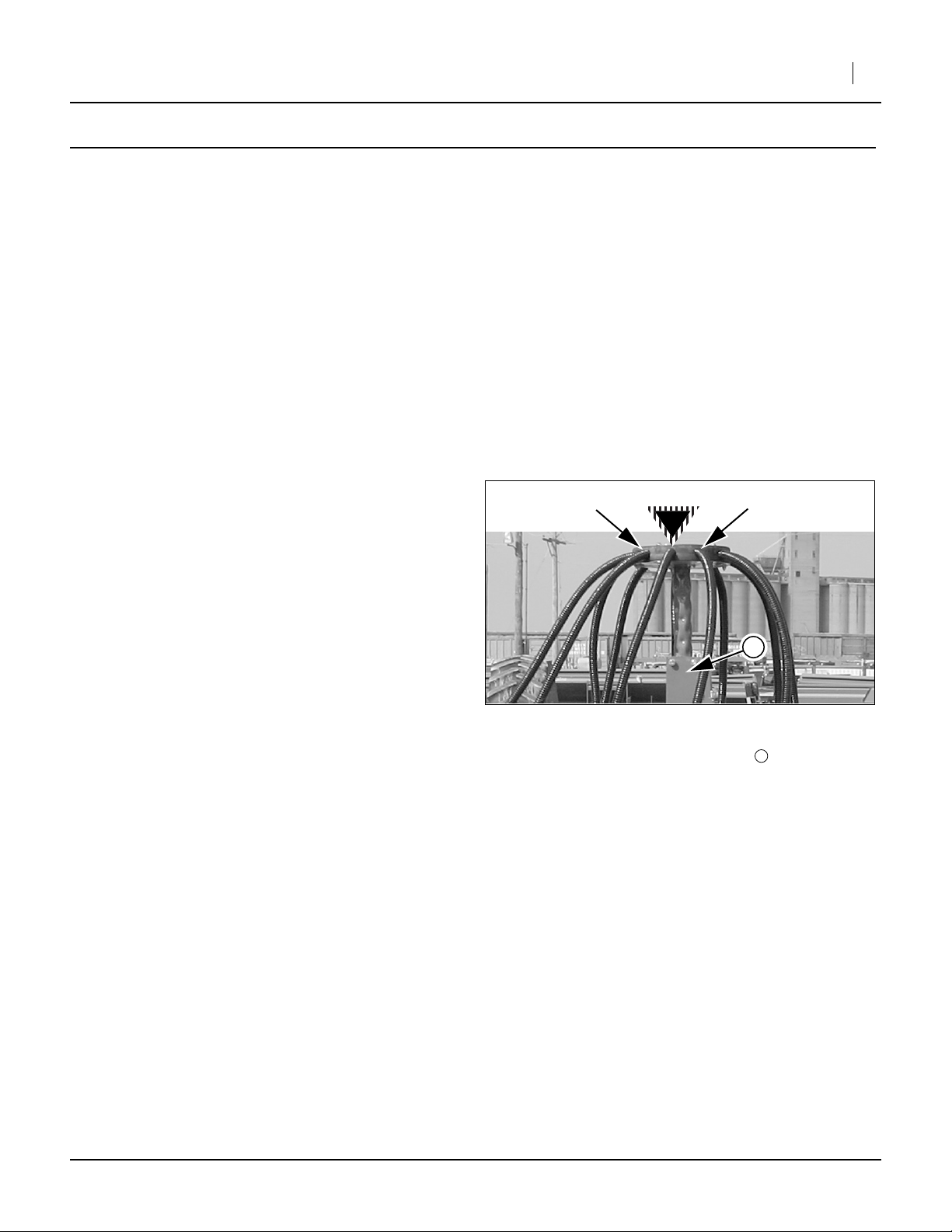
Port Numbering
Tower Ports are numbered Clockwise from mount center
(Port 1) to the last port number, which is the same for all
towers on the same drill.
As an aid to installation, mark the port numbers after
checking Port 1. If the tower weldment has shifted position since initial delivery, Port 1 may not be exactly at the
mount.
PORT 2
Installation Instructions 3
PORT
1
PORT 8, 9, 10, 11,
12, 13 or 16
Refer to Figure 3
6. Verify Port 1. Consult the Port Assignments table
for the drill and row spacing (found in the Appendix
of this manual). The first Opener entry in the table is
Port 1. Openers are numbered from 1 at drill left.
Follow the seed hose from that opener to the tower.
This is Port 1.
7. Mark the Port numbers on the tower cap, moving
clockwise (looking down on the cap) from Port 1.
8. Turn to pages for your drill:
3N-4010HDA Installation.....................................page 4
CTA-4000 and 4000HD Installation...................page 10
NTA-3010 Installation........................................page 17
NTA-3510 Installation........................................page 23
Figure 3
Tower Port Numbering
Facing Tower At Mount
m
28185
m
10/29/2008 168-414M
Page 4
4 Blockage Monitor Kits
3N-4010HDA Installation
This installation requires one of the following kits:
168-411A 3N4010HDA-6675 (66 row, 7.5in)
168-412A 3N4010HDA-4810 (48 row, 10in)
If installation is being done on a new 3N-4010HDA, use
the instructions in the 196-444Q Pre-Delivery manual.
The instructions in this manual (168-414M) presume a
drill originally delivered and setup without blockage.
Additional installation information is found in the
DICKEY-john IntelliAg Air Cart Control Operator’s manual.
Note: The DICKEY-john manual has only general har-
ness routing for the Great Plains air drills, and
somecable part numbers areslightly differentfrom
those in the kits.
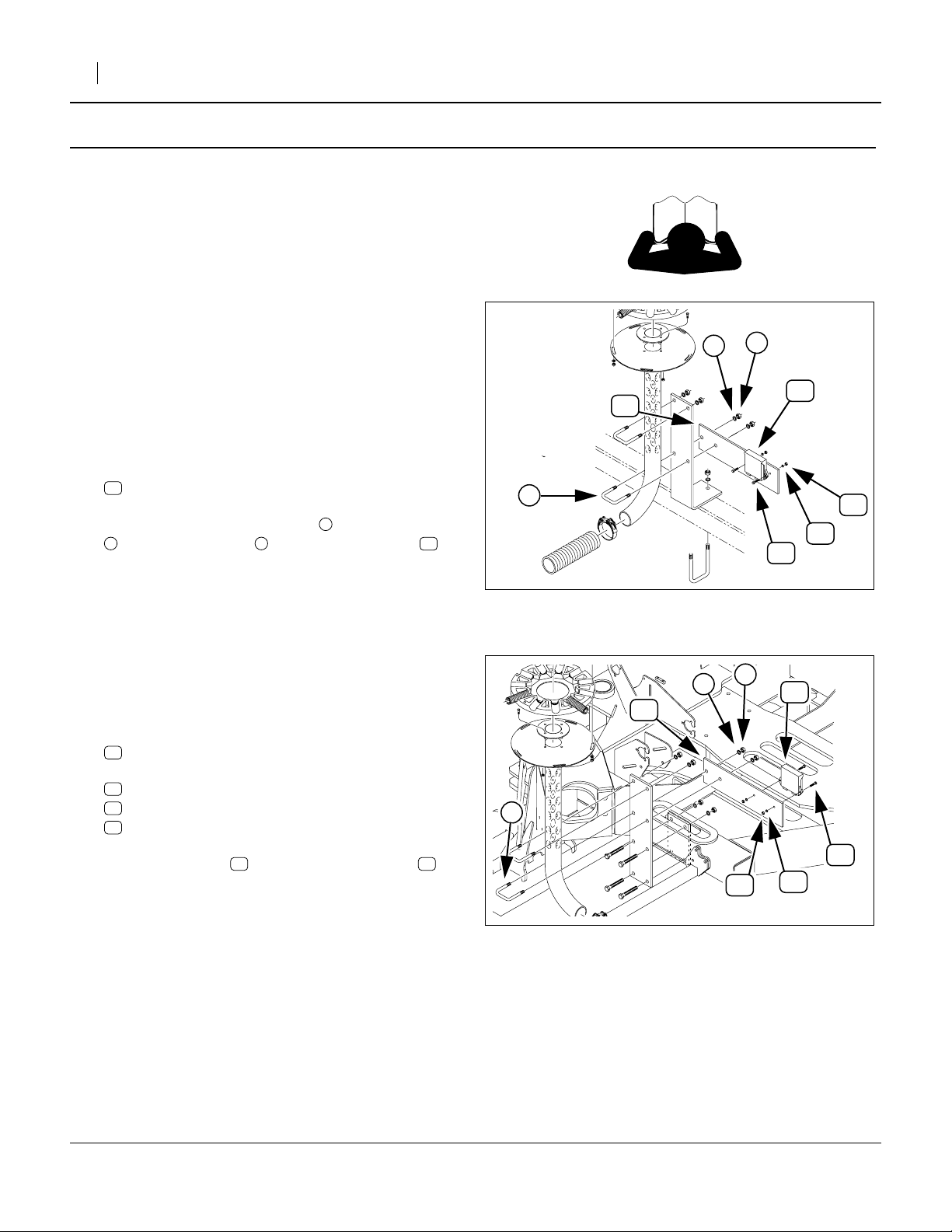
Refer to Figure 4 and Figure 5
9. Select six (6):
12
168-465D DIST TOWER MODULE MOUNT PLATE
At each tower, remove the nuts andlock washers
2 312
at the lower U-Bolt , and mount the plate .
Plate orientation is small holes to top, and:
on Towers 1 & 6: extension to drill center
on Towers 2 & 5: extension away from drill center
on Towers 3 & 4: extension to drill rear
1
Great Plains Mfg., Inc.
1
2
39
12
3
15
16
14
Figure 4: 3N:
Tower 2 Module Mount
27058
3N: Install WSMBs
Start with the left tower (Tower 1).
Refer to Figure 4 and Figure 5
10. Select one:
39
467981100S1 INTAG WSMB/FLW MNTR MODULE 18R
and two sets:
14
802-224C HHCS 1/4-20X1 1/4 GR5
16
804-006C WASHER LOCK SPRING 1/4 PLT
15
803-006C NUT HEX 1/4-20 PLT
Mount the WSMB on the front of the plate ,
with the connector ports down.
11. Repeat step 10 for the remaining towers.
The WSMB orientation is:
on Wing towers (Figure 4):
connectors down, module to front
on Center towers (Figure 5):
connectors down, module to center
39 12
1
2
39
12
3
14
15
Figure 5: 3N
Tower 3 Module Mount
16
28182
168-414M 10/29/2008
Page 5

Great Plains Mfg., Inc.
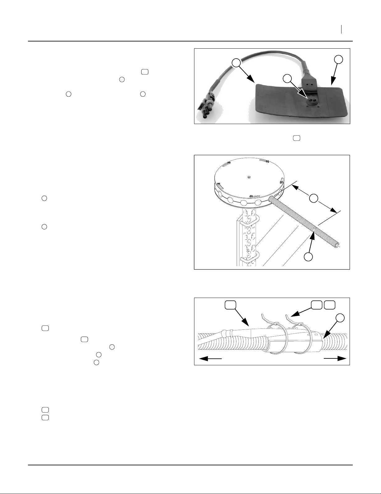
3N: Prepare Hoses for Sensors
Refer to Figure 6
DICKEY-john Recon-II blockage sensors require a
hole in the hose for the detectors . The sensor has flex-
1
ible flaps which are tie-wrapped around the seed hose.
The long flap goes over the short flap .
2 3
Note: Usea holesawto makethehole. Use a high speed
drill (to minimize rough edges), and cut slowly (to
minimize risk of drill-through).
30
Installation Instructions 5
2
3
1
Using a drill bit is likely to damage the hose.
Refer to Figure 7 (showing hole on top)
12. Drill one hole in each secondary seed hose at each
tower. Check the first hole for sensor fit before drilling the remaining holes.
The hole location is approximately:
4
13in (33cm)
from where the hose enters the tower.
The hole diameter is:
11
5
3
⁄
to
⁄
16
in (17-19mm)
4
Make the hole on the underside of the hose (toward
center of tower), or rotate the hose to hole-under
after drilling or installing sensor.
3N: Install Blockage Sensors
Refer to Figure 8 and Figure 6
13. Select one:
30
467420352S1 RECON II
Figure 6: 3N
Blockage Sensor
30
4
5
Figure 7: 3N:
Sensor Hole Location
30 26 27
28197
28194
2
14. Orient sensor with signal lead toward opener.
Insert the detector head in the hose hole.
Wrap the short flap around the hose.
Wrap the long flap over the short flap.
Check that the long flap overlaps by at least
30
1
3
2
1
⁄
in
4
Opener
Figure 8: 3N:
Mount Sensor
Tower
28195
(6mm), but by no more than 1in (25mm). If the flap
is too long, cut off any excess. Re-check overlap.
15. Select two ties from either:
26
110110050 TY WRAP BUNDLE 50-14"
27
110110099 TY WRAP BUNDLE 100-14"
Secure the sensor to the hose with ties.
10/29/2008 168-414M
Page 6
6 Blockage Monitor Kits
Great Plains Mfg., Inc.
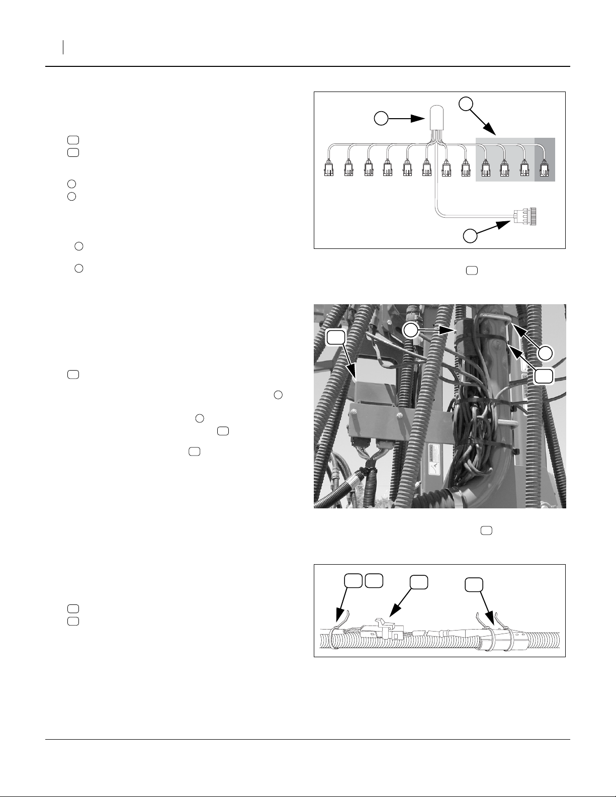
3N: Mount Row Harnesses
Start with Tower 1 (left wing, left tower).
Refer to Figure 9
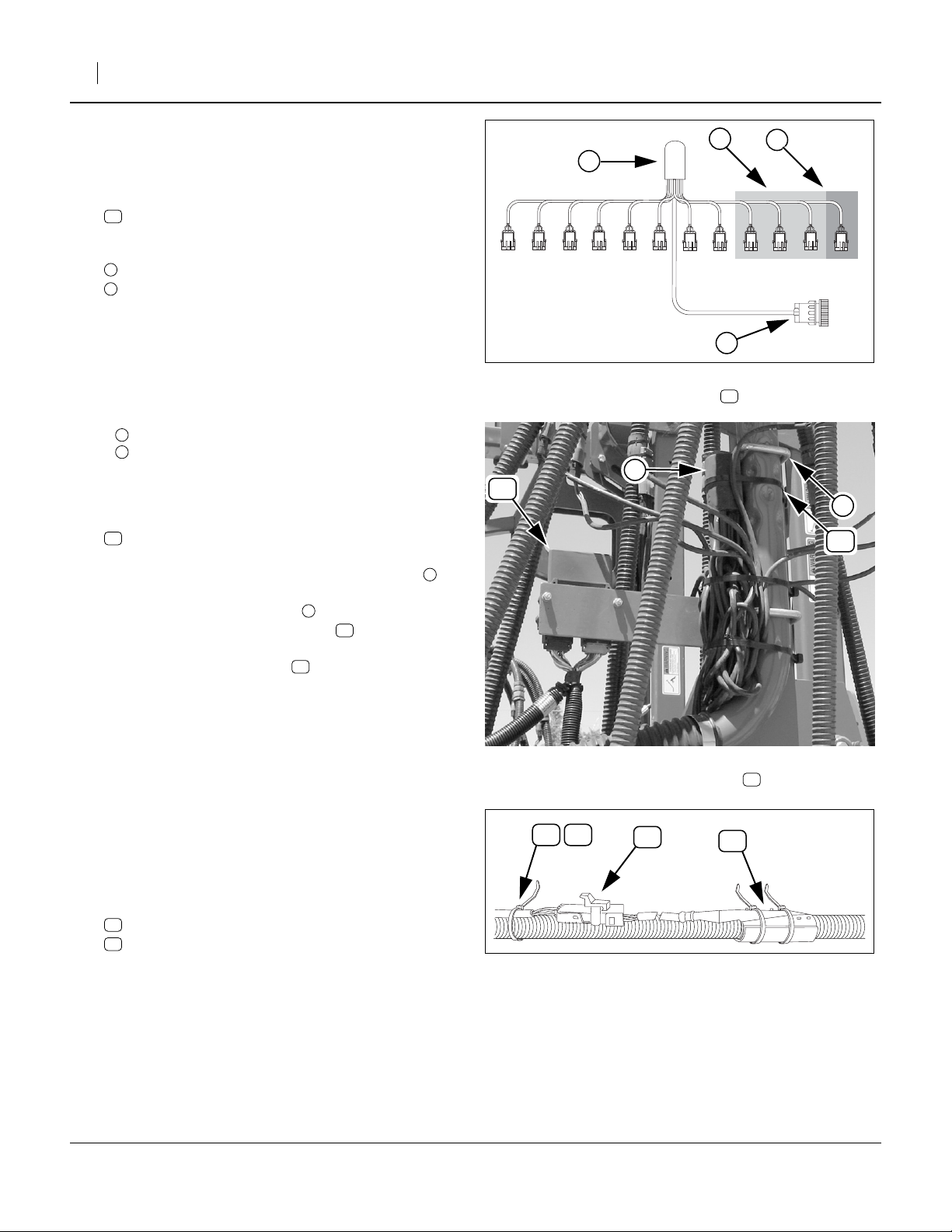
16. Select one:
31
467751320S1 12 ROW HARNESS
Observe that the assembly has:
1
one large connector (for the WSMB);
2
a sealed weather-cap module; and,
12 row sensor connectors,
numbered “ROW 1” through “ROW 12”
Note: Connector numbering matches harness-to-row
only on Tower 1. At connection step 19, see “Port
Assignment” table on page 31 or page 32.
Note: There are more sensor leads than drills rows.
3
“ROW 12” is unused on 3N-4010HDA-6675.
4
“ROW 9” through “ROW 12” are unused on
3N-4010HDA-4810.
Refer to Figure 10
17. Select one:
13
800-082C CABLE TIE .31X21.5 6DIA 120LB
At the tower, position the weather-cap module :
- lead bundle down,
- just under the upper U-bolt , and;
- on the same side as the WSMB .
3
39
4
3
2
1
345678
2
10 11 12
9
1
Figure 9: 3N:
Row Harness
31
28198
2
39
3
13
2
Secure the module with tie around the tower
weldment and mounting plate.
18. Repeat step 16 and step 17 for Tower 2 through 6.
13
3N: Sensors to Harnesses
Start with opener 1 (left opener, left wing).
Refer to Figure 11
19. Using the table on page 31 or 32, determine the
Harness lead (“ROW”) to tower Port assignment.
Isolate each lead from the bundle, and plug the
assigned harness lead and sensor cable together.
20. Select one tie from either:
26
110110050 TY WRAP BUNDLE 50-14"
27
110110099 TY WRAP BUNDLE 100-14"
Tie the harness lead to the same seed hose as its
assigned sensor. Tie about 1in (2.5cm) behind the
cable sheath
21. Repeat step 19 and step 20 for each port on the
tower, and then for each tower. One or four leads
per tower are not connected. Excess cable is tiewrapped at step 25.
26 27
Figure 10: 3N:
Install Row Harness
31
Figure 11: 3N:
Row Harness to Sensor
31
30
28199
28196
168-414M 10/29/2008
Page 7
Great Plains Mfg., Inc.
Installation Instructions 7
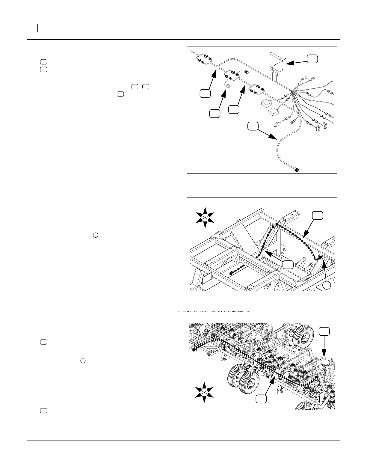
3N: Salvage Harness
Refer to Figure 12
The existing monitor harness on the drill simply routes
the bus from front to rear hitch, and consists of three
cable assemblies. The blockage sensor system “splices”
into the harness. Two existing cables are re-positioned.
22. Remove and save:
93
467980141 10’ EXT HARNESS
23. Locate cable:
92
467980130 40’ HITCH HARNESS
Leave it secured to the tongue, but release it from
straps or ties on the drill frame.
Note: The rear hitch cable:
94
467980360 3’ REAR HITCH HARNESS
is left in place.
3N: Install WSMB Harnesses
Start with Tower 1 (left wing, left tower)
Refer to Figure 13
24. Select one:
40
467981201 INT AG HARNESS, WSMB MOD-
ULE
31
93
92
R
F
Figure 12: 3N:
Harness Route (w/o Blockage)
30
94
U
B
L
D
28443
39
Join the row harness connector to the mating
connector on the row harness .
Plug the WSMB connectors into the WSMB .
These connectors are not interchangeable, and are
keyed to ensure correct insertion.
Refer to Figure 10 on page 6
25. Select two:
13
800-082C CABLE TIE .31X21.5 6DIA 120LB
Coil up excess rowharness leads and tie the bundle
to the tower, above and below the lower U-bolt.
26. Repeat step 24 and step 25 for each tower.
1
31
239
R
U
D
2
5
40
L
1
3
4
Figure 13: 3N:
WSMB Harness
40
28200
10/29/2008 168-414M
Page 8
8 Blockage Monitor Kits
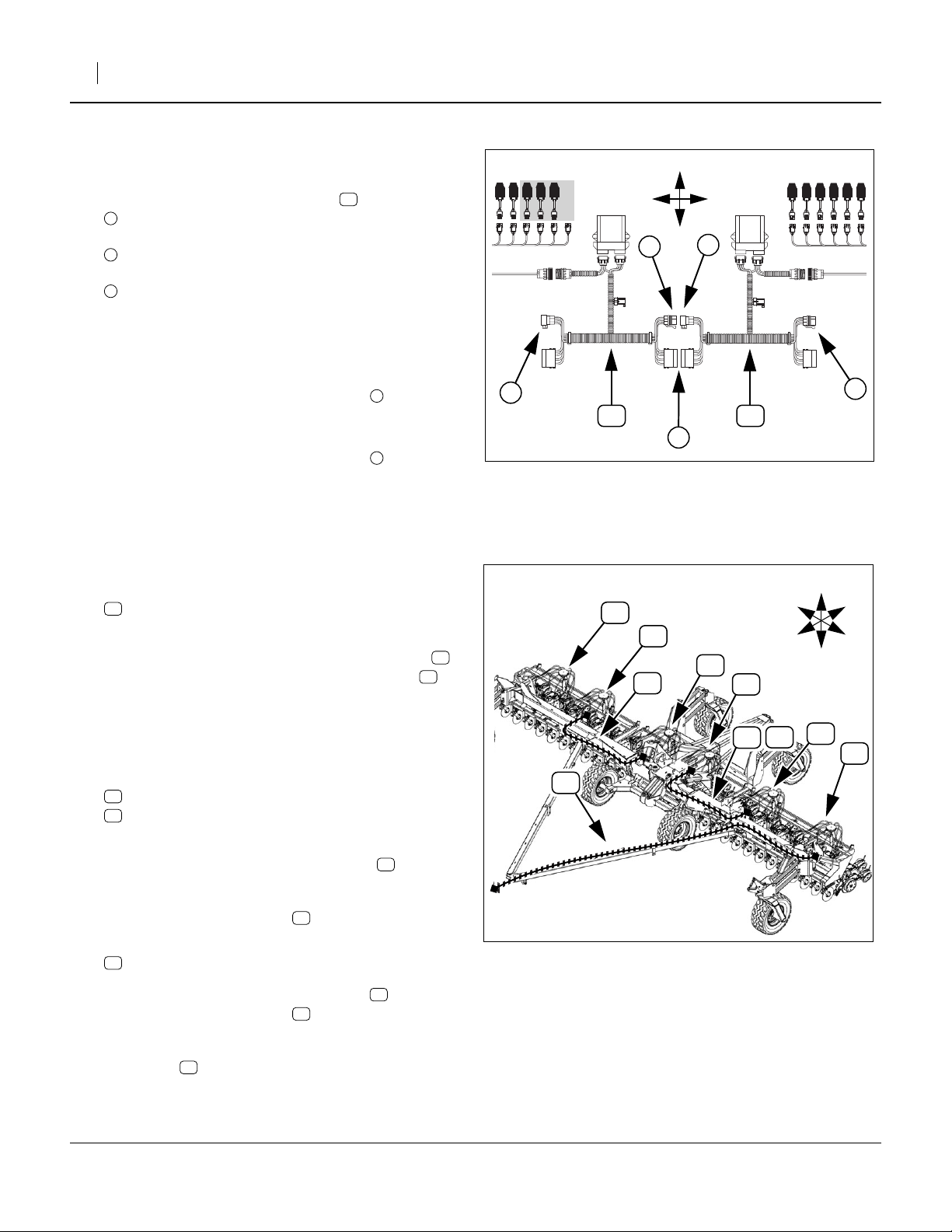
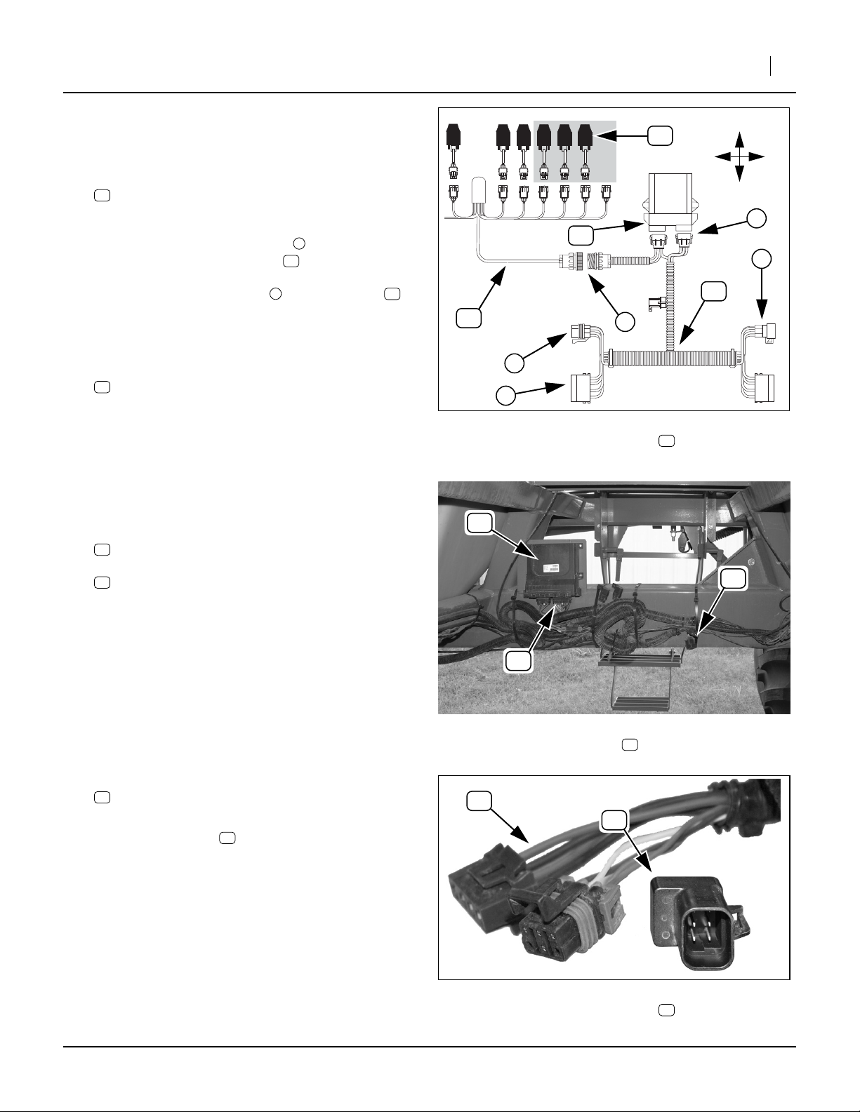
3N: Interconnect WSMBs
Start with the left wing.
Refer to Figure 14
27. At the left wing WSMB harnesses , interconnect
3
the female (receptacle) of left (outer) CAN bus
with
5
the male (plug) end of the mid-wing CAN bus.
Also connect the
4
power receptacle and plug
Note: The unconnected mid-wing CAN bus connector,at
right (near drill center) must be a receptacle.
28. At drill center, interconnect the center WSMB harnesses as shown in Figure 14, so that the free end
of the CAN bus at right is a receptacle .
29. At the right wing, interconnect the wing WSMB harnesses as shown in Figure 14, so that the free end
of the CAN bus at right is a receptacle .
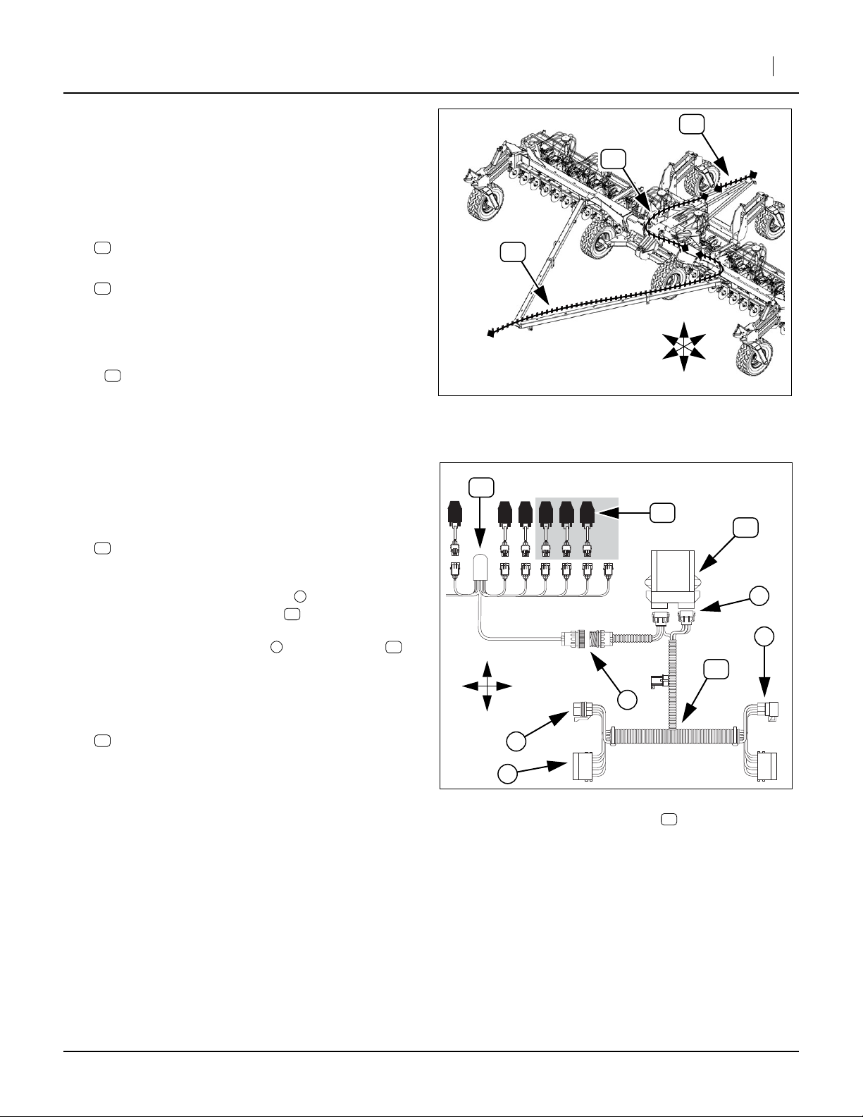
3N: Route Drill Harness
When routing harness extensions, allow slack at towers for raising and lowering.
40
3
5
40
3
Left Wing Interconnect
U
D
R
5
L
3
4
Figure 14: 3N:
Great Plains Mfg., Inc.
3
40
28201
3N: Route Front Hitch Harness
Refer to Figure 15 and Figure 16 on page 9
30. Locate the rear end of:
92
467980130 40’ HITCH HARNESS
released at step 23.
Route the free rear end of this cable to Tower 1 ,
and connect it to the Tower 1 WSMB harness .
Secure hitch harness and Tower 1 WSMB harness
with ties.
3N: Route Wing Harnesses
31. Select one saved and one new:
93
467980141 10’ EXT HARNESS
35
467980141 10’ EXT HARNESS
Plug cables together. Connect plug end of the
assembly to WSMB harness at Tower 2 (left mid-
wing). Route the harness through the hoop at the
left wing pivot. Connect the receptacle end to the
WSMB harness at Tower 3 (left side of center).
32. Select one new:
34
467980140 DJ 20’ HARNESS EXT
Connect the plug end of the extension to the
WSMB harness at Tower 4 (right center). Route
the harness through the hoop at the right wingpivot.
Connect the receptacle end to the WSMB harness
at Tower 5 (right mid-wing).
T5
T3
T4
T2
34
40
T1
T6
T5
T4
34
T3
93
92
Figure 15
Blockage Harness Route (1 of 2)
35
R
F
U
B
L
D
T2
T1
28443
168-414M 10/29/2008
Page 9
Great Plains Mfg., Inc.
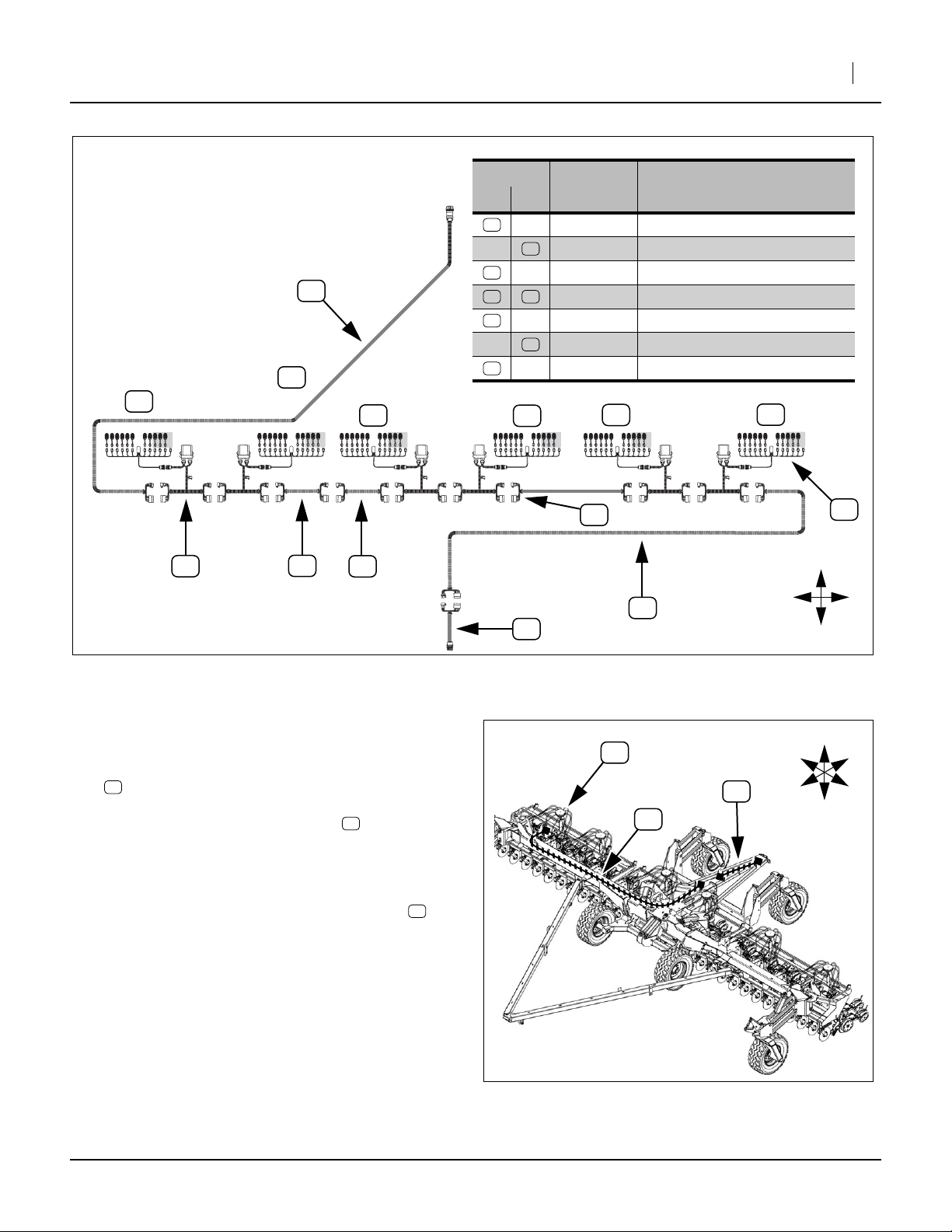
3N-4010HDA Blockage Harness Diagram
92
T2
T1
T3
Callout
New Ex.
31
92
34
35 93
37
94
40
T4
Installation Instructions 9
Harness ID
Part
Number
467751320S1 12 ROW HARNESS
467980130 40’ HITCH HARNESS
467980140 DJ 20’ HARNESS EXT
467980141 10’ EXT HARNESS
467980143 INT AG 25’ HARNESS, WSMB EXT
467980360 3’ REAR HITCH HARNESS
467981201 INT AG HARNESS, WSMB MODULE
T5
Description
T6
40
3N: Install Right-Rear Extension
Refer to Figure 16 and Figure 17
33. Select one new:
37
467980143 INT AG 25’ HARNESS, WSMB EXT
Connect the plug end of extension to the WSMB
harness at Tower 6 (right wing, right end). Route the
harness through the hoop at the right wing pivot.
Route it down the center section to the rear hitch
and connect it to existing rear hitch harness .
Secure with ties.
34. Skip to “Close-Out” on page 29.
35
93
3N-4010HDA Harness Block Diagram
37
94
Figure 16
94
34
T6
37
37
94
31
F
L
R
B
28439
U
R
F
B
L
D
Figure 17
Blockage Harness Route (2 of 2)
10/29/2008 168-414M
28443
Page 10
10 Blockage Monitor Kits
CTA-4000 and 4000HD Installation
This installation requires one of the following kits:
168-408A CTA4000/HD-8006 (80 row, 6in)
168-409A CTA4000/HD-6575 (65 row, 7.5in)
168-410A CTA4000/HD-5010 (50 row, 10in)
Additional installation information is found in the
DICKEY-john IntelliAg Air Cart Control Operator’s manual.
Note: The DICKEY-john manual has only general har-
ness routing for the Great Plains air drills, and
somecable part numbers areslightly differentfrom
those in the kits.
Continuing from step 8 on page 3.
Great Plains Mfg., Inc.
T5
T4
T3
T2
T1
Refer to Figure 18 and Figure 19
9. Select five (5):
12
168-465D DIST TOWER MODULE MOUNT PLATE
At each tower, remove the nuts and lock washers
2 312
at the lower U-Bolt , and mount the plate .
Plate orientation is small holes to top, and:
on Towers 1 & 5: extension to drill center
on Towers 2 & 4: extension to drill rear
on Tower 3: extension to left
1
R
F
CTA: Install WSMBs
Start with the left tower (Tower 1).
10. Select one:
39
467981100S1 INTAG WSMB/FLW MNTR MODULE 18R
and two sets:
14
802-224C HHCS 1/4-20X1 1/4 GR5
16
804-006C WASHER LOCK SPRING 1/4 PLT
15
803-006C NUT HEX 1/4-20 PLT
Mount the WSMB on the tower side of the plate
12
, with the mounting ears flush against the plate
and the connector ports facing down.
11. Repeat step 10 for the remaining towers
39
U
D
3
B
L
Figure 18: CTA:
CTA4000 Tower Arrangement
2
12
17186
1
39
15
16
14
Figure 19: CTA:
Module Mount
168-414M 10/29/2008
27058
Page 11
Great Plains Mfg., Inc.
CTA: Prepare Hoses for Sensors
Refer to Figure 20
DICKEY-john Recon-II blockage sensors require a
hole in the hose for the detectors . The sensor has flex-
1
ible flaps which are tie-wrapped around the seed hose.
The long flap goes over the short flap .
2 3
Note: Usea holesawto makethehole. Use a high speed
drill (to minimize rough edges), and cut slowly (to
minimize risk of drill-through).
30
Installation Instructions 11
2
3
1
Using a drill bit is likely to damage the hose.
Refer to Figure 21 (showing hole on top)
12. Drill one hole in each secondary seed hose at each
tower. Check the first hole for sensor fit before drilling the remaining holes.
The hole location is approximately:
4
13in (33cm)
from where the hose enters the tower.
The hole diameter is:
11
5
3
⁄
to
⁄
16
in (17-19mm)
4
Make the hole on the underside of the hose (toward
center of tower), or rotate the hose to hole-under
after drilling or installing sensor.
CTA: Install Blockage Sensors
Refer to Figure 22 and Figure 20
13. Select one:
30
467420352S1 RECON II
Figure 20: CTA:
Blockage Sensor
30
4
5
Figure 21: CTA:
Sensor Hole Location
30 26 27
28197
28194
2
14. Orient sensor with signal lead toward opener.
Insert the detector head in the hose hole.
Wrap the short flap around the hose.
Wrap the long flap over the short flap.
Check that the long flap overlaps by at least
30
1
3
2
1
⁄
in
4
Opener
Figure 22: CTA:
Mount Sensor
Tower
28195
(6mm), but by no more than 1in (25mm). If the flap
is too long, cut off any excess. Re-check overlap.
15. Select two ties from either:
26
110110050 TY WRAP BUNDLE 50-14"
27
110110099 TY WRAP BUNDLE 100-14"
Secure the sensor to the hose with ties.
10/29/2008 168-414M
Page 12
12 Blockage Monitor Kits
CTA Mount Row Harnesses
Start with Tower 1 (left wing, left tower).
Refer to Figure 23
16. Select one of:
31
467751320S1 12 ROW HARNESS, or
32
467751330S1 16 ROW HARNESS
Observe that the assembly has:
1
one large connector (for the WSMB);
2
a sealed weather-cap module; and,
12 or 16 row sensor connectors, numbered
“ROW 1” through “ROW 12” or “ROW 16“.
Note: There may be more sensor leads than drills rows.
4
“ROW 11” and “ROW 12” are unused on
CTA4000/HD-5010
4
“ROW 14” through “ROW 16” are unused on
CTA4000/HD-6575
All leads are used on CTA4000/HD-8006.
Note: Connector numbering matches harness-to-row
only on Tower 1. At connection step 19, see “Port
Assignment” table on page 33, 34 or 35.
Refer to Figure 24
17. Select one:
13
800-082C CABLE TIE .31X21.5 6DIA 120LB
At the tower, position the weather-cap module :
- lead bundle down,
- just under the upper U-bolt , and;
- on the same side as the WSMB .
3
39
2
1
39
2
345678
2
Figure 23: CTA:
Row Harness
2
Great Plains Mfg., Inc.
4
10 11 12
9
1
31
28198
3
13
Secure the module with tie around the tower
weldment and mounting plate.
18. Repeat step 16 and 17 for Tower 2 through Tower 5.
13
CTA: Sensors to Harnesses
Start with opener 1 (left opener, left wing).
Refer to Figure 25
19. Using the table on pages 33 to 35, determine the
Harness lead (“ROW”) to tower Port assignment.
Isolate each lead from the bundle, and plug the
assigned harness lead and sensor cable together.
20. Select one tie from either:
26
110110050 TY WRAP BUNDLE 50-14"
27
110110099 TY WRAP BUNDLE 100-14"
Tie the harness lead to the same seed hose as its
assigned sensor. Tie about 1in (2.5cm) behind the
cable sheath
21. Repeat step 19 and step 20 for each port on the
tower, and then for each tower. One or four leads
per tower are not connected. Excess cable is tiewrapped at step 23.
26 27
Figure 24: CTA:
Install Row Harness
31
Figure 25: CTA:
Row Harness to Sensor
31
30
28199
28196
168-414M 10/29/2008
Page 13
Great Plains Mfg., Inc.
Installation Instructions 13
CTA: Install WSMB Harnesses
Start with Tower 1 (left wing, left tower)
Refer to Figure 26
22. Select one:
40
467981201 INT AG HARNESS, WSMB MOD-
ULE
Join the row harness connector to the mating
connector on the row harness .
Plug the WSMB connectors into the WSMB .
These connectors are not interchangeable, and are
keyed to ensure correct insertion.
Refer to Figure 24 on page 12
23. Select two:
13
800-082C CABLE TIE .31X21.5 6DIA 120LB
Coil up excess rowharness leads and tie the bundle
to the tower, above and below the lower U-bolt.
24. Repeat step 22 and step 23 for each tower.
1
31
239
CTA: Extend Cart Harness
Refer to Figure 27
25. Locate the existing cart WSMT:
95
467980817S1 WSMTII GP AIR CART MODULE
and the harness connected to it:
96
467980856 GP WSMTII AIR CART HARNESS
31
95
30
U
R
L
D
2
39
5
40
1
3
4
Figure 26: CTA:
WSMB Harness
40
28200
91
96
Figure 27: CTA:
Cart Harness Location
Refer to Figure 28 and Figure 32 on page 15
26. Remove and save the CAN bus terminator:
91
467980126 MINI CAN TERMINATOR
27. At Tower 5, plug the saved CAN bus terminator into
the WSMB harness .
10/29/2008 168-414M
40
96
Figure 28: CTA:
CAN Terminator
96
91
91
28430
28429
Page 14
14 Blockage Monitor Kits
Refer to Figure 29
28. Select one each:
35
467980141 10’ EXT HARNESS
38
467980360 3’ REAR HITCH HARNESS
Interconnect these cables.
Great Plains Mfg., Inc.
95
29. Connect the new cable assembly ( + ) to the
existing cart WSMT harness .
Refer to Figure 30
30. Route the extended cart harness along the right
lower frame tube, up the right rear angled corner
tube, and left across the upper rear tube.
Mount the receptacle end of the harness in the
available large hole at the inside (electrical) bulk-
head at the left rear of the cart.
Secure the harness with ties.
1
35 38
96
R
F
96
U
D
91
B
L
35
38
Figure 29: CTA:
Extend Cart Harness
26400
38
CTA: Complete Drill Harness
Refer to Figure 31 and Figure 32 on page 15
31. Select one new:
33
467980131 20’ HITCH HARNESS
Route the single-connector end from the cart electrical bulkhead . Leave ample slack for hitch
movement.
Follow the left wing hydraulic hoses to the Tower 1
WSMB harness. Leave ample slack near the wing
pivots for folding.
Join the two-connector end to the WSMB harness
40
at Tower 1. Secure hitch harness with ties.
1
R
F
Figure 30: CTA:
Cart Harness Extension Routing
U
B
L
33
D
Figure 31: CTA:
Hitch Harness Routing
35
1
28432
T1
17186
168-414M 10/29/2008
Page 15

Great Plains Mfg., Inc.
CTA Blockage Harness Diagram
Harness ID
Callout
New Ex.
31
32
91
33
35
36
95
96
40
Part
Number
467751320S1 12 ROW HARNESS
467751330S1 16 ROW HARNESS
467980126 MINI CAN TERMINATOR
467980131 20’ HITCH HARNESS
467980141 10’ EXT HARNESS
467980142 5’ EXT HARNESS
467980817S1 WSMTII GP AIR CART MODULE
467980856 GP WSMTII AIR CART HARNESS
467981201 INT AG HARNESS, WSMB MODULE
Description
T1
T2
96
35
T3
33
Installation Instructions 15
L
95
31
32
T4
F
R
B
T5
40
Refer to Figure 32 and Figure 33
32. Select one new:
35
467980141 10’ EXT HARNESS
Connect one end to the WSMB harness at
Tower 1.
Route the harness to Tower 2, following the
large seed inlet hose.
Connect extension to WSMB harness at
Tower 2. Secure extension with ties.
33. Select one new:
36
467980142 5’ EXT HARNESS
Connect one end to the WSMB harness at
Tower 2.
Route the harness to Tower 3, following the
nearest cross-tube.
Connect extension to WSMB harness at
Tower 3. Secure extension with ties.
35
35
36
36
35
CTA-4000/HD Harness Block Diagram
40
40
40
36
Figure 32
40
36
40
35
40
91
28431
T1
T2
35
T3
36
F
L
R
B
Figure 33: CTA:
Tower 1 to Towers 2 and 3
28436
10/29/2008 168-414M
Page 16

16 Blockage Monitor Kits
Refer to Figure 34 and Figure 32 on page 15
34. Select one new:
36
467980142 5’ EXT HARNESS
Connect one end to the WSMB harness at
Tower 3.
Route the harness to Tower 4, following the
nearest cross-tube.
36
40
T3
Great Plains Mfg., Inc.
T5
T4
35
36
Connect extension to WSMB harness at
Tower 4. Secure extension with ties.
35. Select one new:
35
467980141 10’ EXT HARNESS
Connect one end to the WSMB harness at
Tower 4.
Route the harness to Tower 5, following the
large seed inlet hose.
Connect extension to WSMB harness at
Tower 2. Secure extension with ties.
36. Skip to “Close-Out” on page 29.
36
35
35
40
Figure 34: CTA:
Tower 3 to Towers 4 and 5
F
L
R
B
28436
168-414M 10/29/2008
Page 17

Great Plains Mfg., Inc.
NTA-3010 Installation
This installation requires one of the following kits:
168-404A NTA3010-4875 (48 row, 7.5in)
168-405A NTA3010-3610 (36 row,10in)
Additional installation information is found in the
DICKEY-john IntelliAg Air Cart Control Operator’s manual.
Note: The DICKEY-john manual has only general har-
ness routing for the Great Plains air drills, and
somecable part numbers areslightly differentfrom
those in the kits.
Continuing from step 8 on page 3.
Refer to Figure 35 and Figure 36
9. Select four (4):
12
168-465D DIST TOWER MODULE MOUNT PLATE
At each tower, remove the nuts and lock washers
2 312
at the lower U-Bolt , and mount the plate .
1
R
F
U
D
Installation Instructions 17
T4
B
L
Figure 35
NTA3010 Tower Arrangement
T3
T2
T1
28437
Plate orientation is small holes to top, and
extensions to drill center.
NTA30: Install WSMBs
Start with the left tower (Tower 1).
10. Select one:
39
467981100S1 INTAG WSMB/FLW MNTR MODULE 18R
and two sets:
14
802-224C HHCS 1/4-20X1 1/4 GR5
16
804-006C WASHER LOCK SPRING 1/4 PLT
15
803-006C NUT HEX 1/4-20 PLT
Mount the WSMB on the tower side of the plate
12
, with the mounting ears flush against the plate
and the connector ports facing down.
11. Repeat step 10 for the remaining towers
39
1
2
39
12
3
15
16
14
Figure 36: NTA30:
Module Mount
27058
10/29/2008 168-414M
Page 18

18 Blockage Monitor Kits
NTA30: Prepare Hoses for Sensors
Refer to Figure 37
DICKEY-john Recon-II blockage sensors require a
hole in the hose for the detectors . The sensor has flex-
1
ible flaps which are tie-wrapped around the seed hose.
The long flap goes over the short flap .
2 3
Note: Usea holesawto makethehole. Use a high speed
drill (to minimize rough edges), and cut slowly (to
minimize risk of drill-through).
30
Great Plains Mfg., Inc.
2
3
1
Using a drill bit is likely to damage the hose.
Refer to Figure 38 (showing hole on top)
12. Drill one hole in each secondary seed hose at each
tower. Check the first hole for sensor fit before drilling the remaining holes.
The hole location is approximately:
4
13in (33cm)
from where the hose enters the tower.
The hole diameter is:
11
5
3
⁄
to
⁄
16
in (17-19mm)
4
Make the hole on the underside of the hose (toward
center of tower), or rotate the hose to hole-under
after drilling or installing sensor.
NTA30: Install Blockage Sensors
Refer to Figure 39 and Figure 37
13. Select one:
30
467420352S1 RECON II
Figure 37: NTA30:
Blockage Sensor
30
4
5
Figure 38: NTA30:
Sensor Hole Location
30 26 27
28197
28194
2
14. Orient sensor with signal lead toward opener.
Insert the detector head in the hose hole.
Wrap the short flap around the hose.
Wrap the long flap over the short flap.
Check that the long flap overlaps by at least
30
1
3
2
1
⁄
in
4
Opener
Figure 39: NTA30:
Mount Sensor
Tower
28195
(6mm), but by no more than 1in (25mm). If the flap
is too long, cut off any excess. Re-check overlap.
15. Select two ties from either:
26
110110050 TY WRAP BUNDLE 50-14"
27
110110099 TY WRAP BUNDLE 100-14"
Secure the sensor to the hose with ties.
168-414M 10/29/2008
Page 19

Great Plains Mfg., Inc.
NTA30 Mount Row Harnesses
Start with Tower 1 (left wing, left tower).
Refer to Figure 40
16. Select one of:
31
467751320S1 12 ROW HARNESS, or
32
467751330S1 16 ROW HARNESS
Observe that the assembly has:
1
one large connector (for the WSMB);
2
a sealed weather-cap module; and,
12 or 16 row sensor connectors, numbered
“ROW 1” through “ROW 12”.
Note: There may be more sensor leads than drills rows.
4
“ROW 10” through “ROW 12” are unused on
NTA3010-3610
All leads are used on NTA3010-4875.
Note: Connector numbering matches harness-to-row
only on Tower 1. At connection step 19, see “Port
Assignment” table on page 36 or 37.
Refer to Figure 41
17. Select one:
13
800-082C CABLE TIE .31X21.5 6DIA 120LB
At the tower, position the weather-cap module :
- lead bundle down,
- just under the upper U-bolt , and;
- on the same side as the WSMB .
3
39
2
39
Installation Instructions 19
4
2
1
345678
2
10 11 12
9
1
Figure 40: NTA30:
Row Harness or
31
32
28198
2
3
13
Secure the module with tie around the tower
weldment and mounting plate.
18. Repeat step 16 and step 17 for Tower 2 through
Tower 4.
13
NTA30: Sensors to Harnesses
Start with opener 1 (left opener, left wing).
Refer to Figure 42
19. Using the table on pages 36 or 37, determine the
Harness lead (“ROW”) to tower Port assignment.
Isolate each lead from the bundle, and plug the
assigned harness lead and sensor cable together.
20. Select one tie from either:
26
110110050 TY WRAP BUNDLE 50-14"
27
110110099 TY WRAP BUNDLE 100-14"
Tie the harness lead to the same seed hose as its
assigned sensor. Tie about 1in (2.5cm) behind the
cable sheath
21. Repeat step 19 and step 20 for each port on the
tower, and then for each tower. One or four leads
per tower are not connected. Excess cable is tiewrapped at step 23.
26 27
Figure 41: NTA30:
Install Row Harness
31
Figure 42: NTA30:
Row Harness to Sensor
31
30
28199
28196
10/29/2008 168-414M
Page 20

20 Blockage Monitor Kits
Great Plains Mfg., Inc.
NTA30: Install WSMB Harnesses
Start with Tower 1 (left wing, left tower)
Refer to Figure 43
22. Select one:
40
467981201 INT AG HARNESS, WSMB MODULE
Join the row harness connector to the mating
connector on the row harness .
Plug the WSMB connectors into the WSMB .
These connectors are not interchangeable, and are
keyed to ensure correct insertion.
Refer to Figure 41 on page 19
23. Select two:
13
800-082C CABLE TIE .31X21.5 6DIA 120LB
Coil up excess rowharness leads and tie the bundle
to the tower, above and below the lower U-bolt.
24. Repeat step 22 and step 23 for each tower.
Refer to Figure 44, 45 and Figure 46 on page 21
25. Select one new:
34
467980140 DJ 20’ HARNESS EXT
26. At the front center of the drill, locate the existing
implement WSMB:
97
467982000S1 PLNTR CNTRL OUTPUT MODULE(POM)
1
31
239
31
30
U
R
L
D
2
39
5
40
1
3
4
Figure 43: NTA30:
WSMB Harness
40
28200
97
At the WSMB connectors, follow harness:
98
467983502 DJ 2SOL YP24LIFT/HITCH FCM HRN
Locate the CAN bus terminator:
91
467980126 MINI CAN TERMINATOR
27. Remove and save the terminator .
Connect the 20ft harness extension in its place
(two connectors).
Refer to Figure 45 and Figure 46 on page 21
28. At Tower 4, plug the saved CAN bus terminator
into the WSMB harness .
40
91
34
91
98
98
Figure 44: NTA30:
Existing WSMB Location
97
91
Figure 45: NTA30:
CAN Terminator
98
28438
28429
168-414M 10/29/2008
Page 21

Great Plains Mfg., Inc.
NTA30 Blockage Harness Diagram
Harness ID
Callout
New Ex.
31
91
34
35
36
40
97
98
Part
Number
467751320S1 12 ROW HARNESS
467980126 MINI CAN TERMINATOR
467980140 DJ 20’ HARNESS EXT
467980141 10’ EXT HARNESS
467980142 5’ EXT HARNESS
467981201 INT AG HARNESS, WSMB MODULE
467982000S1
467983502
PLNTR CNTRL OUTPUT MODULE(POM)
DJ 2SOL YP24LIFT/HITCH FCM HRN
Description
98
97
Installation Instructions 21
F
L
R
B
31
T1
34
40
Refer to Figure 46 and Figure 47
29. Following the large inlet seed tube to Tower 1, route
20ft extension harness to the WSMB at Tower
one. Connect it to the WSMB harness . Do not
secure harness with ties until the next step.
34
35
NTA-3010 Harness Block Diagram
40
40
Figure 46
T2
36
T3
T4
91
40
35
40
28440
F
97
L
R
B
34
T2
T1
Figure 47: NTA30:
Implement WSMB to Tower 1
10/29/2008 168-414M
16899
Page 22

22 Blockage Monitor Kits
Great Plains Mfg., Inc.
Refer to Figure 48 and Figure 46 on page 21
30. Select one new:
35
467980141 10’ EXT HARNESS
Following the Tower 1 inlet seed tube again, route
this extension between the WSMB harness at
Tower 1 and the WSMB harness at Tower 2. Connect both ends of the extension.
Allowing slack for wing folding, secure harnesses
34 35
and with cable ties.
Refer to Figure 49 and Figure 46 on page 21
31. Select one new:
36
467980142 5’ EXT HARNESS
Route this extension between the WSMB harness
at Tower 2 and the WSMB harness at Tower 3. Connect both ends of the extension.
Secure harness to the cross-tube with cable ties.
36
F
L
R
B
35
T2
T1
Figure 48: NTA30:
Tower 1 to Tower 2
16899
F
L
R
B
36
Refer to Figure 50 and Figure 46 on page 21
32. Select one new:
35
467980141 10’ EXT HARNESS
Following the inlet seed hose for Tower 4, route this
extension between the WSMB harness at Tower 3
and the WSMB harness at Tower 4. Connect both
ends of the extension.
Allowing slack for wing folding, secure harness
with cable ties.
33. Skip to “Close-Out” on page 29.
35
T3
T2
Figure 49: NTA30:
Tower 2 to Tower 3
35
Figure 50: NTA30:
Tower 3 to Tower 4
T3
16899
F
L
R
B
T4
16899
168-414M 10/29/2008
Page 23

Great Plains Mfg., Inc.
NTA-3510 Installation
This installation requires one of the following kits:
168-406A NTA3510-5575 (55 row, 7.5in)
168-407A NTA3510-4010 (40 row,10in)
Additional installation information is found in the
DICKEY-john IntelliAg Air Cart Control Operator’s manual.
Note: The DICKEY-john manual has only general har-
ness routing for the Great Plains air drills, and
somecable part numbers areslightly differentfrom
those in the kits.
Continuing from step 8 on page 3.
Refer to Figure 51 and Figure 52
9. Select five (5):
12
168-465D DIST TOWER MODULE MOUNT PLATE
At each tower, remove the nuts and lock washers
2 312
at the lower U-Bolt , and mount the plate .
1
R
F
U
D
Installation Instructions 23
T5
B
L
Figure 51
NTA 3510 Tower Arrangement
T4
T3
T2
T1
29020
Plate orientation is small holes to top, and
T1 T5
, : plate to drill center,
T2 T4
, : plate to drill center,
T3
: plate to drill rear.
NTA35: Install WSMBs
Start with the left tower (Tower 1).
10. Select one:
39
467981100S1 INTAG WSMB/FLW MNTR MODULE 18R
and two sets:
14
802-224C HHCS 1/4-20X1 1/4 GR5
16
804-006C WASHER LOCK SPRING 1/4 PLT
15
803-006C NUT HEX 1/4-20 PLT
Mount the WSMB on the tower side of the plate
12
, with the mounting ears flush against the plate
and the connector ports facing down.
11. Repeat step 10 for the remaining towers
39
1
2
39
12
3
15
16
14
Figure 52: NTA35:
Module Mount
27058
10/29/2008 168-414M
Page 24

24 Blockage Monitor Kits
NTA35: Prepare Hoses for Sensors
Refer to Figure 53
DICKEY-john Recon-II blockage sensors require a
hole in the hose for the detectors . The sensor has flex-
1
ible flaps which are tie-wrapped around the seed hose.
The long flap goes over the short flap .
2 3
Note: Usea holesawto makethehole. Use a high speed
drill (to minimize rough edges), and cut slowly (to
minimize risk of drill-through).
30
Great Plains Mfg., Inc.
2
3
1
Using a drill bit is likely to damage the hose.
Refer to Figure 54 (showing hole on top)
12. Drill one hole in each secondary seed hose at each
tower. Check the first hole for sensor fit before drilling the remaining holes.
The hole location is approximately:
4
13in (33cm)
from where the hose enters the tower.
The hole diameter is:
11
5
3
⁄
to
⁄
16
in (17-19mm)
4
Make the hole on the underside of the hose (toward
center of tower), or rotate the hose to hole-under
after drilling or installing sensor.
NTA35: Install Blockage Sensors
Refer to Figure 55 and Figure 53
13. Select one:
30
467420352S1 RECON II
Figure 53: NTA35:
Blockage Sensor
30
4
5
Figure 54: NTA35:
Sensor Hole Location
30 26 27
28197
28194
2
14. Orient sensor with signal lead toward opener.
Insert the detector head in the hose hole.
Wrap the short flap around the hose.
Wrap the long flap over the short flap.
Check that the long flap overlaps by at least
30
1
3
2
1
⁄
in
4
Opener
Figure 55: NTA35:
Mount Sensor
Tower
28195
(6mm), but by no more than 1in (25mm). If the flap
is too long, cut off any excess. Re-check overlap.
15. Select two ties from either:
26
110110050 TY WRAP BUNDLE 50-14"
27
110110099 TY WRAP BUNDLE 100-14"
Secure the sensor to the hose with ties.
168-414M 10/29/2008
Page 25

Great Plains Mfg., Inc.
NTA35 Mount Row Harnesses
Start with Tower 1 (left wing, left tower).
Refer to Figure 56
16. Select one new:
31
467751320S1 12 ROW HARNESS
Observe that the assembly has:
1
one large connector (for the WSMB);
2
a sealed weather-cap module; and,
12 or 16 row sensor connectors, numbered
“ROW 1” through “ROW 12”.
Note: There may be more sensor leads than drills rows.
4
“ROW 9” through “ROW 12” are unused on
NTA3510-4010
All leads are used on NTA3510-5575.
Note: Connector numbering matches harness-to-row
only on Tower 1. At connection step 19, see “Port
Assignment” table on page 36 or 37.
Refer to Figure 57
17. Select one:
13
800-082C CABLE TIE .31X21.5 6DIA 120LB
At the tower, position the weather-cap module :
- lead bundle down,
- just under the upper U-bolt , and;
- on the same side as the WSMB .
3
39
2
Installation Instructions 25
4
2
1
345678
2
10 11 12
9
1
Figure 56: NTA35:
Row Harness
31
28198
2
3
39
13
Secure the module with tie around the tower
weldment and mounting plate.
18. Repeat step 16 and step 17 for Tower 2 through
Tower 5.
13
NTA35: Sensors to Harnesses
Start with opener 1 (left opener, left wing).
Refer to Figure 58
19. Using the table on pages 38 or 39, determine the
Harness lead (“ROW”) to tower Port assignment.
Isolate each lead from the bundle, and plug the
assigned harness lead and sensor cable together.
20. Select one tie from either:
26
110110050 TY WRAP BUNDLE 50-14"
27
110110099 TY WRAP BUNDLE 100-14"
Tie the harness lead to the same seed hose as its
assigned sensor. Tie about 1in (2.5cm) behind the
cable sheath
21. Repeat step 19 and step 20 for each port on the
tower, and then for each tower. One or four leads
per tower are not connected. Excess cable is tiewrapped at step 23.
26 27
Figure 57: NTA35:
Install Row Harness
31
Figure 58: NTA35:
Row Harness to Sensor
31
30
28199
28196
10/29/2008 168-414M
Page 26

26 Blockage Monitor Kits
Great Plains Mfg., Inc.
NTA35: Install WSMB Harnesses
Start with Tower 1 (left wing, left tower)
Refer to Figure 59
22. Select one:
40
467981201 INT AG HARNESS, WSMB MODULE
Join the row harness connector to the mating
connector on the row harness .
Plug the WSMB connectors into the WSMB .
These connectors are not interchangeable, and are
keyed to ensure correct insertion.
Refer to Figure 57 on page 25
23. Select two:
13
800-082C CABLE TIE .31X21.5 6DIA 120LB
Coil up excess rowharness leads and tie the bundle
to the tower, above and below the lower U-bolt.
24. Repeat step 22 and step 23 for each tower.
1
31
239
NTA35: Interconnect Center WSMBs
The center section Towers 2, 3 and 4 are close enough
that their WSMB harnesses are directly interconnected.
Refer to Figure 60
25. At the center section WSMB harnesses for
Tower 2 and Tower 3, interconnect
3
the female (receptacle) of left (outer) CAN bus
with
5
the male (plug) end of the mid-wing CAN bus.
Also connect the
4
power receptacle and plug
Note: The unconnected Tower 3 CAN bus connector (at
drill center) must be a receptacle.
26. Interconnect the WSMB harnesses for Tower 3
and Tower 4.
Refer to Figure 61, and Figure 62 and 63 on page 27
27. Select one new:
34
467980140 DJ 20’ HARNESS EXT
28. At the front center of the drill, locate the existing
implement WSMB:
97
467982000S1 PLNTR CNTRL OUTPUT MODULE(POM)
40
40
31
5
39
1
3
4
Figure 59: NTA35:
WSMB Harness
U
L
3
D
40
4
Figure 60: NTA35:
Center Towers Interconnect
30
U
R
L
D
2
5
40
28200
40
R
5
3
40
28201
97
At the WSMB connectors, follow harness:
98
467983502 DJ 2SOL YP24LIFT/HITCH FCM HRN
Locate the CAN bus terminator:
91
467980126 MINI CAN TERMINATOR
168-414M 10/29/2008
Figure 61: NTA35:
Existing WSMB Location
98
28438
97
Page 27

Great Plains Mfg., Inc.
Installation Instructions 27
29. Remove and save the terminator .
Connect the 20ft harness extension in its place
(two connectors).
Refer to Figure 62 and Figure 63
30. At Tower 5, plug the saved CAN bus terminator
into the WSMB harness .
40
91
34
NTA35 Blockage Harness Diagram
Harness ID
Callout
New Ex.
31
91
34
35
40
97
98
Part
Number
467751320S1 12 ROW HARNESS
467980126 MINI CAN TERMINATOR
467980140 DJ 20’ HARNESS EXT
467980141 10’ EXT HARNESS
467981201 INT AG HARNESS, WSMB MODULE
467982000S1
467983502
PLNTR CNTRL OUTPUT MODULE(POM)
DJ 2SOL YP24LIFT/HITCH FCM HRN
Description
91
98
98
97
91
Figure 62: NTA35:
CAN Terminator
98
28429
F
L
R
B
34
40
T1
T3
T2
35
NTA-3510 Harness Block Diagram
40
40
Figure 63
40
T4
35
31
T5
91
40
28441
10/29/2008 168-414M
Page 28

28 Blockage Monitor Kits
Great Plains Mfg., Inc.
Refer to Figure 63 on page 27 and Figure 64
31. Following the large inlet seed tube to Tower 1, route
20ft extension harness to the WSMB at Tower
one. Connect it to the WSMB harness . Do not
secure harness with ties until the next step.
Refer to Figure 65 and Figure 63 on page 27
32. Select one new:
35
467980141 10’ EXT HARNESS
Following the Tower 1 inlet seed tube again, route
this extension between the WSMB harness at
Tower 1 and the WSMB harness at Tower 2. Connect both ends of the extension.
34
40
L
L
T1
F
B
F
B
R
34
Figure 64: NTA35:
Implement WSMB to Tower 1
R
35
97
T3
T2
16201
Allowing slack for wing folding, secure harnesses
34 35
and with cable ties.
Refer to Figure 66 and Figure 63 on page 27
33. Select one new:
35
467980141 10’ EXT HARNESS
Following the inlet seed hose for Tower 5, route this
extension between the WSMB harness at Tower 4
and the WSMB harness at Tower 5. Connect both
ends of the extension.
Allowing slack for wing folding, secure harness
with cable ties.
34. Skip to “Close-Out” on page 29.
35
T1
T3
T4
Figure 65: NTA35:
Tower 1 to Tower 2
35
Figure 66: NTA35:
Tower 4 to Tower 5
L
T2
T3
16201
F
R
B
T5
16201
168-414M 10/29/2008
Page 29

Great Plains Mfg., Inc.
Close-Out
Refer to Figure 67
37. Select all of:
29
464211090 DUST PLUG
Insert these at all unused row sensor leads on row
harnesses.
38. Select all remaining cable ties. Use them to further
secure all harnesses.
Check Operation
39. Hitch to suitable tractor.
40. Power-up seed monitor. Consult DICKEY-john Air
Cart Control operator manual and run Auto Configuration.
41. Fold, unfold,raise and lower drill while checkingthat
hoses and sensor lines remain clear of moving
parts and retain some slack at all times.
42. Fold the drill. Move it to a suitable parking location.
Installation Instructions 29
29
Figure 67
Dust Plugs
29
28442
10/29/2008 168-414M
Page 30

30 Blockage Monitor Kits
Appendix
Torque Chart
Great Plains Mfg., Inc.
Bolt
Size
in-tpi
1
1
5
⁄16-18
5
⁄16-24
3
3
7
⁄16-14
7
⁄16-20
1
1
9
⁄16-12
9
⁄16-18
5
5
3
3
7
7
1-12
11⁄8-7
11⁄8-12
11⁄4-7
11⁄4-12
13⁄8-6
13⁄8-12
11⁄2-6
11⁄2-12
25199
Bolt Head Identification
Bolt Head Identification
Bolt
Size
Grade 2 Grade 5 Grade 8 Class 5.8 Class 8.8 Class 10.9
1
N-m2ft-lb
⁄4-20
⁄4-28
⁄8-16
⁄8-24
⁄2-13
⁄2-20
⁄8-11
⁄8-18
⁄4-10
⁄4-16
⁄8-9
⁄8-14
1-8
7.4 5.6 11 8 16 12
8.5 6 13 10 18 14
15 11 24 17 33 25
17 13 26 19 37 27
27 20 42 31 59 44
31 22 47 35 67 49
43 32 67 49 95 70
49 36 75 55 105 78
66 49 105 76 145 105
75 55 115 85 165 120
95 70 150 110 210 155
105 79 165 120 235 170
130 97 205 150 285 210
150 110 230 170 325 240
235 170 360 265 510 375
260 190 405 295 570 420
225 165 585 430 820 605
250 185 640 475 905 670
340 250 875 645 1230 910
370 275 955 705 1350 995
480 355 1080 795 1750 1290
540 395 1210 890 1960 1440
680 500 1520 1120 2460 1820
750 555 1680 1240 2730 2010
890 655 1990 1470 3230 2380
1010 745 2270 1670 3680 2710
1180 870 2640 1950 4290 3160
1330 980 2970 2190 4820 3560
Torque tolerance + 0%, -15% of torquing values. Unless otherwise specified use torque values listed above.
3
N-m ft-lb N-m ft-lb
mm x pitch
M 5 X 0.8
M 6 X 1
M 8 X 1.25
M 8 X 1
M10 X 1.5
M10 X 0.75
M12 X 1.75
M12 X 1.5
M12 X 1
M14 X 2
M14 X 1.5
M16 X 2
M16 X 1.5
M18 X 2.5
M18 X 1.5
M20 X 2.5
M20 X 1.5
M24 X 3
M24 X 2
M30 X 3.5
M30 X 2
M36 X 3.5
M36 X 2
1. in-tpi = nominal thread diameter in inches-threads per inch
2. N· m = newton-meters
3. ft-lb = foot pounds
4. mm x pitch = nominal thread diameter in millimeters x thread
pitch
4
5.8 8.8 10.9
N-m ft-lb N-m ft-lb N-m ft-lb
43659 7
7 5 11 8 15 11
17 12 26 19 36 27
18 13 28 21 39 29
33 24 52 39 72 53
39 29 61 45 85 62
58 42 91 67 125 93
60 44 95 70 130 97
90 66 105 77 145 105
92 68 145 105 200 150
99 73 155 115 215 160
145 105 225 165 315 230
155 115 240 180 335 245
195 145 310 230 405 300
220 165 350 260 485 355
280 205 440 325 610 450
310 230 650 480 900 665
480 355 760 560 1050 780
525 390 830 610 1150 845
960 705 1510 1120 2100 1550
1060 785 1680 1240 2320 1710
1730 1270 2650 1950 3660 2700
1880 1380 2960 2190 4100 3220
168-414M 10/29/2008
Page 31

Great Plains Mfg., Inc.
Installation Instructions 31
3N4010HDA Port Assignments, 10in (25.4cm) Drill
Drill Model: 3N-4010HDA-4810
Towers are numbered from drill left (Tower 1).
Harness connectors are numbered on the cable:“Row 1”
through “Row 12” (some are not connected [n/c]).
Tower Harness Port Opener Tower Harness Port Opener
ROW 3 Port 1 3
ROW 1 Port 2 1 ROW 4 Port 2 28
ROW 2 Port 3 2 ROW 6 Port 3 30
ROW 4 Port 4 4 ROW 8 Port 4 32
Tower 1
Tower 2
Tower 3
ROW 6 Port 5 6 ROW 7 Port 5 31
ROW 8 Port 6 8 ROW 5 Port 6 29
ROW 7 Port 7 7 ROW 3 Port 7 27
ROW 5 Port 8 5 ROW 1 Port 8 25
ROW 9-12 n/c - ROW 9-12 n/c -
ROW 3 Port 1 11
ROW 1 Port 2 9 ROW 3 Port 2 35
ROW 2 Port 3 10 ROW 1 Port 3 33
ROW 4 Port 4 12 ROW 2 Port 4 34
ROW 6 Port 5 14 ROW 4 Port 5 36
ROW 8 Port 6 16 ROW 6 Port 6 38
ROW 7 Port 7 15 ROW 8 Port 7 40
ROW 5 Port 8 13 ROW 7 Port 8 39
ROW 9-12 n/c - ROW 9-12 n/c -
ROW 7 Port 1 23
ROW 5 Port 2 21 ROW 1 Port 2 41
ROW 3 Port 3 19 ROW 2 Port 3 42
ROW 1 Port 4 17 ROW 4 Port 4 44
ROW 2 Port 5 18 ROW 6 Port 5 46
ROW 4 Port 6 20 ROW 8 Port 6 48
ROW 6 Port 7 22 ROW 7 Port 7 47
ROW 8 Port 8 24 ROW 5 Port 8 45
ROW 9-12 n/c ROW 9-12 n/c
Tower Ports are numbered Clockwise from mount center
(Port 1) to Port 8.
Openers are numbered from drill left (Row 1).
ROW 2 Port 1 26
Tower 4
ROW 5 Port 1 37
Tower 5
ROW 3 Port 1 43
Tower 6
10/29/2008 168-414M
Page 32

Great Plains Mfg., Inc.
32 Blockage Monitor Kits
3N4010HDA Port Assignments, 7.5in (19.2cm) Drill
Drill Model: 3N-4010HDA-6675
Towers are numbered from drill left (Tower 1).
Harness connectors are numbered on the cable: “ROW
1” through “ROW 12” (some are not connected [n/c]).
Tower Harness Port Opener Tower Harness Port Opener
ROW 6 Port 1 6
ROW 4 Port 2 4 ROW 4 Port 2 37
ROW 2 Port 3 2 ROW 6 Port 3 39
ROW 1 Port 4 1 ROW 8 Port 4 41
ROW 3 Port 5 3 ROW 10 P ort 5 43
Tower 1
Tower 2
Tower 3
ROW 5 Port 6 5 ROW 11 P ort 6 44
ROW 7 Port 7 7 ROW 9 Port 7 42
ROW 9 Port 8 9 ROW 7 Port 8 40
ROW 11 Port 9 11 ROW 5 Port 9 38
ROW 10 Port 10 10 ROW 3 Port 10 36
ROW 8 Port 11 8 ROW 1 Port 11 34
ROW 12 n/c - ROW 12 n/c -
ROW 5 Port 1 16
ROW 3 Port 2 14 ROW 4 Port 2 48
ROW 1 Port 3 12 ROW 2 Port 3 46
ROW 2 Port 4 13 ROW 1 Port 4 45
ROW 4 Port 5 15 ROW 3 Port 5 47
ROW 6 Port 6 17 ROW 5 Port 6 49
ROW 8 Port 7 19 ROW 7 Port 7 51
ROW 10 Port 8 21 ROW 9 Port 8 53
ROW 11 Port 9 22 ROW 11 Port 9 55
ROW 9 Port 10 20 ROW 10 Port 10 54
ROW 7 Port 11 18 ROW 8 Port 11 52
ROW 12 n/c - ROW 12 n/c ROW 11 Port 1 33
ROW 10 Port 2 32 ROW 3 Port 2 58
ROW 8 Port 3 30 ROW 1 Port 3 56
ROW 6 Port 4 28 ROW 2 Port 4 57
ROW 4 Port 5 26 ROW 4 Port 5 59
ROW 2 Port 6 24 ROW 6 Port 6 61
ROW 1 Port 7 23 ROW 8 Port 7 63
ROW 3 Port 8 25 ROW 10 Port 8 65
ROW 5 Port 9 27 ROW 11 Port 9 66
ROW 7 Port 10 29 ROW9 Port 10 64
ROW 9 Port 11 31 ROW7 Port 11 62
ROW 12 n/c - ROW 12 n/c -
Ports are numbered Clockwise from mount center (Port
1) to Port 11.
Openers are numbered from drill left (Row 1).
ROW 2 Port 1 35
Tower 4
ROW 6 Port 1 50
Tower 5
ROW 5 Port 1 60
Tower 6
168-414M 10/29/2008
Page 33

Great Plains Mfg., Inc.
Installation Instructions 33
CTA4000/HD Port Assignments, 10in (25.4cm) Drill
Drill Model: CTA4000-5010, CTA4000HD-5010
Towers are numbered from drill left (Tower 1).
Harness connectors are numbered on the cable:“Row 1”
through “Row 12” (some are not connected [n/c]).
Tower Harness Port Opener Tower Harness Port Opener
ROW 7 Port 1 7
ROW 9 Port 2 9 ROW 2 Port 2 32
ROW10 Port3 10 ROW5 Port3 35
ROW 8 Port 4 8 ROW 7 Port 4 37
ROW 6 Port 5 6 ROW 9 Port 5 39
Tower 1
Tower 2
Tower 3
ROW4 Port6 4 ROW10 Port6 40
ROW 2 Port 7 2 ROW 8 Port 7 38
ROW 1 Port 8 1 ROW 6 Port 8 36
ROW 3 Port 9 3 ROW 4 Port 9 34
ROW 5 Port 10 5 ROW 2 Port 10 32
ROW 11-12 n/c - ROW 11-12 n/c -
ROW 10 Port 1 20
ROW 8 Port 2 18 ROW 7 Port 2 47
ROW 6 Port 3 16 ROW 9 Port 3 49
ROW 4 Port 4 14 ROW 10 Port 4 50
ROW 2 Port 5 12 ROW 8 Port 5 48
ROW 1 Port 6 11 ROW 6 Port 6 46
ROW 3 Port 7 13 ROW 4 Port 7 44
ROW 5 Port 8 15 ROW 2 Port 8 42
ROW 7 Port 9 17 ROW 1 Port 9 41
ROW 9 Port 10 19 ROW 3 Port 10 43
ROW 11-12 n/c - ROW 11-12 n/c -
ROW 4 Port 1 24
ROW 2 Port 2 22
ROW 1 Port 3 21
ROW 3 Port 4 23
ROW 5 Port 5 25
ROW 7 Port 6 27
ROW 9 Port 7 29
ROW10 Port8 30
ROW 8 Port 9 28
ROW 6 Port 10 26
ROW 11-12 n/c -
Tower Ports are numbered Clockwise from mount center
(Port 1) to Port 10.
Openers are numbered from drill left (Row 1).
ROW 1 Port 1 31
Tower 4
ROW 5 Port 1 45
Tower 5
10/29/2008 168-414M
Page 34

Great Plains Mfg., Inc.
34 Blockage Monitor Kits
CTA4000/HD Port Assignments, 7.5in (19.2cm) Drill
Drill Model: CTA4000-6575, CTA4000HD-6575
Towers are numbered from drill left (Tower 1).
Harness connectors are numbered on the cable: “ROW
1” through “ROW 16” (some are not connected [n/c]).
Tower Harness Port Opener Tower Harness Port Opener
ROW 8 Port 1 8
ROW10 Port2 10 ROW4 Port2 43
ROW13 Port3 13 ROW6 Port3 45
ROW12 Port4 12 ROW8 Port4 47
ROW11 Port5 11 ROW10 Port5 49
ROW9 Port6 9 ROW12 Port6 51
Tower 1
Tower 2
Tower 3
ROW7 Port7 7 ROW13 Port7 52
ROW6 Port8 6 ROW11 Port8 50
ROW 5 Port 9 5 ROW 9 Port 9 48
ROW 2 Port 10 2 ROW 7 Port 10 46
ROW 1 Port 11 1 ROW 5 Port 11 44
ROW 3 Port 12 3 ROW 3 Port 12 42
ROW 4 Port 13 4 ROW 1 Port 13 40
ROW 14-16 n/c - ROW 14-16 n/c -
ROW 13 Port 1 26
ROW 11 Port 2 24 ROW 7 Port 2 59
ROW 9 Port 3 22 ROW 9 Port 3 61
ROW 7 Port 4 20 ROW 11 Port 4 63
ROW 5 Port 5 18 ROW 13 Port 5 65
ROW 3 Port 6 16 ROW 12 Port 6 64
ROW 1 Port 7 14 ROW 10 Port 7 62
ROW 2 Port 8 15 ROW 8 Port 8 60
ROW 4 Port 9 17 ROW 6 Port 9 58
ROW 6 Port 10 19 ROW 4 Port 10 56
ROW 8 Port 11 21 ROW 2 Port 11 54
ROW 10 Port 12 23 ROW 1 Port 12 53
ROW 12 Port 13 25 ROW 3 Port 13 55
ROW 14-16 n/c - ROW 14-16 n/c -
ROW 8 Port 1 34
ROW 6 Port 2 32
ROW 4 Port 3 30
ROW 2 Port 4 28
ROW 1 Port 5 27
ROW 3 Port 6 29
ROW 5 Port 7 31
ROW 7 Port 8 33
ROW 9 Port 9 35
ROW11 Port10 37
ROW13 Port11 39
ROW12 Port12 38
ROW10 Port13 36
ROW 14-16 n/c -
Ports are numbered Clockwise from mount center (Port
1) to Port 13.
Openers are numbered from drill left (Row 1).
ROW 2 Port 1 41
Tower 4
ROW 5 Port 1 57
Tower 5
168-414M 10/29/2008
Page 35

Great Plains Mfg., Inc.
Installation Instructions 35
CTA4000/HD Port Assignments, 6in (15.2cm) Drill
Drill Model: CTA4000-8006, CTA4000HD-8006
Towers are numbered from drill left (Tower 1).
Harness connectors are numbered on the cable: “ROW
1” through “ROW 16”
Tower Harness Port Opener Tower Harness Port Opener
ROW 13 Port 1 13
ROW 14 Port 2 14 ROW 5 Port 2 53
ROW 15 Port 3 15 ROW 6 Port 3 54
ROW 16 Port 4 16 ROW 7 Port 4 55
ROW 12 Port 5 12 ROW 11 Port 5 59
ROW 10 Port 6 10 ROW 12 Port 6 60
ROW 8 Port 7 8 ROW 13 Port 7 61
Tower 1
Tower 2
Tower 3
ROW 6 Port 8 6 ROW 15 Port 8 63
ROW 4 Port 9 4 ROW 16 Port 9 64
ROW 2 Port 10 2 ROW 14 Port 10 62
ROW 1 Port 11 1 ROW 10 Port 11 58
ROW 3 Port 12 3 ROW 9 Port 12 57
ROW 5 Port 13 5 ROW 8 Port 13 56
ROW 7 Port 14 7 ROW 4 Port 14 52
ROW 9 Port 15 9 ROW 3 Port 15 51
ROW 11 Port 16 11 ROW 1 Port 16 49
ROW 14 Port 1 30
ROW 12 Port 2 28 ROW 7 Port 2 71
ROW 10 Port 3 26 ROW 11 Port 3 75
ROW 16 Port 4 32 ROW 13 Port 4 77
ROW 6 Port 5 22 ROW 15 Port 5 79
ROW 4 Port 6 20 ROW 16 Port 6 80
ROW 2 Port 7 18 ROW 14 Port 7 78
ROW 1 Port 8 17 ROW 12 Port 8 76
ROW 3 Port 9 19 ROW 10 Port 9 74
ROW 5 Port 10 21 ROW 9 Port 10 73
ROW 7 Port 11 23 ROW 8 Port 11 72
ROW 8 Port 12 24 ROW 6 Port 12 70
ROW 9 Port 13 25 ROW 4 Port 13 68
ROW 11 Port 14 27 ROW 2 Port 14 66
ROW 13 Port 15 29 ROW 1 Port 15 65
ROW 15 Port 16 31 ROW 3 Port 16 67
ROW 7 Port 1 39
ROW 6 Port 2 38
ROW 3 Port 3 35
ROW 4 Port 4 36
ROW 5 Port 5 37
ROW 1 Port 6 33
ROW 2 Port 7 34
ROW 8 Port 8 40
ROW 9 Port 9 41
ROW 10 Port 10 42
ROW 11 Port 11 43
ROW 14 Port 12 46
ROW 16 Port 13 48
ROW 15 Port 14 47
ROW 13 Port 15 45
ROW 12 Port 16 44
Ports are numbered Clockwise from mount center (Port
1) to Port 11.
Openers are numbered from drill left (Row 1).
ROW 2 Port 1 50
Tower 4
ROW 5 Port 1 69
Tower 5
10/29/2008 168-414M
Page 36

Great Plains Mfg., Inc.
36 Blockage Monitor Kits
NTA-3010 Port Assignments, 10in (25.4cm) Drill
Drill Model: NTA3010-3610
Towers are numbered from drill left (Tower 1).
Harness connectors are numbered on the cable:“Row 1”
through “Row 12” (some are not connected [n/c]).
Tower Harness Port Opener Tower Harness Port Opener
ROW 5 Port 1 5
ROW 3 Port 2 3 ROW 3 Port 2 21
ROW 1 Port 3 1 ROW 1 Port 3 19
ROW 2 Port 4 2 ROW 2 Port 4 20
Tower 1
Tower 2
ROW 4 Port 5 4 ROW 4 Port 5 22
ROW 6 Port 6 6 ROW 6 Port 6 24
ROW 8 Port 7 8 ROW 7 Port 7 25
ROW 9 Port 8 9 ROW 9 Port 8 27
ROW 7 Port 9 7 ROW 8 Port 9 26
ROW 10-12 n/c - ROW 10-12 n/c -
ROW 5 Port 1 14
ROW 4 Port 2 13 ROW 4 Port 2 31
ROW 2 Port 3 11 ROW 2 Port 3 29
ROW 1 Port 4 10 ROW 1 Port 4 28
ROW 3 Port 5 12 ROW 3 Port 5 30
ROW 6 Port 6 15 ROW 5 Port 6 32
ROW 7 Port 7 16 ROW 7 Port 7 34
ROW 9 Port 8 18 ROW 9 Port 8 36
ROW 8 Port 9 17 ROW 8 Port 9 35
ROW 10-12 n/c - ROW 10-12 n/c -
Tower Ports are numbered Clockwise from mount center
(Port 1) to Port 9.
Openers are numbered from drill left (Row 1).
ROW 5 Port 1 23
Tower 3
ROW 6 Port 1 33
Tower 4
168-414M 10/29/2008
Page 37

Great Plains Mfg., Inc.
Installation Instructions 37
NTA-3010 Port Assignments, 7.5in (19.2cm) Drill
Drill Model: NTA3010-4875
Towers are numbered from drill left (Tower 1).
Harness connectors are numbered on the cable:“Row 1”
through “Row 12”.
Tower Harness Port Opener Tower Harness Port Opener
ROW 5 Port 1 5
ROW 4 Port 2 4 ROW 5 Port 2 29
ROW 3 Port 3 3 ROW 3 Port 3 27
ROW 1 Port 4 1 ROW 1 Port 4 25
ROW 2 Port 5 2 ROW 2 Port 5 26
Tower 1
Tower 2
ROW 6 Port 6 6 ROW 4 Port 6 28
ROW 8 Port 7 8 ROW 6 Port 7 30
ROW10 Port8 10 ROW7 Port8 31
ROW12 Port9 12 ROW8 Port9 32
ROW 11 Port 10 11 ROW 10 Port 10 34
ROW 9 Port 11 9 ROW 12 Port 11 36
ROW 7 Port 12 7 ROW 11 Port 12 35
ROW 5 Port 1 17
ROW 2 Port 2 15 ROW 7 Port 2 43
ROW 1 Port 3 13 ROW 5 Port 3 41
ROW 2 Port 4 14 ROW 2 Port 4 38
ROW 4 Port 5 16 ROW 1 Port 5 37
ROW 6 Port 6 18 ROW 3 Port 6 39
ROW 8 Port 7 20 ROW 6 Port 7 42
ROW 10 Port 8 22 ROW 8 Port 8 44
ROW 12 Port 9 24 ROW 9 Port 9 45
ROW 11 Port 10 23 ROW 10 Port 10 46
ROW 9 Port 11 21 ROW 12 Port 11 48
ROW 7 Port 12 19 ROW 11 Port 12 47
Tower Ports are numbered Clockwise from mount center
(Port 1) to Port 12.
Openers are numbered from drill left (Row 1).
ROW 9 Port 1 33
Tower 3
ROW 4 Port 1 40
Tower 4
10/29/2008 168-414M
Page 38

Great Plains Mfg., Inc.
38 Blockage Monitor Kits
NTA-3510 Port Assignments, 10in (25.4cm) Drill
Drill Model: NTA3510-4010
Towers are numbered from drill left (Tower 1).
Harness connectors are numbered on the cable:“Row 1”
through “Row 12” (some are not connected [n/c]).
Tower Harness Port Opener Tower Harness Port Opener
ROW 8 Port 1 8
ROW 3 Port 2 3 ROW 1 Port 2 25
ROW 1 Port 3 1 ROW 4 Port 3 28
ROW 2 Port 4 2 ROW 5 Port 4 29
Tower 1
Tower 2
Tower 3
ROW 4 Port 5 4 ROW 6 Port 5 30
ROW 5 Port 6 5 ROW 7 Port 6 31
ROW 6 Port 7 6 ROW 8 Port 7 32
ROW 7 Port 8 7 ROW 3 Port 8 27
ROW 9-12 n/c - ROW 9-12 n/c -
ROW 7 Port 1 15
ROW 6 Port 2 14 ROW 1 Port 2 33
ROW 1 Port 3 9 ROW 2 Port 3 34
ROW 2 Port 4 10 ROW 3 Port 4 35
ROW 3 Port 5 11 ROW 4 Port 5 36
ROW 4 Port 6 12 ROW 5 Port 6 37
ROW 5 Port 7 13 ROW 7 Port 7 39
ROW 8 Port 8 16 ROW 8 Port 8 40
ROW 9-12 n/c - ROW 9-12 n/c -
ROW 7 Port 1 23
ROW 8 Port 2 24
ROW 5 Port 3 21
ROW 3 Port 4 19
ROW 1 Port 5 17
ROW 2 Port 6 18
ROW 4 Port 7 20
ROW 6 Port 8 22
ROW 9-12 n/c -
Tower Ports are numbered Clockwise from mount center
(Port 1) to Port 8.
Openers are numbered from drill left (Row 1).
ROW 2 Port 1 26
Tower 4
ROW 6 Port 1 38
Tower 5
168-414M 10/29/2008
Page 39

Great Plains Mfg., Inc.
Installation Instructions 39
NTA-3510 Port Assignments, 7.5in (25.4cm) Drill
Drill Model: NTA3510-5575
Towers are numbered from drill left (Tower 1).
Harness connectors are numbered on the cable:“Row 1”
through “Row 12”. Lead “ROW 12” is unused (n/c).
Tower Harness Port Opener Tower Harness Port Opener
ROW10 Port1 10
ROW 4 Port 2 4 ROW 4 Port 2 37
ROW 2 Port 3 2 ROW 3 Port 3 36
ROW 1 Port 4 1 ROW 2 Port 4 35
ROW 3 Port 5 3 ROW 1 Port 5 34
Tower 1
Tower 2
Tower 3
ROW 5 Port 6 5 ROW 7 Port 6 40
ROW6 Port7 6 ROW10 Port7 43
ROW 7 Port 8 7 ROW 9 Port 8 42
ROW8 Port9 8 ROW11 Port9 44
ROW 9 Port 10 9 ROW 8 Port 10 41
ROW11 Port11 11 ROW6 Port11 39
ROW 12 n/c - ROW 12 n/c -
ROW 7 Port 1 18
ROW 6 Port 2 17 ROW 4 Port 2 48
ROW 5 Port 3 16 ROW 2 Port 3 46
ROW 3 Port 4 14 ROW 1 Port 4 45
ROW 1 Port 5 12 ROW 3 Port 5 47
ROW 2 Port 6 13 ROW 5 Port 6 49
ROW 4 Port 7 15 ROW 7 Port 7 51
ROW 8 Port 8 19 ROW 9 Port 8 53
ROW 10 Port 9 21 ROW 11 Port 9 55
ROW 11 Port 10 22 ROW 10 Port 10 54
ROW 9 Port 11 20 ROW 8 Port 11 52
ROW 12 n/c - ROW 12 n/c ROW10 Port1 32
ROW 8 Port 2 30
ROW 6 Port 3 28
ROW 2 Port 4 24
ROW 1 Port 5 23
ROW 3 Port 6 25
ROW 4 Port 7 26
ROW 5 Port 8 27
ROW 7 Port 9 29
ROW 9 Port 10 31
ROW11 Port11 33
ROW 12 n/c -
Tower Ports are numbered Clockwise from mount center
(Port 1) to Port 11.
Openers are numbered from drill left (Row 1).
ROW 5 Port 1 38
Tower 4
ROW 6 Port 1 50
Tower 5
10/29/2008 168-414M
Page 40

40 Blockage Monitor Kits
New Parts
Quantities are units (“ea”). Not all parts are in all kits.
Quantity in Kit 168-
Part
Callout
11
12
13
14
15
16
17
18
19
20
21
22
23
24
25
Number
-404A
-405A
-406A
-407A
-408A
-409A
-410A
-411A
-412A
111111111 168-414M MANUAL IA BLOCK MONITOR INSTAL
5 5 5 5 5 5 5 6 6 168-465D DIST TOWER MODULE MOUNT PLATE
30 30 30 30 30 30 30 30 30 800-082C CABLE TIE .31X21.5 6DIA 120LB
10 10 10 10 10 10 10 12 12 802-224C HHCS 1/4-20X1 1/4 GR5
10 10 10 10 10 10 10 12 12 803-006C NUT HEX 1/4-20 PLT
10 10 10 10 10 10 10 12 12 804-006C WASHER LOCK SPRING 1/4 PLT
000010000 823-275C INTELLIAG CTA 80 ROW BLOCKAGE
0 0 0 0 0 1 0 0 0 823-276C INTELLIAG CTA 65 ROW BLOCKAGE
000000100 823-277C INTELLIAG CTA 50 ROW BLOCKAGE
0 0 1 0 0 0 0 0 0 823-278C INTELLIAG NTA35 55 ROW BLOCKAG
000100000 823-279C INTELLIAG NTA35 40 ROW BLOCKAG
1 0 0 0 0 0 0 0 0 823-280C INTELLIAG NTA30 48 ROW BLOCKAG
010000000 823-281C INTELLIAG NTA30 36 ROW BLOCKAG
0 0 0 0 0 0 0 1 0 823-282C INTELLIAG 3N40HD 66 ROW BLOCKG
000000001 823-283C INTELLIAG 3N40HD 48 ROW BLOCKG
Quantity in Intelli-Ag Bundle 823-
Part Description
Great Plains Mfg., Inc.
Callout
26
27
28
29
30
31
32
33
34
35
36
37
38
39
40
DICKEY-john
-280C
-281C
-278C
-279C
-275C
-276C
-277C
-282C
Part Number Part Description
-283C
3 0 1 3 1 0 3 0 3 110110050 TY WRAP BUNDLE 50-14"
011022020 110110099 TY WRAP BUNDLE 100-14"
1 1 1 1 1 1 1 1 1 110112820 TY WRAP BUNDLE 28-7" & 20-14"
01252001510624 464211090 DUST PLUG
48 36 55 40 80 65 50 66 48 467420352S1 RECON II
445500566 467751320S1 12 ROW HARNESS
0 0 0 0 5 5 0 0 0 467751330S1 16 ROW HARNESS
000011100 467980131 20’ HITCH HARNESS
1 1 1 1 0 0 0 1 1 467980140 DJ 20’ HARNESS EXT
222233311 467980141 10’ EXT HARNESS
1 1 0 0 2 2 2 0 0 467980142 5’ EXT HARNESS
000000011 467980143 INT AG 25’ HARNESS, WSMB EXT
0 0 0 0 1 1 1 0 0 467980360 3’ REAR HITCH HARNESS
445555566 467981100S1 INTAG WSMB/FLW MNTR MODULE 18R
4 4 5 5 5 5 5 6 6 467981201 INT AG HARNESS, WSMB MODULE
168-414M 10/29/2008
Page 41

Great Plains Mfg., Inc.
Installation Instructions 41
Existing Parts Affected
The following existing parts are involved in the kit installation.
Callout Part No. Part Description Part Disposition
91
467980126 MINI CAN TERMINATOR Moved to right-most Tower WSMB harness.
92
467980130 40’ HITCH HARNESS Rear end repositioned
93
467980141 10’ EXT HARNESS Entirely repositioned
94
467980360 3’ REAR HITCH HARNESS Disconnected and reconnected
95 96
467980817S1 WSMTII GP AIR CART MODULE
96
467980856 GP WSMTII AIR CART HARNESS Extended to cart bulkhead (CTA & NTA only)
97 98
467982000S1 PLNTR CNTRL OUTPUT MODULE(POM)
98
467983502 DJ 2SOL YP24LIFT/HITCH FCM HRN Extended to Tower WSMBs (NTA)
The Disposition column indicates whether the part is left
in place, moved or not re-used.
Landmark for locating harness
Landmark for locating harness (NTA)
Abbreviations
3N Three Section No-Till GR5 Grade 5
ACC Air Cart Controller HDA Heavy Duty Air drill
ADC Air Drill Cart HEX Hexagonal
BLOCK Blockage HHCS Hex Head Cap Screw (Bolt)
BLOCKAG Blockage HRN Harness
BLOCKG Blockage IA Intelli-ag
CAN Controller Area Network INT AG Intelli-ag
CNTRL Control NTA No-Till Air
CTA Conventional Tillage Air drill PLT Plated
DIA Diameter POM Planter Output Module
DJ DICKEY-john SOL Solenoid
EXT Extension WSMB Working Set MemBer module
FCM Frame Control Module WSMT Working Set MasTer module
FLW Flow X by
GP Great Plains YP Yield-Pro
10/29/2008 168-414M
Page 42

42 Blockage Monitor Kits
EOD
Great Plains Mfg., Inc.
Great Plains Manufacturing, Inc.
Corporate Office P.O. Box 5060
Salina, Kansas 67402-5060 USA
168-414M 10/29/2008
 Loading...