

Page 1
Operator’s Manual
NTA3010 and NTA3510
Air Drill Implement
SN Z1370-
Manufacturing, Inc.
www.greatplainsmfg.com
Read the operator’s manual entirely. When you see this symbol, the subsequent in-
!
structions and warnings are serious. Follow without exception. Your life and the lives of
others depend on it!
© Copyright 1998, 2005, 2007 Printed
8/14/2007
Cover illustration may show optional equipment not supplied with standard unit.
160-219M
Page 2

Table of Contents
Table of Contents
Great Plains Mfg., Inc.
Important Safety Information . . . . . . . . . . . . . . . . . 1
Safety Labels . . . . . . . . . . . . . . . . . . . . . . . . . . . . 4
Introduction. . . . . . . . . . . . . . . . . . . . . . . . . . . . . . . . 9
Description of Unit . . . . . . . . . . . . . . . . . . . . . . . . 9
Intended Usage . . . . . . . . . . . . . . . . . . . . . . . 9
Using This Manual . . . . . . . . . . . . . . . . . . . . . . . . 9
Definitions . . . . . . . . . . . . . . . . . . . . . . . . . . . 9
Owner Assistance . . . . . . . . . . . . . . . . . . . . . . . . 9
Section 1 Preparation and Setup . . . . . . . . . . . . . 10
Hitching Cart to Implement . . . . . . . . . . . . . . . . 10
Hydraulic Hose Hookup . . . . . . . . . . . . . . . . . . . 11
Serial Numbers Z1100 and Earlier . . . . . . . 11
Serial Numbers Z1101 and Later . . . . . . . . 11
Bleed the Hydraulics . . . . . . . . . . . . . . . . . . . . . 11
Bleeding Lift Hydraulics . . . . . . . . . . . . . . . . 12
Bleeding Fold Hydraulics. . . . . . . . . . . . . . . 12
Level Frame Side to Side . . . . . . . . . . . . . . . . . . 13
Level Frame Front to Rear . . . . . . . . . . . . . . . . . 13
Section 2 Operating Instructions . . . . . . . . . . . . . 14
General Description . . . . . . . . . . . . . . . . . . . . . . 14
Pre-start Checklist . . . . . . . . . . . . . . . . . . . . . . . 14
Lifting Implement . . . . . . . . . . . . . . . . . . . . . . . . 14
Rephasing Lift System . . . . . . . . . . . . . . . . 14
Lift System Transport Locks . . . . . . . . . . . . 14
Folding Implement . . . . . . . . . . . . . . . . . . . . . . . 15
Folding Without Markers . . . . . . . . . . . . . . . 16
Unfolding Implement . . . . . . . . . . . . . . . . . . . . . 17
Field Operations. . . . . . . . . . . . . . . . . . . . . . . . . 17
Fan Speed Chart . . . . . . . . . . . . . . . . . . . . . 17
Opener Operation . . . . . . . . . . . . . . . . . . . . 18
Marker Operation. . . . . . . . . . . . . . . . . . . . . 18
Transporting . . . . . . . . . . . . . . . . . . . . . . . . . . . . 18
Parking. . . . . . . . . . . . . . . . . . . . . . . . . . . . . . . . 19
Section 3 Adjustments. . . . . . . . . . . . . . . . . . . . . . 20
Seeding Depth . . . . . . . . . . . . . . . . . . . . . . . . . . 20
Coulter Adjustments. . . . . . . . . . . . . . . . . . . . . . 20
Hydraulic Depth Control . . . . . . . . . . . . . . . 20
Coulter Springs . . . . . . . . . . . . . . . . . . . . . . 21
Weights. . . . . . . . . . . . . . . . . . . . . . . . . . . . . 21
Individual Coulters . . . . . . . . . . . . . . . . . . . . 21
Press Wheel Adjustment. . . . . . . . . . . . . . . . . . . 21
Wing Down Pressure Adjustment . . . . . . . . . . . . 22
Opener Adjustment. . . . . . . . . . . . . . . . . . . . . . . 22
Electric Clutch Switch Adjustment . . . . . . . . . . . 23
Disk Scraper Adjustment . . . . . . . . . . . . . . . . . . 23
Harrow Adjustment . . . . . . . . . . . . . . . . . . . . . . . 24
Seed-Lok . . . . . . . . . . . . . . . . . . . . . . . . . . . . . . 24
Coulter Tines . . . . . . . . . . . . . . . . . . . . . . . . . . . 24
Section 4 Troubleshooting . . . . . . . . . . . . . . . . . . . 25
Section 5 Maintenance and Lubrication . . . . . . . . 28
General Maintenance . . . . . . . . . . . . . . . . . . . . . 28
Storage . . . . . . . . . . . . . . . . . . . . . . . . . . . . . . . . 28
Lubrication . . . . . . . . . . . . . . . . . . . . . . . . . . . . . 28
Cart Link Pivots . . . . . . . . . . . . . . . . . . . . . . 28
Coulter Pivots . . . . . . . . . . . . . . . . . . . . . . . . 29
Rockshaft Pivots. . . . . . . . . . . . . . . . . . . . . . 29
Fold Pivots . . . . . . . . . . . . . . . . . . . . . . . . . . 29
Coulter Hub Bearings . . . . . . . . . . . . . . . . . . 29
Rear Castor Parallel Arm Pivots. . . . . . . . . . 30
Vertical Spindles . . . . . . . . . . . . . . . . . . . . . . 30
Wheel or Axle Bearings . . . . . . . . . . . . . . . . 30
Wing Gauge-Wheel Pivots . . . . . . . . . . . . . . 30
Section 6 Attachments . . . . . . . . . . . . . . . . . . . . . . 31
Coulter Tines . . . . . . . . . . . . . . . . . . . . . . . . . . . 31
Seed-Lok™ Firming Wheels. . . . . . . . . . . . . . . . 31
Weights. . . . . . . . . . . . . . . . . . . . . . . . . . . . . . . . 31
Harrow . . . . . . . . . . . . . . . . . . . . . . . . . . . . . . . . 31
Section 7 Specifications and Capacities. . . . . . . . 32
Appendix . . . . . . . . . . . . . . . . . . . . . . . . . . . . . . . . . 33
Tire Inflation Chart . . . . . . . . . . . . . . . . . . . . . . . 33
Torque Values Chart for Common Bolt Sizes . . . 33
Hydraulic Schematics . . . . . . . . . . . . . . . . . . . . . 34
Lift Hydraulics. . . . . . . . . . . . . . . . . . . . . . . . 34
Fold Hydraulics. . . . . . . . . . . . . . . . . . . . . . . 34
Warranty. . . . . . . . . . . . . . . . . . . . . . . . . . . . 36
© Copyright 1998, 2005, 2007 All rights Reserved
Great Plains Manufacturing, Inc. provides this publication “as is” without warranty of any kind, either expressed or implied. While every precaution has been taken in the preparation
of this manual, Great Plains Manufacturing, Inc. assumes no responsibility for errors or omissions. Neither is any liability assumed for damages resultingfrom the use of the information contained herein. Great Plains Manufacturing, Inc. reserves the right to revise and improve its products as it sees fit. This publication describes the state of this product at the
time of its publication, and may not reflect the product in the future.
The following are trademarks of Great Plains Mfg., Inc.: Application Systems, Ausherman, Land Pride, Great Plains, Seed-Lok
All other brands and product names are trademarks or registered trademarks of their respective holders.
NTA3010 and NTA3510 Air Drill Implement SN Z1370- 160-219M 8/14/
Great Plains Manufacturing, Incorporated Trademarks
Printed in the United States of America.
Page 3
Great Plains Mfg., Inc.
Important Safety Information
Important Safety Information
Be Aware of Signal Words
Signal words designate a degree or
level of hazard seriousness. The signal words are:
!
DANGER!
Indicates an imminently hazardous
situation which, if not avoided, will
result in death or serious injury. This
signal word is limited to the most
extreme situations, typically for
machine components that, for functional purposes, cannot be guarded.
!
WARNING!
Indicates a potentially hazardous situation which, if not avoided, could
result in death or serious injury, and
includes hazards that are exposed
when guards are removed. It may
also be used to alert against unsafe
practices.
!
CAUTION!
Indicates a potentially hazardous situation which, if not avoided, may
result in minor or moderate injury. It
may also be used to alert against
unsafe practices.
!
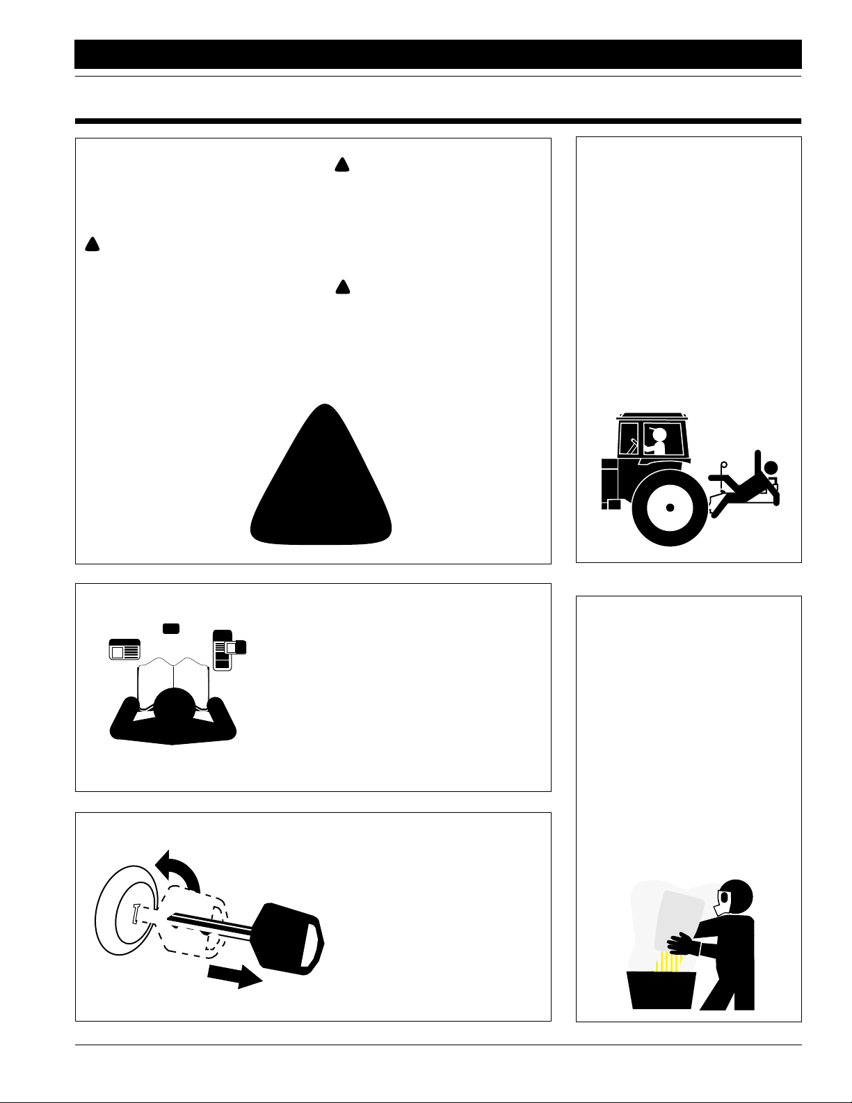
Keep Riders
Off Machinery
▲ Riders obstruct the operator’s
view. They could be struck by foreign objects or thrown from the
machine.
▲ Never allow children to operate
equipment.
OFF
For Your Protection
▲ Thoroughly read and understand
Safety Labels, page 4. Read all
instructions noted on them.
Shutdown and Storage
▲ Store implement in a area where
children do not play.
▲ Park implement on firm, level
ground. Lower machine to ground,
put tractor in park, turn off engine,
and remove the key.
▲ Block implement tires before
unhooking to prevent rolling.
Handle
Chemicals Properly
▲ Wear protective clothing.
▲ Handle all chemicals with care.
▲ Follow instructions on container
label.
▲ Use agricultural chemicals prop-
erly. Improper use can seriously
injure persons, animals, plants,
soil and property.
▲ Do not inhale smoke from any
type of chemical fire. This is a
serious health hazard.
▲ Store or dispose of unused chem-
icals as specified by the chemical
manufacturer.
8/14/
NTA3010 and NTA3510 Air Drill Implement SN Z1370- 160-219M
1
Page 4
Important Safety Information
Great Plains Mfg., Inc.
Use Safety
Lights and Devices
▲ Slow moving tractors, self-pro-
pelled equipment and towed
implements can create a hazard
when driven on public roads. They
are difficult to see, especially at
night.
▲ Flashing warning lights and turn
signals are recommended whenever driving on public roads. Use
lights and devices provided with
implement.
Transport
Machinery Safely
▲ Comply with state and local laws.
▲ Maximum transport speed for
implement is 20 mph. DO NOT
EXCEED. Never travel at a speed
which does not allow adequate
control of steering and stopping.
Some rough terrains require a
slower speed.
▲ Transport implement only when
hitched to a Great Plains air drill
cart.
▲ Keep clear of overhead power
lines when folding, unfolding or
transporting.
▲ Transport with transport locks in
place.
▲ Sudden braking can cause a
towed load to swerve and upset.
Reduce speed if towed load is not
equipped with breaks.
▲ Do not tow a load that weighs
more than 1.5 times the weight of
the towing vehicle.
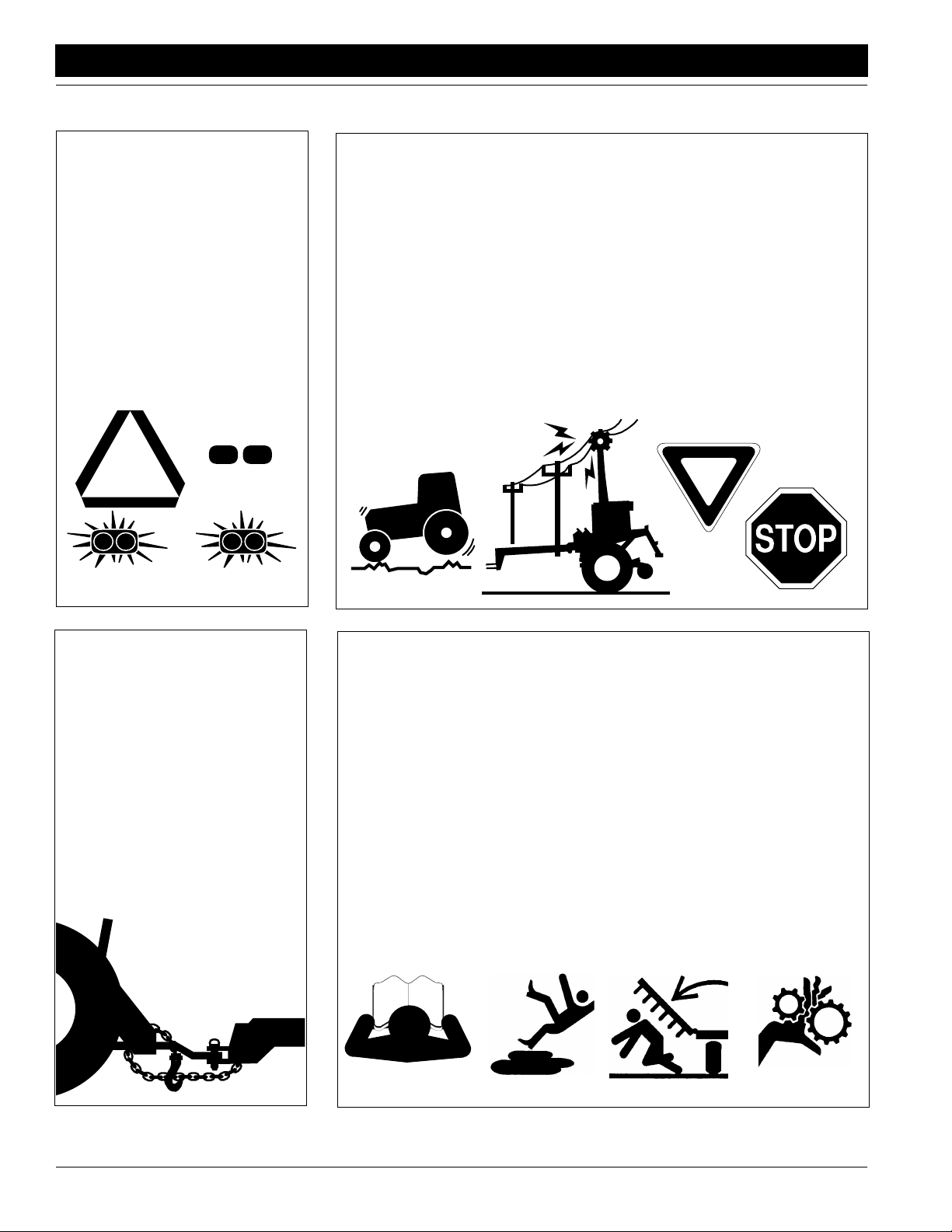
Use A Safety Chain
▲ Use a safety chain to help con-
trol drawn machinery should it
separate from the tractor drawbar.
▲ Use a chain with the strength
rating equal to or greater than
the total weight of the towed
machinery.
▲ Attach the chain to the tractor
drawbar support or other specified anchor location. Allow only
enough slack in the chain to permit turning.
▲ Do not use safety chain for tow-
ing.
Practice Safe Maintenance
▲ Understand procedure before
doing work. Use proper tools and
equipment. Refer to “Mainte-
nance and Lubrication,” page
28, for additional information.
▲ Work in a clean, dry area.
▲ Lower the implement to the
ground, put tractor in park, turn off
engine, and remove key before
preforming maintenance.
▲ Install all transport locks as
explained under Lifting the Imple-
ment,“Operating Instructions,”
page 14, before working underneath
the raised drill.
▲ Do not grease or oil implement
while it is in operation.
▲ Disk edges are sharp. Be careful
when working in this area.
▲ Disconnect battery ground cable
(-) before servicing or adjusting
electrical systems or before welding on implement.
▲ Inspect all parts. Make sure parts
are in good condition and installed
properly.
▲ Remove buildup of grease, oil or
debris.
▲ Remove all tools and unused
parts from implement before operation.
NTA3010 and NTA3510 Air Drill Implement SN Z1370- 160-219M 8/14/
2
Page 5
Great Plains Mfg., Inc.
Important Safety Information
Prepare for Emergencies
▲ Be prepared if a fire starts.
▲ Keep a first aid kit and fire extin-
guisher handy.
▲ Keep emergency numbers for
doctor, ambulance, hospital and
fire department near phone.
911
Wear
Protective Equipment
▲ Wear protective clothing and
equipment.
▲ Wear clothing and equipment
appropriate for the job. Avoid
loose fitting clothing.
▲ Wear suitable hearing protection
such as earmuffs or earplugs.
Prolonged exposure to loud noise
can cause hearing impairment or
loss.
▲ Avoid wearing radio headphones
while operating machinery. Operating equipment safely requires
full attention.
Avoid High
Pressure Fluids Hazard
▲ Relieve hydraulic pressure before
disconnecting lines. Escaping
fluid under pressure can penetrate the skin, causing serious
injury.
▲ Use a piece of paper or card-
board, NOT BODY PARTS, to
check for suspected leaks.
▲ Wear protective gloves and safety
glasses or goggles when working
with hydraulic systems.
▲ If an accident occurs, see a doc-
tor immediately. Any fluid injected
into the skin must be surgically
removed within a few hours or
gangrene may result.
Safety at All Times
Thoroughly read and understand the
instructions given in this manual
before operation. Refer to the Safety
Labels, page 4. Read all instructions
noted on them.
▲ Operator should be familiar with
all implement functions.
▲ Operate implement from the
driver’s seat only.
▲ Operate implement only when
hitched to a Great Plains air drill
cart. Do not modify implement for
use with other machines.
▲ Do not leave tractor or implement
unattended with engine running.
▲ Do not dismount a moving tractor.
Dismounting a moving tractor could
cause serious injury or death.
▲ Do not stand between the air drill
cart and implement while hitching.
▲ Keep hands, feet and clothing
away from power-driven parts.
▲ Wear snug-fitting clothing to avoid
entanglement with moving parts.
▲ Watch out for overhead power
lines, trees, etc., when raising,
folding, unfolding and transporting
the implement.
▲ Make sure all persons are clear of
working area. Stay clear of moving parts, and keep others away.
▲ Do not turn tractor too tight, caus-
ing implement to ride up on
wheels. This could result in injury
or equipment damage.
▲ Keep away and keep others away
when folding or unfolding implement.
▲ Avoid using implement tires as a
step.Tires not in contact with the
ground rotate easily.
▲ Use additional weight only on
implement center section. Only
use Great Plains weights.
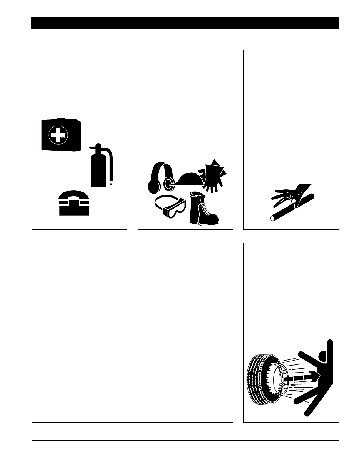
Tire Safety
▲ Tire changing can be dangerous
and should be preformed by
trained personnel using the correct tools and equipment.
▲ When inflating tires, use a clip-on
chuck and extension hose long
enough to allow you to stand to
one side–NOT in front of or over
the tire assembly. Use a safety
cage if available.
▲ When removing and installing
wheels, use wheel handling
equipment adequate for the
weight involved.
8/14/
NTA3010 and NTA3510 Air Drill Implement SN Z1370- 160-219M
3
Page 6
Important Safety Information
Safety Labels
Your implement comes equipped with all safety labels in place.
They were designed to help you safely operate your implement.
1. Read and follow label directions.
2. Keep all safety labels clean and legible.
3. Replace all damaged or missing labels. Order new labels
from your Great Plains dealer. Refer to this section for
proper label placement.
Great Plains Mfg., Inc.
4. When ordering new parts or components, request corresponding safety labels as well.
5. To install new labels:
a. Clean the area the label is to be placed.
b. Peel backing from label. Press firmly on surface
being careful not to cause air bubbles under label.
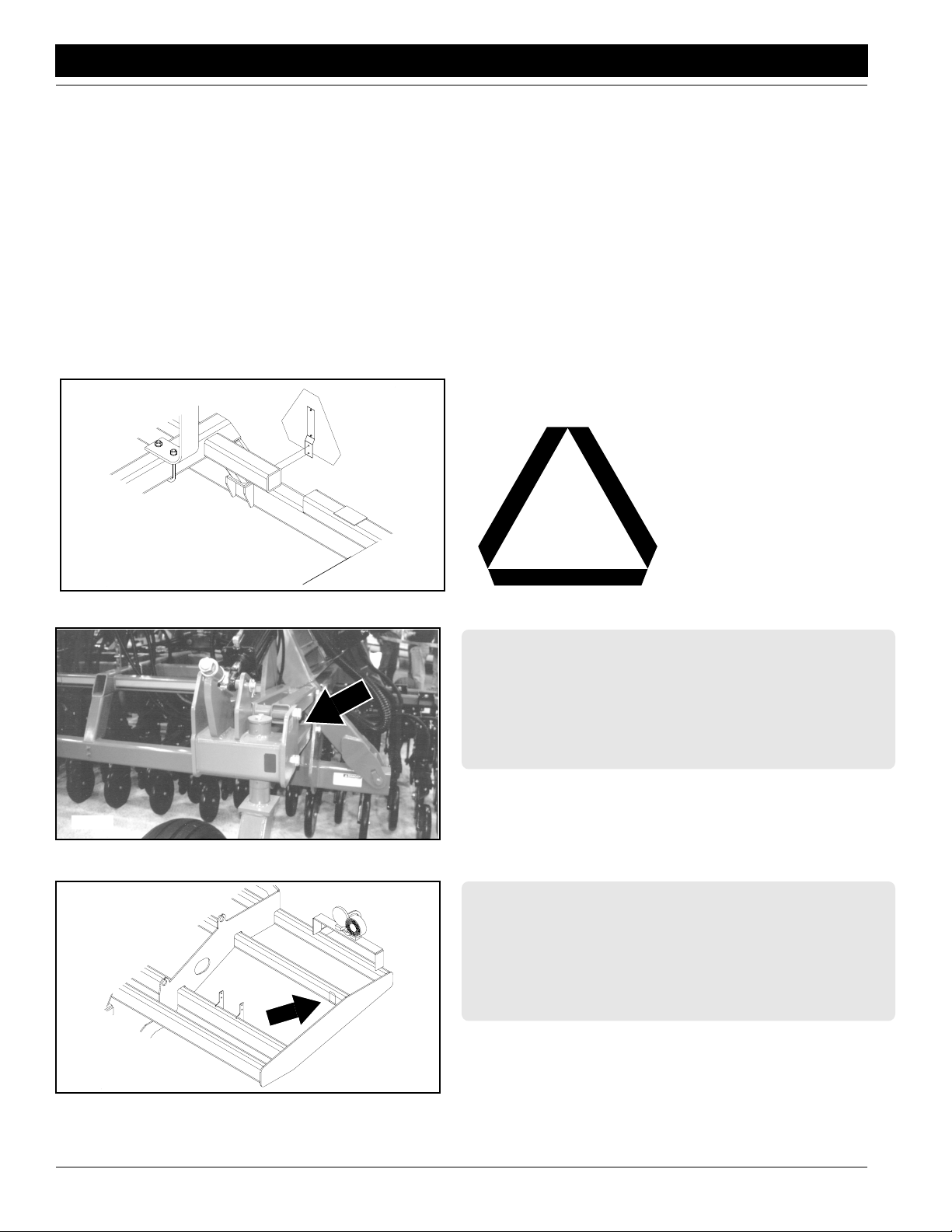
16174
16186
818-003C
Slow Moving Vehicle Label
838-265C
Amber Reflectors
(Both Rear Wheels)
838-265C
16185
NTA3010 and NTA3510 Air Drill Implement SN Z1370- 160-219M 8/14/
4
Amber Reflectors
(Both Ends, Center Section)
Page 7

Great Plains Mfg., Inc.
Important Safety Information
16174
16128
838-266C
Red Reflectors
(Both Rear Wheel
Arms)
838-266C
Red Reflectors
(Both Ends, Center Section)
8/14/
16196
16197
818-398C
Caution Tires Not a Step
(Both Wing Gauge Wheel
Arms)
818-398C
Caution Tires Not a Step
(Both Rockshaft Gauge
Wheels)
NTA3010 and NTA3510 Air Drill Implement SN Z1370- 160-219M
5
Page 8
Important Safety Information
16439
Great Plains Mfg., Inc.
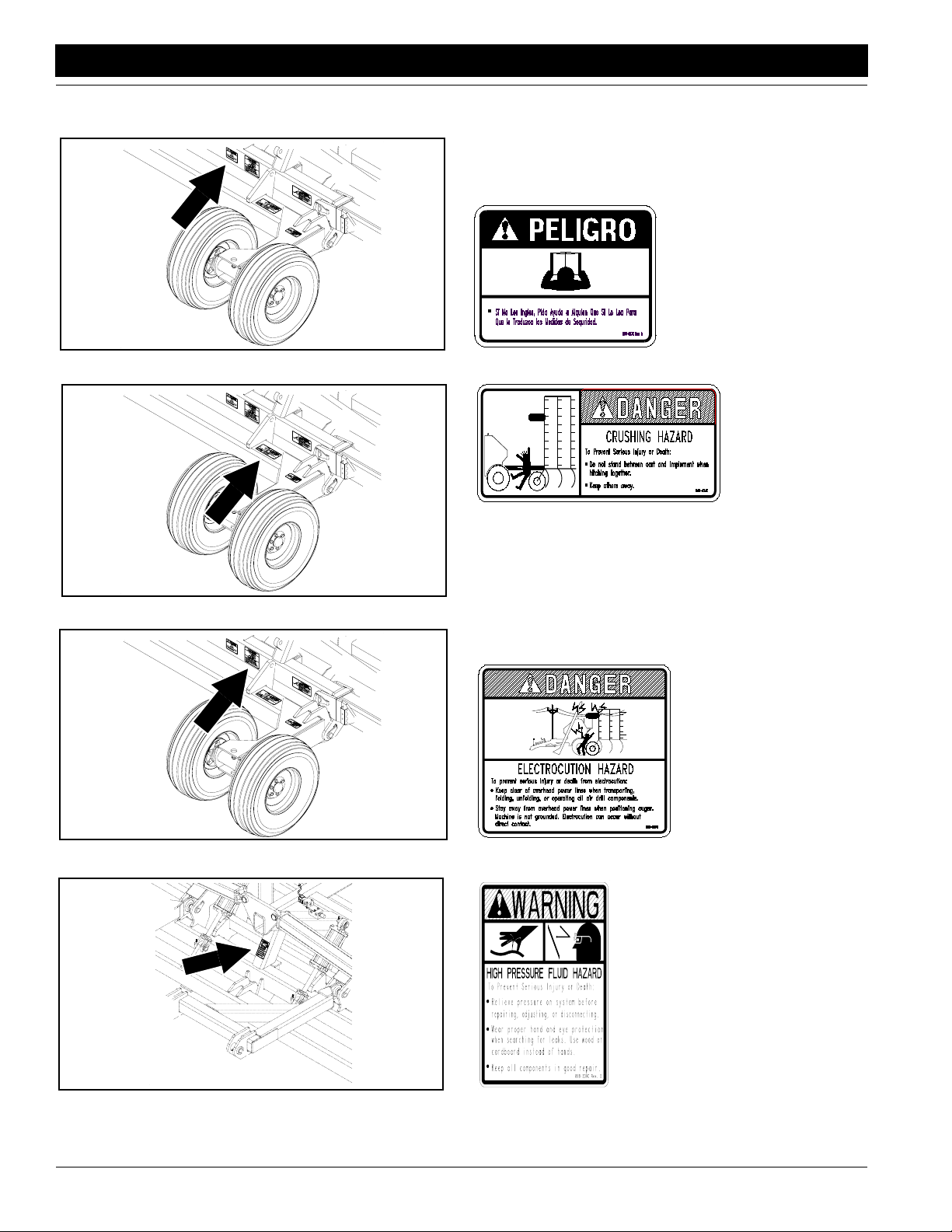
818-557C
Danger Cannot Read Eng
16439
16439
818-624C
Danger Crush AD/Implem (Both
Ends of Rockshaft)
818-627C
Danger Electrocution Aug
(Both Ends, Center Section)
818-339C
16184
NTA3010 and NTA3510 Air Drill Implement SN Z1370- 160-219M 8/14/
6
Warning High Pressure SML
Page 9
Great Plains Mfg., Inc.
Important Safety Information
16439
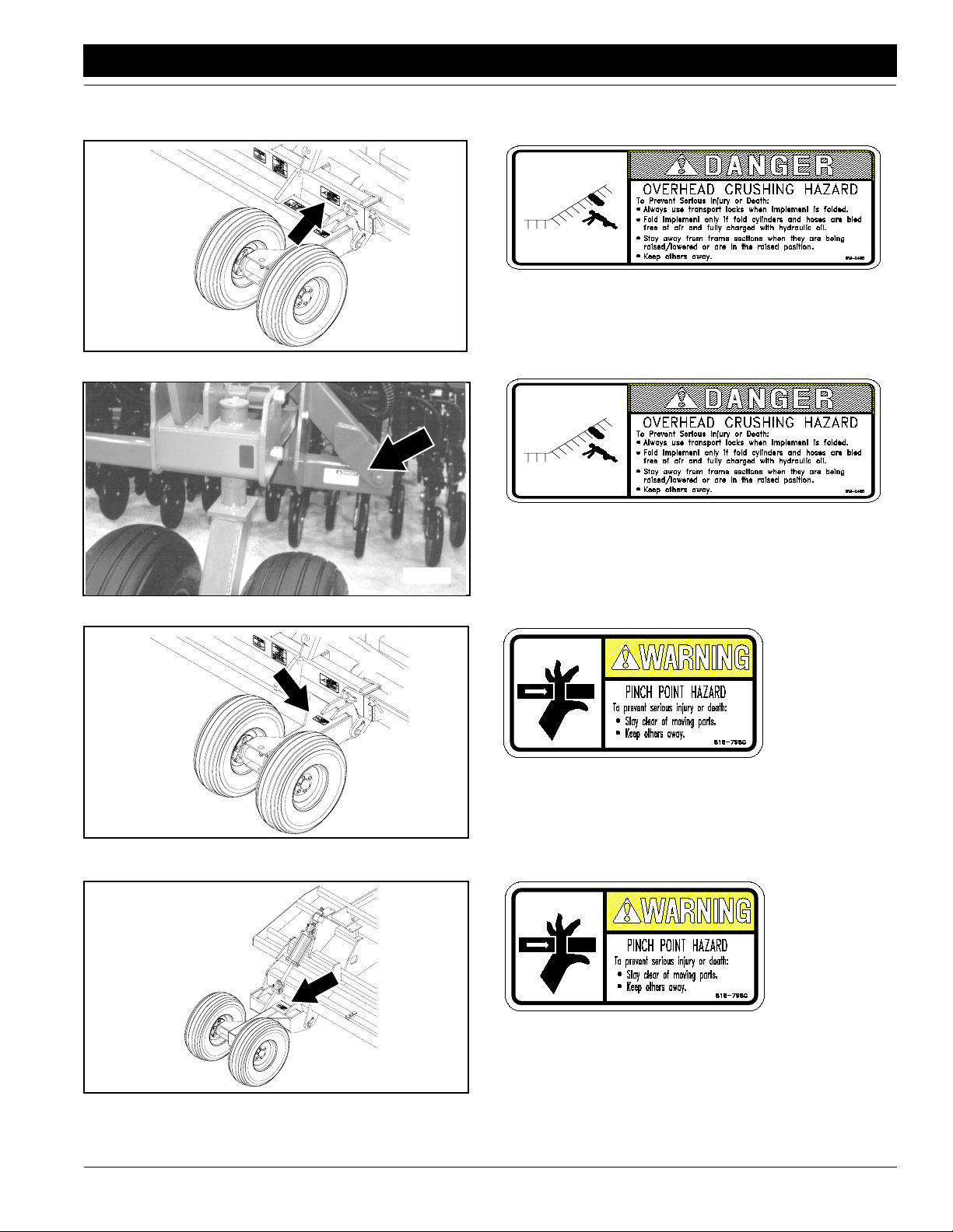
818-046C
Danger Charge Fold Cyl
(Both Ends, Center Section)
16174
16439
818-046C
Danger Charge Fold Cyl
(Both Ends, Center Section)
818-798C
Warning Pinch Point Gen
(Both Ends of Rockshaft)
8/14/
16438
818-798C
Warning Pinch Point Gen (Both
Wing Gauge Wheel Arms)
NTA3010 and NTA3510 Air Drill Implement SN Z1370- 160-219M
7
Page 10
Important Safety Information
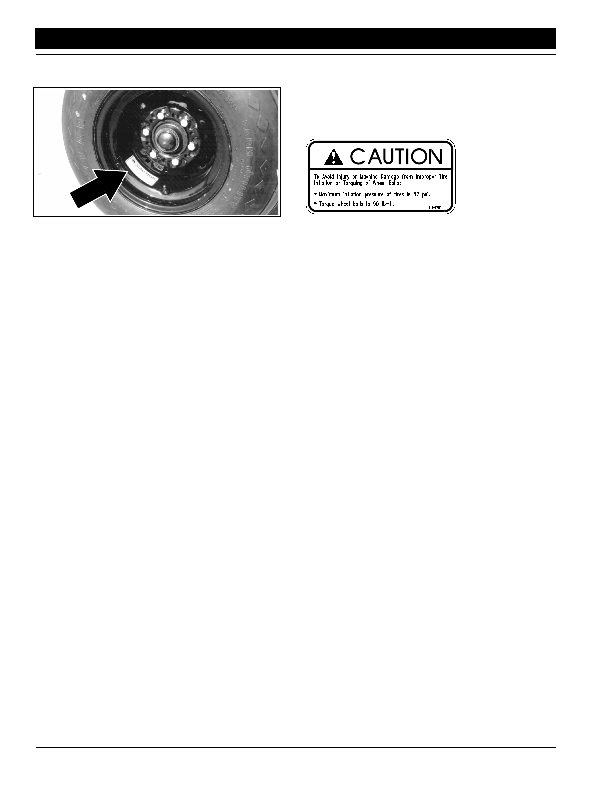
16247
Great Plains Mfg., Inc.
818-752C
Caution Tire 52 PSI
(All Wheels)
NTA3010 and NTA3510 Air Drill Implement SN Z1370- 160-219M 8/14/
8
Page 11
Great Plains Mfg., Inc.
Introduction
Introduction
Great Plains welcomes you to its growing family of new
product owners. This implement has been designed with
care and built by skilled workers using quality materials.
Proper assembly, maintenance and safe operation will
help you get years of satisfactory machine use from your
machine.
Description of Unit
The NTA3010 and NTA3510, serial numbers Z1370 and
lower (“Z1370-”) are seeding implements designed to tow
behind a Great Plains ADC1150 or ADC2220 Air Drill
Cart. For drills serial numbered Z1371+, see Operator
Manual 160-219M-A.
Working width is 30 or 35 feet. The implements are designed for no-till field conditions. Coulters open a narrow
seedbed. Disk-type, parallel-linkage openers follow each
coulter, widening the seedbed and delivering seed to the
trench.
The cart uses air to move seed through primary seed hoses to distribution towers on the implement. From the towers, seed is blown through secondary seed hoses to each
opener. The openers are equipped with press wheels,
which then firm the seedbed.
The implement is equipped with two hydraulic circuits. The
lift hydraulics raise the implement for field turns and folding. The fold hydraulics raise the wing sections for transport. The fold hydraulics also power the cart fan and
transfer weight from the implement center section to the
wings during seeding.
Intended Usage
Use this machine for seeding small grains and legumes in
no-till or minimum-till applications.
Using This Manual
This manual will familiarize you with safety, assembly, operation, adjustment, troubleshooting and maintenance.
Read this manual and follow the recommendations to help
ensure safe and efficient operation.
The information contained in this manual is current at
printing. Some parts may change to assure top performance.
Definitions
Right and left as used in this manual are determined by
facing the direction the machine will travel while in use unless otherwise stated.
IMPORTANT: A crucial point of information related to
the preceding topic. For safe and correct operation,
read and follow the directions provided before continuing.
Owner Assistance
If customer service or repair parts are needed contact
your Great Plains dealer. They have trained personnel,
parts and service equipment specially designed for Great
Plains products.
Your machine’s parts should only be replaced with Great
Plains parts. Always use the serial and model number
when ordering parts from your Great Plains dealer. The
serial-number plate is on the center section of the implement on a rear frame tube as shown in Figure A.
16195
Figure A
Serial Number Plate
Record your implement model and serial numbers here for
quick reference.
Model Number: _________________________________
Serial Number: _________________________________
Your Great Plains dealer wants you to be satisfied with
your new machine. If you do not understand any part of
this manual or are not satisfied with the service received,
please take the following actions:
1. Discuss the matter with your dealer service manager.
Make sure they are aware of anyproblems so they can
assist you.
2. If you are still not satisfied, seek out the dealership
owner or general manager.
3. For further assistance, write to:
Product Support
Great Plains Mfg. Inc.
Service Department
PO Box 5060
Salina, KS 67402-5060
NOTE: Useful information related to the preceding topic.
8/14/
NTA3010 and NTA3510 Air Drill Implement SN Z1370- 160-219M
9
Page 12
Section 1 Preparation and Setup
Section 1 Preparation and Setup
Great Plains Mfg., Inc.
This section covers implement preparation and setup. Before using the implement in the field, you must hitch the implement to your tractor, check that the hydraulics have
been bled of air, and check that the implement frame is level.
Hitching Cart to Implement
!
WARNING!
You may be severely injured or killed by being crushed between
the cart and implement. Always park and shut off the tractor before placing any body part between the cart and implement.
Refer to Figure 1-1.
1. Remove the pivot pins (1) from the lugs (2) on the center section of the implement frame.
2. With cart links tied up, slowly back cart toward the
center of the implement.
3. When ball swivels (3) are aligned with implement lugs,
drive pivot pins back in place. Secure with roll pins.
4. Connect the primary seed hoses to the cart meter
box. Connect the hoses left to right in the same order
towers are installed on the implement. Leave enough
slack in hoses so the drill can be fully raised, lowered,
folded and unfolded. Secure hoses to meter-box outlet
tubes using the 2 1/2-inch band clamps provided. Be
sure outer clamps do not interfere with meter-box door
latches. Refer to Figure 1-2.
14467
Figure 1-2
Band Clamp Position
NOTE: On 3010 implements, do not connect a seed hose
to the center outlet.
5. Connect lead from implement electrical harness to
outlet on rear of cart.
16430
Figure 1-1
Cart Link Up
NTA3010 and NTA3510 Air Drill Implement SN Z1370- 160-219M 8/14/
10
Page 13

Great Plains Mfg., Inc.
Section 1 Preparation and Setup
Hydraulic Hose Hookup
!
WARNING!
Escaping fluid under pressure can have sufficient pressure to
penetrate the skin causing serious injury. Avoid the hazard by
relieving pressure before disconnecting hydraulic lines. Use a
piece of paper or cardboard, NOT BODY PARTS, to check for
leaks. Wear protective gloves and safety glasses or goggles
when working with hydraulic systems. If an accident occurs, see
a doctor immediately. Any fluid injected into the skin must be
surgically removed within a few hours or gangrene will result.
Great Plains hydraulic hoses are color coded to help you
connect hoses to your tractor outlets.
Color Tie Hydraulic Function
Blue Lift Cylinders
Yellow Air Drill Fan and Fold Cylinders
To distinguish hoses on the same hydraulic circuit, refer to
plastic hose holders. See Figure 1-3. Hoses under the extended-cylinder symbol feed cylinder base ends. Hoses
under retracted-cylinder symbol feed cylinder rod ends.
Serial Numbers Z1100 and Earlier
Working left to right, hook hoses to cart as follows.
a. markers
b. markers
c. rod-end lift (1/2-inch hose)
d. base-end lift (1/2-inch hose)
e. rod-end fold (3/8 inch hose)
f. base-end fold (3/8-inch hose)
Serial Numbers Z1101 and Later
Working left to right, hook hoses to cart as follows.
a. Hook either marker hose to outlet A.
b. Hook remaining marker hose to outlet B.
c. Hook retracted blue (rod-end lift) to outlet C.
d. Hook extended blue (base-end lift) to outlet D.
e. Hook retracted yellow (rod-end fold) to outlet E.
f. Hook extended yellow (base-end fold) to outlet F.
(See Figure 1-5.)
g. Hook decaled sump hose to outlet G. (See Figure
1-5.)
17641
Figure 1-3
Hydraulic Hose Label
Connect implement hydraulic hoses to quick couplers on
rear of cart. See Figure 1-4.
17189
G
F
17256
Figure 1-5
Fold Hoses, Serial Numbers Z1101 and Later
NOTE: SAE O-ring and JIC 37˚ flare-type hose connections do not require sealant or high torque for a good seal.
Carefully check all hoses to make sure none will be damaged by implement operation. Reroute hoses or use cable
ties to keep hoses in a safe place.
Bleed the Hydraulics
To function properly, the hydraulics must be free of air. If
the hydraulics have not been bled, the implement will fold
in jerky, uneven motions or some frame sections will run
higher than others. If the hydraulics were not bled during
initial implement setup or if you replace a part in the hydraulic system during the life of the drill, complete the following procedures.
8/14/
Figure 1-4
Hose Connections
NTA3010 and NTA3510 Air Drill Implement SN Z1370- 160-219M
11
Page 14

Section 1 Preparation and Setup
!
WARNING!
Escaping fluid under pressure can have sufficient pressure to
penetrate the skin causing serious injury. Avoid the hazard by
relieving pressure before disconnecting hydraulic lines. Use a
piece of paper or cardboard, NOT BODY PARTS, to check for
leaks. Wear protective gloves and safety glasses or goggles
when working with hydraulic systems. If an accident occurs, see
a doctor immediately. Any fluid injected into the skin must be
surgically removed within a few hours or gangrene will result.
Bleeding Lift Hydraulics
The lift system is equipped with rephasing hydraulic cylinders that require a special procedure for bleeding air from
the system. Read and follow the procedure carefully.
!
WARNING!
You may be severely injured or killed by being crushed from a
falling implement. Always have transport locks in place and
frame sufficiently blocked up when working on implement.
1. Check hydraulic fluid level in tractor reservoir and fill to
proper level. Add fluid to system as needed while cycling new cylinders. You will need about 8 3/4 gallons
of oil to fill new cylinders.
2. Support implement frame sections with jack stands or
blocks.
3. With frame blocked and supported, unpin rod ends of
wheel cylinders. Pivot cylinders up and wire or otherwise safely support rod ends higher than base ends
as shown in Figure 1-6. You may need to remove the
gauge-wheel cylinders from the rockshaft so you can
orient them with rod ends higher than base ends.
Great Plains Mfg., Inc.
6. Again, check all hydraulic hoses, cylinders and fittings
for leaks. Recheck the tractor hydraulic reservoir. Fill
to the proper level.
7. Repin all cylinders.
Bleeding Fold Hydraulics
!
WARNING!
Before attempting to hydraulically lift the implement, the cart
must be attached to the implement and a tractor of sufficient
size. Failure to do so could result in severe equipment damage
and bodily injury or death.
1. Check the hydraulic fluid level in the tractor reservoir
and fill to the proper level. You will need about 6 gallons of oil to fill new cylinders.
2. Be sure implement is hitched to cart and tractor. See
Hitching Cart to Implement, page 10.
3. Hydraulically raise the implement and install rockshaft
and lift-assist transport locks. Refer to Lifting the Im-
plement,“Field Operations,” page 15.
4. Unpin rod end of fold cylinders. Block, wire or otherwise safely support the rod ends as shown in Figure 17 so they will not contact anything when extended.
Figure 1-7
Fold Cylinder, Rod End Supported
IMPORTANT: Failure to block cylinders before extending will cause machine damage.
5. Turn the hydraulic selector valve to the Fold/Unfold po-
16238
Figure 1-6
Rod End Supported
4. With the tractor engine at idle speed, energize the lift
hydraulics. When the gauge-wheel cylinders on wings
have extended completely, hold the remote lever on
for one minute. Check all hydraulic hoses, cylinders
and fittings for leaks.
5. Retract the cylinder rods. Extend the rods again and
hold the remote lever on for one more minute. Repeat
this step two more times.
NTA3010 and NTA3510 Air Drill Implement SN Z1370- 160-219M 8/14/
12
sition. Refer to Folding the Implement,“Operating In-
structions,” page 15.
6. Cycle the cylinders completely in and out three times
to remove all air from the fold system. Inspect all hoses, cylinders and fittings for oil leaks.
7. Extend cylinders and repin to lugs.
8. Recheck the tractor hydraulic reservoir and fill to the
proper level.
9. Slowly fold and unfold implement. Check for hydraulic
leaks. Be aware of any pinch points that might cause
damage or accelerate wear on hydraulic hoses.
16432
Page 15

Great Plains Mfg., Inc.
Section 1 Preparation and Setup
Level Frame Side to Side
All frame sections must be level to maintain even seeding
depth. Before using the implement in the field, follow these
steps to make sure the implement is level side-to-side.
Periodic frame-leveling adjustments should not be necessary, but if you are having problems with uneven depth,
check drill levelness and follow these procedures.
1. Check that the lift hydraulics are free of air and full of
oil. See Bleeding the Lift Hydraulics, page 12.
2. Unfold and lower the implement. Make sure the lift cylinders are fully retracted, then block up or otherwise
support the frame.
3. Take a reference measurement by laying a straight
edge across the top of the two coulter mount tubes on
the center section. Measure from the bottom of the
straight edge to the center of one rockshaft-wheel axle
as shown in Figure 1-8. Because rockshaft gauge
wheels are not adjustable, all adjustments will be
made relative to this measurement.
5. If the wing measurement differs from the reference
measurement, remove the pin from the rod end of the
wing-gauge-wheel cylinder. Block or support the wing
gauge wheels so the distance from the bottom of the
straight edge to the center of the wing-gauge-wheel
axle is the same as the reference measurement taken
in step 3.
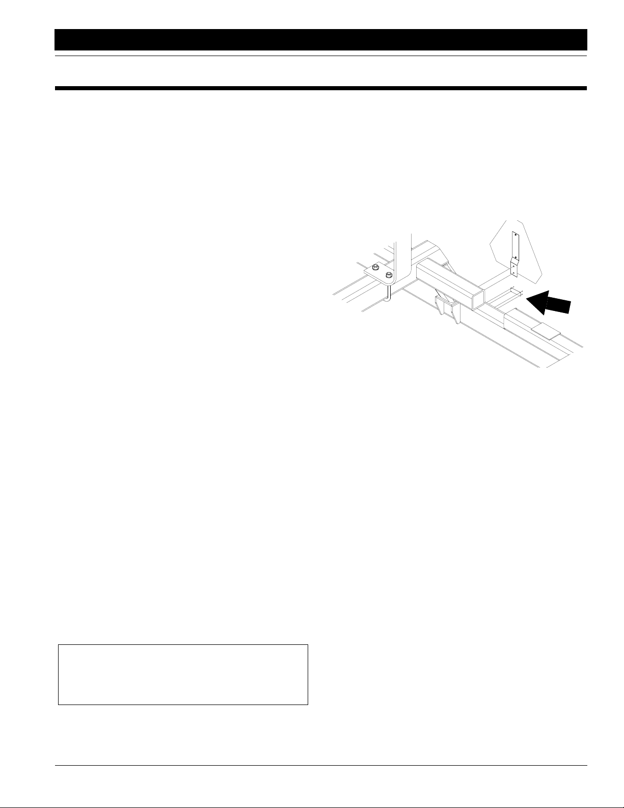
6. Loosen the nuts (1) on the cylinder eye bolt as shown
in Figure 1-10. Move the eye bolt in or out until the rod
end of the cylinder can be pinned to its lug. Secure the
eye bolt by tightening the nuts.
1
16443
Figure 1-10
Wing-Cylinder Adjustment
Reference
Measurement
Figure 1-8
Frame Leveling Reference Measurement
16235
4. Move the straight edge to one of the wings. Measure
the distance from the bottom of the straight edge to
the center of wing-gauge-wheel axle as shown in Figure 1-9.
7. Repeat steps 4, 5 and 6 for other wing section.
Level Frame Front to Rear
The front-to-rear levelness of your drill will also affect
seeding depth. If the lift-assist wheels raise the rear of the
implement higher relative to the front, the openers may operate at the wrong angle. The opener bodies should run
parallel to the ground. If they do not, level the angle which
the implement runs by following these instructions.
1. Check that the lift hydraulics are bled of air and full of
oil. See Bleeding the Lift Hydraulics, page 12.
2. Turn the nuts (1) on the eye bolt on the lift-assist cylinder shown in Figure 1-11.
• To raise rear of implement, move eye bolt in toward
drill.
• To lower rear of implement, move eye bolt out.
3. Repeat for other lift-assist wheel.
1
8/14/
16236
Figure 1-9
Frame Leveling Adjustment Measurement
Adjustment
Measurement
16127
Figure 1-11
Rear Lift-Assist Wheel Adjustment
NTA3010 and NTA3510 Air Drill Implement SN Z1370- 160-219M
13
Page 16

Section 2 Operating Instructions
Section 2 Operating Instructions
Great Plains Mfg., Inc.
This section covers general operating procedures. Experience, machine familiarity and the following information will
lead to efficient operation and good working habits. Carefully read the operator’s manual for the air drill cart you will
be using with the implement. Always operate farm machinery with safety in mind.
General Description
The implement has two hydraulic circuits. One circuit lifts
the implement. A second powers the cart fan, implement
folding and weight transfer.
An electric circuit powers a clutch on the cart metering
system and a solenoid valve on the implement weighttransfer system. The circuit has a master switch in the
tractor cab that powers the entire circuit. An automatic
switch on the implement rockshaft engages and disengages the clutch as the implement is lowered and raised. The
in-cab switch must be on during field use and off during
folding, unfolding and transport.
!
WARNING!
Escaping fluid under pressure can have sufficient pressure to
penetrate the skin causing serious injury. Avoid the hazard by
relieving pressure before disconnecting hydraulic lines. Use a
piece of paper or cardboard, NOT BODY PARTS, to check for
leaks. Wear protective gloves and safety glasses or goggles
when working with hydraulic systems. If an accident occurs, see
a doctor immediately. Any fluid injected into the skin must be
surgically removed within a few hours or gangrene will result.
Rephasing Lift System
Over a period of normal use the cylinders may get out of
phase. This will cause some implement sections to run
higher than others. To rephase the cylinders:
1. Raise the implement completely and hold the hydraulic remote lever on for several seconds until all cylinders are fully extended. Do this every time you raise
the implement out of the ground.
2. When all cylinders are fully extended, momentarily reverse the hydraulic remote lever to retract the system
1/2 inch to maintain levelness.
Lift System Transport Locks
The lift system has transport locks for the rockshaft and
lift-assist cylinders. Use these locks every time you raise
the drill for maintenance, lubrication, folding or transport.
To install the rockshaft locks, remove the locks from storage on the implement frame. Pin the locks in place on the
raised implement as shown in Figure 2-1.
Pre-start Checklist
1. Lubricate the implement as indicated under Lubrication,“Maintenance and Lubrication,” page 28.
2. Check all tires for proper inflation as indicated on Tire
Inflation Chart,“Appendix,” page 33.
3. Perform all beginning-of-season and daily service
items under General Maintenance,“Maintenance
and Lubrication,” page 28.
4. Check the implement for worn or damaged parts. Repair or replace them before going to the field.
5. Check all nuts, bolts and screws. Refer to Torque Val-
ues Chart,“Appendix,” page 33.
Lifting Implement
Your air drill implement is equipped with rephasing hydraulic cylinders in a master-slave configuration. For proper
operation the system must be free of air. Refer to Bleed
Hydraulics,“Preparation and Setup,” page 11.
16165
Figure 2-1
Rockshaft Transport Lock in Place
To install the lift-assist locks, remove the locks from storage. Figure 2-2 shows the left lock in storage.
16248
Figure 2-2
Lift-Assist Transport Lock, Storage
NTA3010 and NTA3510 Air Drill Implement SN Z1370- 160-219M 8/14/
14
Page 17

Great Plains Mfg., Inc.
Section 2 Operating Instructions
Place the locks over the extended cylinder rods as shown
in Figure 2-3 and pin in place.
16167
Figure 2-3
Lift-Assist Transport Locks in Place
Folding Implement
The air drill uses one hydraulic circuit to power the cart fan
and implement folding. A hydraulic selector valve and an
electric rocker switch control these operations. To fold the
implement, the in-cab rocker switch must be off and the
selector valve must be turned to fold/unfold position.
!
DANGER!
Overhead crushing hazard. To prevent serious injury or death:
• Always use transport locks when implement is folded.
• Fold implement only if fold hydraulics are bled free of air and
fully charged with hydraulic oil.
• Stay away from frame sections when they are being raised or
lowered or are in the raised position.
• Keep away and keep others away when folding or unfolding
implement.
2. Turn hydraulic selector valve to fold/unfold position as
shown in Figure 2-4.
17230
Figure 2-4
Selector Valve, Fold/Unfold
3. Turn in-cab rocker switch off.
NOTE: The in-cab rocker switch is mounted on the system
monitor. If the switch and monitor have not been installed,
refer to the air drill cart operator’s manual for instructions.
4. Raise implement until all lift cylinders are completely
extended.
IMPORTANT: Never fold implement without first completely raising implement and installing transport locks
or serious equipment damage may occur.
5. Install transport locks as described under Lifting Im-
plement, page 14.
6. Check that wing fold pins are removed (1) and marker
stop pins are installed (2) in the wing braces as shown
in Figure 2-5.
!
DANGER!
Electrocution hazard. To prevent serious injury or death from
electric shock, keep clear of overhead power lines when transporting, folding, unfolding or operating all air drill components. Machine is not grounded. Electrocution can occur
without direct contact.
1. Fold implement on level ground. Be aware of clearance required to fold implement. Refer to “Specifica-
tions and Capacities,” page 32.
8/14/
1
2
Figure 2-5
Wing Fold Pin Removed
7. Set tractor at slow idle speed.
8. Energize tractor hydraulics for fold system. Slowly fold
implement.
NTA3010 and NTA3510 Air Drill Implement SN Z1370- 160-219M
16217
15
Page 18

Section 2 Operating Instructions
Great Plains Mfg., Inc.
9. Insert wing fold pins to secure folded wings as shown
in Figure 2-6.
16166
Figure 2-6
Folded Wings Secured
10. Do not remove transport locks from folded implement.
IMPORTANT: Marker attachments will increase the
folded height of the implement. Be aware of the additional clearance needed for folding and transporting.
Refer to “Specifications and Capacities,” page 32.
2. Remove the stop collars shown in Figure 2-8 from the
hydraulic fold cylinders.
16213
Figure 2-8
Stop Collar on Fold Cylinders
3. Follow steps under Folding the Implement, page 15.
When first folding after removing marker stops, carefully watch towers and hoses to be certain they are not
damaged by folding wings.
Folding Without Markers
If your implement is not outfitted with marker attachments,
you can reduce the height of the folded implement to ease
transport.
1. Remove marker-stop bolt and spacer from the wing
braces. Figure 2-7 shows the wing braces without the
marker stop.
16168
Figure 2-7
Folded Wings Without Marker Stop
NTA3010 and NTA3510 Air Drill Implement SN Z1370- 160-219M 8/14/
16
Page 19

Great Plains Mfg., Inc.
Section 2 Operating Instructions
Unfolding Implement
!
DANGER!
Overhead crushing hazard. To prevent serious injury or death,
always use transport locks when folding or unfolding implement.
• Always use transport locks when implement is folded.
• Fold implement only if fold hydraulics are bled free of air and
fully charged with hydraulic oil.
• Stay away from frame sections when they are being raised or
lowered or are in the raised position.
• Keep away and keep others away when folding or unfolding
implement.
!
DANGER!
Electrocution hazard. To prevent serious injury or death from
electrocution, keep clear of overhead power lines when transporting, folding, unfolding or operating all air drill components. Your machine is not grounded. Electrocution can occur
without direct contact.
1. Park implement on level ground. Be aware of clear-
ance required to unfold implement.
2. Remove wing fold pins.
3. Check that hydraulic selector valve is in fold/unfold po-
sition.
4. Check that in-cab rocker switch is off.
5. Set tractor at low idle speed.
6. Energize tractor hydraulics for fold system and slowly
unfold implement.
7. Continue to unfold implement only until each wing
gauge wheel rests on ground.
8. When sections are unfolded, immediately turn selec-
tor valve to field position as shown in Figure 2-9.
Field Operations
To operate the seed-metering and weight-transfer systems, the in-cab rocker switch must be on. A height switch
on the implement rockshaft will automatically turn seed
metering and weight transfer off and on as you raise and
lower the drill for field turns.
!
WARNING!
Operate implement only when hitched to a Great Plains air drill
cart. Modifying the implement for use with other machines
could lead to field or road accidents, serious injury or death.
For normal seeding operations:
1. Check that the in-cab rocker switch is on.
2. Turn the hydraulic selector valve to the Field position
as shown in Figure 2-9.
3. Energize tractor hydraulics for fan. Lock hydraulic lever in place for continuous operation.
4. Run fan for at least 15 minutes before seeding. Hydraulic fluid must be warm before fan and wing down
pressure will operate properly.
5. Watch the monitor and adjust fan speed by increasing
or decreasing hydraulic flow from the tractor. Use the
following guidelines and the fan speed chart to properly adjust fan speed.
• Higher fan speeds improve seed distribution, but high
fan speeds also increase the chance of seed damage
and bounce.
• At first, adjust fan speed to the high end of the range
suggested in the fan speed chart. Watch for excessive
seed cracking and seed bounce from the furrow, then
reduce fan speed if necessary.
• Follow the chart below as a guide. Actual fan speeds
will vary with seeding rates, seed weights and seed
size. Increase fan speed for heavier seeding rates or
seed. Reduce fan speed for lighter seeding rates and
seed more prone to cracking.
Fan Speed Chart
Seeds Fan RPM
8/14/
17229
Figure 2-9
Selector Valve, Field Position
Sunflowers 2,250 - 3,000
Wheat 3,250 - 4,000
Soybeans 2,750 - 3,500
Milo 3,250 - 4,000
6. Pull forward, lower drill and begin seeding. If the metering system does not turn off and on as the implement is raised and lowered, refer to Electric Clutch
Switch Adjustment,“Adjustments,” page 23.
When the implement is lowered, weight will be transferred from the center to wing sections. Wing down
pressure can be adjusted. Refer to Wing Down-Pres-
sure Adjustment,“Adjustments,” page 22.
NTA3010 and NTA3510 Air Drill Implement SN Z1370- 160-219M
17
Page 20

Section 2 Operating Instructions
Great Plains Mfg., Inc.
7. When finished seeding, turn the in-cab switch off and
the selector valve to Fold/Unfold before transporting.
Opener Operation
• Raise implement before turning. Never back up or turn
sharply with openers in the ground. Doing so will plug
openers and may damage equipment.
• Be aware of a 5- to 10-foot delay needed for the seed to
reach the openers. If you stop in the middle of the field,
lift the drill and back up 10 feet before proceeding.
!
WARNING!
Crushing hazard. You could be seriously injured or killed if the
raised implement falls. Do not crawl among the openers unless
transport locks are installed, the implement is securely blocked,
and the tractor key is turned off and removed.
• Check periodically for plugged openers and hoses. With
the fan running and the drill raised, hand crank the metering system. Look below each opener for seed or fertilizer.
• For information on opener adjustments, see Opener Ad-
justment,“Adjustments,” page 22, and Level Frame
Front to Rear,“Preparation and Setup,” page 13. For
more information on troubleshooting opener problems,
see “Troubleshooting,” page 25.
Marker Operation
If you have purchased markers, the following will help you
integrate the markers with the air drill hydraulic system.
Carefully read the marker manufacturer’s instructions for
safe installation, operation and adjustment.
Marker attachments are controlled by the same hydraulic
circuit as the cart auger. To operate the markers, move the
hydraulic diverter valve on the cart tongue up to the marker position as shown in Figure 2-10.
Markers
Auger
16221
Figure 2-10
Auger/Marker Hydraulic Diverter
IMPORTANT: Marker attachments will increase the
height of the folded implement. To avoid equipment
damage and injury during implement folding or transporting, consider the extra clearance needed. Refer to
“Specifications and Capacities,” page 32, for folded
dimensions.
Transporting
!
DANGER!
Electrocution hazard. To prevent serious injury or death from
electric shock, keep clear of overhead power lines when transporting, folding, unfolding or operating all air drill components. Machine is not grounded. Electrocution can occur
without direct contact.
!
WARNING!
Towing the drill at high speeds or with a vehicle that is not
heavy enough can lead to loss of vehicle control. Loss of vehicle
control can lead to serious road accidents, injury and death. To
reduce the hazard:
• Do not exceed 20 mph.
• Do not tow a drill that, when fullyloaded, weighs more than
1.5 times the weight of the towing vehicle.
!
WARNING!
The implement is designed to hitch to the air drill cart only.
Hitching the implement to any vehicle other than a Great Plains
air drill cart will create an unstable towing load and can lead
to road accidents, injury and death. To avoid the hazard, transport the implement only when hitched to an Great Plains air
drill cart.
Before transporting the implement, check and practice the
following items.
Minimum Towing Vehicle Weight
Hitched to ADC2220: 25,550 pounds
Hitched to ADC1150: 21,675 pounds
Transport Locks. Check that all transport locks and wing
lock pins are in place. Refer to Lifting the Implement, page
14, and Folding the Implement, page 15.
Rocker Switch Off. Check that the in-cab rocker switch is
turned off while transporting.
Stopping Distance. Keep the combined weight of the implement and cart in mind. Allow sufficient stopping distance at all times. Reduce speed prior to making any turns
or other maneuvers.
Bystanders. Check that no one is in the way before moving. Do not allow anyone to ride on the air drill.
Clearance. Know the dimensions of the cart and implement in transport position and follow a route that provides
adequate clearance from all obstructions. Be especially
observant of low overhead power lines. Refer to “Specifi-
cations and Capacities,” page 32, for folded dimensions.
Tires. Check that all tires are properly inflated as listed on
Tire Inflation Chart,“Appendix,” page 33.
Road Rules. Comply with all federal, state and local laws
when transporting on public roads.
NTA3010 and NTA3510 Air Drill Implement SN Z1370- 160-219M 8/14/
18
Page 21

Great Plains Mfg., Inc.
Section 2 Operating Instructions
Warning Lights. To use the implement warning lights,
your tractor must be equipped with a seven-pin electrical
connector. Always use implement warning lights when
transporting the air drill.
Watch Traffic. Remember that the cart bins and folded
implement wings can obstruct your view. Be prepared for
sudden maneuvers from following vehicles.
Marker Attachments. If you have installed optional marker attachments, refer to the manufacturer’s instructions for
closing the marker hydraulic valves for safe transport.
NOTE: Failure to close marker hydraulic valves during
transportation could result in equipment or property damage.
Parking
Perform the following steps when parking the drill. Refer to
Storage,“Maintenance and Lubrication,” page 28, for in-
formation on long-term storage preparation.
1. Raise the implement and install transport locks as ex-
plained under Lifting the Implement, page 14.
2. Park implement on a firm, level area.
3. Securely block the tires to prevent rolling.
4. Unhook electrical lines.
5. Release pressure on the hydraulic system, then dis-
connect hydraulic lines. Check that hose ends do not
rest on the ground.
8/14/
NTA3010 and NTA3510 Air Drill Implement SN Z1370- 160-219M
19
Page 22

Section 3 Adjustments
Section 3 Adjustments
Great Plains Mfg., Inc.
Seeding Depth
To correctly adjust seeding depth, you need a good understanding of how the coulters, openers and press wheels
work. The following is an introduction to how the no-till
coulter and double-disk openers are designed to control
planting depth.
Coulters
A no-till coulter is mounted independent and directly
ahead of each opener. Each coulter cuts through heavy
trash to make a groove in the soil for the openers. The
coulters are mounted on the frame, so coulter cutting
depth changes as the drill is raised and lowered. Coulter
down force can be changed by adjusting coulter spring
length, adding weights, moving the hydraulic depth stop,
or changing the height of individual coulter mounts. Refer
to Coulter Adjustments, this page, for information on how
to make these adjustments.
Openers
The openers are mounted on the implement frame with
parallel links. This allows the opener arms to move up and
down while keeping the openers in-line with the coulters.
This parallel-action mounting also maintains the contact
point throughout the opener’s depth range. Opener double
disks widen the coulter groove to make a seed bed. A seed
tube mounted between the disks delivers seed to the
trench. The down force needed by each opener to cut and
widen the coulter groove is supplied by two springs nested
in the parallel linkage. Adjusting these springs changes
opener down-force. Refer to Opener Adjustment, page 22,
for information on how to make this adjustment. When
making seeding depth adjustments, keep in mind that
openers will not run any deeper than coulters till the soil.
Press Wheels
Attached to the rear of each opener is one of several optional press wheels. The press wheel provides two important functions.
First, the press wheels close the furrow, gently pressing
the soil over the seed. To provide consistent seed firming,
the press wheels are free to move downward from the normal operating position. This system maintains pressing
action even if the opener arm is lifted when the disks encounter obstructions.
Second, the press wheels provide opener depth control.
The higher the press wheels run relative to the double
disks, the deeper seed will be placed. To maintain a consistent depth, upward press wheel movement is restricted
by an independently adjustable stop on each opener. Refer to Press Wheel Adjustment, page 21, for information on
how to make this adjustment.
Coulter Adjustments
The air drill is factory assembled so that when the coulters
are set to run 2 inches deep, the seeding depth is approximately 1 inch. This is a good baseline setting for most
seeding conditions. You have the option of changing settings on the entire implement or individual coulters as field
conditions warrant.
!
WARNING!
Crushing hazard. You may be severely injured or killed if the implement falls on or runs over you during maintenance. Always
turn off tractor and remove the key before making any adjustments or performing maintenance. Securely block and install
transport locks on raised implement before working under or
around it.
Hydraulic Depth Control
The lift cylinders on the implement control coulter depth. A
valve in the hydraulic line on the left-wing, gauge-wheel
cylinder regulates depth. Figure 3-1 shows the valve and
knob used to adjust coulter depth.
Raise Coulters
Lower Coulters
16271
Figure 3-1
Wing Gauge-Wheel Cylinder Depth Control Stop
Turn the knob clockwise to lower the coulters. Each clockwise rotation will lower the coulters about 3/16 inch. Make
depth adjustments withthe implement slightly raised.After
adjusting the valve, raise and lower the implement several
times and recheck coulter depth.
NTA3010 and NTA3510 Air Drill Implement SN Z1370- 160-219M 8/14/
20
Page 23

Great Plains Mfg., Inc.
Section 3 Adjustments
Coulter Springs
Coulter springs are preset at 10 inches, giving the coulters
an initial operating force of 400 pounds. This setting is adequate for many difficult no-till conditions. For lighter no-till
conditions where rocks or other obstructions are a problem, you can lengthen the springs to protect the coulters
from impact. Refer to the chart below for spring length and
corresponding coulter down force.
Spring Length Coulter Down Force
10 1/4 in 300 lb
10 in 400 lb
9 3/4 in 525 lb
NOTE: Any attempt to reset the coulter spring length
shorter than 9 3/4 inches may contribute to premature failure of parts and warranty shall be voided. If additional
force is needed, add weights to the implement.
Weights
!
WARNING!
Crushing hazard. Weights that are not properly secured or positioned could fall off the implement during folding, field operation or transport and cause severe injury or death to
bystanders. Adding weight to the wings could cause a wing to
drop suddenly during folding and severely injure or kill bystanders. Do not add more than eight weights (four pairs) to the
implement. Use only Great Plains weights, part number 163233A, as additional weight on the implement. Do not add
weights to the wing sections.
Many no-till conditions will require additional weight for
sufficient coulter depth. Additional weights are available
from your Great Plains dealer. Up to eight 700-pound
weights can be evenly distributed over the center section
of the implement. Refer to the weight chart below to see
the results of adding weights.
Individual Coulters
Individual coulters that run in tire tracks can be lowered if
desired. To raise or lower individual coulters:
1. Loosen the mounting clamps and adjust the coulter to
the desired height.
2. To retighten clamps, refer to Figure 3-2. Snug the hexhead clamp bolts (1) just until the u-bolts are tight on
each side of the spring bar.
3. Tighten nuts (2) on u-bolts.
4. Finish tightening hex-head clamp bolts.
10300
Figure 3-2
Individual Coulter Mounting
NOTE: Ground clearance on lowered coulters will be reduced when the implement is in the raised position.
Press Wheel Adjustment
To change the height of the press wheel, lift and slide the
“T” handle on top of the opener arm as shown in the Figure
3-3.
• To lower the press wheel for a more shallow seeding,
slide the handle toward the implement.
• To raise the press wheel for deeper seeding, slide the
handle away from the implement.
NTA3510 NTA3010
7 1/2-Inch
Rows
Empty Drill 18,800 lb 16,500 lb 17,650 lb 15,700 lb
Per
Coulter,No
Weights
Per
Coulter,
Eight
Weights
8/14/
342 lb 413 lb 368 lb 493 lb
451 lb 563 lb 493 lb 603 lb
10-Inch
Rows
7 1/2-Inch
Rows
10-Inch
Rows
Figure 3-3
Press Wheel Adjustment
NTA3010 and NTA3510 Air Drill Implement SN Z1370- 160-219M
12919
21
Page 24

Section 3 Adjustments
Great Plains Mfg., Inc.
Wing Down Pressure Adjustment
The implement isequipped with weight-transfer hydraulics
to evenly distribute weight between the frame sections.
While seeding, hydraulic down pressure is placed on the
wings so all frame sections run at the same depth. If there
is not enough weight on the wings, they will run higher
than the center section.
To adjust wing down pressure,
1. Check that in-cab rocker switch is on and selector
valve is turned to field position. Refer to Figure 2-9,
page 17.
2. Lower implement so openers are on ground.
3. Engage fan hydraulics.
4. Turn pressure-control valve shown in Figure 3-4.
When facing valve,
• increase weight on wing sections by turning clock-
wise.
• decrease weight on wings by turning counterclock-
wise.
Typical pressures on gauge shown in Figure 3-4
should be 200 to 600 psi.
IMPORTANT: Do not exceed 800 psi. Exceeding 800
psi could cause equipment damage.
Opener Adjustment
Seed cannot be placed any deeper than coulter cutting
depth. Before adjusting openers, check that coulters are
running deep enough and that the frame is level from front
to rear. Refer to Coulter Adjustments, page 20, and Level
Frame Front to Rear, “Preparation and Setup,” page 13.
Adjust the parallel-linkage openers with the tool stored on
the rear tube of the center frame section.
To increase or decrease opener down-force, position the
tool in the holes on the left and right mounting plates
shown in Figure 3-5 and pull down on the adjuster. This
will reposition the springs and change opener down force.
Spr
ing Mounting Plate
16128
Figure 3-5
Parallel-Linkage Opener Springs
17229
Figure 3-4
Pressure-Control Valve and Gauge
5. When satisfied with pressure reading, raise implement while watching pressure gauge. Gauge reading
should drop as you raise implement.
NOTE: If wings run lower than center section when at minimum pressure setting, add weight tocenter section. Refer
to Weights, page 21.
Minimum and maximum down-force settings are indicated
by the position of spring adjuster as shown in Figure 3-6.
12104
Minimum Force
Figure 3-6
Parallel-Linkage Spring Adjustments
Maximum Force
NTA3010 and NTA3510 Air Drill Implement SN Z1370- 160-219M 8/14/
22
Page 25

Great Plains Mfg., Inc.
Section 3 Adjustments
Electric Clutch Switch Adjustment
To adjust the height at which seed metering and weight
transfer are turned off, follow these steps.
1. Locate the height switch on the left side of rockshaft.
See Figure 3-7.
16126
Figure 3-7
Electric Clutch Switch
2. Lower the implement until it is at a height where seed-
ing should start (usually just above ground). Securely
support frame at this height with jack stands or blocks.
3. Turn off the tractor and remove the key.
4. Refer to Figure 3-8. Loosen the cam clamp (1) on the
rockshaft and turn until the switch roller (2) is just
starting to make contact with the ramp surface.
5. Raise the implement fully and check that the switch is
compressed as shown Figure 3-9.
14550
Figure 3-9
Metering Off Position
Disk Scraper Adjustment
To keep the opener disks turning freely, dirt scrapers are
mounted between the disks to clean as the disks rotate.
As field conditions vary, the scrapers may need to be adjusted. In damp conditions, the scrapers may need to be
lowered. If openers are not turning freely, the scrapers
may need to be raised. To adjust the scrapers, loosen the
3/8-inch bolt as shown in Figure 3-10 and move scraper as
needed.
8/14/
15160
Figure 3-8
Electric Clutch Switch Adjustment
16163
Figure 3-10
Disk Scraper Adjustment
NTA3010 and NTA3510 Air Drill Implement SN Z1370- 160-219M
23
Page 26

Section 3 Adjustments
Great Plains Mfg., Inc.
Harrow Adjustment
Figure 3-11 shows a successful harrow position for no-till
conditions. Because of different soil moisture, trash levels
and trash types, you may need to reposition the tube
frame or tines. Initially position the frame and tines as
shown in Figure 3-11, then re-adjust as necessary.
12667
Figure 3-11
Tine Angle For No-Till Drilling
To adjust the frame, refer to Figure 3-12. Loosen the four
hex nuts (1) on the u-bolts and rotate the frame tube (2) as
necessary.
To adjust the tines, refer to Figure 3-12. Loosen the four
1/2-inch hex nuts (3) on the 1/2-inch u-bolts (4) on the support bar (5). Rotate tine tubes (6) so the tines (7) are
against the stop bushings (8) and are angled back as necessary. Retighten hex nuts on u-bolts.
Seed-Lok
The optional Seed-Lok firming wheels provide additional
seed-to-soil contact. The wheels are spring loaded and do
not require adjusting. In some wet and sticky conditions
the wheels may accumulate soil.
To lock up the firming wheels, hook one end of the chain in
the opener-body hole just above the wheel arm (1). Pull
the firming- wheel arm (2) up as high as possible and wrap
the chain around the arm. Hook the other end of the chain
in a link. Leave no slack in the chain; secure the wheel arm
in its highest position
1
2
16856
Figure 3-13
Seed-Lok Lock Up
Coulter Tines
Optional coulter tines are available. In high-residue fields,
the tines will help guide residue under the coulters and
openers to prevent plugging. Under normal conditions
these tines should not be needed. Remove or install the
tines as field condition warrant.
16297
Figure 3-12
Harrow Adjustment
NTA3010 and NTA3510 Air Drill Implement SN Z1370- 160-219M 8/14/
24
Page 27

Great Plains Mfg., Inc.
Section 4 Troubleshooting
Section 4 Troubleshooting
Problem Possible Solutions
Erratic seeding or emergence pattern.
Seeding pattern is skipping rows.
Planting depth varies between drill frame sections.
Check all hoses and towers for air leaks.
Check seed distribution hoses for plugging.
Check for bad connection in electric clutch circuit.
Reduce ground speed.
Check that coulters and openers are aligned.
Check that opener disks turn freely.
Check for plugged seed tubes.
Increase opener spring pressure so openers penetrate low
spots. Refer to Opener Adjustment, “Adjustments,” page
22.
Check for plugged openers.
Check for plugging in secondary seed hoses.
Check for foreign objects in tower that are blocking outlet
to secondary seed hose.
Check if a secondary hose is disconnected from tower or
opener.
Check hoses for leaks or damage.
Rephase lift cylinders. See Lifting the Drill, “Field Operations,” page 14.
Bleed air from lift cylinders. See Bleed the Hydraulics,
“Preparation and Setup,” page 12.
Check air pressure and properly inflate tires according to
Tire Inflation Chart, “Appendix,” page 33.
Check that all wheel cylinders are the correct size. The part
number is stamped in the rod-end castings of the cylinders
and should match the schematic in the parts manual.
Check that in-cab rocker switch is on during normal seeding operations.
Check solenoid valve in hydraulic fold circuit. With fan running, in-cab rocker switch on and hydraulic selector valve
turned to Field position, pressure on cart gauge should
drop as implement is raised and solenoid is activated.
Adjust down pressure on wings. Refer to Wing Down-Pres-
sure Adjustment, “Adjustments,” page 22. Do not exceed
800 psi on the wing sections.
Check that drill frame sections are level. Refer to Level
Frame Side to Side, “Preparation and Setup,” page 11.
8/14/
NTA3010 and NTA3510 Air Drill Implement SN Z1370- 160-219M
25
Page 28

Section 4 Troubleshooting
Problem Possible Solutions
Great Plains Mfg., Inc.
Implement creeps up or down in different sections during
field operation.
Wing gauge wheels make deep divots in field.
Metering system does not shut off when turning in the
field.
Seed is scattered on the ground behind the drill.
Bleed air from lift cylinders. Refer to Bleed the Hydraulics,
“Preparation and Setup,” page 12.
Check wheel cylinders for oil leaks. If a cylinder is leaking
oil past the piston, refer to the parts manual for a seal kit
and service information.
Check tractor hydraulic valve for leakage.
Check that in-cab rocker switch is on while seeding.
Check solenoid valve in hydraulic fold circuit. With fan running, in-cab rocker switch on and hydraulic selector valve
turned to Field position, pressure on cart gauge should
drop as implement is raised and solenoid is activated.
Check electric clutch height switch and cam clamp on
rockshaft. Refer to Electric Clutch Switch Adjustment,
“Adjustments,” page 23.
Check if cam clamp for rockshaft electric clutch height
switch is loose. To adjust, see Electric Clutch Switch
Adjustment, “Adjustments,” page 23.
Increase seeding depth. Refer to Seeding Depth, “Adjustments,” page 20.
Reduce fan speed.
Reduce ground speed.
Secondary, 1-inch seed hoses are plugging.
Primary, 2 1/2-inch seed hoses are plugging.
Press wheels not compacting soil as desired.
Check if openers are partially plugged with dirt.
Check for holes in or disconnected seed hoses.
Increase fan speed. Refer to Field Operations, “Operating
Instructions,” page 17.
Check hoses for damage and replace if necessary.
Check for debris in seed that is too large for hose.
Take up extra slack in hoses. Leave just enough slack for
wing down flex and opener-body travel.
Reroute hoses so there are no sharp bends.
Increase fan speed. Refer to Field Operations, “Operating
Instructions,” page 17.
Check hoses for damage and replace if necessary.
Reroute hoses so there are no sharp bends.
Check if metering system is not shutting off when fan is
off, filling primary hoses with seed. If so, fan hydraulic
pressure switch (part number 823-083C) may be faulty or
improperly adjusted. Refer to the cart parts manual for
pressure-switch location.
Reset press wheels. Refer to Press Wheel Adjustment,
“Adjustments,” page 21.
Increase down pressure on disk openers. Refer to Opener
Adjustment, “Adjustments,” page 22.
NTA3010 and NTA3510 Air Drill Implement SN Z1370- 160-219M 8/14/
26
Page 29

Great Plains Mfg., Inc.
Section 4 Troubleshooting
Problem Possible Solutions
Coulters not going deep enough.
Coulters going too deep.
Openers or coulters plugging in heavy trash conditions.
Press wheel or openers plugging.
Add weights. Refer to Coulter Adjustments, “Adjustments,”
page 21.
Adjust hydraulic depth stop to lower implement and
coulters. Refer to Coulter Adjustments, “Adjustments,”
page 20.
Check that drill frame is level front-to-rear. Refer to Level
Frame Front to Rear, “Preparation and Setup,” page 13.
Remove weights. Refer to Coulter Adjustments, “Adjustments,” page 21.
Lower press wheels. See Press Wheel Adjustments,
“Adjustments,” page 21.
Check that drill frame is level front to rear. Refer to Level
Frame Front to Rear, “Preparation and Setup,” page 13.
Drill at a slight angle to the rows.
Install coulter trash tines. Refer to Coulter Tines, “Attachments,” page 31.
Check soil conditions–may be too damp.
Decrease down pressure on openers. See Opener Adjust-
ments, “Adjustments,” page 22.
Do not back up with openers in the ground.
Do not stop and allow drill to roll backward with openers in
ground.
Opener disks not turning freely.
Fan or weight transfer not operating.
Check optional Seed-Lok wheels. Remove if soil conditions
are too wet.
Install coulter tines. Refer to Coulter Tines, “Attachments,”
page 31.
Check for trash or mud build-up on disk scraper.
Check if scraper is too tight, restricting disk movement.
Refer to Disk Scraper Adjustment, “Adjustments,” page 24.
Check disk bearings.
Check opener frame for possible damage.
Check if opener disks turn freely by hand but not in field; if
so, reduce down pressure on disk opener. Refer to Opener
Adjustments, “Adjustments,” page 22.
Check if press wheels are adjusted too high. Refer to Press
Wheel Adjustment, “Adjustments,” page 21.
Check that hydraulic connections are correct. Refer to
Hitching Cart to Tractor, “Preparation and Setup,” in your
cart operator’s manual and Hitching Cart to Implement,
“Preparation and Setup,” page 10.
Check direction you are engaging hydraulic lever; reverse
if necessary.
Check that selector valve is in the Field position. Refer to
Figure 2-9, page 17.
8/14/
NTA3010 and NTA3510 Air Drill Implement SN Z1370- 160-219M
27
Page 30

Section 5 Maintenance and Lubrication
Section 5 Maintenance and Lubrication
Great Plains Mfg., Inc.
General Maintenance
Proper servicing and adjustment is the key to the long life
of any farm implement. With systematic inspection and lubrication, you can avoid many costly repairs and downtime.
Always turn off and remove the tractor key before making
any adjustments or performing maintenance.
!
WARNING!
You may be severely injured or killed by being crushed from a
falling implement. Always have transport locks in place and
frame sufficiently blocked up when working on implement.
!
WARNING!
Escaping fluid under pressure can have sufficient pressure to
penetrate the skin. Check all hydraulic lines and fittings before
applying pressure. Fluid escaping from a very small hole can be
almost invisible. Use paper or cardboard, not body parts, and
wear heavy gloves to check for suspected leaks. If injured, seek
medical assistance from a doctor that is familiar with this type
of injury. Foreign fluids in the tissue must be surgically removed
within a few hours or gangrene will result.
!
CAUTION!
Disk edges and harrow tine teeth are very sharp. You may injure
yourself. Use caution when working in this area.
1. After initially running the implement for several hours,
check all bolts to be sure they are tightened as specified on the Torque Values Chart,“Appendix,” page
33. Do not over tighten the bolts holding the distribution tower assembly together.
2. Lubricate the implement as noted under Lubrication,
this page.
3. Always maintain correct pressure in tires. See Tire In-
flation Chart,“Appendix,” page 33.
4. Replace any worn, damaged or illegible safety labels
at once. Refer to Safety Labels,“Important Safely In-
formation,” page 4, for correct label placement. Obtain new labels from your Great Plains dealer.
5. Clean or replace any fittings that will not take grease.
6. Periodically check and secure all bolts, pins, and fasteners. Tighten as specified on the Torque Values
Chart,“Appendix,” page 33.
7. Occasionally inspect hydraulic hoses for cuts, cracks
and aging. Check fittings and cylinders for evidence of
leaks.
8. Inspect cart link pins often for wear or loosening.
Storage
Store the drill in an area where children do not play. Store
the implement inside if possible for longer implement life.
1. If you store the drill in the unfolded position, unpin the
rod ends of the fold cylinders and retract cylinders fully
to prevent rust.
2. If the cart is disconnected from the implement for storage, plug all 2 1/2-inch openings to prevent birds from
nesting in them.
3. Lubricate the drill at all points indicated under Lubrica-
tion, this page.
4. Check all bolts, pins, fitting and hoses. Tighten, repair
or replace parts as needed.
5. Check all moving and soil-contact parts for wear or
damage. Make notes of any parts needing repair before the next drilling season.
6. Use Great Plains touch-up paint to cover scratches,
chips and worn areas to prevent rust.
Lubrication
Lubrication
Legend
NTA3010 and NTA3510 Air Drill Implement SN Z1370- 160-219M 8/14/
28
Multipurpose
spray lube
16161
Multipurpose
grease lube
Cart Link Pivots
Two pivots on each link–four pivots total.
Type of Lubrication: Grease
Quantity = Until grease is visible at ends of pivot
Multipurpose
oil lube
50
Intervals at which
lubrication is required
10
Page 31

Great Plains Mfg., Inc.
Section 5 Maintenance and Lubrication
16126
10
Rockshaft Pivots
Pivots on each end and center of rockshaft
Type of Lubrication: Grease
Quantity = Until grease is visible at ends of pivot.
10
Fold Pivots
Front and back hinges on both wings
16125
16124
12455
Type of Lubrication: Grease
Quantity = Until grease is visible at ends of pivot.
8
Coulter Pivots
Zerks are on four central grease banks–two banks on the
center frame section and one bank on each wing.
Type of Lubrication: Grease
Quantity = About five pumps per zerk.
Seasonally
Coulter Hub Bearings
Type of Lubrication: Grease
Quantity = Until resistance is felt.
8/14/
NTA3010 and NTA3510 Air Drill Implement SN Z1370- 160-219M
29
Page 32

Section 5 Maintenance and Lubrication
16170
Great Plains Mfg., Inc.
30
Rear Castor Parallel Arm Pivots
Zerks are on both ends of the upper and lower arms–four
zerks total on each rear wheel arm.
Type of Lubrication: Grease
Quantity = Until grease is visible at ends of pivots.
10
Vertical Spindles
16218
16247
16249
Type of Lubrication: Grease
Quantity = Until resistance is felt.
Annually
Wheel or Axle Bearings
Type of Lubrication: Grease
Quantity = Pack full
10
Wing Gauge-Wheel Pivots
Type of Lubrication: Grease
Quantity = Until grease is visible at ends of pivot.
NTA3010 and NTA3510 Air Drill Implement SN Z1370- 160-219M 8/14/
30
Page 33

Great Plains Mfg., Inc.
Section 6 Attachments
Section 6 Attachments
16230
Seed-Lok Firming Wheels
The optional, spring-loaded Seed-Lok firming wheels
press the seed directly into the bottom of the seed bed.
The Seed-Lok option provides more even seed emergence since seeds are planted and firmed at the same
depth.
To order Seed-Lok firming wheels, contact your Great
Plains dealer.
Seed-Lok Bundle Part Number
Removable 5-Inch Seed-Lok, 00 and 10 Series Open- 122-193K
Weights
Many no-till conditions require additional weight for sufficient coulter depth. Up to eight 700-pound weights can be
evenly distributed over the center section of the implement. Weights are sold as pairs.
For results of adding weights, refer to Coulter Adjustments,
“Adjustments,” page 21.
To order weights, contact your Great Plains dealer.
16213
16233
Weights Part Number
NTA Weight Tube Pair 160-233A
Coulter Tines
The coulters on your implement can be equipped with optional trash tines. The tines help guide the residue under
the coulters and openers to prevent plugging.
To order coulter tines, contact your Great Plains dealer.
Coulter Tine Bundle Part Number
7.5-Inch Rows, Coulter Tine Update Kit 149-925A
10-Inch Rows, Coulter Tine Update Kit 149-926A
Harrow
The coil-tine harrow finishes no-till surfaces by leveling
and distributing residue for enhanced seed emergence.
To adjust the harrow for your soil conditions, refer to Har-
row Adjustment,“Adjustments,” page 24.
To order the harrow, contact your Great Plains dealer.
16968
8/14/
Harrow Bundle Part Number
NTA3510 Harrow 116-171A
NTA3010 Harrow 116-172A
NTA3010 and NTA3510 Air Drill Implement SN Z1370- 160-219M
31
Page 34

Section 7 Specifications and Capacities
Section 7 Specifications and Capacities
Operating Width
Row Spacings
Number of Rows
Transport Width
Transport Height
without markers 13 ft 10 in (4.22 m) 12 ft 6 in (3.8 m)
with markers 14 ft 4 in (4.37 m) 12 ft 6 in (3.8 m)
Length
Overall Length (Cart and Implement)
Wing Flexibility
Transport Tires
Base Unit Weight
NTA3510 NTA3010
35 ft 30 ft
7 1/2 in or 10 in
55 or 40 48 or 36
16 ft 10 in (5.13 m)
16 ft (4.88m)
32 ft (9.75 m)
15 degrees down, 20 degrees up
11L - 15SL 12-Ply
7 1/2 in spacing
18,800 lb
(8527.54 kg)
10 in spacing 7 1/2 in spac-
16,500 lb
(7484.27 kg)
ing
17,650 lb
(8,006 kg)
Great Plains Mfg., Inc.
10 in spacing
15,700 lb
(7,121 kg)
Maximum Additional Weight
Weight Per Row
base unit 342 lb
with 6,000 lb added 451 lb (204
Tractor Power Requirements
Tractor Hydraulic Requirements
6000 lb (2721.55 kg)
(155kg)
kg)
275 hp (Power requirements will vary with tractor size, soil type,
terrain and tillage practices.)
Load-sensitive or closed-center hydraulics
Three sets of hydraulic outlets
Capacity of 15 to 30 gpm at 2000 psi
Equipped so a return line can be plumbed directly to the tractor hydraulic reservoir
413 lb (187
kg)
563 lb (255
kg)
368 lb (167 kg) 436 lb (198 kg)
493 lb (224 kg) 602 lb (273 kg)
NTA3010 and NTA3510 Air Drill Implement SN Z1370- 160-219M 8/14/
32
Page 35

Great Plains Mfg., Inc.
Appendix
Appendix
Torque Values Chart for Common Bolt Sizes
Bolt Head Identification
Bolt Size
(Inches)
1
in-tpi
1/4" - 20 7.4 5.6 11 8 16 12 M 5 X 0.8 436597
1/4" - 28 8.5 6 13 10 18 14 M 6 X 1 7 5 11 8 15 11
5/16 - 18 15 11 24 17 33 25 M 8 X 1.25 17 12 26 19 36 27
5/16" - 24 17 13 26 19 37 27 M 8 X 1 18 13 28 21 39 29
3/8" - 16 27 20 42 31 59 44 M10 X 1.5 33 24 52 39 72 53
3/8" - 24 31 22 47 35 67 49 M10 X 0.75 39 29 61 45 85 62
7/16" - 14 43 32 67 49 95 70 M12 X 1.75 58 42 91 67 125 93
7/16" - 20 49 36 75 55 105 78 M12 X 1.5 60 44 95 70 130 97
1/2" - 13 66 49 105 76 145 105 M12 X 1 90 66 105 77 145 105
1/2" - 20 75 55 115 85 165 120 M14 X 2 92 68 145 105 200 150
9/16" - 12 95 70 150 110 210 155 M14 X 1.5 99 73 155 115 215 160
9/16" - 18 105 79 165 120 235 170 M16 X 2 145 105 225 165 315 230
5/8" - 11 130 97 205 150 285 210 M16 X 1.5 155 115 240 180 335 245
5/8" - 18 150 110 230 170 325 240 M18 X 2.5 195 145 310 230 405 300
3/4" - 10 235 170 360 265 510 375 M18 X 1.5 220 165 350 260 485 355
3/4" - 16 260 190 405 295 570 420 M20 X 2.5 280 205 440 325 610 450
7/8" - 9 225 165 585 430 820 605 M20 X 1.5 310 230 650 480 900 665
7/8" - 14 250 185 640 475 905 670 M24 X 3 480 355 760 560 1050 780
1" - 8 340 250 875 645 1230 910 M24 X 2 525 390 830 610 1150 845
1" - 12 370 275 955 705 1350 995 M30 X 3.5 960 705 1510 1120 2100 1550
1-1/8" - 7 480 355 1080 795 1750 1290 M30 X 2 1060 785 1680 1240 2320 1710
1 1/8" - 12 540 395 1210 890 1960 1440 M36 X 3.5 1730 1270 2650 1950 3660 2700
1 1/4" - 7 680 500 1520 1120 2460 1820 M36 X 2 1880 1380 2960 2190 4100 3220
1 1/4" - 12 750 555 1680 1240 2730 2010
1 3/8" - 6 890 655 1990 1470 3230 2380
1 3/8" - 12 1010 745 2270 1670 3680 2710
1 1/2" - 6 1180 870 2640 1950 4290 3160
1 1/2" - 12 1330 980 2970 2190 4820 3560
Torque tolerance + 0%, -15% of torquing values. Unless otherwise specified use torque values listed above.
Grade 2 Grade 5
N · m2ft-lb3N · m ft-lb N · m ft-lb mm x pitch4N · m ft-lb N · m ft-lb N · m ft-lb
Grade 8
Bolt Size
(Metric)
1
in-tpi = nominal thread dia.in inches-threads per inch
2
N· m = newton-meters
3
ft-lb= foot pounds
4
mm x pitch = nominal thread dia. in millimeters x thread pitch
Bolt Head Identification
5.8 8.8 10.9
Class 5.8 Class 8.8 Class 10.9
Tire Inflation Chart
Tire Size Inflation PSI Tire Size Inflation PSI
21.5L - 16.1SL 10-Ply 28 11L - 15SL 12-Ply 52
NOTE: All tires are warranted by the original manufacturer of the tire. Tire warranty information can be found in the brochures included with your Operator’s and Parts Manuals or online at the manufacturer’s websites. For service assistance
or information, contact your nearest Authorized Farm Tire Retailer.
Manufacturer Website
Titan www.titan-intl.com
Goodyear www.goodyearag.com
Firestone www.firestoneag.com
8/14/
NTA3010 and NTA3510 Air Drill Implement SN Z1370- 160-219M
33
Page 36

Appendix
Hydraulic Schematics
Great Plains Mfg., Inc.
Lift Hydraulics
Fold Hydraulics, Serial Number Z1100 and Earlier
16436
16437
NTA3010 and NTA3510 Air Drill Implement SN Z1370- 160-219M 8/14/
34
Page 37

Great Plains Mfg., Inc.
Appendix
Fold Hydraulics, Serial Number Z1101 and Later
17270
8/14/
NTA3010 and NTA3510 Air Drill Implement SN Z1370- 160-219M
35
Page 38

Appendix
Great Plains Mfg., Inc.
Warranty
Great Plains Manufacturing, Incorporated warrants to the original purchaser that this seeding equipment will be free from defects in material
and workmanship for a period of one year from the date of original purchase when used as intended and under normal service and conditions
for personal use; 90 days for commercial or rental purposes. This Warranty is limited to the replacement of any defective part by Great Plains
Manufacturing, Incorporated and the installation by the dealer of any
such replacement part. Great Plains reserves the right to inspect any
equipment or part which are claimed to have been defective in material
or workmanship.
This Warranty does not apply to any part or product which in Great
Plains’ judgement shall have been misused or damaged by accident or
lack of normal maintenance or care, or which has been repaired or altered in a way which adversely affects its performance or reliability, or
which has been used for a purpose for which the product is not designed. This Warranty shall not apply if the product is towed at a speed
in excess of 20 miles per hour.
Claims under this Warranty must be made to the dealer which originally
sold the product and all warranty adjustments must by made through
such dealer. Great Plains reserves the right to make changes in materials or design of the product at any time without notice.
This Warranty shall not be interpreted to render Great Plains liable for
damages of any kind, direct, consequential, or contingent, to property.
Furthermore, Great Plains shall not be liable for damages resulting from
any cause beyond its reasonable control. This Warranty does not extend to loss of crops, losses caused by harvest delays or any expense
or loss for labor, supplies, rental machinery or for any other reason.
No other warranty of any kind whatsoever, express or implied, is
made with respect to this sale; and all implied warranties of merchantability and fitness for a particular purpose which exceed
the obligations set forth in this written warranty are hereby disclaimed and excluded from this sale.
This Warranty is not valid unless registered with Great Plains Manufacturing, Incorporated within 10 days from the date of original purchase.
NTA3010 and NTA3510 Air Drill Implement SN Z1370- 160-219M 8/14/
36
Page 39

Great Plains Manufacturing, Inc.
Corporate Office: PO. Box 5060
Salina, Kansas 67402-5060 USA
 Loading...